Arduino Programming using MATLAB, 1st Edition (2015)
4. Working with PWM and Analog Input
This chapter explains how to work with Arduino Analog I/O using MATLAB.
4.1 Getting Started
MATLAB support for Arduino board provides five functions which we can use on analog I/O processing. The following is the functions:
· configurePin() is used to define pin mode either as input or output. Reference: http://www.mathworks.com/help/supportpkg/arduinoio/ref/configurepin.html
· writePWMVoltage() is used to write PWM voltage on digital pin. Reference: http://www.mathworks.com/help/supportpkg/arduinoio/ref/writepwmvoltage.html
· writePWMDutyCycle() is used to set PWM duty cycle on digital pin. Reference: http://www.mathworks.com/help/supportpkg/arduinoio/ref/writepwmdutycycle.html
· readVoltage() to read analog input on Analog pin. Reference: http://www.mathworks.com/help/supportpkg/arduinoio/ref/readvoltage.html
In this chapter, we try to access Arduino Analog I/O using MATLAB. There are three scenarios for our cases:
· Controlling RGB LED
· Controlling LED brightness
· Reading Analog input using Potentiometer
Let's start.
4.2 Demo Analog Output (PWM) : RGB LED
In this scenario we build a program to control RGB LED color using Arduino Analog output (PWM).
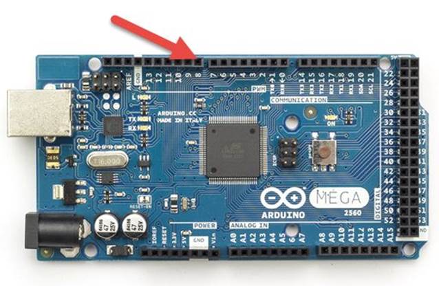
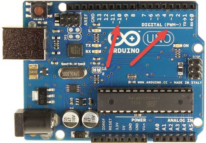
Please be careful if you want to work with Arduino PWM. If you have Arduino Mega, you will see PWM label so you obtain PWM pins easily but if you have Arduino Uno, it writes DIGITAL (PWM ~). It means your PWM pins can be found on DIGITAL pins which pin with ~, for instance, ~3,~5,~6,~9, ~10, ~11.
For Arduino Mega 2560, you can see PWM pins on picture below (see red arrow).
For Arduino Uno R3, you can see PWM pins as below.
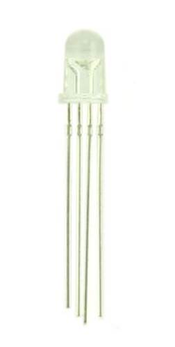
RGB LED has 4 pins that you can see it on Figure below.
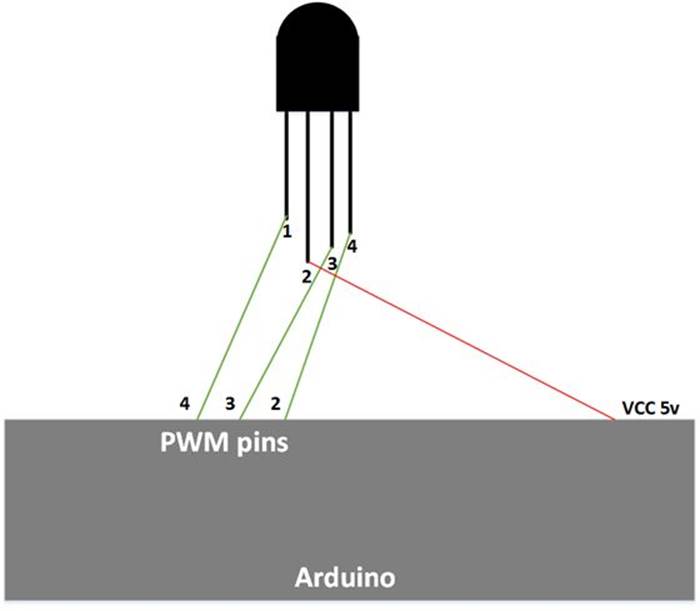
To understand these pins, you can see the following Figure.

Note:
· Pin 1: Red
· Pin 2: Common pin
· Pin 3: Green
· Pin 4: Blue
Now we can start to build a program and hardware implementation.
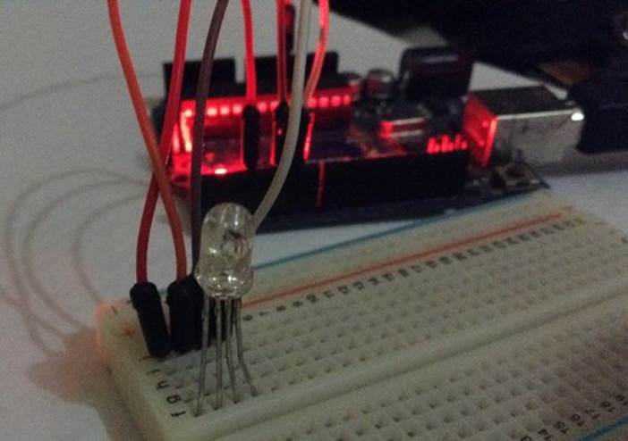
4.2.1 Wiring
Firstly we implement RGB LED hardware. The following is a hardware schema.
For our testing, we configure the following PWM pins.
Arduino Mega 2560:
· RGB LED pin 1 (red) is connected to Arduino PWM pin 3
· RGB LED pin 2 is connected to Arduino VCC 5V
· RGB LED pin 3 (green) is connected to Arduino PWM pin 5
· RGB LED pin 4 (blue) is connected to Arduino PWM pin 6
Arduino Uno R3:
· RGB LED pin 1 (red) is connected to Arduino PWM pin 3
· RGB LED pin 2 is connected to Arduino VCC 5V
· RGB LED pin 3 (green) is connected to Arduino PWM pin 5
· RGB LED pin 4 (blue) is connected to Arduino PWM pin 6
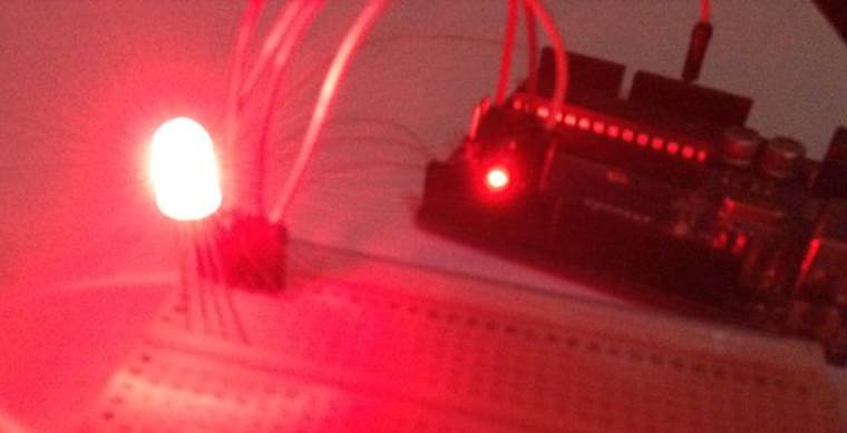
Here is a sample implementation with Arduino Uno R3.
4.2.2 Writing Program
To display a certain color, we must combine colors from red, green, blue. MATLAB provides API for PWM like Arduino API such as writePWMDutyCycle() with analog value from 0 to 1.
Let"s start to build a program. Firstly, open MATLAB. Then, write these scripts.
function [] = led_rgb()
board = arduino();
finishup = onCleanup(@() exitprogram(board));
configurePin(board,'D3','PWM');
configurePin(board,'D5','PWM');
configurePin(board,'D6','PWM');
disp('press Ctr-C to exit');
while1
disp('red');
write_rgb(board,0,1,1); % red
pause(1);
disp('green');
write_rgb(board,1,0,1); % green
pause(1);
disp('blue');
write_rgb(board,1,1,0); % blue
pause(1);
disp('yellow');
write_rgb(board,0,0,1); % yellow
pause(1);
disp('purple');
write_rgb(board,0.3,1,0.3); % purple
pause(1);
disp('aqua');
write_rgb(board,1,0,0); % aqua
pause(1);
end
end
% testing for Arduino Uno
functionwrite_rgb(board,r,g,b)
writePWMDutyCycle(board,'D3',r);
writePWMDutyCycle(board,'D5',g);
writePWMDutyCycle(board,'D6',b);
end
functionexitprogram(b)
clear b;
disp('program has exit');
end
Save this program as led_rgb.m.
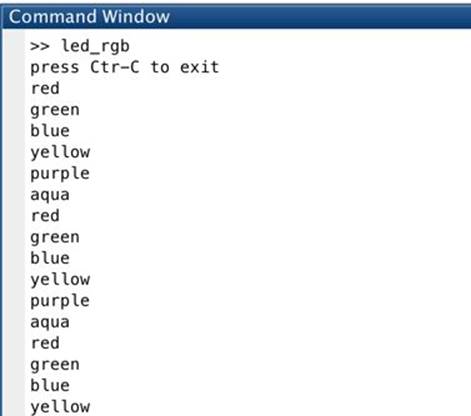
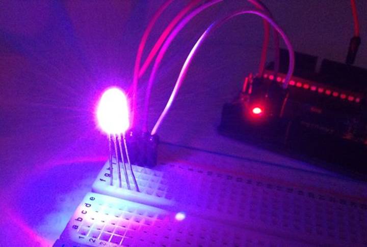
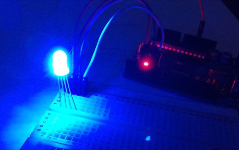
This program will generate six colors: red, green, blue, yellow, purple, and aqua.
4.2.3 Testing
Upload and run the program. You should see several color on RGB LED.
>> led_rgb
The following is a sample demo on Command Window on MATLAB.
The following is a sample demo on hardware.
4.3 Demo Analog Output Voltage: LED Brightness
In this demo, we try to control LED brightness by controlling voltage on LED. MATLAB for Arduino support provides writePWMVoltage() function to set voltage on PWM pins. We can set a voltage value from 0 to 5 for Arduino Uno/Mega and 0 - 3.3 for Arduino Due.
Let's build.
4.3.1 Wiring
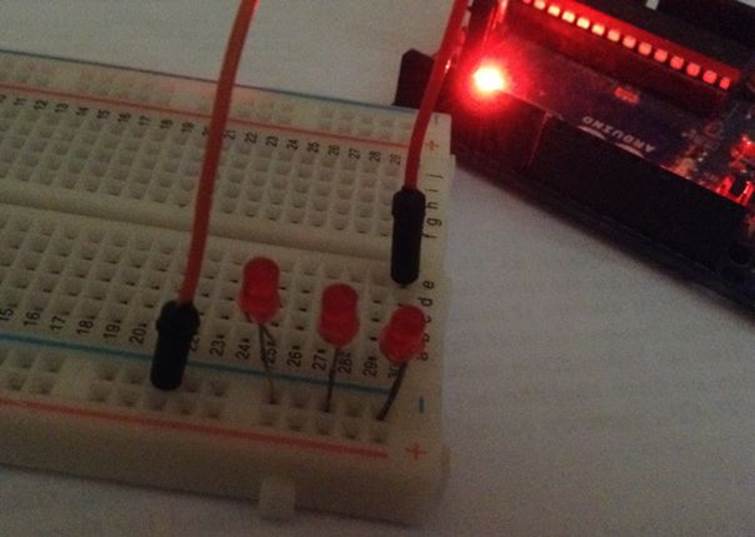
We connect a LED on PWM pin on digital pin 3. The following is my hardware wiring.
4.3.2 Writing a Program
Now you can open MATLAB and write these scripts.
function [] = led_brightness()
board = arduino();
finishup = onCleanup(@() exitprogram(board));
configurePin(board,'D3','PWM');
disp('press Ctr-C to exit');
while1
for k = 0:5
writePWMVoltage(board,'D3',k);
pause(1);
end
for k = 5:-1:0
writePWMVoltage(board,'D3',k);
pause(1);
end
end
end
functionexitprogram(b)
clear b;
disp('program has exit');
end
Save these scripts into a file, called led_brightness.m.
This program will set voltage value on PWM pin on digital pin 3 from 0 to 5 and then set a value from 5 to 0 too.
4.3.3 Testing
Make sure Arduino board already connected to your computer. You can run the program by typing this command.
>> led_brightness
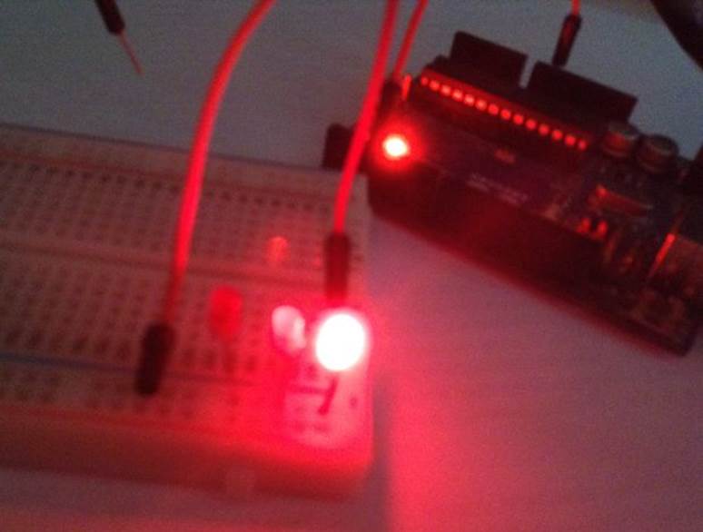
On hardware side, you should see LED brightness changing gradually.
4.4 Demo Analog Input: Working with Potentiometer
In this section, we learn how to read analog input on Arduino board. For illustration, I use Potentiometer as analog input source. Our scenario is to read analog value from Potentiometer. Then, display it on console.
Let's start!.
4.4.1 Wiring
To understand Potentiometer, you see its scheme in Figure below.
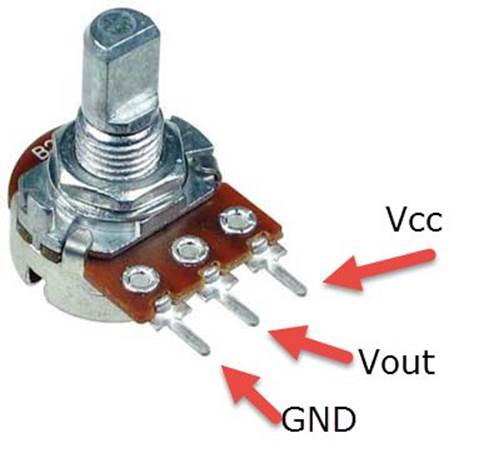
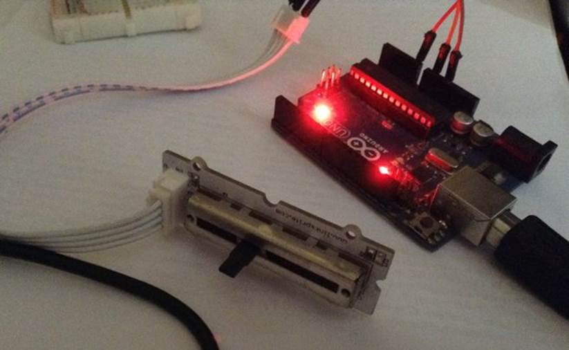
You can connect VCC to Arduino board on VCC +5V pin. Vout to Arduino board Analog input A0. In addition, GND to Arduino board GND. The following is hardware implementation. I use slide potentiometer.
4.4.2 Writing Program
Firstly, create a program via MATLAB. To read analog input, we can use readVoltage() function. Ok, Let's write these scripts.
function [] = potentiometer()
board = arduino();
finishup = onCleanup(@() exitprogram(board));
disp('press Ctr-C to exit');
while1
analog = readVoltage(board,'A0');
disp(['analog= ',num2str(analog)]);
pause(1);
end
end
functionexitprogram(b)
clear b;
disp('program has exit');
end
Save this code as potentiometer.m
4.4.3 Testing
To run the program, you can type this command.
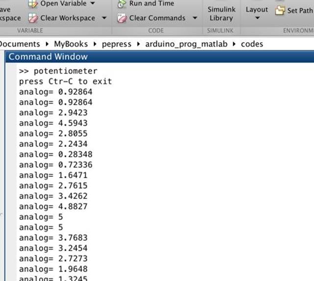
>> potentiometer
You should see analog value on Command Window.
All materials on the site are licensed Creative Commons Attribution-Sharealike 3.0 Unported CC BY-SA 3.0 & GNU Free Documentation License (GFDL)
If you are the copyright holder of any material contained on our site and intend to remove it, please contact our site administrator for approval.
© 2016-2026 All site design rights belong to S.Y.A.