Beginning Arduino Programming (Technology in Action) (2011)
Chapter 12. Beginning Electronics
Normally, in a book that is primarily focused on how to program the Arduino microcontroller, it makes sense not to spend too much time on basic electronics theory. That's not to say that knowledge of electronics isn't helpful to Arduino programmers, but an honors degree in electronics theory is not an absolute prerequisite to programming microcontrollers either. That is why this chapter finds its home here at the end of our book, as a brief introduction to beginning electronics; or if you already know how to solder and read schematics, it couldn't hurt to have a refresher. Hopefully, this chapter will help to explain in more depth some of the concepts we have discussed elsewhere in the book and maybe even inspire new and interesting projects.
With that in mind, this chapter will begin with a review of the theory of beginning electronics through the use of a range of electronic hardware. We will look at the basics of a circuit, including many of the common components, how to identify them, and how we can use them in our projects. We will also cover how to read schematics to build prototypes of circuits on breadboards. With all this out of the way, we will wrap up the chapter with a little primer on the basics of soldering to help, at the very least, with attaching pins to some of the breakout boards that we have used throughout the book.
What's needed for this chapter:
• Arduino Uno
• Assorted breakout boards or things to solder
• 0.1” male pin headers
• 5mm LED of any color
• 220-ohm ^-watt resistor or similar
• Momentary pushbutton or switch
• 9-volt battery
• Hookup wires
• Solderless breadboard
• Soldering iron
• Rosin core solder
• Sponge
Basic Electronics
When we discuss electronics, we are talking about generally small circuits using small amounts of electricity. These circuits handle electricity that is of lesser power by a great margin than that coming out of your wall outlet. Suffice to say, we won't be talking about residential electricity here. Instead we are concerned with small electrical signals used for sending information on the low end, to at the most enough electricity to spin a motor on the high end. To facilitate this conversation, we will start with a basic circuit to build from.
Circuits
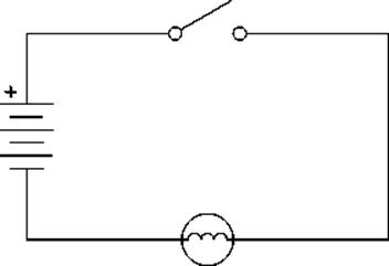
The image in Figure 12-1 shows a very simple little circuit.
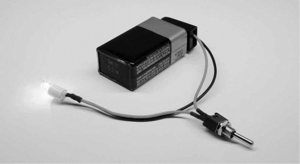
Figure 12-1. Basic circuit
This circuit has one job: to light up a lamp when the switch is closed. It has all of the prerequisites for a completed circuit that includes a power source, in this case a 9-volt battery, conductors in the form of insulated wires to carry the electricity, a load that resists the flow of current, here an incandescent lamp that produces light and a little heat in the process, and our circuit has a switch to interrupt the flow of electricity at our whim. A power source is needed to provide a source of electricity, whether this comes from the chemical reaction created inside of a battery or the power generated by a power plant down the road. Conductors, copper being an especially good one, send the electricity from the circuit's source to its load and back again, connecting each component to make a completed circuit. Components like our lamp create a resisting load when placed in the circuit that converts our electricity into something else, whether it's light, heat, movement, or so on. Without a sufficient load on the circuit, we would have a short circuit that would cause wires to melt, things to smoke, and other bad things to happen.
That is why it is important to remember two general rules about working with electronic circuits. The first is that electricity will follow the path of least resistance to ground. Accidently place a metal object or extraneous wire across any bare wires in our example circuit and rather than flowing through the lamp, the electrical current will jump through the metal thing instead creating a short circuit. This is also why insulators, materials that do not conduct electricity like plastic and rubber, are used to cover our wires.
The second thing to remember is that the available amount of energy in a circuit must all be used. This is where the smoke and bad things come in because we need to have a power source that matches the load in our circuit. If we accidentally hook the lamp up to 24 volts instead of providing it with a comfortable 9 volts, the lamp will get very bright and very hot for a very short amount of time. And then we won't have a complete circuit because the lamp will have moved on to the big place in the sky for unfortunate components.
Electricity
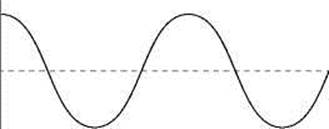
To make our circuit work we need to have electricity. Electrical current moves in a circle through a circuit from the point of highest potential to the lowest. For the purpose of discussion, in our circuit the current flows from the positive terminal of the battery, through the closed switch, into the lamp to produce light, and is completed when the used up current reaches the negative terminal of the battery. If we were to open the switch by turning it off, we would break the circuit and the electricity will not flow. This kind of flow is an example of Direct Current or DC, where the current flows though a circuit in one direction. DC is common in batteries and those black, little power transformers filling our kitchen drawers. The second way that electricity can flow through a circuit is by Alternating Current or AC. AC reverses polarity at regular intervals, 60 times per second in the US, and is the type of electrical current that comes into our homes and is available from our wall sockets. Figure 12-2 shows a representation of these two different currents.
0V
TIME —
ALTERNATING CURRENT (AC)
0V
TIME—֊
DIRECT CURRENT (DC)
Figure 12-2. Electrical currents
There are three characteristics about our electrical circuit that are dependent on one another. The first of these is current or the amount of electrical energy that flows through a certain point in our circuit and is measured in amperes or amps. The second characteristic is voltage or the difference in potential between two points in a circuit, sometimes simply referred to as the circuit's electrical energy and is measured in volts. The third characteristic is the resistance placed on our circuit by our load is measured in ohms. The relationship between current, voltage, and resistance has been expressed in Ohm’s Law, which can be summarized in the following equation:
Voltage = Current x Resistance
This equation could also be written as the following, depending on which characteristic you would like to solve for:
Current = Voltage + Resistance
or
Resistance = Voltage -Ւ Current
Admittedly, this may not be that important to you if all you are doing is hooking up the circuits found in this or other books verbatim, but it could come in handy sometime. Say for example that you buy an LED instead of a lamp to build our basic circuit. The LED itself has very little resistance and might only be rated for +3v at 25 milliamps. If we were to connect the LED straight to the 9v battery, we would have the closest thing to a short circuit and the poor LED wouldn't make it very long. Instead, we need to use a resistor in series with the LED to limit the current flowing through it. Using Ohm's Law, we could solve for this resistance using the following formula:
R = 9V ֊ .025A = 360 OHMS
By dividing 25 milliamps, or .025 amps, into 9 volts, we find that we need a resistor of about 360 ohms to use the entire available amount of energy. Since a 360-ohm resistor might be a little tricky to find, we can use a 330-ohm resistor instead because that's close enough, and close enough works for us. The LED and resistor in this example are two forms of components that are placed in our circuits. Let's look at others.
Common Components
While there are so many different electronic components, to discuss them all would fill a book larger than this one, so we are going to only look at a few of the very common components here. The idea is to get a sense of what these components look like and generally what kinds of things they do. That way, when you see them discussed or drawn up in a schematic, you'll have an idea of what you're looking at.
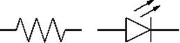
Resistors
A resistor limits, or resists, the flow of electricity. They are often useful in a circuit that would not ordinarily place much resistance on the total load, like our LED. In this way, the resistor uses up the current by producing a small amount of heat. Fixed resistors have two wires, have no polarity (so they can be placed in a circuit in any direction), and are rated in ohms, the measurement of resistance, and watts, an indication of the amount of heat the resistor can take. Fixed resistors are marked with either a series of colored bands or other printed markings that determine the resistor's value. Figure 12-3 shows many different kinds of resistors.
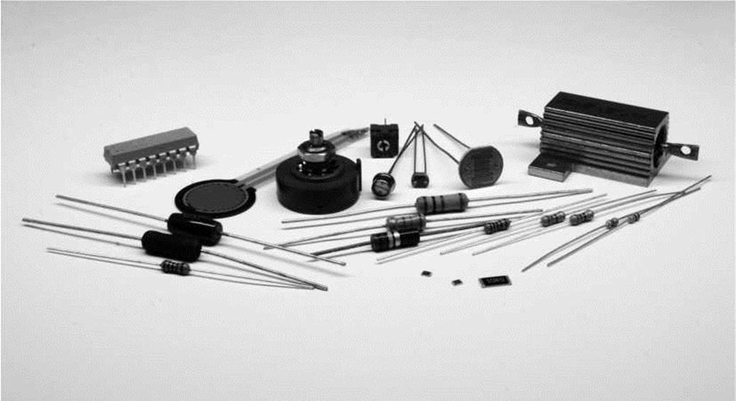
Figure 12-3. Resistors
In addition to resistors of the various types and sizes shown ranging from one-sixteenth of a watt to a massive 25-watt aluminum resistor, this image also shows several types of variable resistors. These resistors change their resistance depending on what kind of resistor they are. For example, a photoresistor or photocell will change its resistance depending on how light or dark it is, or how much or how little light hits the resistor. A thermistor changes resistance based on its temperature. A force sensitive resistor will respond to the amount of pressure or force applied to it. A special kind of resistor called a potentiometer will change resistance based on the position of a knob or slider.
We will use resistors for all manner of things, from limiting the current to other devices, reducing the voltage in a circuit, to measuring the change of variable resistors.
Capacitors
A capacitor will store an electrical charge when current is flowing into it only to release this charge when the current has been removed. Capacitors come in many different shapes and sizes, as shown in Figure 12-4, and are made from many different materials, but they all pretty much do the same thing. Their amount of capacitance is rated in a ridiculously large unit called a farad, although our capacitors will be a lot smaller than this, ranging from microfarads (pF) or a millionth of a farad, nanofarads (nF) a billionth of a farad, and picofarads (pF) a trillionth of a farad. These are small values indeed.
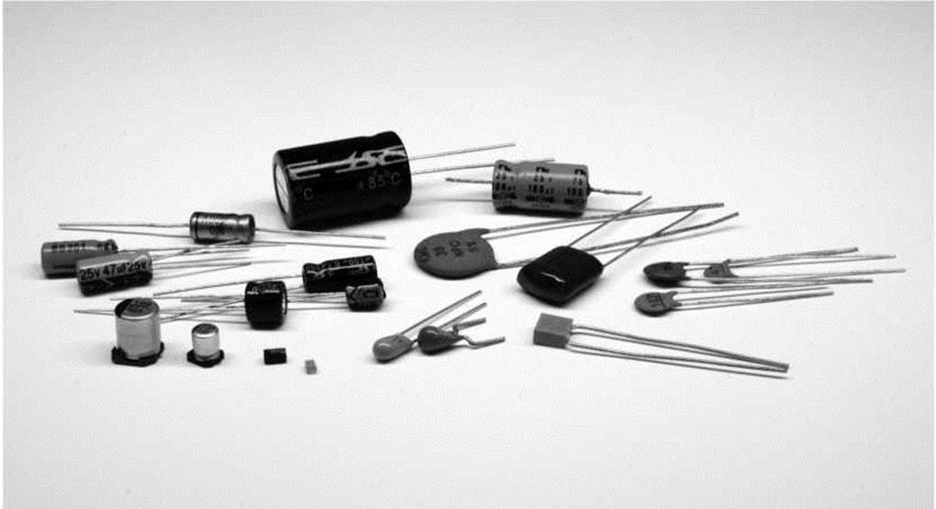
Figure 12-4. Capacitors
Inside a capacitor are two, parallel plates of conductive material separated by an insulating dialectic material. Common materials include an electrolytic oil, tantalum, ceramic, mica, and polyester. Some capacitors, like the electrolytic and tantalum capacitors, are polarized while others are not. Some circuits require one or the other, so pay attention to this as placing a polarized capacitor in a circuit the wrong way around might cause it to explode and damage other components.
We will often use capacitors to filter electronic signals, smoothing out any dips in the level of current caused by heavy or “noisy” loads. They are a necessary part of voltage regulation circuits and circuits that use motors to keep things running smoothly.
Diodes
Diodes are devices that will only allow the current to flow through a circuit in one direction. By necessity, diodes are polarized, meaning that they can only go into a circuit one way. The diode will only conduct electricity when the side called the anode (+) is more positive than the side called the cathode (-). The cathode in a standard diode is usually marked with a line. If current attempts to enter the diode the wrong way, it will be blocked and will not pass through. Figure 12-5 shows a selection of diodes.
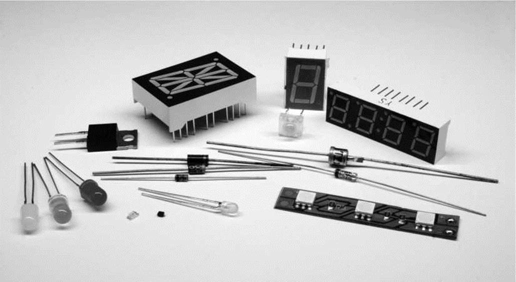
Figure 12-5. Diodes
There are generally two types of diodes that we will most often use. The first is a general purpose rectifier diode, such as the 1N4001. This is used for applications where we need to protect our circuit from reverse voltages that can be caused by inductive loads such as motors, solenoids, or relays.
Arguably the most common diode is the light-emitting diode that we have used many times throughout the book already. LEDs are fairly popular with the microcontroller crowd because they are so simple to connect and require small amounts of power to run. These diodes will emit light when electricity passes through them. The anode or positive (+) pin is usually the longer pin, while the cathode or negative (-) pin is the shorter one. LEDs come in many shapes, sizes, and colors, from 10mm to 3mm; miniature surface mount to large multi-watt LEDs; as well as seven-segment and alphanumeric displays for displaying numbers and letters.
Transistors
Transistors can be used just like an electrical switch. A small amount of current supplied to one pin of the transistor can switch a much greater load connected to the other pins. A bipolar transistor has three pins or wires that include the base, collector, and emitter. Figure 12-6 shows a few of the different packages available for transistors.
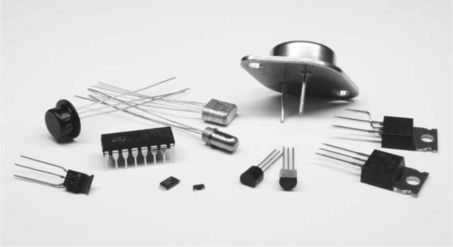
Figure 12-6. Transistors
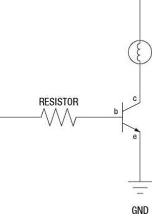
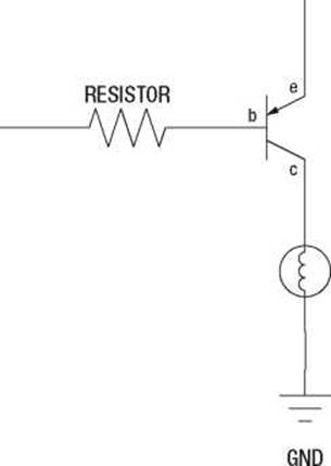
There are two types of transistors that we are mostly concerned with. The NPN transistor, such as the 2N3904, is capable of sinking current in a circuit, allowing for current to flow from the collector pin to the emitter pin whenever current is applied to the base pin. Occasionally, we will need to use a PNP transistor, like the 2N3906, which reverses the direction of the NPN, sourcing current rather than sinking it, allowing for current to flow from the emitter pin to the collector pin whenever current is applied to the base pin. The concepts of sourcing and sinking were explained more thoroughly in Chapter 5, but Figure 12-7 provides two example schematics for how this works with NPN and PNP bipolar transistors.
+VDC
SIGNAL
LAMP
2N3904
+VDC
SIGNAL
2N3906
LAMP
We will get to reading schematics shortly, but even so, hopefully, these two schematics will illustrate the differences of the NPN and PNP transistors. We use the NPN transistor, like in the schematic on the left, to switch a load on the low side or negative side of the load. The PNP, on the other hand, like in the schematic on the right, is used to switch the high side or positive side of the load.
Another kind of transistor is the Metal Oxide Field Effect Transistor or MOSFET. MOSFETs, such as the IRF540, are available in N-channel and P-channel varieties, similar to NPN and PNP transistors. Unlike transistors though, MOSFETs are capable of handling larger currents and switch faster than our run-of-the-mill transistors. They are best used for large motors, high-wattage LEDs, heaters, or similar applications.
Switches
Switches are the human-operable, mechanical version of transistors. Their job is to interrupt or allow current to flow through a circuit. They do this with metal contacts inside the switch that either close or open when the switch is activated. There are many different kinds of mechanical switches, including momentary pushbuttons, slide switches, lever switches, reed switches, tilt switches, toggle switches, and even relays are a kind of mechanical switch. Many of these are shown in Figure 12-8.
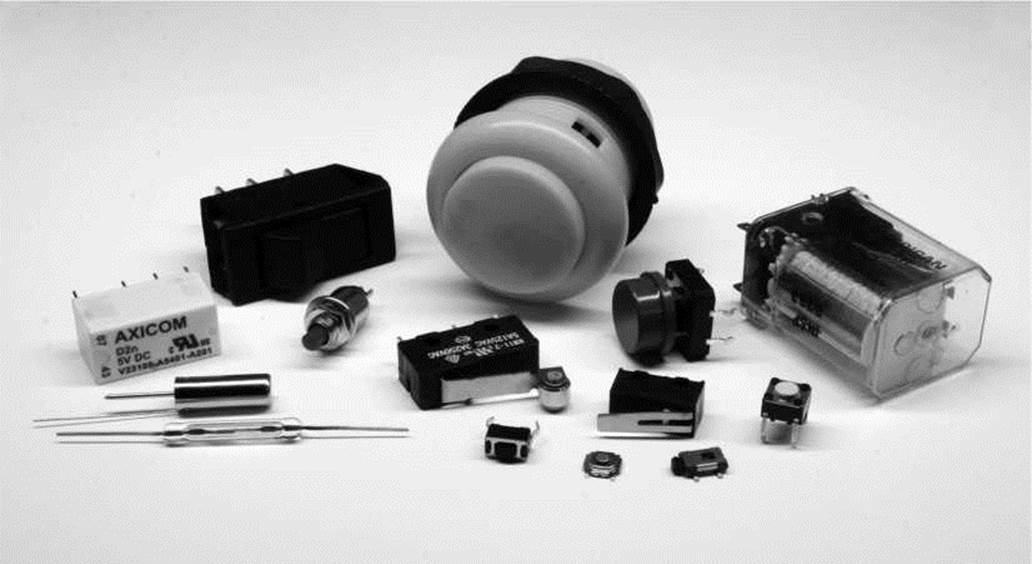
Figure 12-8. Switches
The contacts of a switch are either normally open, N.O., or normally closed, N.C. So for example, a circuit with a normally open momentary pushbutton with two contacts will be open until the button is pressed closing the circuit. When the button is released again, the circuit is once again open. A lever switch with three contacts might have one pin labeled N.O., another N.C., and a third C. for common. When a circuit is connected to the N.O. and C. contacts, the circuit will be normally open and closed when the switch is activated. On the other hand, if the circuit were connected to the N.C. and C. contacts, the circuit would remain closed until the switch is activated, when it would open the circuit.
In addition to momentary and lever switches, slide switches or toggle switches stay in whatever position they were last left in. Slide and toggle switches are just like your vanilla, household light switch. Tilt switches, like we used earlier in the book, have a rolling ball inside that close or open the contacts depending on the angle of the switch. Reed switches have a pair of thin metal contacts inside a glass container that will close when a magnet passes near. These are often seen in alarm systems to alert when a window or door has been opened.
Relays have also been included here with other mechanical switches. The relay is a switch that is activated by a magnetic coil. When the coil is given an electric current, it closes the nearby contacts. Where transistors are only good for switching DC voltages, some relays can switch much higher AC voltages, although these relays will often need a transistor to power the larger magnetic coil to activate the switch. Many relays will also have multiple N.O. and N.C. positions available to hook up many different things.
Motors
Motors are included here because they are another common mechanical component used in many of our projects. They will either create radial motion, what we might typically associate with a motor, as well as linear motion using solenoids or other devices. Figure 12-9 shows a few of the many different types of motors available.
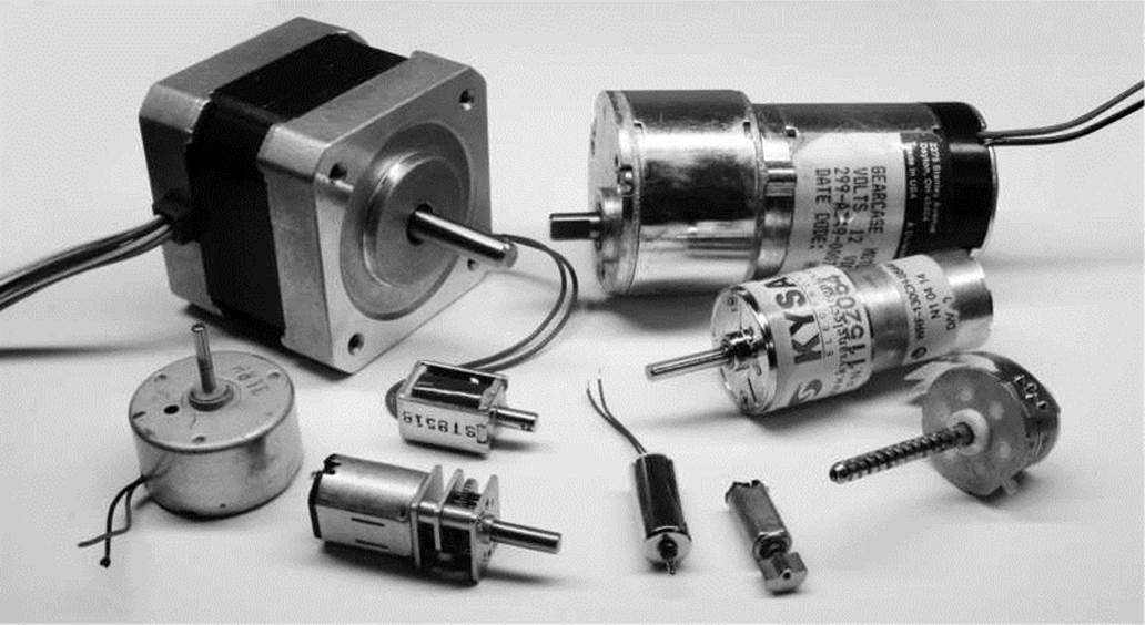
Figure 12-9. Motors
These are all DC-type motors. Motors that run on AC are as plentiful, but are also a bit more difficult to interface with microcontrollers. Radial DC motors are offered with or without built-in gearboxes.
Those motors with built-in gear boxes are called gearheads and generally run at much slower speeds, but increase the total available torque that the motor can provide. Solenoids are a type of motor that causes a shaft to contract or expand, creating linear movement when electricity is applied.
Different types of motors will have different types of characteristics. The ratings that we should be most concerned with are the motor's voltage and stall current. The rated voltage of a motor is for peak efficiency, although we can generally power a motor with a little more or less than it is rated for. The motor's stall current is the amount of amps the motor will pull when some force has caused the motor to stop moving. While the motor will generally run well below its stall current rating, our available power and switching mechanisms need to be rated for the greater stall current with a little room to spare to be on the safe side.
Radial motors are often also rated in revolutions per minute or RPM that tell us how fast the motor will spin. The speed of the motor is not as important for stepper or servo motors, which are more concerned with the positional accuracy, specified in degrees per step and total steps per revolution. Motors will also usually be rated for its pulling force or torque. This is measured by the amount of force the motor can apply at a given distance from the center of the motor's shaft. This rating is far from standard with measurements in oz/in, or ounces per inch; lb/ft, or pounds per foot; g/cm, or grams per centimeter; and even N/cm, for newtons per centimeter.
While we could continue to list category after category of components, we should probably stop here and talk about how we can use these components in our prototypes.
Reading Schematics
Let's revisit our basic circuit that we discussed earlier in this chapter from Figure 12-1, drawing it up in a type of diagram shown in Figure 12-10.
SWITCH
LAMP
Figure 12-10. Basic circuit schematic
+9 VDC
This drawing, an exact representation of the gadget in Figure 12-1, is a fairly standard wiring diagram called a schematic. We've been using them throughout this book, but you might want to know a little more about how they work. Schematics are a bit pictographic, like something out of the caves of Lascaux, but it shows us clearly how the circuit described earlier is connected. Once we know what the somewhat standardized symbols mean, in that a squiggle in a circle is a lamp, a bunch of long and short parallel lines is a battery, and a switch kind of looks like a broken line, then we can follow along with the drawing, connecting one component to another just as the lines in the schematic connect components together.
To make things easier in this book, all of our schematics have had an accompanying illustration to provide a little better sense of the completed prototyped circuit, but once you get a feeling for what all those symbols mean then it's not really all that bad. Being able to read a schematic also makes it a lot easier to wire things up. Some of the more common schematic symbols are shown in Figure 12-11.
+5 VDC
-ЛЛ/Ѵ-
g
d
s
LAMP N-CH MOSFET
RESISTOR VAR RESISTOR MOTOR
DC SOURCE GROUND
+
b
T
AC SOURCE BATTERY PHOTO RESISTOR LED POLAR CAPACITOR SWITCH NPN TRANSISTOR
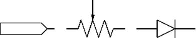
Figure 12-11. Common schematic symbols
b
SPEAKER
SIGNAL POTENTIOMETER DIODE CAPACITOR RELAY PNP TRANSISTOR
While these symbols are somewhat abstract, they are also loosely based on reality. Some resistors are made by winding a long length of wire very tightly in a small package, capacitors have two plates that are sometimes separated by air, and diodes let electricity pass in one direction but block it in the other. By reading these symbols, we can use these schematics to build prototype circuits on our breadboards.
Prototyping
Prototyping is a way to quickly realize a circuit and to see if it will work or not. By prototyping a thing, we can build something without spending a lot of time and money wiring everything up from scratch. This is great for focusing our efforts and our ideas rather than getting lost in soldering wires from one component to another. One of the best things that we can use to help make prototyping even easier is a breadboard.
Breadboards
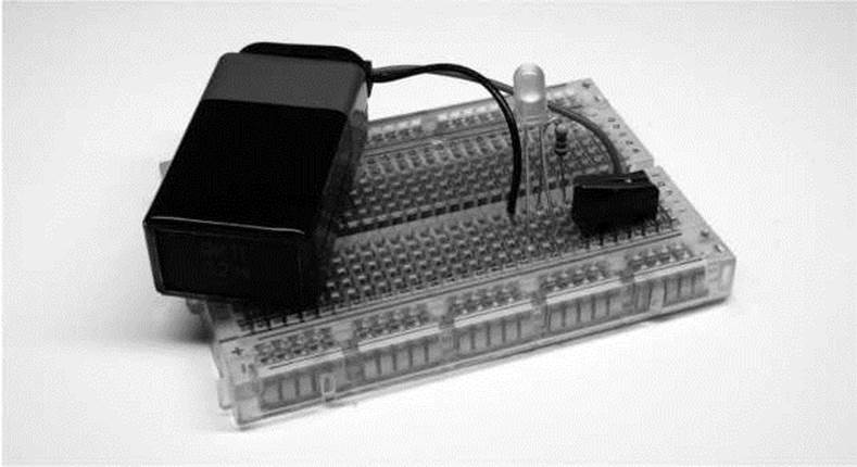
Historically, amateur radio builders would put together circuits using wires and nails quite literally on cutting boards for bread. Today, we use the solderless breadboard, shown in Figure 12-12, to quickly prototype a circuit.
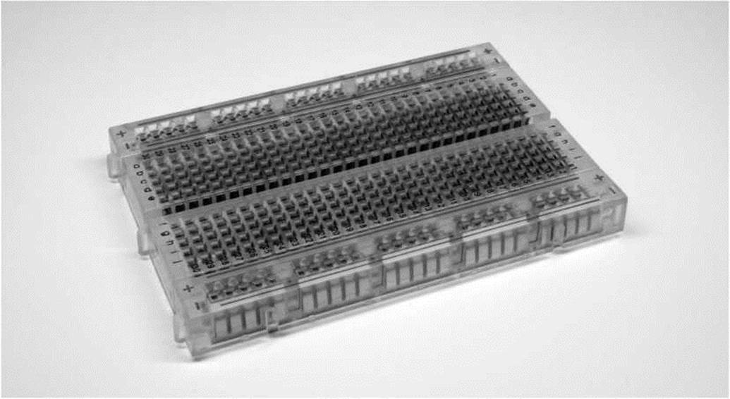
Figure 12-12. A solderless breadboard
This image shows one of the currently popular breadboards with a clear plastic casing. On the outside there are about 244 little square holes in the face of the breadboard. Inside, you can see rows of metal clips. When a component's metal leg is placed into the breadboard, these internal clips connect that pin to others in that row. It can be a little tricky to understand exactly how these connections are made, so Figure 12-13 illustrates the hole pattern on the face of the board as well as the internal connection inside of it.
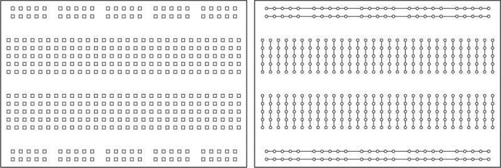
BREADBOARD HOLE PATTERN BREADBOARD INTERNAL CONNECTIONS
In this type of breadboard, two, long, power busses on both sides of the breadboard are useful for providing a + and - power supply rail that runs along the length of the board. On either side of a channel that runs down the center of the board are two rows of holes where each row of five holes are connected to each other. This center divider keeps these two sides separate and provides a place for integrated circuits that typically have two rows of pins to be plugged into the board and still be connected to other devices without inadvertently connecting the two sides of the IC together. Keep in mind that any pin inserted into one of these adjacent five positions will be connected to one another inside of the breadboard.
Now, to get a better sense for how can we use the breadboard to prototype a basic circuit, let's try one out. Figure 12-14 takes our basic lamp circuit and changes out a few of the components.
SWITCH
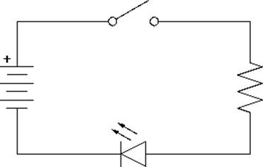
RESISTOR
Figure 12-14. Basic LED circuit schematic
LED
In this circuit, we have replaced the incandescent lamp with a light-emitting diode and the necessary current limiting resistor, but otherwise the circuit will work just the same as before. Now let's look at Figure 12-15 to see what it looks like on the breadboard.
It’s important to notice here that the circuit in the breadboard does not necessarily look like the schematic. That’s because schematics are not meant to be a geographical map of what the circuit looks like but rather they simply show the connections that need to be made. Connecting one pin of the LED and one pin of the resistor into any of the five holes that share a connection will connect the LED to the resistor, completing that part of the circuit. Starting at the top left-hand side of the schematic, we see that the positive side of the battery connects to one side of the switch, the other side of the switch connects to the resistor, the second leg of the resistor connects to the positive or anode pin of the LED, and the negative pin or cathode of the LED connects to the negative terminal of the battery. We could place the components in this circuit in a nearly infinite number of ways, and as long as we made the same connections, then the circuit would work fine each time.
In our example, we connect the pins of each component right into the breadboard itself. If we had a more difficult circuit to build, we would need to use hookup wires to connect one point to another.
These wires can either be solid, insulated wire cut to length, we find that 22-gauge works best, or male-to-male, pre-terminated jumper wires. Keep in mind though that when building a circuit on a breadboard, or changing some of the components or wiring, it’s a good idea to disconnect any power source from the board, as crossing wires while the board is powered up could damage your components.
While the breadboard provides a quick and relatively painless way to prototype a circuit sometimes soldering two wires together, or parts like pin headers to breakout boards, is just unavoidable. So let’s look at what soldering is and how we can make permanent connections with reasonable success.
Soldering
We love our solderless breadboards for making our lives that much easier, but occasionally there is no escaping the need to solder. Maybe the pins on a switch don’t fit in the breadboard so we need to solder wires to it. Some of the breakout boards that we have been using do not already have pins attached when we buy them, so we need to solder pin headers to them to plug them into our breadboard. Figure 12-16 shows a couple of different breakout boards that will need a little soldering.
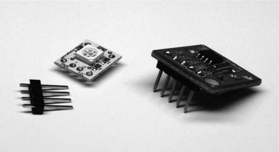
In this image are the BlinkM MinM smart LED and the DS1307 RTC breakout board from SparkFun Electronics. Unfortunately, neither of these devices comes ready to plug right into the breadboard. In the case of the BlinkM MinM, it includes the four-pin male pin header shown in the image, while the SparkFun device requires a separate purchase of the pin headers needed. Pin headers are kind of like the glue of electronics prototyping, so having a few extra on hand is always a good idea. We will make the assumption here that to complete some of the projects discussed earlier, you might want to know how to go about soldering these pins to these breakout boards.
To get started soldering you'll need to pick up a few things. The first thing, of course, is a soldering iron. On the low end, a $10–$20 pen-style soldering iron in the 30-watt ballpark is just fine for learning how to solder. A soldering stand and a sponge to clean the soldering iron tip are also good ideas. We like to use our Weller WES-51 adjustable soldering station, but other higher-end stations that run about $100 are also a good choice if you find that you'll be doing quite a bit of soldering. You will also need some solder. As long as you avoid the solder for copper pipes that you might find at the hardware store, you will probably be fine. We find .03” diameter 60/40 tin/lead rosin core solder works great for general, personal-use soldering. Other sizes and types of solders, including those that are lead-free, are also available and will work fine. It can also be tricky to hold four different things—the iron, solder, and two parts—while soldering, so some form of clamp or helper is also a good idea to have on hand.
A quick note here about safety. We are indeed recommending lead-based solder for personal use because of its ease of use and it is generally nicer to our irons. The fumes that come from soldering are mostly the rosin inside the solder burning off, but you do not necessarily want to make a habit of breathing it. Lead-free solder is not only harder on the iron, but it also uses far more toxic rosin, so you will want to seriously ventilate when using this type of solder, if you choose to use it. Either way, you should always wash your hands after handling any kind of solder.
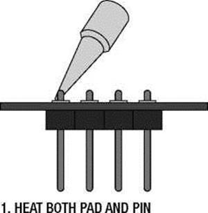
Okay, before we start soldering, we need to get the iron good and hot. We also want a nice, clean, and shiny tip at the end of our iron. We can get this by applying a little bit of solder to the tip of our iron and then wipe the tip across a damp sponge. This is a process called tinning. It is also a good idea to clean the tip before and after each use. A clean tip will make the heat transfer better and the solder flow more smoothly. With a properly tinned tip, it's now time to solder. Figure 12-17 provides the illustrated and abbreviated version of this process.
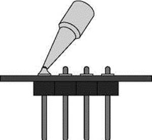
3. REMOVE SOLDER
Figure 12-17. Soldering
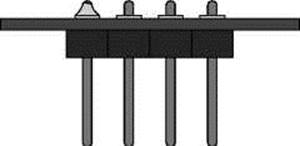
4. REMOVE IRON
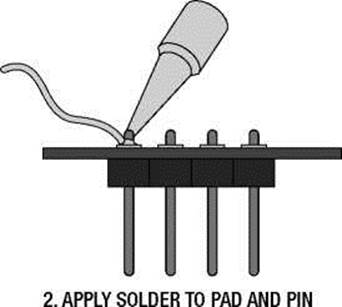
Our example assumes that you want to solder pin headers to a printed circuit board, or PCB, although this process is fundamentally the same as soldering two wires together. Generally, we want to equally heat both parts with the tip of the iron and apply the solder to the two heated parts to be soldered and not directly to the soldering iron tip. We do this by putting the two parts together so that the metal bits are in contact, and then place the tip of the iron so that it touches both of these parts. In reality, we are using both the very tip and the side of the tip to make a good enough contact with both parts. In our example, we are soldering the short side of the pin header to the copper pad surrounding the hole that the pin was fed through on the circuit board.
When the parts are sufficiently heated, solder can be applied to the parts and it should flow quickly and smoothly when there is enough heat and everything is clean. Sometimes we will touch the solder to the tip of the iron to start the flow of molten solder, but we want to keep the solder on the parts to be soldered and not the iron. Remove the solder when a nice little mountain of solder has formed, but leave the iron heating things for another second or so. Once the solder has had a chance to flow over the whole pad, we can then remove the iron allowing the joint to cool naturally.
When the joint has been soldered correctly, you should have a clean and shiny little mound of solder that completely fills the copper pad and fully encompasses the pin. Sometimes when we don't add enough solder to the joint, we will end up with a pin that is only partially attached. This might work initially, but can create problems later when you least expect it. The simple fix is to simply heat up the joint and add more solder. However, if we add too much solder, we will end up with an enormous blob that might come into contact with other nearby pins or pads on the board. To fix this, we just need to heat up the solder again and shake or tap the board to remove the extra solder. Other times, instead of a shiny little mountain, we might end up with a solder joint that is dirty and dull looking. This is what's called a cold solder joint and happens when the tip is either not clean or not hot enough for the job.
Make sure that your iron has had time to fully heat up, check that the tip is clean, and if you have an adjustable iron, set the iron to a higher temperature.
Like learning to ride a bicycle, soldering is a whole lot of fun, but it takes time and practice to get it right. The best way to learn is to pick up some electronic kits from Adafruit, SparkFun, or the Maker SHED. Electronic kits like the Minty Boost, Simon Soldering Kit, and the Atari Punk Console are all great places to continue practicing your soldering skills.
Summary
See, that was a lot of fun. In this chapter we looked at a very fundamental—maybe overly abbreviated— review of electronics theory and we got a sense for some of the more common types of components and what we might use them for. We also revisited how to read schematics and build prototypes from them using the nifty little gadget called a solderless breadboard. We even tackled how to solder pin headers to breakout boards to make some of the devices we've used more breadboard-friendly.
With that, we have reached the end of our book. By now, you should have a solid foundation of programming Arduino C; you have a working knowledge of how things like control structures, variables, functions, memory, arrays, and libraries are all handled; hopefully, you've been inspired to try out some new project ideas or get involved in the community; and you even have a basic grasp of working with electronic prototypes to make your next projects even easier.
I hope you've enjoyed reading this book as much as I've had writing it and found its content challenging but interesting, useful, and even a little fun too. I look forward to hearing from you and seeing the things that you will make.
All materials on the site are licensed Creative Commons Attribution-Sharealike 3.0 Unported CC BY-SA 3.0 & GNU Free Documentation License (GFDL)
If you are the copyright holder of any material contained on our site and intend to remove it, please contact our site administrator for approval.
© 2016-2026 All site design rights belong to S.Y.A.