Programming Arduino Getting Started with Sketches (2012)
7
The Standard Arduino Library
This library is where all the goodies live. You can only get so far with the core C language; what you really need is a big collection of functions that you can use in your sketches.
You have already met a fair few of these, such as pinMode, digitalWrite, and analogWrite. But actually, there are many more. There are functions that you can use for doing math, making random numbers, manipulating bits, detecting pulses on an input pin, and using something called interrupts.
The Arduino language is based on an earlier library called Wiring and it complements another library called Processing. The Processing library is very similar to Wiring, but it is based on the Java language rather than C and is used on your computer to link to Android over USB. In fact, the Arduino application that you run on your computer is based on Processing. If you find yourself wanting to write some fancy interface on your computer to talk to an Arduino, then take a look at Processing (www.processing.org).
Random Numbers
Despite the experience of anyone using a PC, computers are in actual fact very predictable. Occasionally it is useful to be able to deliberately make your Arduino unpredictable. For example, you might want to make a robot take a “random” path around a room, heading for a random amount of time in one direction, turning a random number of degrees, and then setting off again. Or, you might be contemplating making an Arduino-based die that gives you a random number between one and six.
The Arduino standard library provides you with a feature to do just this. It is the function called random. random returns an int and it can take either one argument or two. If it just takes one argument, then it will return a random number between zero and the argument minus one.
The two argument version produces a random number between the first argument (inclusive) and the second argument minus one. Thus random(1, 10) produces a random number between one and nine.
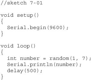
Sketch 7-01 pumps out numbers between one and six to the Serial Monitor.
If you upload this sketch to your Arduino and open the Serial Monitor, you will see something like Figure 7-1.
If you run this a few times you will probably be surprised to see that, every time you run the sketch, you get the same series of ‘random’ numbers.
The output is not really random; the numbers are called pseudo-random numbers because they have a random distribution. That is, if you ran this sketch and collected a million numbers, you would get pretty much the same number of ones, twos, threes, and so on. The numbers are not random in the sense of being unpredictable. In fact, it is so against the workings of a microcontroller to be random that it just plain can’t do it without some intervention from the real world.
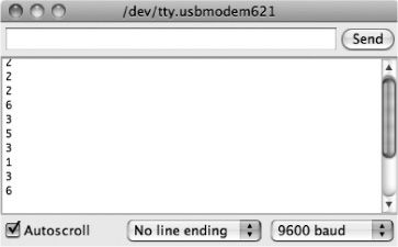
Figure 7-1 Random numbers
You can provide this intervention to make your sequence of numbers less predictable by seeding the random number generator. This basically just gives it a starting point for the sequence. But, if you think about it, you cannot just use random to seed the random number generator. A commonly used trick is to use the fact that (as discussed in the previous chapter) an analog input will float. So you can use the value read from an analog input to seed the random number generator.
The function that does this is called randomSeed. Sketch 7-02 shows how you can add a bit more randomness to your random number generator.
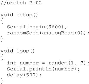
Try pressing the Reset button a few times. You should now see that your random sequence is different every time.
This type of random number generation could not be used for any kind of lottery. For much better random number generation, you would need hardware random number generation, which is sometimes based on random events, such as cosmic ray events.
Math Functions
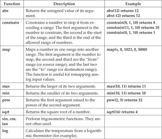
On rare occasions, you will need to do a lot of math on an Arduino, over and above the odd bit of arithmetic. But, should you need to, there is a big library of math functions available to you. The most useful of these functions are summarized in the following table:
Bit Manipulation
A bit is a single digit of binary information, that is, either 0 or 1. The word bit is a contraction of binary digit. Most of the time, you use int variables that actually comprise 16 bits This is a bit wasteful if you only need to store a simple true/false value (1 or 0). Actually, unless you are running short of memory, being wasteful is less of a problem than creating difficult-to-understand code, but sometimes it is useful to be able to pack your data tightly.
Each bit in the int can be thought of as having a decimal value, and you can find the decimal value of the int by adding up the values of all the bits that are a 1. So in Figure 7-2, the decimal value of the int would be 38. Actually, it gets more complicated to deal with negative numbers, but that only happens when the leftmost bit becomes a 1.
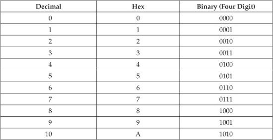
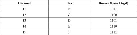
When you are thinking about individual bits, decimal values do not really work very well. It is very difficult to visualize which bits are set in a decimal number such as 123. For that reason, programmers often use something called hexadecimal, or, more commonly, just hex. Hex is number base 16. So instead of having digits 0 to 9, you have six extra digits, A to F. This means that each hex digit represents four bits. The following table shows the relationship among decimal, hex, and binary with the numbers 0 to 15:
So, in hex, any int can be represented as a four-digit hex number. Thus, the binary number 10001100 would in hex be 8C. The C language has a special syntax for using hex numbers. You can assign a hex value to an int as follows:
![]()
The Arduino standard library provides some functions that let you manipulate the 16 bits within an int individually. The function bitRead returns the value of a particular bit in an int; so, for the following example would assign the value 0 to the variable called bit:
![]()
In the second argument, the bit position starts at 0 and goes up to 15. It starts with the least significant bit. So the rightmost bit is bit 0, the next bit to the left is bit 1, and so on.
As you would expect, the counterpart to bitRead is bitWrite, which takes three arguments. The first is the number to manipulate, the second is the bit position, and the third is the bit value. The following example changes the value of the int from 2 to 3 (in decimal or hex):
![]()
![]()
Figure 7-2 An int
Advanced I/O
There are some useful little functions that you can use to make your life easier when performing various input/output tasks.
Generating Tones
The tone function allows you to generate a square-wave signal (see Figure 7-3) on one of the digital output pins. The most common reason to do this is to generate an audible tone using a loudspeaker or buzzer.
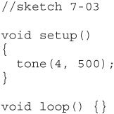
The function takes either two or three arguments. The first argument is always the pin number on which the tone is to be generated, the second argument is the frequency of the tone in hertz (Hz), and the optional final argument is the duration of the tone. If no duration is specified, then the tone will continue playing indefinitely, as is the case in sketch 7-03. This is why we have put the tone function call in setup rather than in the loop function.
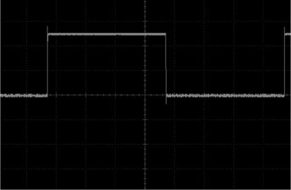
Figure 7-3 A square-wave signal
To stop a tone that is playing, you use the function noTone. This function has just one argument, which is the pin on which the tone is playing.
Feeding Shift Registers
Sometimes the Arduino Uno just doesn’t have enough pins. When driving a large number of LEDs, for example, a common technique is to use a shift register chip. This chip reads data one bit at a time, and then when it has enough, it latches all those bits onto a set of outputs (one per bit).
To help you use this technique, there is a handy function called shift-Out. This function takes four arguments:
• The number of the pin on which the bit to be sent will appear.
• The number of the pin to be used as a clock pin. This toggles every time a bit is sent.
• A flag to determine whether the bits will be sent starting with the least significant bit or the most significant. This should be one of the constants MSBFIRST or LSBFIRST.
• The byte of data to be sent.
Interrupts
One of the things that tend to frustrate programmers used to “programming in the large” is that the Arduino can do only one thing at a time. If you like to have lots of threads of execution all running at the same time in your programs, then you are out of luck. Although a few people have developed projects that can execute multiple threads in this way, generally this capability is unnecessary for the type of uses that an Arduino is normally put to. The closest an Arduino gets to such execution is the use of interrupts.
Two of the pins on the Arduino (D2 and D3) can have interrupts attached to them. That is, these pins act as inputs that, if the pins receive a signal in a specified way, the Arduino’s processor will suspend whatever it was doing and run a function attached to that interrupt.
Sketch 7-04 blinks an LED, but then changes the blink period when an interrupt is received. You can simulate an interrupt by connecting your wire between pin D2 and GND and using the internal pull-up resistor to keep the interrupt high most of the time.
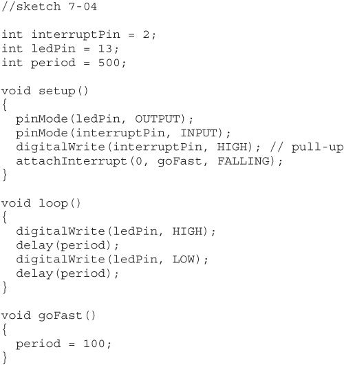
The following is the key line in the setup function of this sketch:
![]()
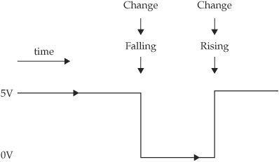
Figure 7-4 Types of interrupt signals
The first argument specifies which of the two interrupts you want to use. Rather confusingly, a 0 here means you are using pin 2, while a 1 means you are using pin 3.
The next argument is the name of the function that is to be called when there is an interrupt, and the final argument is a constant that will be one of CHANGE, RISING, or FALLING. Figure 7-4 summarizes these options.
If the interrupt mode is CHANGE, then either a RISING from 0 to 1 or a FALLING from 1 to 0 will both trigger an interrupt.
You can disable interrupts using the function noInterrupts. This stops all interrupts from both interrupt channels. You can resume using interrupts again by calling the function interrupts.
Conclusion
In this chapter, you have looked at some of the handy features that the Arduino standard library provides. These features will save you some programming effort, and if there is one thing that a good programmer likes, it is being able to use high-quality work done by other people.
In the next chapter, we will extend what we learned about data structures in Chapter 5 and look at how you go about remembering data on the Arduino after the power goes off.
All materials on the site are licensed Creative Commons Attribution-Sharealike 3.0 Unported CC BY-SA 3.0 & GNU Free Documentation License (GFDL)
If you are the copyright holder of any material contained on our site and intend to remove it, please contact our site administrator for approval.
© 2016-2026 All site design rights belong to S.Y.A.