Programming Arduino Getting Started with Sketches (2012)
9
LCD Displays
In this chapter, you look at how to write software to control LCD displays. Figure 9-1 shows the kind of LCD display used.
This is a book about software, not hardware, but in this chapter, we will have to explain a little about how the electronics of these displays work so that you understand how to drive them.
The LCD module that we use is a prebuilt Arduino shield that can just be plugged on top of an Arduino board. In addition to its display, it also has some buttons. There are a number of different shields, but nearly all of them use the same LCD controller chip (the HD44780), so look for a shield that uses this controller chip.
I used the DFRobot LCD Keypad Shield for Arduino. This module supplied by DFRobot (www.robotshop.com) is inexpensive and provides an LCD display that is 16 characters by 2 rows and also has six pushbuttons.
The shield comes assembled, so no soldering is required; you just plug it on top of your Arduino board (see Figure 9-2).
The LCD shield uses seven of the Arduino pins to control the LCD display and one analog pin for the buttons. So we cannot use these Arduino pins for any other purpose.
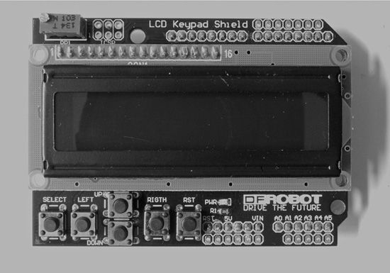
Figure 9-1 An Alphanumeric LCD shield
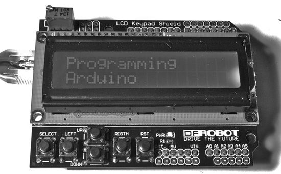
Figure 9-2 LCD shield attached to an Arduino board
A USB Message Board
For a simple example of a simple use of the display, we are going to make a USB message board. This will display messages sent from the Serial Monitor.
The Arduino IDE comes with an LCD library. This greatly simplifies the process of using an LCD display. The library gives you useful functions that you can call:
• clear clears the display of any text.
• setCursor sets the position in row and column where the next thing that you print will appear.
• print writes a string at that position.
This example is listed in sketch 9-01:
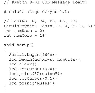
As with all Arduino libraries, you have to start by including the library to make the compiler aware of it.
The next line defines which Arduino pins are used by the shield and for what purpose. If you are using a different shield, then you may well find that the pin allocations are different, so check in the documentation for the shield.
In this case, the six pins used to control the display are D4, D5, D6, D7, D8, and D9. The purpose of each of these pins is described in Table 9-1.
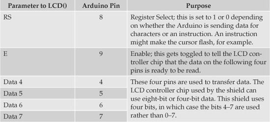
Table 9-1 LCD shield pin assignments
The setup function is straightforward. You start serial communications so that the Serial Monitor can send commands and initialize the LCD library with the dimensions of the display being used. You also display the message “Arduino Rules” on two lines by setting the cursor to top-left, printing “Arduino,” then moving the cursor to the start of the second row and printing “Rules.”
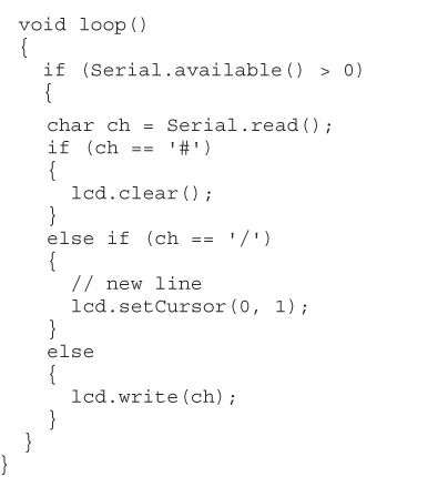
Most of the action takes place in the loop function, which checks for any incoming characters from the Serial Monitor. The sketch deals with characters one at a time.
Apart from ordinary characters that the sketch will simply display, there are also a couple of special characters. If the character is a #, then the sketch clears the whole display, and if the character is a /, the sketch moves to the second line. Otherwise, the sketch simply displays the character at the current cursor position using write. The function write is like print, but it prints only a single character rather than a string of characters.
Using the Display
Try out sketch 9-01 by uploading it to the board and then attaching the shield. Note that you should always unplug the Arduino board so that it is off before you plug in a shield.
Open up the Serial Monitor and try typing in the text shown in Figure 9-3.
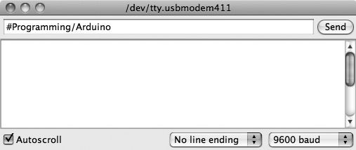
Figure 9-3 Sending commands to the display
Other LCD Library Functions
In addition to the functions that you have used in this example, there are a number of other functions that you can use:
• home is the same as setCursor(0,0): it moves the cursor to top-left.
• cursor displays a cursor.
• noCursor specifies not to display a cursor.
• blink makes the cursor blink.
• noBlink stops the cursor from blinking.
• noDisplay turns off the display without removing the content.
• display turns the display back on after noDisplay.
• scrollDisplayLeft moves all the text on the display one character position to the left.
• scrollDisplayRight moves all the text on the display one character position to the right.
• autoscroll activates a mode in which, as new characters are added at the cursor, the existing text is pushed in the direction determined by the functions leftToRight and rightToLeft.
• noAutoscroll turns autoscroll mode off.
Conclusion
You can see that programming shields is not hard, particularly when there is a library that can do a lot of the work.
In the next chapter, you will use an Ethernet shield that will allow you to connect the Arduino to the Internet.
All materials on the site are licensed Creative Commons Attribution-Sharealike 3.0 Unported CC BY-SA 3.0 & GNU Free Documentation License (GFDL)
If you are the copyright holder of any material contained on our site and intend to remove it, please contact our site administrator for approval.
© 2016-2026 All site design rights belong to S.Y.A.