Object-Oriented Analysis and Design for Information Systems: Modeling with UML, OCL, and IFML (2014)
CHAPTER 1
Introduction
The main goal of this book is to present a set of good practices that allows software developers to comprehend and use object-oriented principles in an effective and efficient way. This chapter presents the motivation for this book and a quick introduction to UML (Unified Modeling Language) and UP (Unified Process). The goal of this book is not to be another reference manual to such technologies, but to help people who are working with them to accomplish their jobs better.
Keywords
UML; Unified Process; object-oriented analysis; object-oriented design; object-oriented development; design patterns
Key Topics in this Chapter
• Object-Oriented Systems Development
• Unified Modeling Language (UML)
• Unified Process (UP)
1.1 This book
There is a vast literature that aims at syntactically presenting UML1 diagrams, such as for instance, Miles and Hamilton (2006). There are also a significant number of books about development processes and management activities, such as Satzinger, Jackson and Burd (2011). However, there are relatively few books that go really deep into the presentation of best practices that allow the effective application of object-oriented techniques in software development in the real world. This means that despite the vast literature in this area, many questions faced by developers are still left unanswered.
This book presents more details on many object-oriented concepts and activities, especially those presented by Larman (2004), which is based on the Unified Process, commonly known as UP (Jacobson, Booch, & Rumbaugh, 1999; Scott, 2001).
The reason this book is based on Larman’s concepts is because he presents a concise and efficient approach to systems analysis and design using an object-oriented paradigm. In his approach, each artifact (document or diagram) has a very clear and practical reason to exist and the connections between artifacts are very precise.
In our approach, agile principles adopted by Extreme Programming (XP) (Beck & Andres, 2004) are largely accepted. However, we propose that programming must be undertaken first using a modeling language before directly programming code. The use of UML diagrams as high-level programming tools instead of just documentation tools is recommended. With that approach, the artifacts used should contribute directly to the understanding of the problem (analysis) or to the design of a solution. In order to improve the process of designing a solution, we consider model transformation and automatic code generation fundamental.
Furthermore, in contrast to Larman’s work, this book presents some original concepts and other details on topics as follows:
• Objective criteria to identify use cases and decide when to subdivide them or not.
• A technique to expand use cases that reduces the disparity among descriptions created by different analysts (the concept of mandatory and complementary steps allows one to decide exactly how many steps a use case must have).
• System sequence diagrams built with actor, interface, and control (instead of actor and system only) to help realize a clear difference between system events and system operations.
• An original approach for writing system commands and queries contracts with the use of the Object Constraint Language, OCL (Object Management Group, 2010) that allows for automatic generation of running code, and not only postcondition checking, as current tools do.
• An adaptation of Fowler’s (2003) analysis patterns to UML, and restructuring some of those patterns to simplify their identification and application in practice.
• A systematic technique to generate dynamic object models from OCL contracts, which follows good design patterns, and reduces significantly the amount of code necessary for running an application, avoiding, for example, redundant verifications.
• An interface tier design presented with the use of IFML (Interaction Flow Modeling Language), a brand new OMG standard for interface modeling.
The aforementioned features are useful for producing high-quality software that is well organized, based on a multitiered architecture, and able to change or accommodate new requirements.
1.2 Object-oriented systems development
What is object-oriented systems development? By observing the way object-oriented analysis and design is taught and practiced in some places, it can be concluded that many professionals simply adopt an object-oriented programming language, or use fragments of an object-oriented based development process. However, very often, they are not as effective as one would expect.
It is not sufficient to organize the system architecture in tiers and modules if the code implemented inside of it is disorganized. Some programmers organize the system adequately in classes and packages, but they still write spaghetti code inside the methods of these classes and packages. In addition, other developers still use top-down functional decomposition inside methods, which is not appropriate when using object-oriented programming (top-down decomposition is adequate if structured programming is used instead).
In order to build code that is really object-oriented, developers should learn the techniques of delegation and responsibility assignment, which can lead to reusable code and low coupling. Those techniques are explained in this book.
It is useless to invest heavily in object-oriented CASE (computer-aided software engineering) tools without learning the way to think in terms of object-oriented programming. The use of diagrams will not necessarily improve the quality of the software, although it may help.
1.3 Unified Modeling Language (UML)
Some developers believe that UML is a methodology, maybe because of the “M” in the acronym. However, that is not true: UML means Unified Modeling Language, and it is therefore a language that can be used to describe things.
Knowing a language does not necessarily imply the ability to produce useful artifacts. For example, English is a language, but someone who knows how to speak English does not necessarily know how to write good poetry or how to make good speeches. Besides the language syntax, there are knowledge and techniques of best practices that greatly help poets and speakers to place the elements of the language in an order and structure that is adequate to produce the expected results.
The UML language has been under development since James Rumbaugh and Grady Booch joined forces at Rational Software and started to unify their already well-known diagrammatic notations and processes. Later, Ivar Jacobson joined the group and added his use cases and other notations to the unified language that was under development.
UML is constantly being revised and currently has the following three families of diagrams:
• Structure diagrams: Includes package, class, objects, composite structure, component, profile, and deployment diagrams. They are used to define what must be implemented in the system in terms of components. They are useful to specify the part of the system architecture that is time independent.
• Behavior diagrams: Includes use case, activity, and state machine diagrams. They emphasize what must happen in the system or business process. They are used to describe the functionality of the system.
• Interaction diagrams: Includes communication, sequence, timing, and interaction overview diagrams. These are a subset of behavior diagrams and describe the control flow between different components of the system.
Not every diagram must be used during the development of a system. Only those that represent useful information for the project are recommended. This book emphasizes the use of the activity, machine state, use case, sequence, communication, and class diagrams for modeling information systems. However, other diagrams can be useful depending on the features of the system being modeled. For more information on the different UML diagrams, the book by Miles and Hamilton (2006) may be consulted.
1.4 Unified Process (UP)
The techniques presented in this book are compatible with the Unified Process, which is heavily based (although not necessarily) on UML.
UP was also proposed by the three amigos, Grady Booch, James Rumbaugh, and Ivar Jacobson (Jacobson, Booch, and Rumbaugh, 1999), as the result of their extensive experience.
This process is based in the following principles:
• Use case driven: The development is planned and organized over a list of use cases.
• Architecture centered: The development process leads to the construction of a system architecture that allows the implementation of the requirements. That architecture is based on the identification of a structure that is iteratively built from a conceptual model.
• Iterative and incremental: Development is divided into iterations or development cycles. At each iteration, new features are added to the system architecture, or corrected/refined, leaving it more complete and closer to the final desired system.
• Risk oriented: The elements of greater risk for a project are addressed early. For instance, critical use cases are identified, detailed, and implemented before the others.
UP includes in its disciplines the main activities related to software development. Those activities have different levels or emphasis during the four major UP phases: Inception, Elaboration, Construction, and Transition (Figure 1.1). Although sequential in time, those phases must not be confused with the waterfall phases (Royce, 1970). In the waterfall model, requirements specification must be completed before design, design must be completed before construction, and so on. In UP, requirements specification, design, construction, and other activities are performed in all phases with different emphasis.
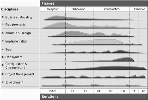
FIGURE 1.1 The emphasis of the different disciplines during the four phases of the Rational Unified Process (RUP®).2, 3
Inception is the first phase of UP, in which the main requirements are discovered and the extension of the system is understood. The output of this phase usually consists of a preliminary conceptual model (Section 3.6); a requirements document, usually in the form of a list of high-level use cases (Section 3.3) and supplementary specifications (Section 3.5.8); and a development schedule based on the use case list (Section 4.3). Additionally, a list of high-importance risks and their mitigation plans may be created, as well as other plans attending the special needs of the project. But those aspects are out of the scope of this book, which will concentrate on modeling techniques, not management. Only iteration planning based on high-level use cases is presented in detail.
The Elaboration phase includes a more detailed requirements analysis, which is performed by expanding the use cases, that is, writing the sequence of steps that characterizes each of their possible flows. The conceptual model is refined after each use case is expanded. Depending on the priority of the use cases, it is expected that the number of changes applied to the software architecture decreases as the project proceeds during Elaboration.
During the Construction phase most of the code production and test activities are performed. It is expected that the Elaboration phase produces an architecture sufficiently stable so that its refactoring will be minimized during this phase.
The Transition phase consists typically of the final tests and the delivery of the system to its users including possibly its installation and data migration. During this phase, the system will be deployed, possibly replacing an existing system (manual or automatic).
The Elaboration and Construction phases are performed in iterations. An iteration may have as an objective developing one or more use cases, implementing change requests, or mitigating selected risks. During an iteration, use cases are expanded and the information learned from them is incrementally incorporated in the product. It is expected that the Elaboration phase deals with the major risks of the system, as well as with the more complex or risky use cases that affect the system architecture significantly. On the other hand, the Construction phase concentrates on producing code for the whole application and implementing change requests.
UP is usually understood as a prescriptive process. But it may also be performed as an agile method, with few artifacts. Two popular agile implementations of UP are AUP4 (Ambler & Jeffries, 2002) and OpenUP5 (Kroll & MacIsaac, 2006). An agile process is one that prioritizes:6
• People and iterations over tools and processes.
• Working software over comprehensive documentation.
• Customer collaboration over contract negotiation.
• Responding to change over following a plan.
In order to obtain such agility, all documentation must be directed to software production. Each activity performed by the developer must have a very clear goal and a precise use, aiming always toward the production of code that meets the requirements in the best way possible and in the shortest reasonable time. Software is designed with two goals in mind: understanding client needs, and producing a viable solution to those needs. In order to help people adequately communicate their needs and solutions, different artifacts, such as diagrams, may be created; diagrams are more useful when they allow code to be automatically generated from them.
1.5 The process so far
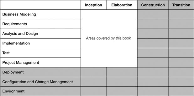
At the end of each chapter, a table shows which analysis and design activities have been covered by the book, highlighting those that were covered by the current chapter. This initial chapter is a general view of the Unified Process. Only the Inception and Elaboration phases are addressed in this book, and only the disciplines of business modeling, requirements, analysis and design, implementation, test, and some aspects of project management are addressed.
1.6 Questions
1. What are the four fundamental principles of the Unified Process?
2. What is the goal of each of the four phases of the Unified Process?
3. How do the phases of UP differ from waterfall's phases?
1http://www.uml.org/.
2RUP (Rational Unified Process) is the oldest and most known implementation of the Unified Process.
3Source: http://www.ibm.com/
4http://www.ambysoft.com/unifiedprocess/agileUP.html
5http://epf.eclipse.org/wikis/openup/index.htm
6http://agilemanifesto.org/
All materials on the site are licensed Creative Commons Attribution-Sharealike 3.0 Unported CC BY-SA 3.0 & GNU Free Documentation License (GFDL)
If you are the copyright holder of any material contained on our site and intend to remove it, please contact our site administrator for approval.
© 2016-2026 All site design rights belong to S.Y.A.