Object-Oriented Analysis and Design for Information Systems: Modeling with UML, OCL, and IFML (2014)
CHAPTER 12
Interface Tier Design with IFML
This chapter shows how to design a web interface for an information system using the Interaction Flow Modeling Language (IFML). Initially, the information view components of IFML are presented. They are used in connection with the design class diagram to manage the presentation of information. The integration of view components and flows into containers such as pages and areas is presented as well as some interface design patterns. Operation components may also be used in connection with view components to define basic operations over objects. The chapter concludes with the presentation of a complete CRUD interface modeled in IFML and a high-level design for a system use case.
Keywords
IFML; Interaction Flow Modeling Language; user interface; user interface pattern; view component; web navigation; web page
Key Topics in this Chapter
• The interaction flow modeling language (IFML)
• View components
• Hypertext organization
• Web page patterns
• Operations in IFML
12.1 Introduction to interface tier design
The interface tier design of a system depends fundamentally on the detailed use cases or system sequence diagrams, because the interface must allow a user to follow all use case flows. Design class diagrams and contracts may be very useful as well.
During interface design the nonfunctional requirements that were annotated with the use cases should be revised again, because they may contain indications on how to design the use case interface.
The Interaction Flow Modeling Language (IFML) is an extension of UML for modeling data intensive user interfaces. It is an evolution of WebML (Ceri, Fraternali, Bongio, Brambilla, Comai, & Matera, 2003). IFML is being adopted as an OMG standard.1
This chapter intends to present the most fundamental concepts of IFML, and its modeling potential. More information may be found at the official site of the language.2 As IFML is still evolving as a pattern, the reader may expect to find some discrepancies between this text and the current specification of IFML, which may have changed after this book was published.
12.2 Interaction flow modeling language (IFML)
IFML is suitable for modeling interfaces, especially those that make intensive use of data such as information systems. The development method proposes the building of five models in order to define an application:
• Structural model: This represents the data structure and data organization. Ceri et al. use the entity-relationship diagram to define the structural model. However, the UML class diagram (Chapters 6 and 7) may be used for the same purpose.
• Derivation model: This was originally proposed for modeling data that can be calculated from other data. The derivation model may be understood as the set of definitions of derived attributes and associations that usually are defined in the conceptual model and may be written in OCL (Sections 6.2.3 and 6.4.3).
• Composition model: This includes the definition of containers as aggregates of basic view components (Section 12.3), pages (Section 12.4), and areas (Section 12.6.2).
• Navigation model: Where the flows between pages and view components are defined (Sections 12.5 and 12.6).
• Presentation model: Where the positioning of view components at the interface and their appearance are defined.
This chapter addresses particularly the composition and navigation models. The structural and derivation models were already discussed in Chapters 6 and 7). For the presentation model, the WebRatio® tool3 provides the use of XSL Style Sheets.4 The code generator of the tool uses these presentation rules to produce pages according to the design produced with other tools. For the examples presented in this chapter, the standard interfaces rendered by the tool, without the use of styles, are shown. Even names of fields were left identical to the names of class attributes in the aim of promoting understandability instead of graphic quality.
12.3 View components
View components are the most basic elements in an IFML specification. View components may be directly associated to design classes and allow the viewing of instances of these classes.
There are many types of view components in IFML. Some examples are:
• Details: Displays information about a single object.
• Multiple details: Displays information about a collection of instances of the same class.
• Simple list: Displays multiple instances of a class in the form of a list.
• List: An enhancement of simple list that allows scrolling and dynamic sorting.
• Checkable list: A list that allows multiple selection.
• Hierarchy: Displays multiple instances of different classes organized in a hierarchy, such as master-detail or whole-part.
• Recursive hierarchy: Displays multiple instances of a single class that are organized hierarchically, such as organizational structures.
• Scroller: Allows the typical scroll operations on a sequence of objects.
• Form: Allows form-based data entry.
• Multiple form: Similar to form, but allows editing multiple objects at once.
• Message: Allows printing messages on the page.
• Calendar: Shows a perpetual calendar.
There are other view components and new ones may be defined. This chapter presents details on the most fundamental ones. For each kind of view component a graphical definition is presented, as well as the possible appearance of the web page rendered by WebRatio for the definition. All examples are based on the DCD of Figure 12.1.
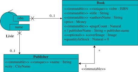
FIGURE 12.1 Reference design class diagram.
12.3.1 Details
The details view component presents information about a single object of a given class. It is defined by the following properties:
• A name, which is chosen by the designer.
• An entity or source of data, which is usually a class from the design class diagram.
• Display attributes, which is a list of attributes from the class to be displayed when the details view is rendered.
Most view components such as details also allow for the definition of one or more conditional expressions that work like selectors or filters over the set of instances to be shown. There are three kinds of conditional expressions:
• Key condition: Each object in the data model is identified by an OID (Object IDentifier) – an attribute that is unique, mandatory, and immutable. It must not be confused with any of the attributes of a conceptual class, even the ones stereotyped with ![]() unique
unique![]() and
and ![]() immutable
immutable![]() , such as ISBN and Social Security number. The OID is an internally generated code that corresponds to the primary key of an object. OIDs cannot be known or updated by the user. A key condition allows one to select one or more instances from a given class based on the value of its OID attribute.
, such as ISBN and Social Security number. The OID is an internally generated code that corresponds to the primary key of an object. OIDs cannot be known or updated by the user. A key condition allows one to select one or more instances from a given class based on the value of its OID attribute.
• Attribute condition: This allows for the selection of one or more instances based on the values of their attributes. Operations such as greater than, equal, or contains may be used to compare the value of an attribute to a given parameter.
• Relationship role condition: This allows for the selection of one or more instances based on their association links.
Figure 12.2 presents a details view component intended to show data about an instance of a book for a given ISBN. The conditional expression isbn=0517149257 determines which instance is shown. If such an instance does not exist, then no information is rendered by that component.
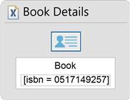
FIGURE 12.2 A details view component with a simple attribute condition.
The attributes property usually does not appear in the graphical representation. If a modeling tool is being used, this property may probably be accessed by browsing the component. As an ISBN is an attribute that is unique and mandatory, it is safe to assume that no more than one book is presented by this details view.
Figure 12.3 shows a possible web rendering for the details view component shown in Figure 12.2.
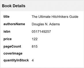
FIGURE 12.3 A possible rendering for a details view component with all attributes of class Book.
The final rendered page may vary, because it is possible to add style definitions so that interfaces with different designs and appearance are produced.
If the details view component of Figure 12.2 is changed to show only the title and authorsName attributes, it would produce the rendered result shown in Figure 12.4.

FIGURE 12.4 A possible rendering for a details view with fewer attributes selected.
12.3.2 Multiple details
Multiple details presents a group of instances of a single class at once. Besides the three properties already shown for details view components, they add new optional properties:
• Sort attributes: Defines the attributes used for sorting the instances.
• Max results: Specifies the maximum number of instances to be retrieved. By default, all instances are retrieved.
• Distinct: Specifies that duplicate elements will not be shown more than once.
Multiple details also allows for the definition and use of conditional expressions in order to select which elements are to be shown. Figure 12.5 presents an example of multiple details.
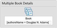
FIGURE 12.5 A multiple details view component.
Figure 12.6 presents a possible rendering for the multiple details of Figure 12.5 considering that only three books satisfy the conditional expression and that sorting is by title.
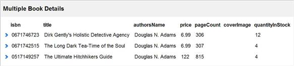
FIGURE 12.6 A possible rendering for a multiple details view component.
As opposed to the details view component that shows only one instance at a time, multiple details presents all the objects that satisfy the conditional expression.
If it is necessary to use more than one attribute to determine the objects to be presented by the component, then a combination of conditional expressions may be used. This combination may use the operands and and or. Figure 12.7 presents a multiple details view component that shows instances that have pageCount higher than 100 and price lower than US$150.00.
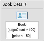
FIGURE 12.7 Multiple details view with a composite conditional expression.
12.3.3 Simple list
The simple list presents one or more attributes of a set of instances of a class in the form of a list. While multiple details are normally used to visualize the details of many objects in the same page, a simple list and its variations are used when a list or menu is necessary for the user to select one or more elements and perform actions with them. The properties of simple lists are the same as those of the multiple details view component.
It is possible, for example, to define simple lists for selecting books based on their titles. Figure 12.8 presents the view component for a simple list of book titles, and Figure 12.9 shows a possible rendering. The absence of a conditional expression in the simple list view component means that all instances of Book are listed.

FIGURE 12.8 Simple list.
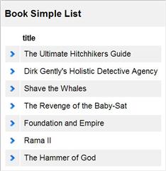
FIGURE 12.9 Possible rendering of a simple list.
12.3.4 List
A list is an enhanced version of the simple list that allows one to scroll elements and dynamically reorder them by a simple click on the head of the respective attribute column. Besides the properties already defined for simple lists, it includes the following specific properties:
• Sortable: A Boolean attribute that when true defines that the list may be dynamically sorted.
• Default sort attributes: If the list is sortable it defines the sorting attributes that may be selected by the user to sort the list and also the default sorting criteria when the list is rendered for the first time.
• Sort history size: Specifies how many sort actions from the user must be remembered by the list.
• Checkable: If true, a check box is rendered for each element of the list.
• Block factor: Specifies how many elements are shown at a time. If unspecified or set to −1, all elements are shown. If the block factor is defined, then scrolling commands are rendered for the list.
Figure 12.10 shows the IFML view component for a list. This list is defined for the Book class with three attributes: authorsName, title, and price. The block factor is defined as 3. Figure 12.11 shows a rendered version of that list.

FIGURE 12.10 List.
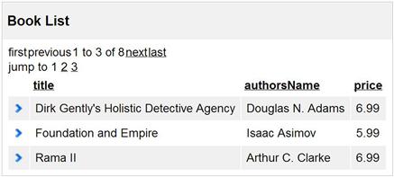
FIGURE 12.11 Possible rendering for a list.
Observe at the top of Figure 12.11 the commands to scroll the list from the first to the last group of three elements. Currently the first three elements are being shown, sorted by their title.
If the user clicks one of the links at the top of each data column, then the elements on the list are rearranged and sorted by that column. If the user clicks, for example, on authorsName, the lines will be sorted by the author’s names, as seen in Figure 12.12.
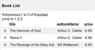
FIGURE 12.12 Rendering of Figure 12.11 after a user action.
Notice that the elements shown are different because the entire list is sorted again and the elements that are being viewed are the first three.
12.3.5 Checkable List
The checkable list allows the user to select a set of elements from a list. Otherwise it is very similar to a simple list. Figure 12.13 presents the IFML definition of a checkable list and Figure 12.14 presents its rendering.

FIGURE 12.13 A checkable list.
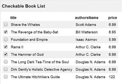
FIGURE 12.14 Rendering for a checkable list.
While simple lists allow the selection of only one object at a time, checkable lists allow the selection of any quantity of objects.
12.3.6 Forms
A form is used for data input. It is very useful for creating new instances, and also to provide parameters for searches, queries, and commands.
A form is composed of a set of fields. Each field holds an alphanumeric value. There are text fields, selection fields, and multiselection fields.
A form may or may not be associated to a class. If it is associated to a class, then its fields may be associated to the attributes of a class.
Forms that are used to collect parameters for a query or command usually do not need to be associated to classes. For example, a form that collects keywords for searching books does not need to be associated to any class.
The fields of a form have the following properties (among others):
• Name: The name of the field, given by the designer.
• Attribute: If the form is associated to a class, then the field may be associated to one of its attributes.
• Content type: Defines the type of the field, which may be string, text, blob, or url.
• Preloaded: The field may be preloaded with values that are shown to the user when the form is rendered.
• Modifiable: Defines whether the initial value of the field may be changed or not. The default is that a field value may be changed.
Figure 12.15 presents a form that is associated to the Book class, and Figure 12.16 presents its rendering.

FIGURE 12.15 A form.
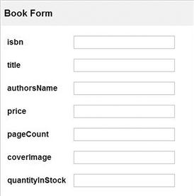
FIGURE 12.16 Rendering of a form.
12.3.7 Hierarchies
Hierarchies are used to show object dependencies with two or more levels. They are useful, for example, for showing objects that are related by a one-to-many association such as Publisher and Book, or whole-part associations such as Book and Chapter. Figure 12.17 shows a definition of a two-level hierarchy with Publisher at the top and Book at the second level.
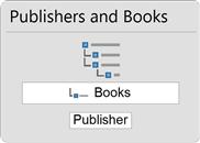
FIGURE 12.17 A hierarchy.
The second level usually defines a role-based conditional expression. In the example, the role-based conditional expression defines that only books that are linked to a given publisher are shown below it. In the absence of a conditional expression, all books would be shown below each publisher, but that is not the case now.
Figure 12.18 shows a rendering for the hierarchy of Figure 12.17 with books linked to their respective publishers.
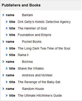
FIGURE 12.18 Rendering of a hierarchy.
There are situations that require the application of the organizational hierarchy pattern explained in Section 7.8, where a concept has subconcepts that belong to the same class, which may be recursively nested. For these cases, IFML provides a recursive hierarchy view component. Figure 12.19 shows a recursive hierarchy defined for the OrganizationalStructure class shown in Figure 7.15.
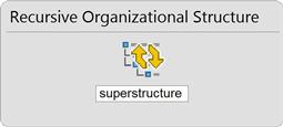
FIGURE 12.19 A recursive hierarchy.
The definition and rendering of a recursive hierarchy is similar to that of a normal hierarchy. The only differences are that the detail class and the master class are the same and the number of levels is undetermined.
12.4 Pages
Pages are the interface elements that are effectively accessed by the user. Typically, a page contains one or more view components and possibly some other pages.
The IFML representation of a page contains a name and an optional set of included view components and subpages. For example, Figure 12.20 presents a page that contains a list of publishers and a list of books, and Figure 12.21 presents its rendering.
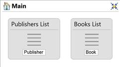
FIGURE 12.20 A page with two view components.
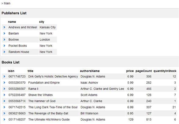
FIGURE 12.21 Rendering of a page with two view components.
The ![]() symbol in Figure 12.20 indicates that this page is a homepage, that is, the initial page of an application. The other symbol in the upper-right corner of the page does not have any special meaning in IFML; it is just a tool-specific command to highlight and obscure graphic elements.
symbol in Figure 12.20 indicates that this page is a homepage, that is, the initial page of an application. The other symbol in the upper-right corner of the page does not have any special meaning in IFML; it is just a tool-specific command to highlight and obscure graphic elements.
The view components that appear inside the page in Figure 12.20 are independent of each other because there are no flows between them.
By default, view components defined in the same page are rendered one on top of the other, and occupy the entire width of the page. But it is possible to use the presentation model, as mentioned before, to define view components in different positions and sizes. The presentation model consists basically of a grid in which the view components are positioned and dimensioned inside a page. In the example of Figure 12.22 the view components were placed side to side.
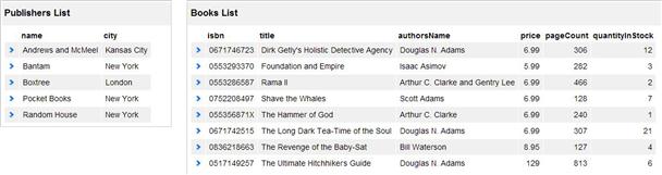
FIGURE 12.22 A different rendering arrangement for the page shown in Figure 12.21.
12.5 Flows
A flow is an oriented connection between two pages or view components. Flows may be used not only to define navigation possibilities between pages, but also to define data dependencies. For example, selecting an element in a list view component may cause information about the element to appear in a details view component. This can be accomplished by defining a flow from the list to the details.
12.5.1 Normal navigation flow
Normal navigation flows are a type of flow that is rendered as a clickable link in its origin page or view component. When the link is clicked it navigates to the destination page or view component. It is represented by an arrow.
Figure 12.23 shows an example of a normal navigation flow between two pages. The resulting rendering of the Publishers page contains a link to the Books page (at the right top corner of Figure 12.24).
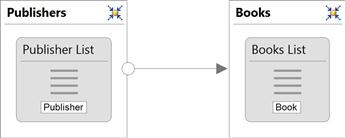
FIGURE 12.23 A normal navigation flow between pages.
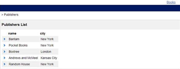
FIGURE 12.24 Rendering of a normal navigation flow as a link.
We can see in Figure 12.23 that the flow is not attached to the view components, but to the pages. Therefore, the link will be rendered only once in the page where the list of books is visualized.
If the flow had its origin at the list view component as in Figure 12.25, then each line in the list would have an individual link to the Books page.
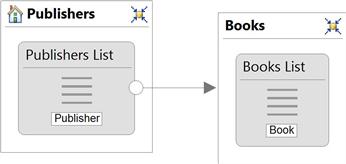
FIGURE 12.25 A flow from a view component to a page.
Figure 12.26 shows how the model in Figure 12.25 would be rendered.
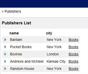
FIGURE 12.26 Rendering a link for each element of a list.
This list is still just a set of links that have the same effect: navigating to the Books page. The following sections show how this kind of flow can be used to transport information from one view component to another, making it possible, for example, to visualize only the books of a given publisher.
12.5.2 Data flow
Data flows are a kind of flow that is not rendered, but that define data dependency between view components.5 Dashed arrows represent data flows.
Data flows do not define navigation between view components. They are used to get values from one component without navigating from it. They are particularly useful when a component needs data from more than one component. The following sections present examples of data flows that get data from different sources.
12.5.3 Parameter binding
A parameter binding is a piece of information that is transmitted from the origin to the destination of a flow. A parameter binding has a name and a value, which is obtained at its origin component.
A flow may have a multiple parameter binding, passing a set of values instead of a single one.
Usually, object keys or attribute values are passed by parameter bindings. By default, a flow from a view component binds the key of the selected object at the origin component and takes it to the destination, where it can be used, for example, by a conditional expression.
In previous examples only constants were used in conditional expressions to select the elements to be shown in view components such as lists and details. Now, with flows and parameter binding, it is possible to use a view component to define which elements are shown in another view component.
The IFML diagram shown in Figure 12.27 shows a list of books with a flow to a details view component. The details view has a key condition [oid=?]. As the key of the selected book at the list is bound to the flow that goes to the details view, only that book is shown when the details view is rendered.
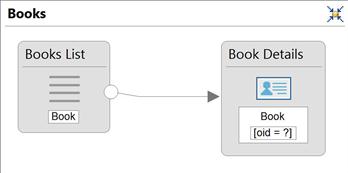
FIGURE 12.27 A normal navigation flow connecting two view components.
When the user selects a book in the list, by clicking the respective link, the details view presents information about the book. Figure 12.28 shows the state of the page when the link associated to the first book is clicked.
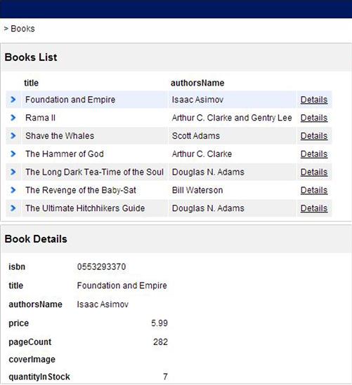
FIGURE 12.28 Rendering of the model of Figure 12.27 when the first book is selected in the list.
Parameter binding may also be used to associate a form to another view component. For example, the form may provide a search field, and a list would present only the elements that satisfy some search criteria.
Figure 12.29 shows an example where a search field is used to find the books of a given author. The user may type the author’s name or part of it in the search field, and the results are shown in the Books list.
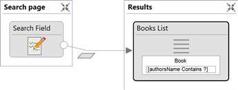
FIGURE 12.29 A flow that transports data from a form to a list.
The parallelogram that is next to the flow indicates that this flow has a parameter binding that is not the default object key.
In the rendering shown in Figure 12.30, the user just typed “Clarke” in the search field, and the results produced are shown in Figure 12.31.
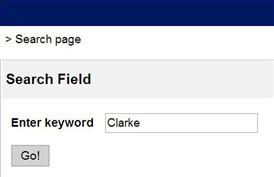
FIGURE 12.30 Rendering of the model of Figure 12.29 before the search is performed.
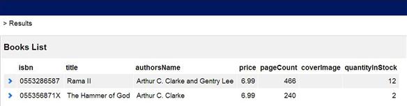
FIGURE 12.31 Rendering of the model of Figure 12.29 after the search is performed.
12.5.4 Multivalued parameter binding
It is possible to define flows from multiple-choice components such as checkable lists. In these cases, a parameter binding passes a set of values (checked elements keys, for example).
If a checkable list is linked to a multiple details view like in Figure 12.32, the user may select a number of elements on the checkable list as in Figure 12.33 and press the button on the bottom to navigate to the page that shows the details of the selected books only (Figure 12.34). The multiple details view has a key condition that states that only books whose OID belong to the set that is bound to the flow are shown.
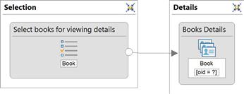
FIGURE 12.32 A flow with multivalued parameter binding.
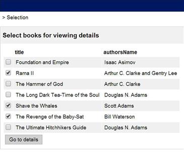
FIGURE 12.33 Rendering of the model in Figure 12.32 before clicking on the button.
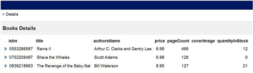
FIGURE 12.34 Rendering of the model in Figure 12.32 after clicking on the button.
12.6 Hypertext organization
View components, flows, and their organization inside pages constitute the most local interface models. However, it is also necessary to create wider models for an interface, including groups of interrelated pages, navigation regions, landmarks, and so on. This kind of model is described in this section and is referred to as hypertext organization.
12.6.1 Site views
A site view is a package that contains an entire application that may be delivered for users. It usually contains a group of areas (see next section) and pages for the application. Figure 12.35 presents an example of a site view with a page (Main) and two areas (Administrative and Customer).
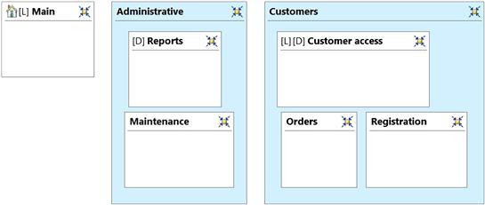
FIGURE 12.35 A site view.
This example has not yet been fully developed, though. Only the top-level structure is shown in Figure 12.35.
12.6.2 Areas
A site view may be organized in areas. Areas and pages are referenced in IFML as containers. Areas are groups of containers that have affinities, such as, for example, a set of functions related to a given user goal.
In the IFML model of Figure 12.35, the areas appear as shadowed rectangles. Areas provide hierarchical organization to a site view.
12.6.3 Home, landmark, and default
In Figure 12.35 some containers have special properties:
• [H] or ![]() indicates the homepage. The homepage is the initial page of an application. When a user accesses the website she will access the home page by default. Areas do not have this property.
indicates the homepage. The homepage is the initial page of an application. When a user accesses the website she will access the home page by default. Areas do not have this property.
• [D] indicates the default page of an area. When a user navigates to a given area, she will land on the default page. Thus, the default page is a kind of “homepage” for a specific area. Areas do not have this property.
• [L] represents a landmark page or area. This means that the page or area is directly accessible from any other page included in the same area. Thus, it avoids the need to create lots of flows to pages that must be accessed from many places.
Only one homepage may exist for a given site view and only one default page for a given area. However, any number of landmark areas or pages may exist.
12.7 Web Interface Patterns
Most web interface patterns presented in this section are adapted from Ceri et al. (2003) and Tidwell (2005).
12.7.1 Cascade Index
A cascade index is a sequence of menus based on lists that eventually reaches a details view. For example, a user could begin by selecting a publisher. Then, the user could select a book from a publisher’s list, and finally access the book details. Figure 12.36 illustrates that pattern.
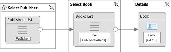
FIGURE 12.36 Example of a cascade index.
In the diagram of Figure 12.36, as the parameter bindings are default, the flows carry the OIDs of the selected elements. Those OIDs may be used by the conditional expressions at the destination view component to define which elements are to be shown.
The view component Books List uses a role-based conditional expression that shows only the books linked to the publisher whose OID is bound to the entry flow that comes from Publishers List.
Notice that the Books List has a conditional expression that is based on the role PublisherToBook, that is, only books linked to the publisher at the origin of the flow are shown by Books List.
The Book details view shows the complete information of the book selected in Books List. The selected book’s OID is bound to the flow that comes from Books List to the details view. Figures 12.37 to 12.39 show a sequence of rendered interfaces that illustrates that pattern. In Figure 12.37 a publisher may be selected. In Figure 12.38, after selecting the second publisher, one of its books may be selected. Finally in Figure 12.39 the third book was selected and its details are shown.
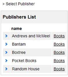
FIGURE 12.37 Rendering of Publishers List.
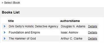
FIGURE 12.38 Rendering of Books List.
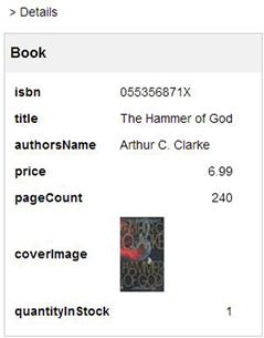
FIGURE 12.39 Rendering of Book details.
One variant of this pattern consists of showing some data from the object selected in one of the intermediary lists. Figure 12.40 illustrates that situation.
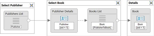
FIGURE 12.40 Cascade index with intermediary data presentation.
There, when a publisher is selected, the interface shows the publisher’s details and a list of books for further selection. Notice that in the intermediary page Publisher Details is connected to Books List by a data flow. It is not necessary for the user to navigate from Publisher Details to its list of books: both view components are shown at the same time when the Select Book page is accessed. Figure 12.41 shows how the intermediary page could be rendered.
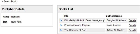
FIGURE 12.41 Rendering of the intermediary page of a cascade index with intermediary data.
12.7.2 Filtered index
In some cases it may be necessary to show a list with selected elements. For example, if the bookstore has thousands of books in its catalog, it would not be feasible for a user to simply browse for a book in that list. A filtered list could be used instead, for example, asking the user to provide a keyword in order to show a reduced book list.
This pattern is accomplished by a connection between a form, a list, and a details component, as shown in Figure 12.42.
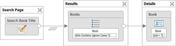
FIGURE 12.42 An example of a filtered index.
As the results are shown by a list (not a simple list), a scroll block factor may be defined as well as the possibility of dynamically sorting the results. Furthermore, a maximum number of results may be defined for this list so that unnecessarily large lists are not presented.
12.7.3 Guided tour
A guided tour is a pattern that allows one to visualize details of a set of objects one at a time by using scroll operations. It is implemented by using a scroller component with blockFactor 1 linked to a details view, as seen in Figure 12.43.
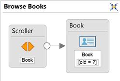
FIGURE 12.43 Specification of a guided tour.
Figure 12.44 shows a rendering of that specification where the fifth of eight books was selected by the user.
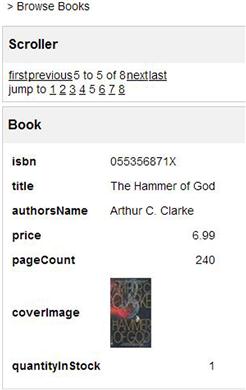
FIGURE 12.44 Rendering of a guided tour.
12.7.4 Viewpoints
Sometimes, it may be interesting to present different faces of certain objects in different moments. For example, summarized data about a book may be presented by default, but that data may be expanded or contracted again at the user’s will.
In order to implement the viewpoints pattern, two or more details components may be defined for the same class, with different sets of attributes. Flows may be defined between the different components to allow the user to change from one view to another, as shown in Figure 12.45.
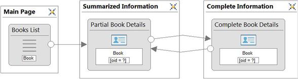
FIGURE 12.45 Specification of viewpoints.
Figure 12.46 shows the appearance of the summarized viewpoint and Figure 12.47 shows the complete information viewpoint.

FIGURE 12.46 Summarized viewpoint.
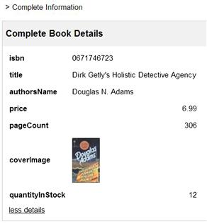
FIGURE 12.47 Complete information viewpoint.
12.7.5 Overview plus detail
The overview plus detail pattern is very common in applications such as email browsers, but it can be applied to a variety of other situations. The idea is to have in the same page a scrolling list of elements and the details view of one selected element in a region next to the list.
Figure 12.48 shows an IFML definition that uses this pattern with a list with block factor 3 and a details view component linked to it by a flow.
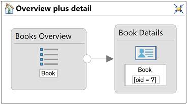
FIGURE 12.48 Specification of an overview plus detail pattern.
Figure 12.49 shows a rendering for the page specified in Figure 12.48.
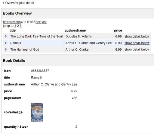
FIGURE 12.49 Example of rendering of a page using the overview plus detail pattern.
12.7.6 Top-level navigation
Top-level navigation is a frequent pattern in web pages where a top-level menu allows access to different areas of the site. The example in Figure 12.50 illustrates top-level navigation being defined by a set of landmark areas, each containing one page (they could contain more pages if needed).
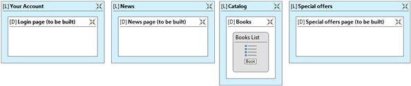
FIGURE 12.50 Example of specification of top-level navigation.
For the example, only the third area was partially defined. A rendering of that model is shown in Figure 12.51 where the third area, “Catalog,” is selected from the top menu showing the default page Books.
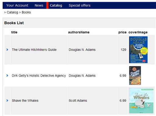
FIGURE 12.51 Example of rendering of a page using top-level navigation.
A variation of this pattern is menu-based top level navigation. This may be accomplished by adding a set of landmark pages to each of the top landmark areas, as shown in Figure 12.52.
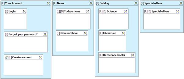
FIGURE 12.52 Example of specification of menu-based top-level navigation.
Figure 12.53 shows the rendering when the mouse is positioned over the menu item “Catalog.”

FIGURE 12.53 Example of rendering of a page using menu-based top-level navigation.
12.8 Modeling operations in the interface
IFML allows basic operations to be modeled by using operation components that allow for the creation, deletion, update, connection, disconnection, and reconnection6 of instances. These components perform most of the basic operations that were presented in Section 8.5. Figure 12.54 shows the graphical representation of those operations.
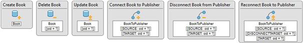
FIGURE 12.54 Operation components: create, delete, modify, connect, disconnect, and reconnect.
The operation components do not hold or render information; they just process information. Therefore, they are represented graphically outside the pages.
Every operation component should have at least one input flow. Sometimes all the information the operation needs is obtained from a single view component, but sometimes more than one view component may be necessary to supply all the data needed by an operation.
Operation components have special output flows. Two different kinds of output flows exist for operations:
• OK flow, which defines where the focus goes when the operation is successfully performed for every object.
• KO flow, which defines where the focus goes when the operation fails for at least one of the objects affected by it.
The operation components are based on classes or associations that are their data sources. Create, delete, and update operations are defined over a single class, while connect, disconnect, and reconnect are defined over an association, and therefore they have a source and a target class.
For example, a delete operation could be defined over the Book class as in Figure 12.54; this operation would be responsible for deleting instances of Book.
A connect operation, on the other hand, would be defined over an association such as BookToPublisher, as shown in Figure 12.54. Therefore, it would be responsible for connecting (adding links between) instances of the Book class (source) and the Publisher class (target).
12.8.1 Create operation
The create operation creates new instances of a given class. A navigation or data flow may be used to provide initialization data for the new instance. Usually, the initialization data are obtained from a form based on the same class. A flow from the form to the create operation passes the values for all necessary attributes except for the OID, which is generated automatically by the create operation. For example, Figure 12.55 shows a structure for creating instances of Book.
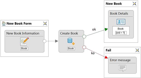
FIGURE 12.55 Example of application of a create operation.
Figure 12.56 shows the rendering of the form that is the origin of the flow to the create operation. The flow is rendered as the Save button.
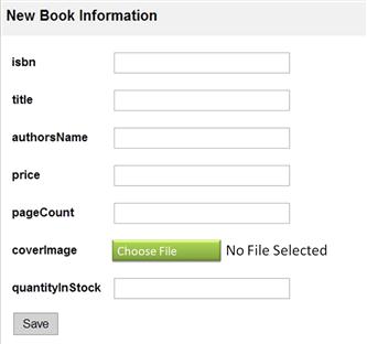
FIGURE 12.56 Rendering of a form with a flow to a create operation.
As we can see, the user may type in the form the initialization values for the new book. The flow from the form binds the data and takes the data to the create operation. The create operation then creates the new instance and defines its attributes with the values received from the flow.
If the operation is successful, then the OK flow is followed to a details component that shows the newly created book. The OK flow binds automatically the OID of the new book so that the conditional expression at the details may be used to define which book to present.
If the operation fails, the control goes to an error page following the KO flow.
12.8.2 Delete operation
The delete operation may be performed over one or more objects that satisfy the conditional expression defined for it.
The delete operation may be used in conjunction with a list (any kind of list), where the user may select the object(s) to be deleted. Figure 12.57 shows an example where the user selects a book to delete from a simple list. Notice that the selector of the delete operation is based on the book’s OID, which is received as a parameter from the input flow.
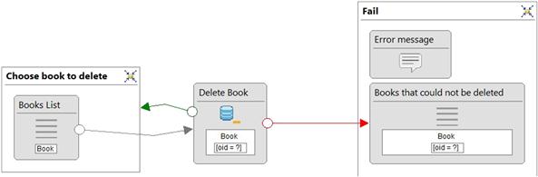
FIGURE 12.57 A delete operation being activated from a list.
This page may be rendered as in Figure 12.58, where the word “delete” corresponds to the flow name.
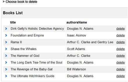
FIGURE 12.58 Rendering of a simple list associated to a delete operation by a flow named “delete.”
When all objects that qualify to be deleted are really deleted, the OK flow is followed. When at least one object cannot be deleted, the KO flow is followed and passes as a parameter binding the OIDs of the objects that could not be deleted. Thus, the KO flow could, for example, lead to a list or a multiple details view where the objects that could not be removed are shown, as seen in Figure 12.57.
12.8.3 Update operation
An update operation contains a selector for one or more objects of the same class and a set of assignments for updating the attributes of those objects. Usually, new values for attributes are received by normal navigation or data flows.
Figure 12.59 shows how to use an update operation to change the price of an existing book.
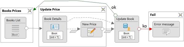
FIGURE 12.59 An update operation being used to change the price of a book.
On the Book Prices page, a book is selected from a list (Figure 12.60). Then a new page (Update Price) shows details of the book and a field preloaded with the old price. The user may change that value and update it by pressing “Save” (Figure 12.61).
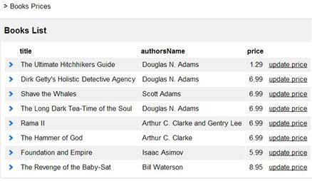
FIGURE 12.60 Rendering of the Book Prices page.
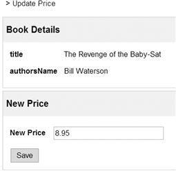
FIGURE 12.61 Rendering of the Update Price page.
The old price is loaded in the New Price field by a data flow from Book Details. The update operation is activated by the navigation flow that is rendered as the Save button on the Update Price page. That navigation flow has a parameter binding that passes the new price of the book from the respective field in the New Price form to the update operation. Other attributes of the book, including its OID, are received by a data flow from Book Details.
In Figure 12.59, the OK flow from the update operation leads back to the list on the Book Prices page, where the new price may be visualized. The KO flow leads to an error window. Again, the OK flow is followed when all objects qualified by the conditional expression are changed. If at least one object cannot be updated, the KO flow is followed with the set of OIDs of the objects that could not be updated as binding parameters.
12.8.4 Connect, disconnect, and reconnect operations
The connect, disconnect, and reconnect operations have an association as a source of data. The connect and disconnect operations have two conditional expressions: one for the origin role and the other for the target role of the association. The reconnect operation may be understood as a combination of the former ones. It has three conditional expressions: one for the origin role, another for objects in the target role to be disconnected, and a third for objects in the target role to be connected to the source objects.
The connect, disconnect, and reconnect operations may add, remove, or replace links between sets of objects. If, for example, five objects satisfy the source conditional expression and three objects satisfy the target conditional expression, then a connect operation would create 15 links: each of the five origin objects will be linked to each of the three target objects.
The example in Figure 12.62 shows how a link between a book and a publisher may be created. First of all, the link is mandatory from the book to the publisher. Thus, it is not possible simply to get a list of books and a list of publishers and choose which ones should be linked. A link between a book and a publisher must be created as soon as the book is created. Furthermore, that link is immutable and cannot change later.
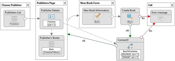
FIGURE 12.62 IFML model showing an interface in which books may be created and linked to publishers.
On the first page, Choose Publisher, there is a simple list of publishers. The user may choose one and be taken to Publisher Page. There, the publisher’s details and a list of books already linked to it are shown. Notice that Publisher Details has a key condition and a flow from Publishers List, and therefore, it shows the publisher selected in the list. The Publisher’s Books list has a data flow coming from Publisher Details and a role-based conditional expression so that only books that are linked to the publisher of Publisher Details are shown. Figure 12.63 shows the Publisher Page rendered after the publisher “Bantam” was selected from the list.
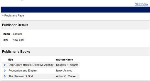
FIGURE 12.63 Rendering of the Publisher Page.
From the Publisher Page the user may navigate to the New Book Form by using a normal navigation flow between both pages, which is rendered as the New Book link. In this page the user may fill in the form with information about the new book, which will be automatically linked to the publisher presented in the Publisher Page. Initially the create operation creates the new instance of book. Its OK flow leads to a connect operation that is based on the association BookToPublisher. The flow that comes from the create operation has the new book key as a parameter binding; that key is used in the source conditional expression. The publisher is the target and it is obtained by a data flow coming from Publisher Details.
If the connect operation is successful, it returns focus to the Publisher Page, where the new book can be seen in the list of the current publisher’s books. If the create or connect operation fail then focus goes to a page with an error message.
However, the design shown in Figure 12.62 is not safe. If a book is created and the connect operation fails, that book would remain inconsistent regarding its definition. IFML allows a transaction to be defined as a group of operations. Figure 12.64 shows an operation group being defined to include both the create and connect operations. As the operation group may be defined as a transaction ([T]), either all of the operations inside the group succeed or the whole group fails. In that case a single KO flow from the group is followed.
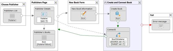
FIGURE 12.64 A safer design for Figure 12.62 using an operation group.
12.9 IFML models for CRUD operations
This section shows step-by-step how to implement a CRUD-style interface for managing information about publishers using IFML view components and operations.
The CRUD main page, Manage Publishers, presents a list of existing publishers. The creation of a new publisher is initiated by clicking on a link on the main page that gives access to a new page with a form. If the creation of a new publisher is successful, control returns to the main page, and the new publisher appears in the list. If there is an error, control goes to an error page, from which it is possible to return to the main page (Figure 12.65).
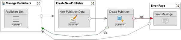
FIGURE 12.65 Defining an interface for “create”.
The second operation of a CRUD, retrieve, is the query that allows the visualization of all attributes of a given publisher. This query may be modeled by a flow from the main list that leads to a page with a details view component, as shown in Figure 12.66.
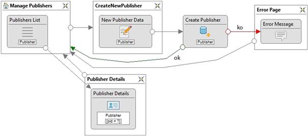
FIGURE 12.66 “Create” and “retrieve” defined.
The third operation, update, allows a publisher to be selected in the main list, and the attributes of the selected book are used to fill the fields of a form with Publisher as the source class. There they can be edited by the user and saved as shown in Figure 12.67.
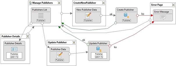
FIGURE 12.67 “Create,” “retrieve,” and “update” defined.
Finally, the operation for deleting a publisher is added, as shown in Figure 12.68. A delete operation may be accessed from the main list.
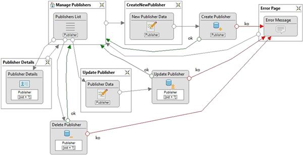
FIGURE 12.68 Complete CRUD interface specification.
Figure 12.69 shows the rendering of the main page of the CRUD of Publisher, as defined in Figure 12.68. At the top of the page, we can see the link for creating a new book, and just below is the main list, where the options for retrieving, updating, and deleting each publisher are available.
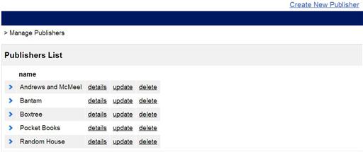
FIGURE 12.69 Main window for the CRUD for Publisher.
Figure 12.70 shows the rendering for the retrieve page, which is accessed by selecting the details option for the third publisher on the main page list. The Back link on the top of the page allows a user to return to the main page.
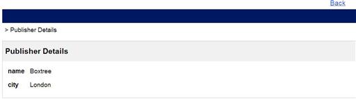
FIGURE 12.70 Rendering for the publisher retrieve page.
Figure 12.71 presents the publisher update page, which is accessed by pressing the update link on the main page list. This page is identical to the page for creating a new publisher except for the fact that it preloads data instead of being blank, and that as the name attribute is immutable, the respective field is defined as not modifiable.
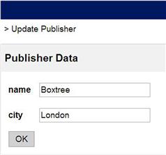
FIGURE 12.71 Rendering for the publisher update page.
12.10 Use case interface modeling with IFML
As seen in the previous section, working with basic operations at this level may rapidly make the diagram too complex to be read easily. One option to deal with this complexity is to separate the interface project into different areas and deal with one at a time. This is possible at this time because use cases have already been explored and the team has a deeper understanding about the system structure and user needs, which allows them to design an acceptable interface.
The design of the customer interface may start with the use case diagram of Figure 3.11, part of which is presented in Figure 12.72.
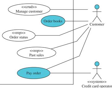
FIGURE 12.72 Partial use case diagram of Livir with the customer’s use cases.
Based on this use case diagram one possible interface design that could be prepared has three main areas:
• Shopping cart: orders and payment.
• My account: login and personal data.
• Reports.
This is still a very crude design, in the sense that no usability issues were raised in deciding on the best organization. However, it is effective. Figure 12.73 shows the IFML design of those areas.
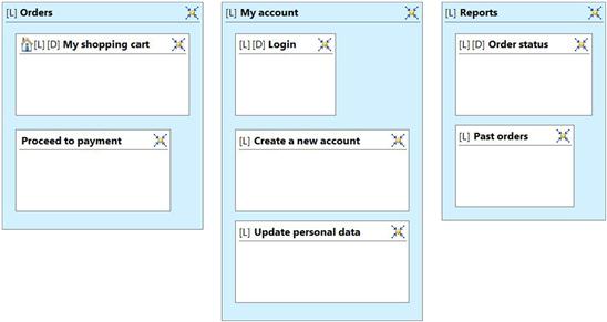
FIGURE 12.73 Initial high-level design for the customer site view of Livir.
Now let us take a look at the use case 01: Order books. Its system sequence diagram is depicted in Figure 12.74.
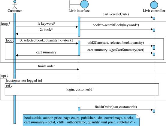
FIGURE 12.74 System sequence diagram for use case 01: Order books.
In order to prepare an interface design based on that sequence diagram, the team should look at the system operations, including their parameters and results:
• Any system operation, be it a command or query, must be activated somewhere in the interface. The activation can be obtained by clicking a button or a link, by selecting an item from a list, etc. Sometimes the same event may activate more than one system operation: if two or more system operations happen just after a system event (left side of the sequence diagram), then they are possibly activated by the same user action.
• Any parameter a system operation has must be obtained somewhere. Some parameters could be obtained from other sources (such as a clock, for example), but most parameters would be obtained in the interface. Thus, for most parameters there will be an interface view component (usually a form field) that allows the user to introduce the necessary data.
• Any result obtained by a system query must be presented somewhere. Some results may be hidden from the user in some cases, but usually they are presented. View components such as lists, details, and others may be used to show system query results.
In order to proceed with the interface design the recommendations above are followed and view components are created to hold all necessary parameters and results. System operation actions (shaped as hexagons) are added to the diagram as well. Figure 12.75 presents the evolution of the interface design for the My shopping cart page, which implements part of the use case 01: Order books.
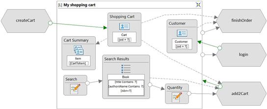
FIGURE 12.75 Further refinement of the interface design for the My shopping cart page.
The system operation createCart produces a new cart which is presented by the details Shopping Cart. The user can use the form Search to search for books, which are presented in list Search Results. There the user can select a book and define the desired quantity at the form Quantity. That activates the system operation add2Cart. That operation takes parameters from Shopping Cart (the cartId), Search Results (the isbn) and Quantity (the quantity). After a book is inserted in the cart it is automatically shown in the multiple details Cart Summary.
Before finishing the order, the customer should login if she has not yet done that. Finally, the order may be finished by performing the system operation finishOrder, which takes parameters from Customer (the customerId) and Shopping Cart (the cartId).
Thus, instead of using IFML operations for defining system operations, the team can use procedures defined externally as in Figure 12.75. In this case, the team may implement them in their favorite programming language.
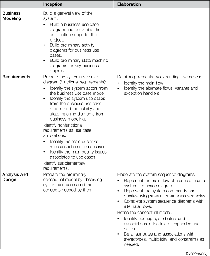
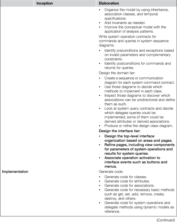
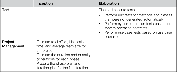
12.11 The process so far
12.12 Questions
1. Chose at least three use cases of the Livir system (Table 4.7): a CRUD, a report, and a nonstereotyped use case. Create a complete interface model for them.
2. Research some sources concerning the MVC (Model-View-Controller) and MVP (Mode-View-Presenter) design patterns. How many different definitions and variations for those models are you able to find? How do they differ from each other?
1IFML is currently an ongoing standards project, and the first draft was published in March 2013. It may be accessed at http://www.omg.org/spec/IFML/.
2Available at www.IFML.org/.
3The first IFML-compliant tool.
4www.w3.org/Style/XSL/
5And operations as explained later.
6Replacing a link.
All materials on the site are licensed Creative Commons Attribution-Sharealike 3.0 Unported CC BY-SA 3.0 & GNU Free Documentation License (GFDL)
If you are the copyright holder of any material contained on our site and intend to remove it, please contact our site administrator for approval.
© 2016-2026 All site design rights belong to S.Y.A.