Object-Oriented Analysis and Design for Information Systems: Modeling with UML, OCL, and IFML (2014)
CHAPTER 5
Expanded Use Cases
This chapter explains how to detail use cases as text and how to evolve them to system sequence diagrams in order to discover which high-level operations should be implemented by the system. It concentrates on explaining what is really necessary for a use case description during Elaboration, when its functionality must be completely understood. Technical and interface details are still avoided. Only information flows, including variant and exception flows, are included in an essential use case description; this chapter explains how to discover them systematically. It also explains how to transform a textual and informal description of a use case into a sequence diagram, which is a higher ceremony artifact.
Keywords
Detailed use case; expanded use case; full-dressed use case; exception in use case; use case alternate flow; essential use case; CRUD use case; system sequence diagram
Key Topics in this Chapter
• Main flow of an expanded use case
• Alternate flows: exception handlers and variants
• Writing recommendations
• System sequence diagrams
5.1 Introduction to expanded use cases
As explained in Chapter 3, use cases may be used to represent system requirements, among other things. They are nowadays one of the leading approaches for requirements because they allow the building of a structure that is easier to understand, communicate, and manage than previous approaches. Ivar Jacobson identifies some reasons why use cases became so popular:1
• A use case model is a picture that allows a team to describe even a complex system. It tells in simple terms what the system is going to do for its users.
• A use case produces value to a particular user, not to an unidentifiable community of them.
• Use cases are also test cases; when the team finishes organizing requirements in use cases they have also produced the structure needed for test cases.
• Use cases are the starting point to design effective user experiences, such as, for example, a website.
• Use cases drive development from analysis to design, from design to code, and from code to testing.
Frequently, the first analysis activity of Elaboration iterations is to detail the use cases assigned to the iteration. The process of detailing or expanding a use case into a sequence of steps corresponds to refining the requirements analysis, especially the functional requirements. In each iteration, it is possible to expand one or more use cases and analyze and design the necessary structures for the software product to meet the requirements, allowing users to interact with the system by following the steps indicated in the expanded use case.
In order to proceed with the expansion of a given high-level use case, it is necessary to have at hand the system use case diagram, including all annotations, and the supplementary specifications document. It would also be useful, for the first iteration, to have a version of the preliminary conceptual model if it was developed during Inception. For iterations other than the first Elaboration iteration it is very useful to have a version of the evolving conceptual model already refined by the activities of past iterations.
As use case expansion corresponds to the refinement of the requirements analysis, the team must conduct a very detailed exam on the process incorporated into the use case from the point of view of the user. The use case must be described step by step: how it is performed and which interactions between actors and system do exist. Technology and interfaces should be ignored at this point. Only the information exchanged between the system and the actors is mandatory in these descriptions.
This step-by-step description, in principle, must not be structured with branches. It must be based on a default sequence, or main flow (Section 5.2), which describes what happens when everything goes right during the use case interaction. This flow is also called the “happy path” because in it there are no error, failure, or exception.
After describing the main flow of the use case, the business rules or nonfunctional requirements annotated for the use case must be checked and analyzed from the point of view of the user, in order to discover what could possibly go wrong in a given step, which could generate an exception. After identifying a possible exception, a description of a procedure to correct the problem should be described (Section 5.3.3). There may be at least one exception for each business rule. The use case is then completed with alternate flows that resemble the handlers used for exception handling in programming.
Besides the above, the team can verify if the user may be able to execute the use case in a number of different ways or scenarios (Section 5.3.1). If its execution structure varies greatly, then variants to the main flow may be identified (Section 5.3.2).
5.2 Main flow
The main flow is the most important section of an expanded use case. It is the description of the use case process when everything goes right, that is, when no alternate flow occurs.
In the bookstore example, a first draft of the main flow of the Order books use case may include the customer identifying herself, searching and selecting books, and finally proceeding to payment.
Regarding user identification, a recurrent problem arises here: What if the user has already identified herself on a use case that was executed just before the current one? This is a common situation and must be adequately dealt with. As at this point user identification is optional, it may be left as an alternate flow, as explained in Section 5.3. Thus, it is assumed for the main flow of this use case that the user is already known by the system; if this is not the case, an alternate flow where the user identifies herself should be performed.
Therefore, the actions that better describe the main flow of use case Order books are the following: a user searches and selects books for buying and proceeds to payment. However, this is not a one-way communication, and the system must present to the user which books are available for sale, as well as other information that is important to the user such as the books’ prices, and the total value of the order.
Figure 5.1 presents a draft for the main flow of the Order books use case, which is considered the highest priority use case of the Livir system (Section 4.3.5).
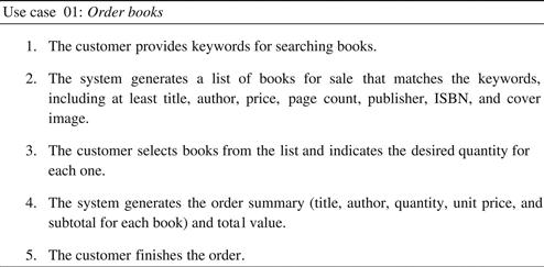
FIGURE 5.1 First draft for the main flow of the Order books use case.
At step 1 the user may choose not to provide a keyword, and then at step 2 she would receive a list with all the books available at the bookstore. For now it is not necessary to decide on the interface format. For example, if the list of books is too long, maybe a limited list with scrolling commands would be preferable to a complete list. This can be decided when the interface is being designed. The interaction of the user with the scrolling commands of the interface is something that should not be included in the essential use case description.
In order to execute step 5 it is necessary that the user is identified and validated, or else how would she resume the order later? The main flow here assumes that she is already identified, but if this is not the case, an exception would be raised as explained in Section 5.3.3.
After step 5 it is assumed that the use case finishes and the shopping cart has been saved (as it is an internal operation, it is not necessarily mentioned in the use case, as explained in Section 5.4.6). At this point, the user can chose to log off and resume shopping some other day, or she can proceed immediately to the Pay order use case (Figure 5.2).
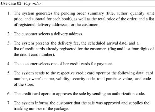
FIGURE 5.2 First draft of the main flow of the Pay order use case.
Note that these use cases are drafts because we still must discuss some issues and make some improvements in their formulations, which will occur in the upcoming sections. For example, the alternate flows that will be presented later are related to the possible exceptions and variants identified by the team. For example, step 3 of Order books may present an exception such as insufficient quantity of the book in stock. Another evident exception may happen in step 5 of Pay order, in which the credit card operator approves the sale: although this is expected for the success of the use case, it may not happen.
Exceptions, however, instead of producing conditional tests in the main flow, must be ignored by it, and handled separately. It would be harder to understand the purpose of a use case that has in its body an algorithmic structure that considers all possible exceptions, like the one shown in Figure 5.3.
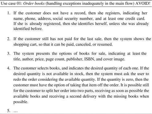
FIGURE 5.3 Use case with exceptions inadequately handled in the main flow.
The problem with the use case flow in Figure 5.3 that makes it so unnecessarily complex is the quantity of “if-then” statements in its formulation. The main flow should not be sprinkled with conditions. It should indicate what would happen in an ideal situation in which all information passed is correct and complete. Exceptions and other variations to the main flow should be handled as alternate flows, as seen in the following section.
5.3 Alternate flows
A use case specifies a process that can be performed in real life in a number of different ways. Two people buying books would take different sequences of steps. If the sequences are sufficiently similar,2 then the same flow must be used to describe both. But in some situations alternate flows must be used to indicate sequences that could occur in quite different ways.
There are basically two kinds of alternate flows: variants (Section 5.3.2), which indicate different ways to reach the same goal, and exception handlers (Section 5.3.3), which indicate how to deal with problems that appear during a use case execution.
However, sometimes the variants are so different that they can be considered individual use cases. Then, variants may be simple scenarios (Section 5.3.1) of a single use case, or, sometimes, they may be the key to discovering brand new use cases.
5.3.1 Scenarios
A use case can be understood as a description or general specification that supports a set of different scenarios. Each scenario is a particular realization or instance of the use case. Usually, a use case has a main scenario (execution of the main flow) and alternate scenarios (executions of the main flow that pass by one or more alternate flows). However, the notion of main flow variants sometimes creates doubt on what should really be a use case. In the bookstore example, considering the process for buying books, at least two different scenarios come to mind:
• A customer orders books and saves the shopping cart to continue shopping later.
• A customer orders books and pays for them.
Is it a single use case with two alternative ends? Or should it be split into two use cases?
Both options are equally valid, although one of them is possibly more useful than the other. The choices are:
• Create more use cases (one for each scenario). Each use case has a simpler structure, but there would be a high number of similar use cases.
• Group similar scenarios in a single use case. There are a smaller number of use cases, but each of them would be more complex.
At this point, it is more important to discover the information exchanged between the actors and the system than to decide if two scenarios consist of one or two use cases. Thus, it is not so important, with regard to the final result, if the operations are discovered or described in a single use case with two scenarios or in two use cases each with a single scenario.
The advantage of joining alternate scenarios into a single use case is that the description of some steps must not be repeated in different use cases. This is the same advantage that is obtained when the attributes of different classes are shared by a superclass (Section 6.6.1).
However, use cases must not be considered similar to procedure calls: they are linear descriptions of scenarios that may happen in the real world where a user is interacting with a system.
5.3.2 Variants
It is admitted, in principle, that the main flow is a strict sequence of interaction steps: it is neither branched nor nested. However, sometimes it could be useful to represent the main sequence in a not-so-linear way.
As mentioned in the previous section, use cases for ordering books and paying for them could be considered a single use case with two scenarios. In that case, each scenario would be an alternate end for the use case: Save shopping cart or Proceed to checkout.
These two possible endings may be represented as variants of the main flow of a single use case.
As shown in Figure 5.4, the use case Buy books has two possible ends: in the first, the cart is saved so that the order can be resumed later, and in the second, the customer pays for and finishes the order.
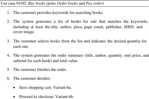
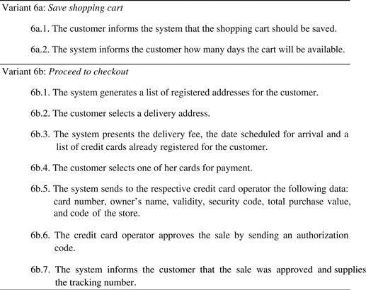
FIGURE 5.4 Main flow of a use case with variants.
Saving the cart to resume the order later is not an exception (in the sense given in Section 5.3.3) but an option for the customer. That is not a condition that prevents the use case from concluding, because the use case still produces something: the cart is stored to be used later. This is just a main flow variant, and this is why both variants are shown with the same status in the flow.3
Some analysts might choose one of the variants to be in the main flow and the other to be an alternative flow in the form of a variant. In Figure 5.5 the variant Proceed to checkout was chosen to be in the main flow, while the variant Save shopping cart was left out of the main flow. An advantage of this choice is that it allows the variant to be associated to more than one step in the main flow. For example, consider that the variant Save shopping cart may be executed when the user is in any step from 1 to 8. In this case the variant code would be numbered 1-8a. If the variant could be executed at any time during the main flow, then its number would be *a.
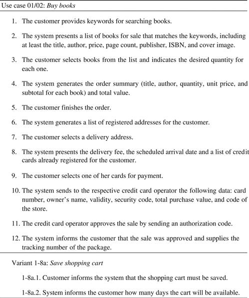
FIGURE 5.5 Alternative way to represent a use case with variants where one is kept in main flow and the others are alternate flow.
This style, although predominant in literature, forces the use case analyst to make a choice between variants that may be artificial in some cases. If there is not a clear predominance among the different variants, then a style such as the one presented in Figure 5.4 seems preferable, because it gives the same status to each variant.
5.3.3 Exception handling
After describing the main flow of a use case and adding variants (if any), the analyst must concentrate on identifying the exceptions that could occur and create an alternate flow for each one. There are basically two techniques for identifying exceptions:
1. Each business rule annotated for a use case may generate an exception. For example, if the use case for ordering books has a business rule that states that the value of the order cannot be lower than 50 dollars, then when an order is confirmed there will be an exception if it does not reach that value. To deal with this exception it will be necessary to add more books to the order, or it will be canceled.
2. Additionally, the analyst may look at each of the steps of the main flow, especially those that represent information flowing from actors to the system. In those flows there will be possibly data that the system cannot accept by definition, which constitutes an exception. For example, in the step where the credit card operator is asked to authorize the sale it could send a refusal code – this would be an exception, because the use case cannot be successfully completed in that case. Corrective actions must be taken (outside the main flow), or the use case will be terminated without achieving its goals.
An exception (in the sense used in computer science) is not necessarily an event that seldom occurs, but an event that if not handled prevents a process from proceeding. An exception is not necessarily something that prevents a use case from starting, but it is normally something that prevents it from being concluded. The fact that the credit card has reached its limit does not prevent the customer from accessing the bookstore site and starting to shop, but it prevents her from completing the order unless a valid credit card with available credit is provided. Therefore, although the use case may be initiated, it cannot be concluded until every exception that occurs is handled.
Figure 5.6 shows an evolution of the use case Order books, now with some exceptions identified after the main flow. Each exception is identified by a number that indicates the line of the main flow where it originates, and a letter that helps differentiate exceptions that may happen in the same step. For example, if step 5 has three exceptions, then they will be identified as 5a, 5b, and 5c. If an exception can occur in any step, then it is identified as *a, *b, etc., and if it can occur in a range of steps, such as 3-7, than it is identified as 3-7a, 3-7b, etc. Additionally, if an exception can occur in nonadjacent steps, such as steps 3 and 6, than it may be identified as 3,6a. A sentence follow the identification code that corresponds to the business rule or situation that is the cause of the exception. Figure 5.6 also introduces variant 5d that allows the user to continue shopping for other books instead of finishing the order. This is not an exception, just a choice.
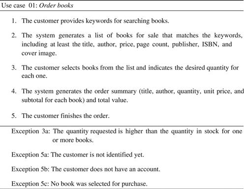
FIGURE 5.6 Example of use case with exceptions identified.
The number of exceptions a team may come up with may be very high; however, we are interested in just a few of them. Most exceptions that could be thought of may be resolved by other mechanisms than the logic of the use case. A key for reducing the use case complexity and still dealing with the system complexity is to reduce the number of exceptions identified here to those that really must be addressed. The exceptions that are really interesting now are the ones where the user tries to send the system some data that cannot be accepted. Any other kind of exception probably can be resolved by other mechanisms. In the example of Figure 5.6:
• In step 1 there can be no exceptions because the system may accept any keyword that the user provides. It just happens that for some choice of keywords there may not be any book to present. In this case, the behavior of the system should show no books, or maybe show the books that most closely meet the keywords (Google does that). This is not an exception that prevents the use case from continuing, just a special case of its behavior.
• In step 2, and any other step where the system is presenting data, there can be no exceptions in logic, because in step 2 the system is not trying to accommodate data sent by the user; if some exception could occur, then it probably would have happened in the previous step and generated an effect here. The system showing a list with no books is not an exception. Again it is a special case of its normal behavior, and the user action would be choosing no book in step 3 and after that repeating step 1 or proceeding to finish the order in step 5.
• Still in step 2, an analyst could think “What if the calculations involved with the query have a defect that makes the system halt when trying to present the result?” Well, if the code has a defect, then it must be corrected, and not incorporated in the use case logic. This is not the kind of exception we are interested in.
• At any step, an analyst could think that an exception could happen if the communication between the system and the user fails. That is what developers usually understand as a real world exception. However, this is not the kind of exception we are interested in here, because it is not specific to the logic of the use case; communication may fail at any time – it does not matter which step of which use case is being executed. Additionally, this exception is related to technology, and we are dealing with essential use cases, where references to implementation technology are avoided. Thus, this kind of exception must be implemented by general mechanisms, not by the logic of the use case.
• In step 3, what if the user indicates a negative quantity? What if she writes a letter in the quantity field? Here the idea is that all bad user actions could be eliminated by simple interface widgets. For example, instead of writing a number in a text box, the user selects a quantity by sliding a bar that represents only positive quantities. These interface mechanisms are part of technology and they are not to be mentioned in the essential use case. However, the analyst may know that there are ways to prevent a user from choosing a negative or a “xyz” quantity, and therefore this is not a preoccupation that must be included in the use case structure. As explained in Chapter 8, this kind of syntactic user error will be addressed by defining the type of arguments that the system can receive. If the type is defined as “natural,4” then the team must not be concerned with any other values; they simply cannot be produced by the user. The interface will not allow it.
• However, there is a logical exception in step 3, which corresponds to the user asking for a quantity that is more than is available in stock. The quantity of books available in stock varies from book to book and varies in time. Thus it cannot be defined as a static type. The system could prevent the user from choosing a quantity that is higher than available, but in that case, the system would have to check for those quantities prior to the user action.
• Finally, step 5 has at least three exceptions that are just the type we are looking for; three problems that are related to the use case logic and that prevent the use case from achieving its goals: a user that is not identified yet, a user that has no valid identification, and an order with no books selected.
Through the discussion above we can conclude that in practice exceptions happen usually in steps that correspond to information being sent to the system, because only in those cases are there business rules or situations that prevent the system from accepting the data and proceeding further. Lots of potential exceptions may be treated as type check or technological issues, as explained above. And in most cases, exceptions identified in a step where the system is presenting information should have been dealt with at the previous step where the user was sending information to the system. In summary, interesting exceptions in a use case flow are those in which the user tries to send information that the system cannot accept.
Each exception must be handled by an alternate flow that corresponds to a branch of the main flow. This alternate flow defines a sequence of steps that should be performed to eliminate the problem created by the exception. If this sequence of steps cannot be performed or if the actor does not want to perform them, the only option left is to abort the use case, that is, terminate it without reaching any of its goals.
Therefore, each exception identified in a use case has an exception handler. An exception handler has at least four parts:
• An identification code that, as explained above, consists of the number of the step(s) that originates the exception followed by a letter that identifies the exception.
• The exception, which consists of a sentence that states which business rule was broken, because in a single line in the main flow different kinds of exceptions may happen, as in, for example, step 5 of the use case of Figure 5.6.
• Corrective actions that consist of an alternate flow, that is, a sequence of actions that should be performed to correct the exception. The corrective actions are numbered sequentially and each step is prefixed by the exception identification. For example, exception 2a has steps numbered as 2a.1, 2a.2, 2a.3, etc.
• Finalization, which is the last line of the alternate flow and indicates if and how the use case returns to the main flow after performing the corrective actions.
There are five basic ways to terminate a corrective actions sequence:
1. Terminate the use case normally after the corrective actions are performed. By default, if no finalization action is mentioned, it is assumed that the use case terminates at the end of the alternate flow. The use case does not return to the main flow but its goals are reached by the alternate flow.
2. Go back to a step before the one that caused the exception. Sometimes it is necessary to go back to the beginning of the use case or move back some steps before the one that caused the exception. This is neither very common nor desirable, because it implies that the user will repeat steps that have already been taken. However in systems that must obtain data in real time or systems with intensive concurrent transactions this may be the case.
3. Return to the step that caused the exception and perform it again. This is more usual. One must choose this option when the step that caused the exception could eventually cause other exceptions even if one of them has been already handled. This is the case for the exceptions of step 6 in Figure 5.6, because in addition to not having a valid identification the user could not have selected any books.
4. Advance to some step after the one that caused the exception. This can be done when corrective actions have already produced what the step or sequence of steps were supposed to do. However, it is still necessary to check if new exceptions could happen in the main or alternate flow (see the previous option).
5. Abort the use case. In this case, the control does not return to the main flow and the use case does not reach its goals. If it is necessary to perform some corrective actions (for example, removing transient records) this may be indicated in the steps of the alternate flow (this approach for handling an exception is known as organized panic).
Figure 5.7 presents a new version of the Order books use case, now with the corrective actions for the alternate flows defined.
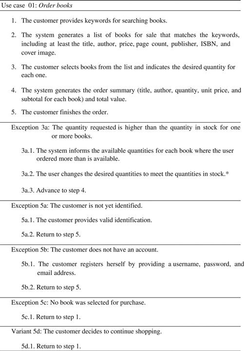
FIGURE 5.7 Example of use case with exception handlers. *Contrary to what was stated in chapter 2, here we assume for simplicity that books out of stock cannot be sold.
In the example, each exception identified and handled is specific for the step where it occurs. For example, the quantity of books available may only be detected in step 3 when the user provides it.
It is important that only exceptions that are specific to some steps are effectively included in the use case. Otherwise, it could quickly become unnecessarily complex. Generic exceptions that may occur at any step of any use case must not be treated as exceptions here. For example, the actor may cancel a process at any step. That kind of situation is more adequately handled by generic mechanisms. For this example, a generic mechanism of rollback should be provided for the system. If this kind of exception was included in every use case, then a huge number of similar exceptions would be introduced with no practical result. If at any step of any use case the user can cancel the transaction, it is not necessary to repeat that information many times. There could exist hundreds or thousands of steps in the set of use cases of a system. Generic exceptions that are specific to a single use case may be numbered with the “*” notation. Otherwise, if the exception may happen in any use case or in a great number of them, then it must be recorded in the supplementary specifications document, and therefore must be implemented by general mechanisms, not by specific use case steps.
5.4 Writing recommendations
The writing style of a use case should follow a pattern like “actor provides… / system informs….” Styles like “system asks…” should be avoided because what must be represented in the use case is the flow of information, not the occasional demands that gave rise to those flows; those demands do not exist in every scenario, and in most of them they are not even necessary.
The team must avoid placing tests in the use case main flow. Tests like “if the user has a record then the system presents…” should be avoided. That kind of test is unnecessary because exception handlers should already be associated to the steps of the main flow. Then, if an exception occurs, it would be handled in an alternate flow.
These tests must not be placed in the main flow to keep it from becoming a complex flowchart instead of a straight, simple sequence of steps. Lots of “if/then” statements can make the flow obscure, and the stakeholder would not know what the expected flow (happy path) is.
The only situation in which a test would be acceptable in a flow is when it is about an optional single step, as, for example, “if the user wants, she may also provide her cell phone number.” But even in that case, an alternate flow would be a better choice.
Another common writing concern is that a use case must alternate inputs and outputs of information. In other words, normally a use case has the form “actor provides … , system informs … , actor provides … , system informs … .”
Sequences such as “actor provides … , actor provides … , actor provides …” or “system informs … , system informs … , system informs …” must be avoided unless justified.
The idea behind the alternating pattern is to reduce any discrepancy on the number of steps that different analysts could assign to the same use case. Without that rule one analyst could write:
1. The customer provides her name, ID,5 and phone number.
On the other hand, another analyst could write:
1. The customer provides her name.
2. The customer provides her ID.
3. The customer provides her phone number.
The most useful and correct version under this point of view is the first, because, among other things, the second would demand that the information be provided in the order of the steps: after providing her ID, the user cannot go back and correct her name. Thus, the first version is more compatible with most information systems, which present interfaces where information may be entered and edited before it is finally sent to the system.
A sequence of two input steps can be justified only if the first step may cause an exception that can prevent the use case from proceeding further. One example of this is:
1. The customer provides identification.
2. The customer provides the flag, number, expiration date, and security code of her credit card.
In this example, when the customer presents identification, an exception would occur if the identification is invalid. In that case, the information about the credit card must not be given by the user. The actor will only give that information after the first step is performed or corrective actions were taken.
Even in that case, an intermediary validation step could be used to improve the understandability of the sequence, such as:
1. The customer provides identification.
2. The system validates customer identification.
3. The customer provides the flag, number, expiration date, and security code of her credit card.
Finally, some system messages may be avoided in the use case flow because they do not involve the system presenting stored information. For example, the first step for the alternate flow for exception 5a in Figure 5.5 could be “The system informs the user that the customer was not yet identified.” That is not an error, but the step is somewhat redundant in the flow because the exception already states the condition that causes it. When designing an interface for handling that exception the team should be concerned about error messages like that. However, it is not necessary for understanding the flow of information of the use case. Consider that if it was necessary then any exception handler in any use case should start by presenting an exception message, this can already be inferred by the exception condition. It can be assumed by default that the message will be shown, and thus mentioning it every time is not necessary.
5.4.1 Essential versus real use case
A frequent doubt about use cases is what system must be described? The current one? Or the one that will be built? If the current operations are performed manually, and in the future they will be performed with a computer, what must be the description provided by the use case? The answer is none, but both! The use case written for analysis purposes must describe the essence of the operations, not their concrete realization. Thus, the analyst should always try to avoid mentioning the technology used to perform the process and concentrate only on the exchanged information. Instead of writing “the clerk writes the customer name and address on a paper sheet,” corresponding to a manual technology used normally in nonautomated systems, or “the customer fills in the name and address on the main screen,” which corresponds to an automated technology, the analyst must register the use case simply as “the customer provides a name and address.” The last form is technology-free and interface-independent and represents, therefore, an essential description for the operation.
All use cases used for requirements purposes should be, in principle, essential. Essential in this context means that the use case is described in a language where only the essence of the operations is presented, not its concrete counterpart. In other words, the analyst must describe “what” happens between the user and the system without informing “how” that interaction happens. The analyst should not, therefore, while doing analysis, try to describe the interface technology between the user and system. This will be described during design time in which real use cases could be written after the real interface has been designed. Real use cases stay attached to a specific interface technology, while essential use cases are technology-free.
Why essential use cases? According to Ambler (2004), real use cases (those that mention technology) contain too many built-in assumptions, often hidden or implicit about the underlying technology of interface implementation strategies. That may be a good feature during design, but not during requirements analysis. An essential use case, on the other hand, states the user needs or intentions, and not the concrete technology that could support those needs.
As the description of the use case at that moment is made without reference to the interface technology, it is not necessary to decide what the interfaces look like, but only what information is exchanged between actors and system. References to menus, windows, buttons, and other graphical devices must be avoided in the text of the essential use cases.
So how do we describe use cases that seem to be particularly concrete such as, for example, drawing money from an automatic teller machine? How do we do that without describing technology? It is possible. Instead of saying “the user passes a magnetic card” one could say that “the user provides identification.” Instead of saying that the machine “prints the account details” one could say that the machine “presents the account details.” Thus, by eliminating the reference to the physical technology, only the essence remains. This opens the way for the design of innovative technologies later, that is, interfaces different than those that can be seen at a first glance. For example, the user could be identified by fingerprints, the receipt could be sent by SMS (Short Message Service), and even the money could be delivered in cash or in credits to a preloaded card.
It is the responsibility of the analyst to study the current processes of the company and produce an essential version of them in the form of use cases. Later, the designer will give a new form to those processes by using technology to produce a new concrete version of the system.
5.4.2 Explicit information
For the sake of understanding use cases as functional requirements, it is recommended that the analyst make explicit the individual data pieces exchanged between actors and the system. Thus, instead of a laconic “the customer provides her data,” the use case should say “the customer provides her name, ID, email, phone, and address.”
Eventually, a term such as “customer” could be externally defined as meaning “name, ID, email, phone and address.” An expression such as customer=<name, id, email, phone, address> could be written. If that definition is adequately registered, for example, in the conceptual model, or in a data dictionary, then it can be used in the use case text to avoid repeating the individual elements every time they are needed.
5.4.3 Identification and selection
A recurrent problem associated to use cases is how to identify people and things. For example, a customer must be identified and validated in order to conclude the Order books use case. How does she do it? Username and password? Social security number? Fingerprints? Selecting the name from a predefined list or menu? To keep the use case essential, that particular action must be left generic, and references to possible ways for identifying a customer must be left to design. Furthermore, the computer security community already has established common methods to securely validate an identity, and these proven methods should be used instead of reinventing the wheel. For now, the use case will simply state that the user provides identification, without mentioning by which means that identification was obtained and validated. This can be done when security issues are designed into the system.
Another example is the selection of books for purchase. Does the customer submit the ISBN of the book? Select it from a list? Use a natural language speech interface? During use case expansion these issues do not need to be decided (unless they are indeed nonfunctional or supplementary requirements). At the essential level of the use case the user simply selects books. Later, the design will present some options to provide the means for the user to make that selection in the most comfortable way.
5.4.4 Mandatory steps
One of the biggest doubts reported by teams that work with use cases is about what steps to include in the expanded use case.
In fact, two people that describe the same use case, unless they have a nicely established convention, may produce different step sequences. For example, in a traditional bookstore, one analyst could state that the clerk asks the customer which books she wants; but another analyst could ignore that step and state that the customer simply picks up the books and give them to the clerk for purchase. The question is: Which one of the two versions is right?
Both may be correct, but one of them is more useful. In any scenario of that use case, it is mandatory that the customer selects the books she intends to buy; otherwise the order cannot be completed. However, it is optional for the clerk to ask for the books. That may happen just in some scenarios, but not in all of them. Thus, selecting books to buy is mandatory, but asking for that information is optional in the flow of the use case.
Analysts must be encouraged to build correct versions of the use cases, but we should not stop there: different analysts should build similar descriptions for the same process. This can be obtained when the number of optional steps is minimized.
Every use case has mandatory steps. These steps include information that is passed from the actors to the system and from the system to the actors (Figure 5.8). Without one of those steps, the use case may not make sense. Those steps must appear in any expanded use case, and their absence implies that the use case is incorrect.
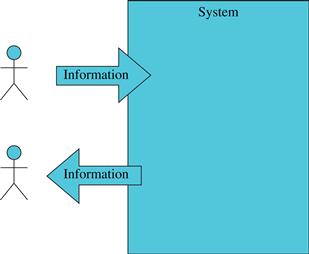
FIGURE 5.8 Mandatory use case steps.
Other steps such as “ask for books” are optional or complementary. They may help contextualize the use case, but they are not fundamental because they do not transmit any information through the system boundary.
Thus, an expanded use case for buying books must contain steps that indicate that the customer selects books to be bought. The customer should also inform the system how many copies she wants if this is the case. The system must inform the customer of the total value of the purchase. Why are these steps mandatory? Because without exchanging this information it would be impossible to adequately register a sale. Certainly it would not be of great help if a system registers a sale without mentioning which books were sold or how much was spent. Because that information is so important for the conclusion of the use case it is considered mandatory for the expanded use case.
In a use case description the information does not appear from nowhere. It is transmitted from the actors to the system and vice versa. The absence of any mandatory step may make the use case seem incomplete, as shown in Figure 5.9, where a use case was poorly described because mandatory information was omitted.
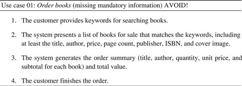
FIGURE 5.9 An example of a poorly described use case that is missing a mandatory step.
The use case in Figure 5.9 is incomplete because an order would need more information than the use case description provides. How could the system know which books the customer wants to buy? No matter how the information is obtained, it is mandatory data that must be received by the system, and therefore it must be registered in the use case.
There is a clear reason for making all mandatory information appear in the expanded use case: this information will be used later to define what the system operations are, that is, what methods have to be implemented in order to satisfy the requirements. If this information is not complete at this point, incomplete methods would be implemented later, and that will raise a need to redo part of the system when the problem is identified.
Furthermore, the information contained in the mandatory steps of the use cases will be used to refine the conceptual model, which is the basis for the structure of the classes of the system.
Depending on the direction the information goes, mandatory steps may be identified as:
• System events: Steps that indicate that some information is transmitted from the actors to the system.
• System returns: Steps that indicate that some information is transmitted from the system to the actors.
Special care must be taken when considering system returns. For those steps to be really mandatory they must pass some information that the system stores or can access. That information must be something that in principle the actors do not have access to except by querying the system.
For example, the system must inform the actor of the total value of the purchase in the use case Order books. Otherwise, the actor will not know how much to pay. That information could, maybe, be calculated by the customer if she mentally adds the individual prices of the books, but even so she could not be sure about the total value because information about discounts, taxes, and fees must be provided by the system. The responsibility for providing that information belongs to the system.
On the other hand, when a customer sends some information to the system, the interface may provide some kind of feedback to make clear the data were received and adequately processed. However, that feedback (normally a message such as “OK”, or “done”) is not a system return because it is not stored or derived information about books, customers, and orders. This kind of message is just an interface feedback, and therefore it belongs to the interface technology domain. As it does not consist of stored information it must not be considered as a mandatory step.
It may be interesting if system events and returns are explicitly identified in use cases. A reader that is new to use cases may choose to clearly identify mandatory steps by marking inputs with [IN] and outputs with [OUT]. Those markers may be placed just after the line number, as shown in Figure 5.10.
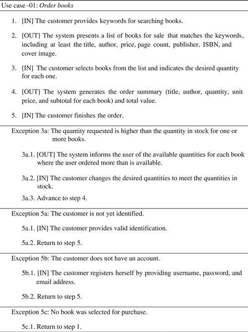
FIGURE 5.10 A use case with mandatory steps marked.
Those marks can also help the analyst to verify if each step is really a single transaction because no step can be marked with [IN] and [OUT] at the same time. It also helps the analyst to see if there are sequences of [IN] or sequences of [OUT] that could be joined into a single step.
5.4.5 Complementary steps
Another kind of use case step is the optional or complementary step, which does not represent an information flow between actors and the system. However, this kind of step can be used sometimes to help understand the use case context.
This kind of step usually corresponds to communication between actors (communication that does not involve the system, as shown in Figure 5.11) or to the description of actions or attitudes that also does not configure information flow, such as “the customer opens the bookstore home page,” “the customer decides to buy books,” “the system asks the customer for identification,” or “the clerk asks the customer which books she wants to buy.”
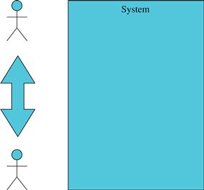
FIGURE 5.11 Complementary use case steps.
Complementary steps are not fundamental in essential use cases because they do not correspond to system events or system returns, as they do not transmit information through the system boundary.
Some of them can be even mapped to navigation operations during interface design. For example, a real use case (design) could have a step like “the customer selects an option.” That line does not correspond to a system event because at that time the customer does not pass any information to the system (such as name, phone, address, book title, etc.). That action corresponds simply to a change of state that will be implemented as interface navigation (a new screen is opened after the option is selected, for example).
5.4.6 Unsuitable steps
The team must keep in mind that, as the use case is a description of the interaction between actors and system, they must avoid including any internal system processes (Figure 5.12), such as “the system stores the information into the database.”. Those steps are considered unsuitable for the use case description.
FIGURE 5.12 Unsuitable use case steps.
The use case is a tool for describing the interaction between users and a system, not a tool to describe internal processing. The internal processes of the system will be better described during design with more adequate tools, such as communication diagrams.
In the use case description, the analyst must concentrate on describing the information that is passed from users to the system (for example, “the user selects the books to be ordered”) and from the system to users (for example, “the system presents the total”). Any aspect about internal processing must be omitted. It can be said that the system presents the total value, but not the steps taken by the system to calculate that value. In other words, the system still must be seen as a black box at this time.
If the analyst wants to record a formula or algorithm to perform a given calculation that is needed to present some data, then it can be done in the use case annotations and recorded as a nonfunctional requirement.
Figure 5.13 presents a situation where the description of a use case goes beyond the recommended, and unsuitable steps are added. The unsuitable steps are marked with [X].
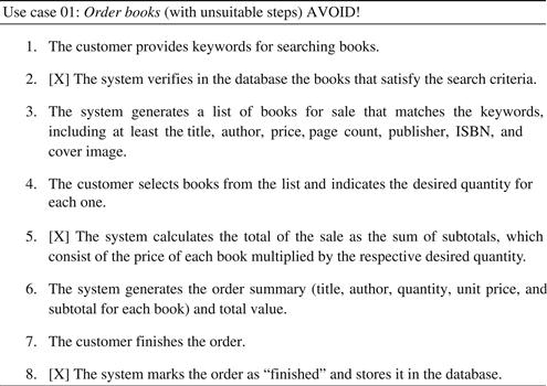
FIGURE 5.13 Example of a use case with unsuitable steps.
The use case in Figure 5.13 includes all mandatory steps but also includes unsuitable ones (steps 2, 5, and 8), which correspond to internal processing, not information input or output.
The fact that the system performs verifications, calculations, and internal queries does not affect its interaction with the user. The user only needs to know that the information she sends is received by the system, and it may be recovered from the system when necessary. How the system is going to do that is an internal problem that will be answered only during design and coding.
5.5 Included use cases and fragments
It is possible for two or more use cases to have coincident parts. For example, many use cases may include a payment fragment. In other cases a use case may include not only a fragment, but a complete use case. The include relationship can be used only when the duplicated fragment or use case is significant, that is, it should not be used when just one step is duplicated. An included use case or fragment may be called in a flow by using the “include” expression. Suppose that payment is a fragment that appears in more than one use case in the system. This fragment could then be called by any use case as done in Figure 5.14.
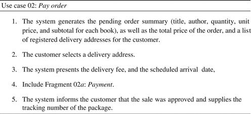
FIGURE 5.14 A use case that calls an included fragment.
The fragment itself can be defined as in Figure 5.15.
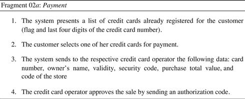
FIGURE 5.15 A use case fragment that may be included in more than one use case.
Notice that the fragment is not a complete use case in this example. It cannot be executed alone by a user; it only can be performed as part of another use case.
Some care must be taken here. First of all, use cases are not procedures like the ones used in programming languages; they are linear descriptions of real world processes. Analysts are not encouraged to structure use cases as they do with code. Included use cases or fragments may be used only when the situation really justifies it.
However, the analyst must keep in mind that the goal of the expanded use case in analysis is to help in understanding the nature of the interactions between the system and its actors, and not to structure a computer program to simulate that interaction. Thus the included use case or fragment calls must be used carefully.
5.6 Expansion of stereotyped use cases
Stereotyped or pattern use cases present medium or low risk to the software development process because the structure of their flows is already known. The indication of <<crud>> or <<report>> stereotypes, if adequately documented, may pass to the programmers a clear idea of what has to be implemented.
Ideally, if functional requirements are sufficiently detailed, stereotyped use cases would not need to be detailed. For example, if the specification of a report already presents all information it receives and returns, there is no need to write a detailed use case for it, because it would just repeat information that the analyst already has.
One concern that must be kept in mind during requirements elicitation is whether a use case that was identified really belongs to a pattern. Some analysis effort must be spent on the use cases before deciding if they really belong to the pattern.6 For example, reports must never change data. If the use case is presenting data but also changes data then it must not be defined as a report use case. It could be a variation of that pattern or a completely new structure that does not belong to any known pattern.
In the case of CRUDs what can be said is that not every entity of the conceptual model is suitable to be managed by the CRUD pattern. CRUDs are expected to be the simplest entities. If they get more complex, a set of non-CRUD use cases is necessary for describing how the user works with them.
For instance, an address or a credit card are very simple entities and could be nicely managed by a CRUD use case. On the opposite side, an order is one of the more complex entities of the bookstore system. Orders may be issued, canceled, completed, sent, resent, received back, etc. That does not characterize it as a CRUD.
In the middle of the scale there are concepts which the team must look at to decide if they may be adequately managed as a CRUD or not. For example, is managing customers a CRUD or not? Some time may be spent on analysis before the team can decide on that. Section 5.6.2 shows that it may be considered a variation of the CRUD pattern.
The expansion models for pattern use cases presented in the following subsections serve as a reference to the reader. They are presented in a form of a template, so that analysts can use them to write their own versions of pattern use cases, or even work on new patterns or subpatterns.
5.6.1 Report expanded
A report is a simple use case that consists of a single access and calculations on data managed by a system. The information sent by the actor consists of arguments for selection, filtering, ordering, grouping, etc. Figure 5.16 presents a general format for an expanded report use case.
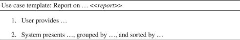
FIGURE 5.16 A template for the expanded report use case.
Figure 5.17 presents a concrete example of a report, that is, an instantiation for the template, applied to the Livir example.
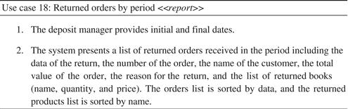
FIGURE 5.17 An example of an expanded report.
For the reasons explained in Section 5.3.3, this kind of use case does not have alternate flows (otherwise it would not be a report, but a different kind of use case). The user simply sends the arguments and receives a set of organized data in return. If the user passes the wrong arguments (for example, incorrect data), she will receive the right answer for the wrong data. For example, if the user passes by mistake a period in which there were no devolutions, then she will receive an empty list, which corresponds to the right answer for the arguments passed. In that sense, therefore, this kind of use case cannot have exceptions.
However, the team still must assure that the use case is really a report before sending it to design and coding, because it could be a variation of that pattern.
5.6.2 CRUD expanded
Just like reports, CRUDs are also use cases that follow a known pattern. This kind of use case consists of the optional execution of one out of four possible operations: create, retrieve, update, and delete.
This kind of use case has a main flow with four variants, because none of the operations can be considered a “happy path” or “exception.” They are distinct operations grouped more by convenience, for being associated to the same entity, than by similarities among their steps. Therefore, the main flow is just a user decision on which operation will be executed. Figure 5.18 presents a possible template for this kind of use case.
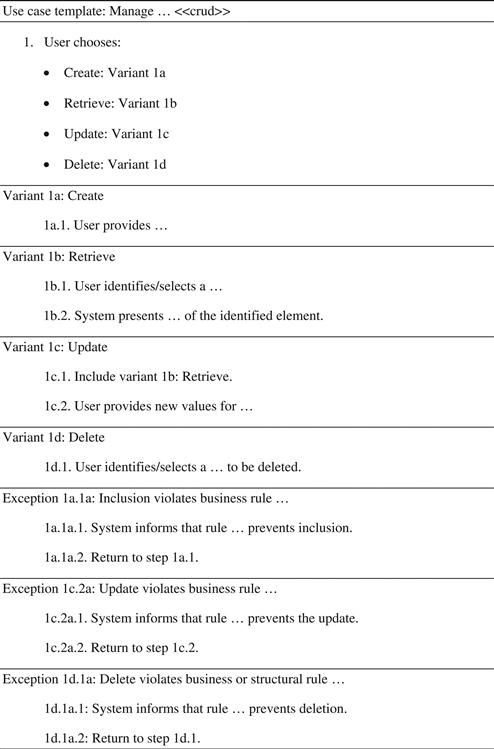
FIGURE 5.18 A template for an expanded CRUD use case.
Observe that in that use case template variant 1c (Update) includes the steps of variant 1b (Retrieve).
Exception handler 1d.1a uses a specific strategy that consists of preventing the user from deleting an object when there is some rule against it. In Section 8.5.4, this issue is revisited and other strategies to deal with this exception are discussed.
Figure 5.19 presents an example of expansion of a typical CRUD use case.
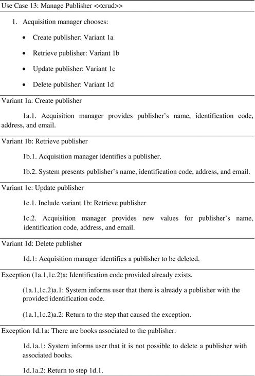
FIGURE 5.19 An example of an expanded CRUD use case.
In this example, two business rules were used to identify exceptions:
• The identification code for publishers must be unique, which must be verified both when a new instance is included and when an instance is updated. This produces exceptions in step 1a.1 and 1c.2, which may be identified as a single exception (1a.1,1c.2)a.
• If the publisher already has a book associated to it (and that association is mandatory for books, i.e., every book must be linked to a publisher) then it cannot be deleted. This is a structural rule that must appear explicitly in the conceptual model as a mandatory role from book to publisher (Section 6.4.1).
Figure 5.20 presents the CRUD use case Manage customers, which is a variation on the pattern. A customer can retrieve and modify only her own data. Thus, the use case must be adapted to that fact. On the other hand, it may be desirable that a system manager could access data from any customer. For that manager the use case would be a regular CRUD. Would two use cases be created here? One for the customer to manage her own data and the other for the system manager to manage data from all users? Maybe… but it seems that this approach would be quite repetitive. To make things even worse, imagine that it is possible for a regional manager to access the data of users only from her region. Would this be a third use case? This does not sound like a good solution.
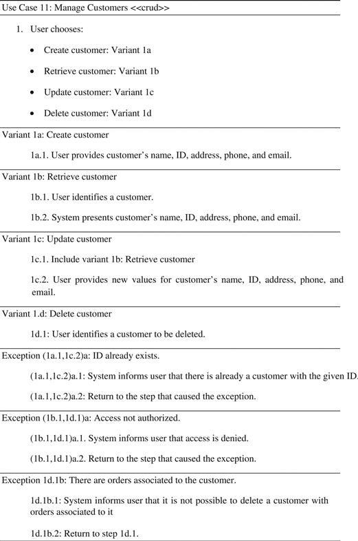
FIGURE 5.20 An expanded CRUD use case with access restrictions.
To solve this issue in an elegant way, the use case could be parameterized, indicating that the user can only access data from customers she is authorized to review. When customers are being managed, what must be verified by a given business rule is whether the user really has permission to access or change the data from the customer she is trying to access or change. In Figure 5.20 checking that permission is performed by exception handler (1b.1,1d.1)a: Access not authorized.
Notice that the use case in Figure 5.20 is a CRUD variation that could be called CRUD with access restriction, because the access to data depends on who is the user.
Other CRUD variations exist, such as:
• CRUDL: Including a variant to list the existing elements. Thus, instead of simply identifying an object to retrieve, update, or delete, the user can select it from a list.
• SCRUD: Including a variant to search elements.
• RUD: Where elements may be retrieved, updated, and deleted, but not created.
• CRU: Where elements may be created, retrieved, and updated, but not deleted.
Many other variations may be invented depending on the need and the cost/benefit of having more patterns to remember.
There is a simpler way to define a pattern-based use case if it fits perfectly on the pattern. This consists of simply listing the field to be filled and the business rules to be observed. For the rest, the pattern is applied. Figure 5.21 shows an example.
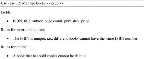
FIGURE 5.21 Example of brief expansion for a CRUD use case.
With the information given in Figure 5.21 and the template of Figure 5.18 it is possible to implement the use case without expanding it.
5.7 Other sections of an expanded use case
Since the concept of a use case was created (Jacobson, Christenson, Jonsson, & Övergaard, 1992), different formats have been proposed. Each proposal includes different elements. The “main flow” and “alternate flows” sections are fundamental for any detailed use case description. However, other sections can be included if the analyst needs them. Some of the most popular are presented in the next subsections.
5.7.1 Stakeholders
There are often scenarios where groups other than actors are relevant to a use case. Other sectors of the company could have some interest in the use case. For example, in the use case Order books the only actor is the customer. But the results of that use case may interest the stock and accounts departments, because the results of a sale may affect both the quantity of books in stock as well as the quantity of money available or to be received. Thus, even if those departments are not participants in the use case, they can be listed as stakeholders.
The utility of the stakeholders list for a use case is that the use case must satisfy all stakeholders. Thus, the documentation will be useful to remind the analyst to seek information that needs to be stored, processed, or transmitted, so that those interests can be satisfied.
5.7.2 Preconditions
By definition, preconditions are facts considered true before a use case even starts. Preconditions must not be confused with exceptions: exceptions may be detected only after the use case has started. Exceptions are detected during a use case because most of the time it is not possible to verify if the conditions were true or not before the use case begins. For example, it is not possible to assure that the customer has enough credit to pay for the order before starting the Order books use case, because the value of the order cannot be known at that time; therefore this is an exception. However, it is possible to admit that only a book that was sold and delivered can be returned. Thus, the sale and delivery of the book is a precondition for its return.
As preconditions are accepted as true facts before the use case starts, they will not be checked during the use case. Although there can be other interpretations in literature, these kind of preconditions do not generate exceptions. If they are false it should be impossible to start the use case (otherwise they are exceptions, not preconditions).
5.7.3 Success post-conditions
Success post conditions establish the results of a use case, that is, what will be true after the use case is executed. For example, the Order books use case may have as a post-condition the following result: “the order was registered by the system.”
5.7.4 Open issues
Sometimes, without the presence of the client, the team cannot decide about some issue that may depend on company policies. For example, may the customer pay the order in installments? Are there special offers for customers that buy more than certain quantities?
If the client is not immediately available, these doubts must be recorded in the use case section “open issues” in order to be solved as soon as possible.
At the end of the analysis activities of one iteration it is expected that all open issues have been resolved and incorporated into the use case description.
5.8 System sequence diagrams
Among other uses, the text of the expanded use cases may be used as:
• A source of information to discover the concepts and attributes for refining the conceptual model (Section 6.8).
• A source of information to discover system operations, which consist of the methods that encapsulate the domain tier of the system from the interface (Chapter 8).
There are two kinds of system operations:
• System commands, which change data and must not return data.
• System queries, which return data and must not change data.
That follows the Command-Query Separation or CQS principle of software engineering (Meyer, 1988), which allows for better code reusability and maintainability. A query that changes data would be less cohesive than a query without collateral effect and a command without return.
System commands are methods that are activated by a system event, that is, as a reaction to a user action. System commands, by definition, implement a flow of information from the outside to the inside of the system. Therefore, system commands update the information that is managed by the system.
System queries are methods that correspond to the simple verification of information already stored. That information may be presented exactly as it exists or modified by logical and mathematical operations (such as sum, average, etc.). By definition, a system query may not be responsible for the insertion of new information into the system. It should also not be responsible for updating or removing information from the system: it can only read information.
The set of system operations correspond to the total functionality of a system, that is, the set of all functions that can be performed by a user with the system.
Use cases are excellent sources for discovering system operations. System commands are basically associated to steps in which the user sends some information to the system (those marked with [IN]). System queries are associated to use case steps in which the system sends information to actors (those marked with [OUT]).
5.8.1 Elements of a sequence diagram
One of the UML diagrams that can be particularly useful for representing the sequence of system events and returns in a use case is the sequence diagram. When a sequence diagram is used to represent a use case it may be called a system sequence diagram (Larman, 2004). The sequence diagram has elements that are instances of actors and other system components. In the first version of the system sequence diagram only the actors and the system interface (or application tier) are represented (Figure 5.22).
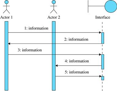
FIGURE 5.22 System sequence diagram.
The activities related to use case analysis still do not deal with objects that are internal to the system. Thus, the system must be represented as a single object: a black box. In this case, it can be represented by the interface symbol ![]() , as proposed by Jacobson et al. (1992). One actor can only communicate with a system through its interface. Messages from the actor cannot reach the objects, as shown in Figure 5.23.
, as proposed by Jacobson et al. (1992). One actor can only communicate with a system through its interface. Messages from the actor cannot reach the objects, as shown in Figure 5.23.
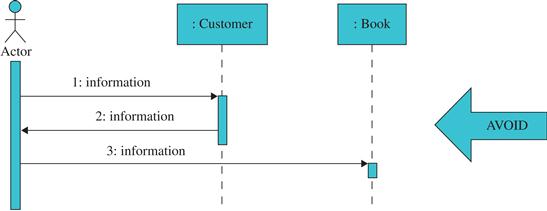
FIGURE 5.23 An example of an inadequate system sequence diagram, where actors communicate directly with the objects.
Actors, interfaces, and other elements of the sequence diagram have a lifeline, represented by a vertical line, where events may happen. When the line is dashed, the actor or system is inactive. When the line is solid, the element is active (processing or waiting for the result of an operation being performed by another element). Human actors are always considered active.
The horizontal arrows represent the information flow. There are three kinds of information flows in that diagram:
• Between actors: Actors’ communication among themselves, corresponding to complementary steps of the expanded use case.
• From the actors to the system: Corresponding to system events, that is, steps that could be marked with [IN] in expanded use cases.
• From the system to the actors: Corresponding to system returns, that is, steps that could be marked with [OUT] in expanded use cases.
The information exchange between actors does not belong to the scope of the system, but it may be useful to illustrate how information is exchanged from actor to actor until reaching the system.
One thing to keep in mind when these diagrams are being built is that information is not created during the process; it is only transferred from actors to system and vice versa. The actor usually has some information that must be passed to the system in order to perform a process. To process a book order, the customer must inform the system who she is and which books she desires. In the beginning, the customer is the only one who holds that information; the system has the registry of all customers and books, but it cannot know who that specific customer is until someone provides that information.
The sequence diagram can be built for the main flow of a use case and completed with alternate flows. Optionally, different sequence diagrams could be built for each flow. However, the most important thing at the moment is to know what information is exchanged between the actors and the system. The analyst must build a catalog with all system commands and queries (which are explained in the next sections) identified in the main and alternate flows of the use case. This information will be used later to define contracts that indicate how the system retrieves and transforms information (Chapter 8).
5.8.2 Expanded use cases as system sequence diagrams
The system sequence diagram is a tool for achieving more formal and detailed use case descriptions. Additionally, developing the system sequence diagram makes the connection between requirements analysis (the expanded use case) and software design (the system operations that will be implemented).
The construction of the system sequence diagram may be done in two stages:
1. Representing the steps of the use case as information exchange between actors and the system interface.
2. Representing system operations as methods calling between the interface and the façade-controller,7 which encapsulates the domain tier of the system.
The first step is simple: for each use case input (a step that could be marked with [IN]), there is an equivalent system event in which one actor sends information to the interface, and for each use case output (a step that could be marked with [OUT]), there is an equivalent system return in which an actor receives information from the system (Figures 5.24 and 5.25).
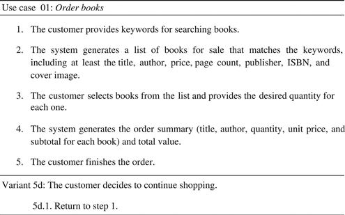
FIGURE 5.24 A reference use case.
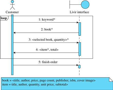
FIGURE 5.25 The representation of a use case main flow as a system sequence diagram.
Note that between actors and interface the flows consist of sending and receiving information. Information may be sent by an actor, for example, by typing it in a form. Information can be received by an actor when it is printed on the screen, for example. At this level, flows are not calling methods because actors are not internal objects.
The words or phrases used in sequence diagram flows to represent information are sometimes a source of confusion and misunderstanding. To avoid such confusion, a labeling pattern is recommended:
• Simple information (alphanumeric data) is represented by one or more words. For example, keyword (step 1 of Figure 5.25), quantity (step 3), and total (step 5).
• Complex information may be represented between “<” and “>” in the diagram if it is composed of a few elements (2 or 3). For example, <selected book, quantity> (step 3).
• Complex information composed of numerous elements (more than 3) may be represented in a separate note or data dictionary.8 Only the name of the complex concept is used in the diagram. For example, book (step 2) and item (step 4).
• A collection of values is indicated by the suffix “*”. For example, keyword* (step 1), book* (step 2), <selected book, quantity>* (step 3), and item* (step 4).
• When one object is selected from a list presented by the system, the selection is indicated by the word “selected,” as in step 3, where “selected book” stands for a book that was selected from the list bookpresented in step 2.
Some other considerations on the diagram may follow:
• In step 1, the team could choose to use keywords instead of keyword*. However, in this case, the fact that the information being sent is a list of words would not follow the proposed notation.
• The information contained in a book is probably a subset of the attributes of the Book class of the conceptual model; it does not necessarily correspond to the complete set of attributes of the Book class.
• In step 3, when the user informs the system about the list of books she has selected it is not necessarily the complete information about a book that is being sent by the user to the system. Technologically speaking, the user just has to select a book from a list and the interface sends to the system the correct identifier for the selected book (the user does not even have to know which identifier it is).
• In step 4, an item was created to represent different aspects of a book: instead of page count, publisher, ISBN, and cover image, an item presents quantity (which is not an attribute of a book), and subtotal (which is calculated from price and quantity).
• Step 5 does not represent alphanumeric information being sent or received as in the previous steps. Finish order is a control step. It just informs the system that the state of the order has changed without passing any other new alphanumeric information.
• Variant 5d is a choice between finishing the order or resuming shopping. It is represented by the loop fragment that includes steps 1 to 4.
5.8.3 Connecting the interface to the façade-controller
System events are actions that a user performs over the system interface. When a web interface is used, for example, these actions consist of filling forms, pressing buttons, etc. These are not operations in the sense of programming languages, that is, these flows from an actor to the system and vice versa do not represent method calling.
However, system commands and system queries are computational procedures that are necessary to implement system events and system returns, respectively. System commands and queries are activated by messages that are sent from the interface to the façade-controller. Now, we have a system component that invokes another system component. In this case, it is the interface that sends a message, asking the façade-controller to perform a method that consists of a command or query. The set of all possible messages is equivalent to the whole functionality of the system: all access and updating of the logic for data is done by system commands and queries.
Thus, four kinds of arrows are of interest in system sequence diagrams:
• System event: As shown in Figure 5.26, this is an action performed by an actor that sends some information to the system. In the diagram, it is represented by an arrow from the actor to the interface.
• System return: As shown in Figure 5.27, this is a flow of information from the system to one actor, represented in the diagram as an arrow from the interface to the actor.
• System command: As shown in Figure 5.28, this is a message that is sent from the interface to the controller, usually in response to a system event. The system command must, by definition, change some information stored or managed by the system. In the diagram, this is represented by an arrow from the interface to the controller labeled with a message (the use of parentheses is always recommended to distinguish it from information flows, such as system events and returns).
• System query: As seen in Figure 5.29, this is a message that is sent from the interface to the controller in order to obtain some information from the system. Queries must not change data; they just return data. In the diagram, queries are represented by arrows from the interface to the controller labeled with a message with an explicit return value.
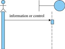
FIGURE 5.26 System event.
FIGURE 5.27 System return.
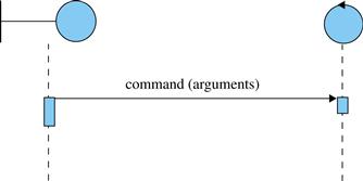
FIGURE 5.28 System command.
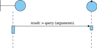
FIGURE 5.29 System query.
Query results could also be represented by dashed lines from the controller to the interface, as shown in Figure 5.30. Both representations are allowed and the team may choose one or the other. The approach of Figure 5.29 creates fewer arrows in the diagram, but may be complicated if complex data must be returned by the query. That problem can be minimized if notes such as those of Figure 5.25 are used to define complex data. Other analysts would prefer the approach of Figure 5.30, which makes the return appear explicitly as an arrow in the diagram. The disadvantage of this approach is that it splits a single query call into two arrows.
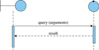
FIGURE 5.30 Alternate representation of a system query.
Communication between actors can be represented in the system sequence diagram as arrows from one actor to another. However, as explained before, these communications do not affect the implementation of the system.
The domain tier of an application (the part of the system that contains all classes that perform the logical operations on data) is encapsulated by its façade-controller, which is an instance of a class that implements all system commands and queries that must be accessed by a given interface or set of interfaces. There are at least three subpatterns for the façade-controller. The first one, for smaller systems, consists of implementing a single controller for the whole system. However, this would result in a large number of operations implemented in a single class. A solution to this is to divide it into use case controllers, that is, a different controller class for each use case. However, this is not a good solution when different use cases call the same methods, which should be implemented in different classes. The most adequate solution for most medium or large systems is to implement component or subsystem controllers, that is, controllers that encapsulate the functionality of subsystems or components as defined by the system architecture.
The design of messages between the interface and the controller is made after an examination of the system events and returns using the following rules:
• A system event that sends data to the system that must be stored, updated, or deleted, that is, data that causes a change in the internal state of the system, requires at least one system command (Figure 5.31).
• A system return that sends data from the system to the user requires at least one system query, so that the data can be obtained from the controller in order to be presented by the interface (Figure 5.32).
• A sequence of system event and return, where the event just provides arguments for producing the return, requires a system query where the information received from the system event are the arguments (Figure 5.33).
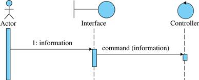
FIGURE 5.31 A system event that requires a system command.
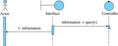
FIGURE 5.32 A system return that requires a system query.
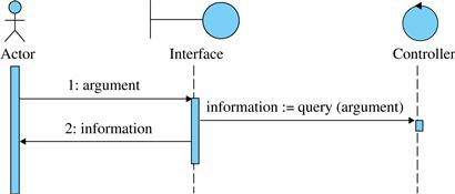
FIGURE 5.33 A sequence of system event and system return that requires a system query as the event just passes its arguments.
The cause/consequence relation between events and commands and between returns and queries is not always so direct. Sometimes, a query can use arguments that were passed to the interface many steps earlier, or information passed by the actor to the interface can be used many times by different system commands and queries.
These rules for deriving queries and commands from returns and events are just a first approach for designing the interface tier. Later, modeling techniques and design decisions may change the way these commands and queries are invoked.
5.8.4 Stateless strategy
When the system sequence diagram is being developed, each piece of information is passed from the actor to the system once. However, in the next level, between interface and controller, many different commands and queries may need the same arguments. For example, the customer ID may be necessary to perform many subsequent operations. At this point, the designer must decide if the controller must have transient memory for storing these arguments (stateful strategy) or if it is not provided with memory (stateless strategy). In the stateless strategy each time a system query or command needs an argument it has to receive it explicitly from the interface.
Figure 5.34 shows how the system sequence diagram would look for the use case Order books with a stateless strategy. The information is passed from the actor to the interface just once, but each time a system command or query needs that information, the interface must send it again as an argument to the controller. Observe that cartId is passed by the interface to the controller three times: when add2Cart, getCartSummary, and finishOrder are called.
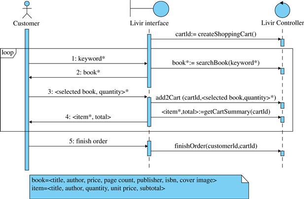
FIGURE 5.34 System sequence diagram for the main flow of use case Order books using a stateless strategy.
From this point it can be seen that the team is making a transition from analysis to design, because design decisions must be made in order to accommodate the requirements. For example, the fact that a user must be identified only when the order is finished prevents the system from creating an order before that point (if the order is really a concept that must be associated to a customer). Therefore, a shopping cart is created instead of an order at the initialization of that sequence diagram. The order will be created only when the user chooses to stop shopping (finishing the order). At that point, if the user is not already identified an exception would be raised, as explained later. One point to notice is that as the controller has no transient memory, it does not register the information of who is shopping. It is the interface that holds the customer identification at this point. When the order is ready to be completed, the interface sends to the controller the IDs of the customer and of the shopping cart (remember that the shopping cart is not yet associated to any customer).
As the controller does not have state (transient memory), each operation sent to it that refers to the shopping cart must refer to its number (cartId). Why is the cart ID used and not the cart object itself? Are we not doing object-oriented design? The point is that the domain objects are encapsulated by the controller. This means that the interface should not have direct access to the domain objects. This is why the interface sends an ID as a parameter instead of the cart object itself.
One remark must be made about the command createShoppingCart: as it creates a new domain object and returns its identification code, one could ask if this is not against the command-query separation principle. It is not. It is one of the acceptable exceptions to that principle, because the command just creates a new object and returns its identification code. It can be made because trying to obtain the code of a newly created object by other means would be counterproductive.
5.8.5 Stateful strategy
When the controller may have transient memory for holding working parameters during the execution of a use case, then we are using the stateful strategy. Thus, after an argument is sent to the controller by an operation, the subsequent operations would not need to receive the argument again; the controller would keep it in local memory.
This argument is not necessarily persistent information, though; the transient information is not stored in a database or other equivalent structure. It consists of transient information only (for example, who is the current customer, which shopping cart is being used, etc.), which is available only during the use case transaction. Figure 5.35 presents the same use case that was shown in Figure 5.34, but this time with the stateful approach. It can be observed that, among other things, it is not necessary to return the new shopping cart identification, because the controller will remember which one it is.
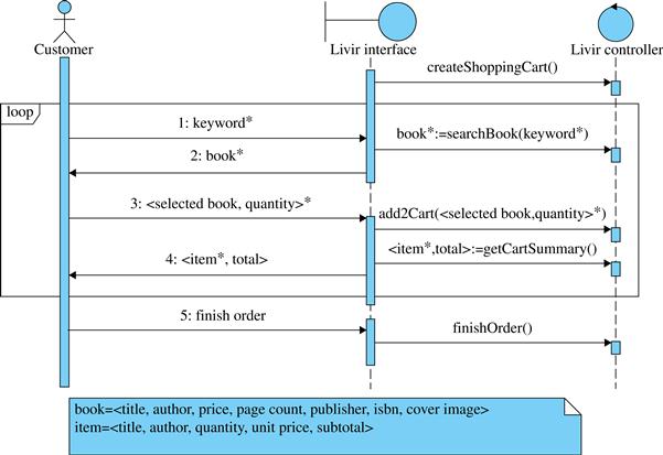
FIGURE 5.35 System sequence diagram for the main flow of use case Order books using stateful strategy.
With the stateful strategy it is not necessary to return the reference to the new shopping cart because the controller has an internal mechanism to store that value. In the same way, the methods add2Cart, getCartSummary, and finishOrder also do not need to receive that argument. It is maintained by the controller. In the same way, the identity of the customer, if known, is maintained by the controller, not by the interface.
One option for implementing this transient memory is to use transient associations, as explained in Section 8.3. It is an architectural decision to choose one or another approach. Some pros and cons of them are the following:
• The stateful strategy demands the implementation of a transient (not persistent) memory mechanism in order to store some parameters (the use of transient associations, for example). The stateless strategy does not demand that kind of mechanism.
• The stateless strategy demands more parameter passing between the interface and the controller. When it is the case of passing information through the network this may be inconvenient. With the stateful strategy information is transmitted just once.
Additionally, it can be said that operations are more reusable with the stateless strategy, because each of them receives all the parameters it needs, without depending on operations that were performed before. Also, the stateless strategy scales better than the stateful one. Systems with many concurrent users would be easier to produce and maintain with stateless strategy.
5.8.6 Alternate flows in system sequence diagrams
As seen at the beginning of this chapter, use case steps, especially system events, may have exceptions, which are handled by an alternate flow.
The insertion of those alternate flows in a system sequence diagram may be done in stages. Initially, the exceptions may be indicated in the diagram as well as where they occur. Then opt fragments can be produced, that is, optional parts as shown in Figure 5.36. The procedure is to take the complete use case as shown in Figure 5.7 and add each exception as an opt fragment at the adequate position of the flow (usually just after the step that could cause the exception).
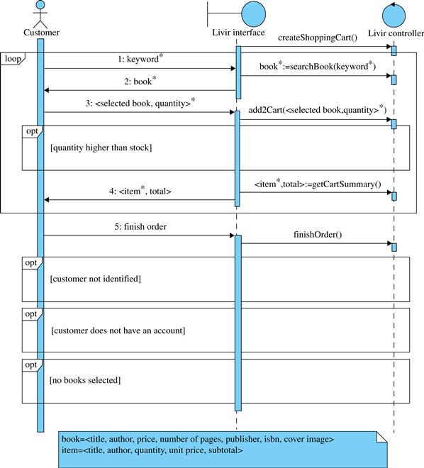
FIGURE 5.36 Sequence diagram with exceptions included.
The diagram of Figure 5.36 shows literally that after step 3 and after step 5 optional events may happen. Those events correspond to exceptions 3a, 5a, 5b, and 6c shown in Figure 5.7.
Now, it is necessary to design what happens inside the optional fragments when each exception is handled. The opt fragment contains the steps of the alternate flow, but it is also important to look carefully at the termination of the alternate flow. Some of the alternate flows return to the step that generated the exception and must be treated as repetitive loops that include the step which caused the exception. Others advance to the next step, and should be treated as just an optional fragment of the diagram. When other use cases are referenced or when a fragment is so long that it justifies its definition in a separate diagram, then the ref fragment may be used, which indicates that another sequence diagram is being called. The ref fragment may receive and return information in the same way a programming function does, and using the same notation, as for example, ref otherDiagram(arguments):result.
Now the diagram of Figure 5.36 is going to be improved with exception handling. This may become a complex task unless some design decisions are made carefully. For example, in step 3, a set of books and respective quantities is sent to the system and only then the quantities are checked. This would require handling an exception where some books are ordered above stock and others are not, which could be inconvenient. Therefore it was decided to change the sequence diagram so that the exception would be checked each time a quantity is provided. Notice that this decision changes a little the way the user perceives the system Figure 5.37, where only the first three steps of the use case are represented for simplicity.
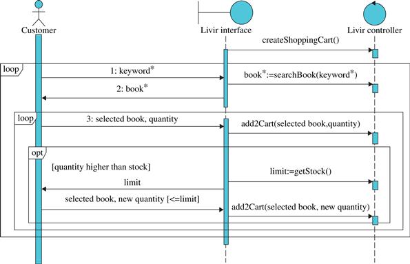
FIGURE 5.37 Part of system sequence diagram with a design change and an exception handler.
Note in Figure 5.37 that the design could be improved again. Why try to perform a command with a quantity that is above stock if the system already knows that information? The information about stock could be returned by the searchBook query so that the interface entry field could already be limited to the real quantity available. That information could also be used by the interface to show books that are in the catalog but not in stock as out of stock. Figure 5.38 shows the resulting design.
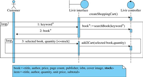
FIGURE 5.38 Part of the system sequence diagram where an exception handler was redesigned.
Observe that in Figure 5.38 the fragment that handles the exception simply disappears. This happened because the exception was changed into a precondition for the system command add2Cart. This is a popular technique to improve design that will be revisited in Chapter 8. The technique consists of preventing the user from sending an invalid argument; the user choice is limited to the valid values. Thus, the exception cannot occur anymore.
Exceptions 5a and 5b may be resolved together as they involve user identification. When the command finishOrder is executed, an exception would occur if the user is not yet identified. The user then has two choices: entering a valid identification or creating a new one. The partial diagram is shown in Figure 5.39.
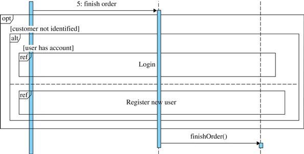
FIGURE 5.39 Dealing with user identification.
As seen in Figure 5.39, it is not necessary to try the command finishOrder in order to discover that the user is not yet identified. The condition may be tested after the user decides to finish the order but before trying the command. Thus, if the user is not identified, she has two options, represented inside the alt fragment. The alt fragment works like an if-then-else: if the user has an account, than she logs in, else she has to create a new account. In both cases, as those sequences may be highly reusable, a reference to another sequence diagram is indicated by the fragment ref.
Finally, exception 5c states that if no book was selected the order cannot be closed. This can be implemented as a loop fragment placed over the flows from 1 to 4 (excluding flow 5) that would repeat until at least one book is selected. As there is already such a loop in the diagram (see Figure 5.37), it is enough to add that condition to the existing loop. The complete sequence diagram with all exceptions handled is shown in Figure 5.40.
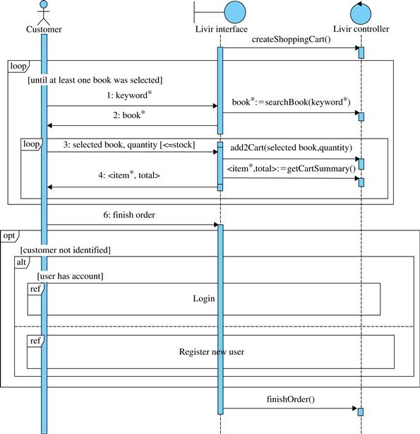
FIGURE 5.40 Complete sequence diagram with exceptions handled.
The main practical result of the system sequence diagram is the discovery and design of the system commands and queries that must be implemented to allow the functionality of the system to be available for the users. According to Figure 5.40, these commands and queries are:9
• createShoppingCart().
• searchBook(keyword*):book*.
• add2Cart(selected book, quantity).
• getCartSummary ():<item*, total>.
• finishOrder().
Chapter 8 shows how to use this information to build a set of contracts that define the whole functionality of the system.
5.9 The process so far
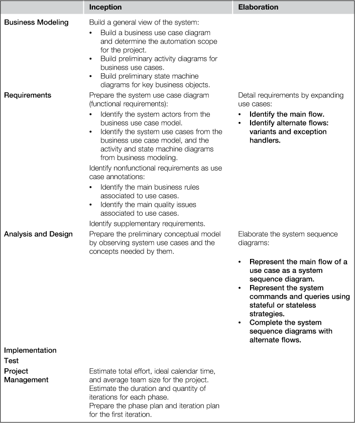
5.10 Questions
1. Variants and exception handlers are alternate flows for a use case. In which situations should one or the other be used?
2. What is the difference between an essential use case and a real use case? Why is the essential use case more interesting for requirements purposes?
3. Explain the differences between mandatory, complementary, and unsuitable use case steps.
4. Expand the main flow of use case 03, Deliver order, presented in Figure 3.10.
5. Finalize the expansion of the use case of Figure 5.2 by indicating its alternate flows.
6. Design the system sequence diagram for the main flow of the use case of Figure 5.2, choosing one of the following strategies: stateless or stateful. After designing the diagram for the main flow, add the alternate flows identified in Question 5.
1http://blog.ivarjacobson.com/use-cases-%E2%80%93-why-successful-and-popular/
2For example, one customer buys two books and another customer buys five books: both actions may be described simply as “customer buys books” because the number of books is irrelevant for understanding the process.
3However, this style for variants must not encourage the reader to do the same with exceptions. As explained in Section 5.3.3, in the case of exceptions there is indeed a normal flow and an alternate one, which must be described outside the main flow; in the case of variants the idea is that they are only different ways to perform the main flow.
4The set {1, 2, 3, …}.
5Here and in further examples in this book the ID provided by a customer is not a system-generated internal code, but the number of a personal document that belongs to the customer. In the United States the social security number could correspond to the ID number, while in other countries other numbers could be used.
6In the past the author ran a project in which a use case that seemed to be a simple CRUD at the beginning happened to be the most complex use case of the whole system in the end.
7A façade-controller provides “a unified interface to a set of interfaces in a subsystem. Façade defines a higher-level interface that makes the subsystem easier to use” (Gamma, Helm, Johnson, & Vlissides, 1995)
8Remember that it is not always the case that complex information exchanged with the system corresponds to the complete set of attributes of a concept of the conceptual model.
9The strategy applied in Figure 5.40 is stateful. If the stateless strategy was used instead, the operations would be slightly different, because they would have more parameters.
All materials on the site are licensed Creative Commons Attribution-Sharealike 3.0 Unported CC BY-SA 3.0 & GNU Free Documentation License (GFDL)
If you are the copyright holder of any material contained on our site and intend to remove it, please contact our site administrator for approval.
© 2016-2026 All site design rights belong to S.Y.A.