OpenGL ES 3.0: Programming Guide, Second Edition (2014)
Chapter 10. Fragment Shaders
Chapter 9, “Texturing,” introduced you to the basics of creating and applying textures in the fragment shader. In this chapter, we provide more details on the fragment shader and describe some of its uses. In particular, we focus on how to implement fixed-function techniques using the fragment shader. The topics we cover in this chapter include the following:
• Fixed function fragment shaders
• Programmable fragment shader overview
• Multitexturing
• Fog
• Alpha test
• User clip planes
In Figure 10-1, we have previously covered the vertex shader, primitive assembly, and rasterization stages of the programmable pipeline. We have talked about using textures in the fragment shader. Now, we focus on the fragment shader portion of the pipeline and fill in the remaining details on writing fragment shaders.
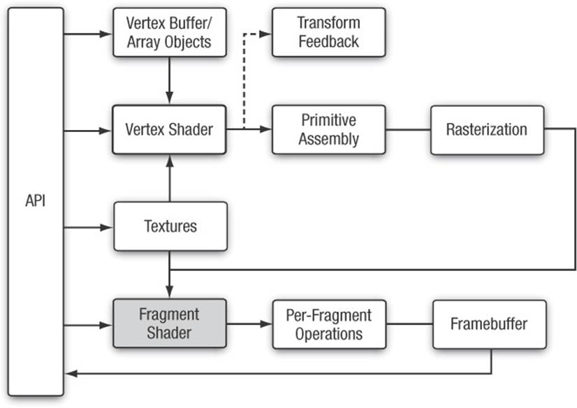
Figure 10-1 OpenGL ES 3.0 Programmable Pipeline
Fixed-Function Fragment Shaders
Readers who are new to the programmable fragment pipeline but have worked with OpenGL ES 1.x (or earlier versions of desktop OpenGL) are probably familiar with the fixed-function fragment pipeline. Before diving into details of the fragment shader, we think it is worthwhile to briefly review the old fixed-function fragment pipeline. This will give you an understanding of how the old fixed-function pipeline maps into fragment shaders. It’s a good way to start before moving into more advanced fragment programming techniques.
In OpenGL ES 1.1 (and fixed-function desktop OpenGL), you had a limited set of equations that could be used to determine how to combine the various inputs to the fragment shader. In the fixed-function pipeline, you essentially had three inputs you could use: the interpolated vertex color, the texture color, and the constant color. The vertex color would typically hold either a precomputed color or the result of the vertex lighting computation. The texture color came from fetching from whichever texture was bound using the primitive’s texture coordinates and the constant color could be set for each texture unit.
The set of equations you could use to combine these inputs together was quite limited. For example, in OpenGL ES 1.1, the equations listed in Table 10-1 were available. The inputs A, B, and C to these equations could come from the vertex color, texture color, or constant color.
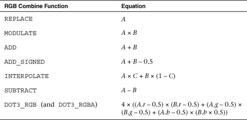
Table 10-1 OpenGL ES 1.1 RGB Combine Functions
There actually was a great number of interesting effects one could achieve, even with this limited set of equations. However, this was far from programmable, as the fragment pipeline could be configured only in a very fixed set of ways.
So why are we reviewing this history here? It helps give an understanding of how traditional fixed-function techniques can be achieved with shaders. For example, suppose we had configured the fixed-function pipeline with a single base texture map that we wanted to modulate (multiply) by the vertex color. In fixed-function OpenGL ES (or OpenGL), we would enable a single texture unit, choose a combine equation of MODULATE, and set up the inputs to the equation to come from the vertex color and texture color. The code to do this in OpenGL ES 1.1 is provided here for reference:
glTexEnvi(GL_TEXTURE_ENV, GL_TEXTURE_ENV_MODE, GL_COMBINE);
glTexEnvi(GL_TEXTURE_ENV, GL_COMBINE_RGB, GL_MODULATE);
glTexEnvi(GL_TEXTURE_ENV, GL_SOURCE0_RGB, GL_PRIMARY_COLOR);
glTexEnvi(GL_TEXTURE_ENV, GL_SOURCEl_RGB, GL_TEXTURE);
glTexEnvi(GL_TEXTURE_ENV, GL_COMBINE_ALPHA, GL_MODULATE);
glTexEnvi(GL_TEXTURE_ENV, GL_SOURCE0_ALPHA, GL_PRIMARY_COLOR);
glTexEnvi(GL_TEXTURE_ENV, GL_SOURCEl_ALPHA, GL_TEXTURE);
This code configures the fixed-function pipeline to perform a modulate (A × B) between the primary color (the vertex color) and the texture color. If this code doesn’t make sense to you, don’t worry, as none of it exists in OpenGL ES 3.0. Rather, we are simply trying to show how this would map to a fragment shader. In a fragment shader, this same modulate computation could be accomplished as follows:
#version 300 es
precision mediump float;
uniform sampler2D s_tex0;
in vec2 v_texCoord;
in vec4 v_primaryColor;
layout(location = 0) out vec4 outColor;
void main()
{
outColor = texture(s_tex0, v_texCoord) * v_primaryColor;
}
The fragment shader performs the exact same operations that would be performed by the fixed-function setup. The texture value is fetched from a sampler (that is bound to texture unit 0) and a 2D texture coordinate is used to look up that value. Then, the result of that texture fetch is multiplied by v_primaryColor, an input value that is passed in from the vertex shader. In this case, the vertex shader would have passed the color to the fragment shader.
It is possible to write a fragment shader that would perform the equivalent computation as any possible fixed-function texture combine setup. It is also possible, of course, to write shaders with much more complex and varied computations than just fixed functions would allow. However, the point of this section was just to drive home how we have transitioned from fixed-function to programmable shaders. Now, we begin to look at some specifics of fragment shaders.
Fragment Shader Overview
The fragment shader provides a general-purpose programmable method for operating on fragments. The inputs to the fragment shader consist of the following:
• Inputs (or varyings)—Interpolated data produced by the vertex shader. The outputs of the vertex shader are interpolated across the primitive and passed to the fragment shader as inputs.
• Uniforms—State used by the fragment shader. These are constant values that do not vary per fragment.
• Samplers—Used to access texture images in the shader.
• Code—Fragment shader source or binary that describes the operations that will be performed on the fragment.
The output of the fragment shader is one or more fragment colors that get passed on to the per-fragment operations portion of the pipeline (the number of output colors depends on how many color attachments are being used). The inputs and outputs to the fragment shader are illustrated inFigure 10-2.
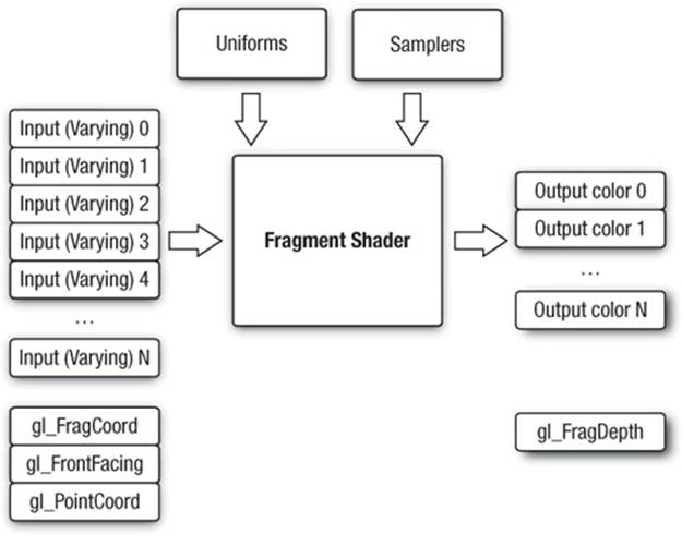
Figure 10-2 OpenGL ES 3.0 Fragment Shader
Built-In Special Variables
OpenGL ES 3.0 has built-in special variables that are output by the fragment shader or are input to the fragment shader. The following built-in special variables are available to the fragment shader:
• gl_FragCoord—A read-only variable that is available in the fragment shader. This variable holds the window relative coordinates (x, y, z, 1/w) of the fragment. There are a number of algorithms where it can be useful to know the window coordinates of the current fragment. For example, you can use the window coordinates as offsets into a texture fetch into a random noise map whose value is used to rotate a filter kernel on a shadow map. This technique is used to reduce shadow map aliasing.
• gl_FrontFacing—A read-only variable that is available in the fragment shader. This boolean variable has a value of true if the fragment is part of a front-facing primitive and false otherwise.
• gl_PointCoord—A read-only variable that can be used when rendering point sprites. It holds the texture coordinate for the point sprite that is automatically generated in the [0, 1] range during point rasterization. In Chapter 14, “Advanced Programming with OpenGL ES 3.0,” there is an example of rendering point sprites that uses this variable.
• gl_FragDepth—A write-only output variable that, when written to in the fragment shader, overrides the fragment’s fixed-function depth value. This functionality should be used sparingly (and only when necessary) because it can disable depth optimization in many GPUs. For example, many GPUs have a feature called Early-Z where the depth test is performed ahead of executing the fragment shader. The benefit of using Early-Z is that fragments that fail the depth test are never shaded (thus saving performance). However, when gl_FragDepth is used, this feature must be disabled because the GPU does not know the depth value ahead of executing the fragment shader.
Built-In Constants
The following built-in constants are also relevant to the fragment shader:
const mediump int gl_MaxFragmentInputVectors = 15;
const mediump int gl_MaxTextureImageUnits = 16;
const mediump int gl_MaxFragmentUniformVectors = 224;
const mediump int gl_MaxDrawBuffers = 4;
const mediump int gl_MinProgramTexelOffset = -8;
const mediump int gl_MaxProgramTexelOffset = 7;
The built-in constants describe the following maximum terms:
• gl_MaxFragmentInputVectors—The maximum number of fragment shader inputs (or varyings). The minimum value supported by all ES 3.0 implementations is 15.
• gl_MaxTextureImageUnits—The maximum number of texture image units that are available. The minimum value supported by all ES 3.0 implementations is 16.
• gl_MaxFragmentUniformVectors—The maximum number of vec4 uniform entries that can be used inside a fragment shader. The minimum value supported by all ES 3.0 implementations is 224. The number of vec4 uniform entries that can actually be used by a developer can vary from implementation to implementation and from one fragment shader to another. This issue is described in Chapter 8, “Vertex Shaders,” and the same issue applies to fragment shaders.
• gl_MaxDrawBuffers—The maximum number of multiple render targets (MRTs) supported. The minimum value supported by all ES 3.0 implementations is 4.
• gl_MinProgramTexelOffset/gl_MaxProgramTexelOffset—The minimum and maximum offsets supported by the offset parameter to the texture*Offset() built-in ESSL functions.
The values specified for each built-in constant are the minimum values that must be supported by all OpenGL ES 3.0 implementations. It is possible that implementations may support values greater than the minimum values described. The actual hardware-dependent values for fragment shader built-in values can also be queried from API code. The following code shows how you would query the values of gl_MaxTextureImageUnits and gl_MaxFragmentUniformVectors:
GLint maxTextureImageUnits, maxFragmentUniformVectors;
glGetIntegerv(GL_MAX_TEXTURE_IMAGE_UNITS,
&maxTextureImageUnits);
glGetIntegerv(GL_MAX_FRAGMENT_UNIFORM_VECTORS
&maxFragmentUniformVectors);
Precision Qualifiers
Precision qualifiers were briefly introduced in Chapter 5, “OpenGL ES Shading Language” and were covered in detail in Chapter 8, “Vertex Shaders.” Please review those sections for full details on precision qualifiers. We remind you here that there is no default precision for fragment shaders. As a consequence, every fragment shader must declare a default precision (or provide precision qualifiers for all variable declarations).
Implementing Fixed-Function Techniques Using Shaders
Now that we have given an overview of fragment shaders, we will demonstrate how to implement several fixed-function techniques using shaders. The fixed-function pipeline in OpenGL ES l.x and desktop OpenGL provided APIs to perform multitexturing, fog, alpha test, and user clip planes. Although none of these techniques is provided explicitly in OpenGL ES 3.0, all of them can still be implemented using shaders. This section reviews each of these fixed-function processes and provides example fragment shaders that demonstrate each technique.
Multitexturing
We start with multitexturing, which is a very common operation in fragment shaders used for combining multiple texture maps. For example, a technique that has been used in many games, such as Quake III, is to store precomputed lighting from radiosity calculations in a texture map. That map is then combined with the base texture map in the fragment shader to represent static lighting. Many other examples of using multiple textures exist, some of which we cover in Chapter 14, “Advanced Programming with OpenGL ES 3.0.” For example, often a texture map is used to store a specular exponent and mask to attenuate and mask specular lighting contributions. Many games also use normal maps, which are textures that store normal information at a higher level of detail than per-vertex normals so that lighting can be computed in the fragment shader.
The point of mentioning this information here is to highlight that you have now learned about all of the parts of the API that are needed to accomplish multitexturing techniques. In Chapter 9, “Texturing,” you learned how to load textures on various texture units and fetch from them in the fragment shader. Combining the textures in various ways in the fragment shader is simply a matter of employing the many operators and built-in functions that exist in the shading language. Using these techniques, you can easily achieve all of the effects that were made possible with the fixed-function fragment pipeline in previous versions of OpenGL ES.
An example of using multiple textures is provided in the Chapter_10/MultiTexture example, which renders the image in Figure 10-3.

Figure 10-3 Multitextured Quad
This example loads a base texture map and light map texture and combines them in the fragment shader on a single quad. The fragment shader for the sample program is provided in Example 10-1.
Example 10-1 Multitexture Fragment Shader
#version 300 es
precision mediump float;
in vec2 v_texCoord;
layout(location = 0) out vec4 outColor;
uniform sampler2D s_baseMap;
uniform sampler2D s_lightMap;
void main()
{
vec4 baseColor;
vec4 lightColor;
baseColor = texture( s_baseMap, v_texCoord );
lightColor = texture( s_lightMap, v_texCoord );
// Add a 0.25 ambient light to the texture light color
outColor = baseColor * (lightColor + 0.25);
}
The fragment shader has two samplers, one for each of the textures. The relevant code for setting up the texture units and samplers follows.
// Bind the base map
glActiveTexture(GL_TEXTURE0);
glBindTexture(GL_TEXTURE_2D, userData->baseMapTexId);
// Set the base map sampler to texture unit 0
glUniformli(userData->baseMapLoc, 0);
// Bind the light map
glActiveTexture(GL_TEXTUREl);
glBindTexture(GL_TEXTURE_2D, userData->lightMapTexId);
// Set the light map sampler to texture unit 1
glUniformli(userData->lightMapLoc, 1);
As you can see, this code binds each of the individual texture objects to textures units 0 and 1. The samplers are set with values to bind the samplers to the respective texture units. In this example, a single texture coordinate is used to fetch from both of the maps. In typical light mapping, there would be a separate set of texture coordinates for the base map and light map. The light maps are typically paged into a single large texture and the texture coordinates can be generated using offline tools.
Fog
A common technique that is used in rendering 3D scenes is the application of fog. In OpenGL ES 1.1, fog was provided as a fixed-function operation. One of the reasons fog is such a prevalent technique is that it can be used to reduce draw distances and remove “popping” of geometry as it comes in closer to the viewer.
There are a number of possible ways to compute fog, and with programmable fragment shaders you are not limited to any particular equation. Here we show how you would go about computing linear fog with a fragment shader. To compute any type of fog, we will need two inputs: the distance of the pixel to the eye and the color of the fog. To compute linear fog, we also need the minimum and maximum distance range that the fog should cover.
The equation for the linear fog factor
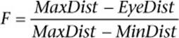
computes a linear fog factor to multiply the fog color by. This color gets clamped in the [0.0, 1.0] range and then is linear interpolated with the overall color of a fragment to compute the final color. The distance to the eye is best computed in the vertex shader and interpolated across the primitive using a varying variable.
A PVRShaman (.POD) workspace is provided as an example in the Chapter_10/PVR_LinearFog folder that demonstrates the fog computation. Figure 10-4 is a screenshot of the workspace. PVRShaman is a shader development integrated development environment (IDE) that is part of the Imagination Technologies PowerVR SDK downloadable from http://powervrinsider.com/. Several subsequent examples in the book use PVRShaman to demonstrate various shading techniques.
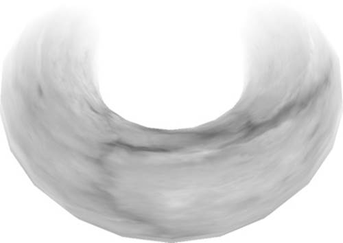
Figure 10-4 Linear Fog on Torus in PVRShaman
Example 10-2 provides the code for the vertex shader that computes the distance to the eye.
Example 10-2 Vertex Shader for Computing Distance to Eye
#version 300 es
uniform mat4 u_matViewProjection;
uniform mat4 u_matView;
uniform vec4 u_eyePos;
in vec4 a_vertex;
in vec2 a_texCoord0;
out vec2 v_texCoord;
out float v_eyeDist;
void main( void )
{
// Transform vertex to view space
vec4 vViewPos = u_matView * a_vertex;
// Compute the distance to eye
v_eyeDist = sqrt( (vViewPos.x - u_eyePos.x) *
(vViewPos.x - u_eyePos.x) +
(vViewPos.y - u_eyePos.y) *
(vViewPos.y - u_eyePos.y) +
(vViewPos.z - u_eyePos.z) *
(vViewPos.z - u_eyePos.z) );
gl_Position = u_matViewProjection * a_vertex;
v_texCoord = a_texCoord0.xy;
}
The important part of this vertex shader is the computation of the v_eyeDist vertex shader output variable. First, the input vertex is transformed into view space using the view matrix and stored in vViewPos. Then, the distance from this point to the u_eyePos uniform variable is computed. This computation gives us the distance in eye space from the viewer to the transformed vertex. We can use this value in the fragment shader to compute the fog factor, as shown in Example 10-3.
Example 10-3 Fragment Shader for Rendering Linear Fog
#version 300 es
precision mediump float;
uniform vec4 u_fogColor;
uniform float u_fogMaxDist;
uniform float u_fogMinDist;
uniform sampler2D baseMap;
in vec2 v_texCoord;
in float v_eyeDist;
layout( location = 0 ) out vec4 outColor;
float computeLinearFogFactor()
{
float factor;
// Compute linear fog equation
factor = (u_fogMaxDist − v_eyeDist) /
(u_fogMaxDist − u_fogMinDist );
// Clamp in the [0, 1] range
factor = clamp( factor, 0.0, 1.0 );
return factor;
}
void main( void )
{
float fogFactor = computeLinearFogFactor();
vec4 baseColor = texture( baseMap, v_texCoord );
// Compute final color as a lerp with fog factor
outColor = baseColor * fogFactor +
u_fogColor * (1.0 − fogFactor);
}
In the fragment shader, the computeLinearFogFactor() function performs the computation for the linear fog equation. The minimum and maximum fog distances are stored in uniform variables, and the interpolated eye distance that was computed in the vertex shader is used to compute the fog factor. The fog factor is then used to perform a linear interpolation (abbreviated as “lerp” in Example 10-3) between the base texture color and the fog color. The result is that we now have linear fog and can easily adjust the distances and colors by changing the uniform values.
Note that with the flexibility of programmable fragment shaders, it is very easy to implement other methods to compute fog. For example, you could easily compute exponential fog by simply changing the fog equation. Alternatively, rather than compute fog based on distance to the eye, you could compute fog based on distance to the ground. A number of possible fog effects can be easily achieved with small modifications to the fog computations provided here.
Alpha Test (Using Discard)
A common effect used in 3D applications is to draw primitives that are fully transparent in certain fragments. This is very useful for rendering something like a chain-link fence. Representing a fence using geometry would require a significant amount of primitives. However, an alternative to using geometry is to store a mask value in a texture that specifies which texels should be transparent. For example, you could store the chain-link fence in a single RGBA texture, where the RGB values represent the color of the fence and the A value represents the mask of whether the texture is transparent. Then you could easily render a fence using just one or two triangles and masking off pixels in the fragment shader.
In traditional fixed-function rendering, this effect was achieved using the alpha test. The alpha test allowed you to specify a comparison test whereby if comparison of an alpha value of a fragment with a reference value failed, that fragment would be killed. That is, if a fragment failed the alpha test, the fragment would not be rendered. In OpenGL ES 3.0, there is no fixed-function alpha test, but the same effect can be achieved in the fragment shader using the discard keyword.
The PVRShaman example in Chapter_10/PVR_AlphaTest gives a very simple example of doing the alpha test in the fragment shader, as shown in Figure 10-5.
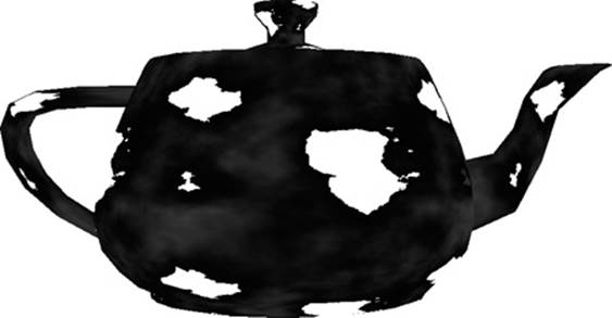
Figure 10-5 Alpha Test Using Discard
Example 10-4 gives the fragment shader code for this example.
Example 10-4 Fragment Shader for Alpha Test Using Discard
#version 300 es
precision mediump float;
uniform sampler2D baseMap;
in vec2 v_texCoord;
layout( location = 0 ) out vec4 outColor;
void main( void )
{
vec4 baseColor = texture( baseMap, v_texCoord );
// Discard all fragments with alpha value less than 0.25
if( baseColor.a < 0.25 )
{
discard;
}
else
{
outColor = baseColor;
}
}
In this fragment shader, the texture is a four-channel RGBA texture. The alpha channel is used for the alpha test. The alpha color is compared with 0.25; if it is less than that value, the fragment is killed using discard. Otherwise, the fragment is drawn using the texture color. This technique can be used for implementing the alpha test by simply changing the comparison or alpha reference value.
User Clip Planes
As described in Chapter 7, “Primitive Assembly and Rasterization,” all primitives are clipped against the six planes that make up the view frustum. However, sometimes a user might want to clip against one or more additional user clip planes. There are a number of reasons why you might want to clip against user clip planes. For example, when rendering reflections, you need to flip the geometry about the reflection plane and then render it into an off-screen texture. When rendering into the texture, you need to clip the geometry against the reflection plane, which requires a user clip plane.
In OpenGL ES 1.1, user clip planes could be provided to the API via a plane equation and the clipping would be handheld automatically. In OpenGL ES 3.0, you can still accomplish this same effect, but now you need to do it yourself in the shader. The key to implementing user clip planes is using the discard keyword, which was introduced in the previous section.
Before showing you how to implement user clip planes, let’s review the basics of the mathematics. A plane is specified by the equation
Ax + By + Cz + D = 0
The vector (A, B, C) represents the normal of the plane and the value D is the distance of the plane along that vector from the origin. To figure out whether a point should or should not be clipped against a plane, we need to evaluate the distance from a point P to a plane with the equation
Dist = (A × P·x) + (B × P·y) + (C × P·z) + D
If the distance is less than 0, we know the point is behind the plane and should be clipped. If the distance is greater than or equal to 0, it should not be clipped. Note that the plane equation and P must be in the same coordinate space. A PVRShaman example is provided in theChapter_10/PVR_ClipPlane workspace and illustrated in Figure 10-6. In the example, a teapot is rendered and clipped against a user clip plane.

Figure 10-6 User Clip Plane Example
The first thing the shader needs to do is compute the distance to the plane, as mentioned earlier. This could be done in either the vertex shader (and passed into a varying) or the fragment shader. It is cheaper in terms of performance to do this computation in the vertex shader rather than having to compute the distance in every fragment. The vertex shader listing in Example 10-5 shows the distance-to-plane computation.
Example 10-5 User Clip Plane Vertex Shader
#version 300 es
uniform vec4 u_clipPlane;
uniform mat4 u_matViewProjection;
in vec4 a_vertex;
out float v_clipDist;
void main( void )
{
// Compute the distance between the vertex and
// the clip plane
v_clipDist = dot( a_vertex.xyz, u_clipPlane.xyz ) +
u_clipPlane.w;
gl_Position = u_matViewProjection * a_vertex;
}
The u_clipPlane uniform variable holds the plane equation for the clip plane and is passed into the shader using glUniform4f. The v_clipDist varying variable then stores the computed clip distance. This value is passed into the fragment shader, which uses the interpolated distance to determine whether the fragment should be clipped, as shown in Example 10-6.
Example 10-6 User Clip Plane Fragment Shader
#version 300 es
precision mediump float;
in float v_clipDist;
layout( location = 0 ) out vec4 outColor;
void main( void )
{
// Reject fragments behind the clip plane
if( v_clipDist < 0.0 )
discard;
outColor = vec4( 0.5, 0.5, 1.0, 0.0 );
}
As you can see, if the v_clipDist varying variable is negative, this means the fragment is behind the clip plane and must be discarded. Otherwise, the fragment is processed as usual. This simple example just demonstrates the computations needed to implement user clip planes. You can easily implement multiple user clip planes by simply computing multiple clip distances and having multiple discard tests.
Summary
This chapter introduced implementing several rendering techniques using fragment shaders. We focused on implementing fragment shaders that accomplish techniques that were part of fixed-function OpenGL ES 1.1. Specifically, we showed you how to implement multitexturing, linear fog, alpha test, and user clip planes. The number of shading techniques that become possible when using programmable fragment shaders is nearly limitless. This chapter gave you grounding in how to develop some fragment shaders that you can build on to create more sophisticated effects.
Now we are just ready to introduce a number of advanced rendering techniques. The next topics to cover before getting there are what happens after the fragment shader—namely, per-fragment operations and framebuffer objects. These topics are covered in the next two chapters.
All materials on the site are licensed Creative Commons Attribution-Sharealike 3.0 Unported CC BY-SA 3.0 & GNU Free Documentation License (GFDL)
If you are the copyright holder of any material contained on our site and intend to remove it, please contact our site administrator for approval.
© 2016-2026 All site design rights belong to S.Y.A.