OpenGL ES 3.0: Programming Guide, Second Edition (2014)
Chapter 11. Fragment Operations
This chapter discusses the operations that can be applied either to the entire framebuffer or to individual fragments after the execution of the fragment shader in the OpenGL ES 3.0 fragment pipeline. As you’ll recall, the output of the fragment shader is the fragment’s colors and depth value. The following operations occur after fragment shader execution and can affect the visibility and final color of a pixel:
• Scissor box testing
• Stencil buffer testing
• Depth buffer testing
• Multisampling
• Blending
• Dithering
The tests and operations that a fragment goes through on its way to the framebuffer are shown in Figure 11-1.
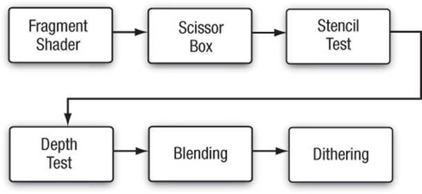
Figure 11-1 The Post-Shader Fragment Pipeline
As you might have noticed, there isn’t a stage named “multisampling.” Multisampling is an anti-aliasing technique that duplicates operations at a subfragment level. We describe how multisampling affects fragment processing in more depth later in the chapter.
The chapter concludes with a discussion of methods for reading pixels from and writing pixels to the framebuffer.
Buffers
OpenGL ES supports three types of buffers, each of which stores different data for every pixel in the framebuffer:
• Color buffer (composed of front and back color buffers)
• Depth buffer
• Stencil buffer
The size of a buffer—commonly referred to as the “depth of the buffer” (but not to be confused with the depth buffer)—is measured by the number of bits that are available for storing information for a single pixel. The color buffer, for example, will have three components for storing the red, green, and blue color components, and optional storage for the alpha component. The depth of the color buffer is the sum of the number of bits for all of its components. For the depth and stencil buffers, in contrast, a single value represents the bit depth of a pixel in those buffers. For example, a depth buffer might have 16 bits per pixel. The overall size of the buffer is the sum of the bit depths of all of the components. Common framebuffer depths include 16-bit RGB buffers, with 5 bits for red and blue, and 6 bits for green (the human visual system is more sensitive to green than to red or blue), and 32 bits divided equally for an RGBA buffer.
Additionally, the color buffer may be double buffered, such that it contains two buffers: one that is displayed on the output device (usually a monitor or LCD display), named the “front” buffer; and another buffer that is hidden from the viewer, but used for constructing the next image to be displayed, and called the “back” buffer. In double-buffered applications, animation is accomplished by drawing into the back buffer, and then swapping the front and back buffers to display the new image. This swapping of buffers is usually synchronized with the refresh cycle of the display device, which will give the illusion of a continuously smooth animation. Recall that double buffering was discussed in Chapter 3, “An Introduction to EGL.”
Although every EGL configuration will have a color buffer, the depth and stencil buffers are optional. However, every EGL implementation must provide at least one configuration that contains all three of the buffers, with the depth buffer being at least 16 bits deep, and at least 8 bits for the stencil buffer.
Requesting Additional Buffers
To include a depth or stencil buffer along with your color buffer, you need to request them when you specify the attributes for your EGL configuration. As discussed in Chapter 3, you pass a set of attribute–value pairs into the EGL that specify the type of rendering surface your application needs. To include a depth buffer in addition to the color buffer, you would specify EGL_DEPTH_SIZE in the list of attributes along with the desired bit depth you need. Likewise, you would add EGL_STENCIL_SIZE along with the number of required bits to obtain a stencil buffer.
Our convenience library, esUtil, simplifies those operations by merely allowing you to say that you would like those buffers along with a color buffer, and it takes care of the rest of the work (requesting a maximally sized buffer). When using our library, you would add (by means of a bit-wise or operation) ES_WINDOW_DEPTH and ES_WINDOW_STENCIL in your call to esCreateWindow. For example,
esCreateWindow ( &esContext, "Application Name",
window_width, window_height,
ES_WINDOW_RGB | ES_WINDOW_DEPTH |
ES_WINDOW_STENCIL );
Clearing Buffers
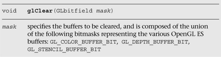
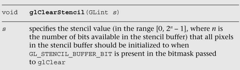
OpenGL ES is an interactive rendering system, and it assumes that at the start of each frame, you’ll want to initialize all of the buffers to their default value. Buffers are cleared by calling the glClear function, which takes a bitmask representing the various buffers that should be cleared to their specified clear values.
You’re required neither to clear every buffer nor to clear them all at the same time, but you might obtain the best performance by calling glClear only once per frame with all the buffers you want simultaneously cleared.
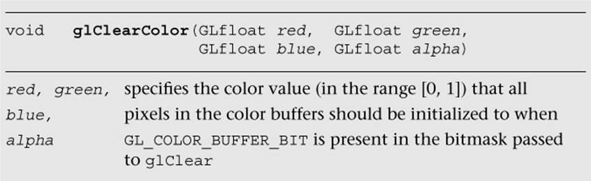
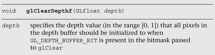
Each buffer has a default value that’s used when you request that buffer be cleared. For each buffer, you can specify your desired clear value using the functions shown here:
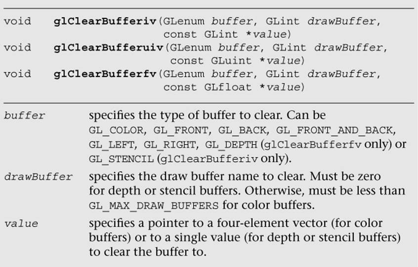
If you have multiple draw buffers in a framebuffer object (see the Multiple Render Targets section), you can clear a specific draw buffer with the following calls:
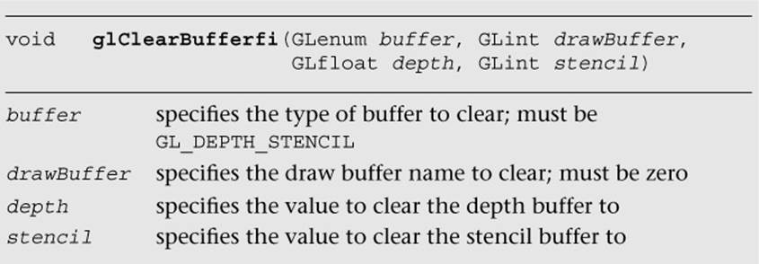
To reduce the number of function calls, you can clear the depth and stencil buffers at the same time using glClearBufferfi.
Using Masks to Control Writing to Framebuffers
You can also control which buffers, or components, in the case of the color buffer, are writable by specifying a buffer write mask. Before a pixel’s value is written into a buffer, the buffer’s mask is used to verify that the buffer is writable.
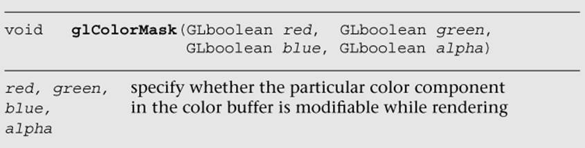
For the color buffer, the glColorMask routine specifies which components in the color buffer will be updated if a pixel is written. If the mask for a particular component is set to GL_FALSE, that component will not be updated if written to. By default, all color components are writable.
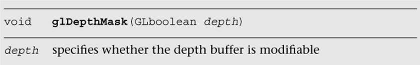
Likewise, writing to the depth buffer is controlled by calling glDepthMask with GL_TRUE or GL_FALSE to specify whether the depth buffer is writable.
Often, writing to the depth buffer is disabled when rendering translucent objects. Initially, you would render all of the opaque objects in the scene with writing to the depth buffer enabled (i.e., set to GL_TRUE). This would ensure that all of the opaque objects are correctly depth sorted, and the depth buffer contains the appropriate depth information for the scene. Then, before rendering the translucent objects, you would disable writing to the depth buffer by calling glDepthMask (GL_FALSE). While writing to the depth buffer is disabled, values can still be read from it and used for depth comparisons. This allows translucent objects that are obscured by opaque objects to be correctly depth buffered, but does not modify the depth buffer such that opaque objects would be obscured by translucent ones.
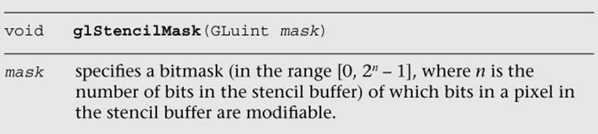
Finally, you can disable writing to the stencil buffer by calling glStencilMask. Unlike with glColorMask or glDepthMask, you can specify which bits of the stencil buffer are writable by providing a mask.
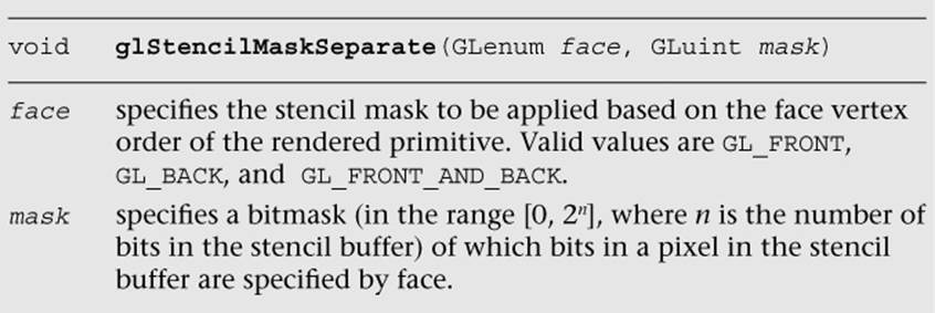
The glStencilMaskSeparate routine allows you to set the stencil mask based on the face vertex order (sometimes called “facedness”) of the primitive. This allows different stencil masks for front- and back-facing primitives. glStencilMaskSeparate(GL_FRONT_AND_BACK, mask) is identical to calling glStencilMask, which sets the same mask for the front and back polygon faces.
Fragment Tests and Operations
The following sections describe the various tests that can be applied to a fragment in OpenGL ES. By default, all fragment tests and operations are disabled, and fragments become pixels as they are written to the framebuffer in the order in which they are received. By enabling the various fragments, operational tests can be applied to choose which fragments become pixels and affect the final image.
Each fragment test is individually enabled by calling glEnable with the appropriate token listed in Table 11-1.
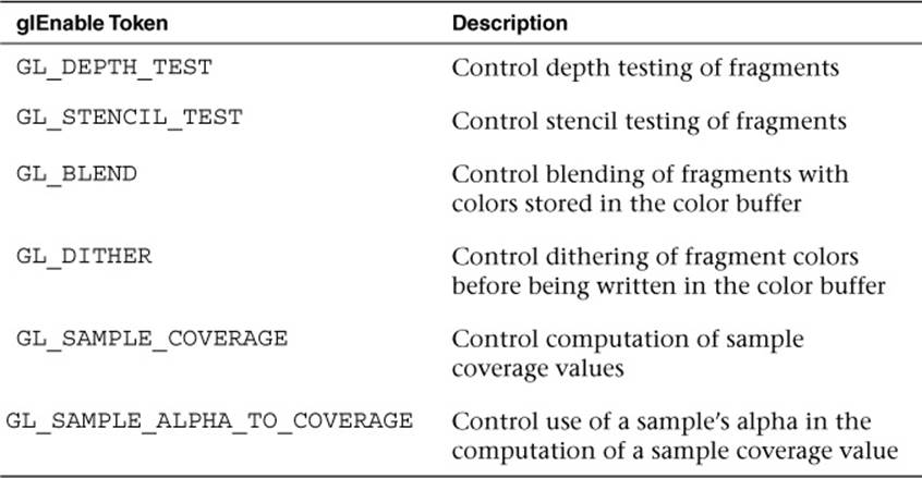
Table 11-1 Fragment Test Enable Tokens
Using the Scissor Test
The scissor test provides an additional level of clipping by specifying a rectangular region that further limits which pixels in the framebuffer are writable. Using the scissor box is a two-step process. First, you need to specify the rectangular region using the glScissor function.
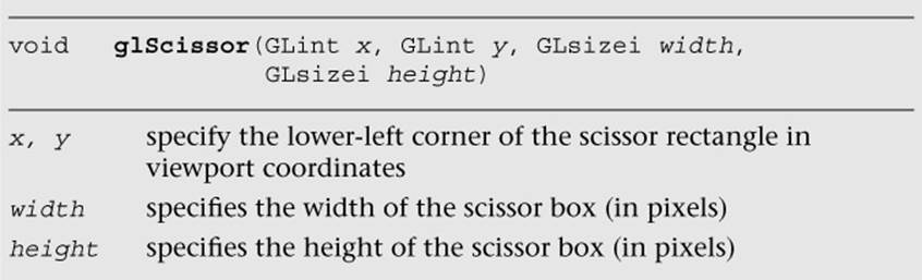
After specifying the scissor box, you need to enable it by calling glEnable(GL_SCISSOR_TEST) to employ the additional clipping. All rendering, including clearing the viewport, is restricted to the scissor box.
Generally, the scissor box is a subregion in the viewport, but the two regions are not required to actually intersect. When the two regions do not intersect, the scissoring operation will be performed on pixels that are rendered outside of the viewport region. Note that the viewporttransformation happens before the fragment shader stage, while the scissor test happens after the fragment shader stage.
Stencil Buffer Testing
The next operation that might be applied to a fragment is the stencil test. The stencil buffer is a per-pixel mask that holds values that can be used to determine whether a pixel should be updated. The stencil test is enabled or disabled by the application.
Using the stencil buffer can be considered a two-step operation. The first step is to initialize the stencil buffer with the per-pixel masks, which is done by rendering geometry and specifying how the stencil buffer should be updated. The second step is generally to use those values to control subsequent rendering into the color buffer. In both cases, you specify how the parameters are to be used in the stencil test.
The stencil test is essentially a bit test, as you might do in a C program where you use a mask to determine if a bit is set, for example. The stencil function, which controls the operator and values of the stencil test, is controlled by the glStencilFunc or glStencilFuncSeparatefunctions.
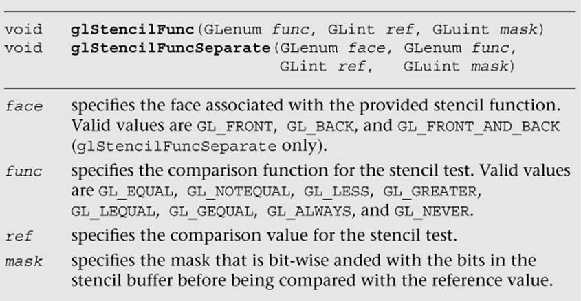
To allow finer control of the stencil test, a masking parameter is used to select which bits of the stencil values should be considered for the test. After selecting those bits, their value is compared with a reference value using the operator provided. For example, to specify that the stencil test passes where the lowest three bits of the stencil buffer are equal to 2, you would call
glStencilFunc ( GL_EQUAL, 2, 0x7 );
and enable the stencil test. Note that in binary format, the last three bits of 0x7 are 111.
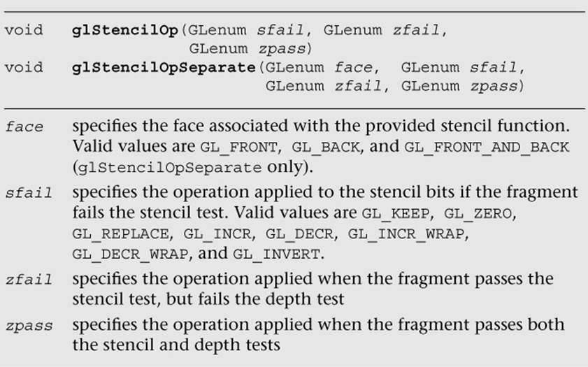
With the stencil test configured, you generally also need to let OpenGL ES 3.0 know what to do with the values in the stencil buffer when the stencil test passes. In fact, modifying the values in the stencil buffer relies on more than just the stencil tests, but also incorporates the results of the depth test (discussed in the next section). Three possible outcomes can occur for a fragment with the combined stencil and depth tests:
1. The fragment fails the stencil tests. If this occurs, no further testing (i.e., the depth test) is applied to that fragment.
2. The fragment passes the stencil test, but fails the depth test.
3. The fragment passes both the stencil and depth tests.
Each of those possible outcomes can be used to affect the value in the stencil buffer for that pixel location. The glStencilOp and glStencilOpSeparate functions control the actions done on the stencil buffer’s value for each of those test outcomes, and the possible operations on the stencil values are shown in Table 11-2.
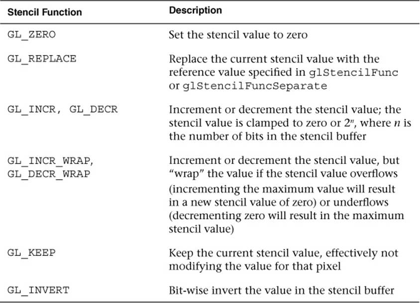
Table 11-2 Stencil Operations
The following example illustrates using glStencilFunc and glStencilOp to control rendering in various parts of the viewport:
GLfloat vVertices[] =
{
−0.75f, 0.25f, 0.50f, // Quad #0
−0.25f, 0.25f, 0.50f,
−0.25f, 0.75f, 0.50f,
−0.75f, 0.75f, 0.50f,
0.25f, 0.25f, 0.90f, // Quad #1
0.75f, 0.25f, 0.90f,
0.75f, 0.75f, 0.90f,
0.25f, 0.75f, 0.90f,
−0.75f, −0.75f, 0.50f, // Quad #2
−0.25f, −0.75f, 0.50f,
−0.25f, −0.25f, 0.50f,
−0.75f, −0.25f, 0.50f,
0.25f, −0.75f, 0.50f, // Quad #3
0.75f, −0.75f, 0.50f,
0.75f, −0.25f, 0.50f,
0.25f, −0.25f, 0.50f,
−1.00f, −1.00f, 0.00f, // Big Quad
1.00f, −1.00f, 0.00f,
1.00f, 1.00f, 0.00f,
−1.00f, 1.00f, 0.00f
};
GLubyte indices[][6] =
{
{ 0, 1, 2, 0, 2, 3 }, // Quad #0
{ 4, 5, 6, 4, 6, 7 }, // Quad #1
{ 8, 9, 10, 8, 10, 11 }, // Quad #2
{ 12, 13, 14, 12, 14, 15 }, // Quad #3
{ 16, 17, 18, 16, 18, 19 } // Big Quad
};
#define NumTests 4
GLfloat colors[NumTests][4] =
{
{ 1.0f, 0.0f, 0.0f, 1.0f },
{ 0.0f, 1.0f, 0.0f, 1.0f },
{ 0.0f, 0.0f, 1.0f, 1.0f },
{ 1.0f, 1.0f, 0.0f, 0.0f }
};
GLint numStencilBits;
GLuint stencilValues[NumTests] =
{
0x7, // Result of test 0
0x0, // Result of test 1
0x2, // Result of test 2
0xff // Result of test 3. We need to fill this
// value in a run-time
};
// Set the viewport
glViewport ( 0, 0, esContext−>width, esContext−>height );
// Clear the color, depth, and stencil buffers. At this
// point, the stencil buffer will be 0x1 for all pixels.
glClear ( GL_COLOR_BUFFER_BIT | GL_DEPTH_BUFFER_BIT |
GL_STENCIL_BUFFER_BIT );
// Use the program object
glUseProgram ( userData−>programObject );
// Load the vertex position
glVertexAttribPointer ( userData−>positionLoc, 3, GL_FLOAT,
GL_FALSE, 0, vVertices );
glEnableVertexAttribArray ( userData−>positionLoc );
// Test 0:
//
// Initialize upper-left region. In this case, the stencil-
// buffer values will be replaced because the stencil test
// for the rendered pixels will fail the stencil test,
// which is
//
// ref mask stencil mask
// ( 0x7 & 0x3 ) < ( 0x1 & 0x7 )
//
// The value in the stencil buffer for these pixels will
// be 0x7.
//
glStencilFunc ( GL_LESS, 0x7, 0x3 );
glStencilOp ( GL_REPLACE, GL_DECR, GL_DECR );
glDrawElements ( GL_TRIANGLES, 6, GL_UNSIGNED_BYTE,
indices[0] );
// Test 1:
//
// Initialize the upper-right region. Here, we'll decrement
// the stencil-buffer values where the stencil test passes
// but the depth test fails. The stencil test is
//
// ref mask stencil mask
// ( 0x3 & 0x3 ) > ( 0x1 & 0x3 )
//
// but where the geometry fails the depth test. The
// stencil values for these pixels will be 0x0.
//
glStencilFunc ( GL_GREATER, 0x3, 0x3 );
glStencilOp ( GL_KEEP, GL_DECR, GL_KEEP );
glDrawElements ( GL_TRIANGLES, 6, GL_UNSIGNED_BYTE,
indices[1] );
// Test 2:
//
// Initialize the lower-left region. Here we'll increment
// (with saturation) the stencil value where both the
// stencil and depth tests pass. The stencil test for
// these pixels will be
//
// ref mask stencil mask
// ( 0x1 & 0x3 ) == ( 0x1 & 0x3 )
//
// The stencil values for these pixels will be 0x2.
//
glStencilFunc ( GL_EQUAL, 0x1, 0x3 );
glStencilOp ( GL_KEEP, GL_INCR, GL_INCR );
glDrawElements ( GL_TRIANGLES, 6, GL_UNSIGNED_BYTE,
indices[2] );
// Test 3:
//
// Finally, initialize the lower-right region. We'll invert
// the stencil value where the stencil tests fails. The
// stencil test for these pixels will be
//
// ref mask stencil mask
// ( 0x2 & 0x1 ) == ( 0x1 & 0x1 )
//
// The stencil value here will be set to ~((2^s−1) & 0x1),
// (with the 0x1 being from the stencil clear value),
// where 's' is the number of bits in the stencil buffer.
//
glStencilFunc ( GL_EQUAL, 0x2, 0x1 );
glStencilOp ( GL_INVERT, GL_KEEP, GL_KEEP );
glDrawElements ( GL_TRIANGLES, 6, GL_UNSIGNED_BYTE,indices[3]);
// As we don't know at compile-time how many stencil bits are
// present, we'll query, and update, the correct value in the
// stencilValues arrays for the fourth tests. We'll use this
// value later in rendering.
glGetIntegerv ( GL_STENCIL_BITS, &numStencilBits );
stencilValues[3] = ~( ( (1 << numStencilBits) – 1 ) & 0x1 ) &
0xff;
// Use the stencil buffer for controlling where rendering
// will occur. We disable writing to the stencil buffer so we
// can test against them without modifying the values we
// generated.
glStencilMask ( 0x0 );
for ( i = 0; i < NumTests; ++i )
{
glStencilFunc ( GL_EQUAL, stencilValues[i], 0xff );
glUniform4fv ( userData->colorLoc, 1, colors[i] );
glDrawElements ( GL_TRIANGLES, 6, GL_UNSIGNED_BYTE,
indices[4] );
}
Depth Buffer Testing
The depth buffer is typically used for hidden-surface removal. It traditionally keeps the distance value of the closest object to the viewpoint for each pixel in the rendering surface, and for every new incoming fragment, compares its distance from the viewpoint with the stored value. By default, if the incoming fragment’s depth value is less than the value stored in the depth buffer (meaning it’s closer to the viewer), the incoming fragment’s depth value replaces the values stored in the depth buffer, and then its color value replaces the color value in the color buffer. This is the standard method for depth buffering—and if that’s what you would like to do, you simply need to request a depth buffer when you create a window, and then enable the depth test by calling glEnable with GL_DEPTH_TEST. If no depth buffer is associated with the color buffer, the depth test always passes.
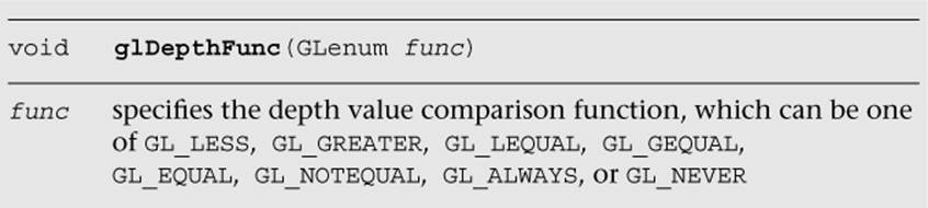
Of course, that’s only one way to use the depth buffer. You can modify the depth comparison operator by calling glDepthFunc.
Blending
This section discusses blending pixel colors. Once a fragment passes all of the enabled fragment tests, its color can be combined with the color that’s already present in the fragment’s pixel location. Before the two colors are combined, they’re multiplied by a scaling factor and combined using the specified blending operator. The blending equation is
C final = f source C source op fdestination C destination
where fsource and Csource are the incoming fragment’s scaling factor and color, respectively. Likewise, fdestination and Cdestination are the pixel’s scaling factor and color, and op is the mathematical operator for combining the scaled values.
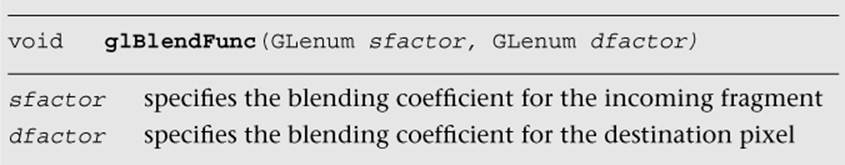
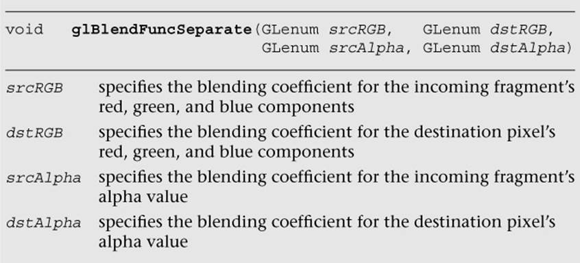
The scaling factors are specified by calling either glBlendFunc or glBlendFuncSeparate.
The possible values for the blending coefficients are shown in Table 11-3.
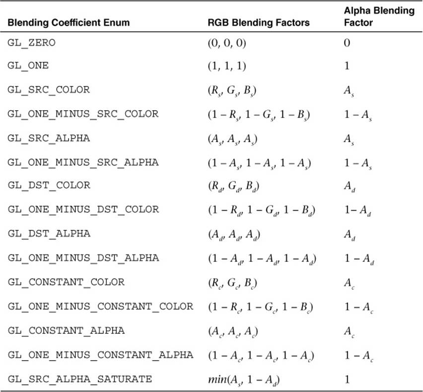
Table 11-3 Blending Functions
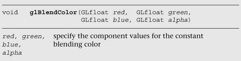
In Table 11-3, (Rs, Gs, Bs, As) are the color components associated with the incoming fragment color, (Rd, Gd, Bd, Ad) are the components associated with the pixel color already in the color buffer, and (Ra, Gc, Bc, Ac) represent a constant color that you set by calling glBlendColor. In the case of GL_SRC_ALHPA_SATURATE, the minimum value computed is applied to the source color only.
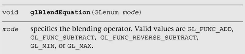
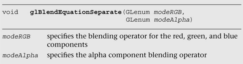
Once the incoming fragment and pixel color have been multiplied by their respective scaling factors, they are combined using the operator specified by glBlendEquation or glBlendEquationSeparate. By default, blended colors are accumulated using the GL_FUNC_ADDoperator. The GL_FUNC_SUBTRACT operator subtracts the scaled color from the framebuffer from the incoming fragment’s value. Likewise, the GL_FUNC_REVERSE_SUBTRACT operator reverses the blending equation, such that the incoming fragment colors are subtracted from the current pixel value.
Dithering
On a system where the number of colors available in the framebuffer is limited due to the number of bits per component in the framebuffer, we can simulate greater color depth using dithering. Dithering algorithms arrange colors in such a way that the image appears to have more available colors than are really present. OpenGL ES 3.0 doesn’t specify which dithering algorithm is to be used in supporting its dithering stage; the technique is very implementation dependent.
The only control your application has over dithering is whether it is applied to the final pixels. This decision is entirely controlled by calling glEnable or glDisable with GL_DITHER to specify dithering’s use in the pipeline. Initially, dithering is enabled.
Multisampled Anti-Aliasing
Anti-aliasing is an important technique for improving the quality of generated images by trying to reduce the visual artifacts of rendering into discrete pixels. The geometric primitives that OpenGL ES 3.0 renders are rasterized onto a grid, and their edges may become deformed in thatprocess. You have almost certainly seen the staircase effect that happens to lines drawn diagonally across a monitor.
Various techniques can be used to reduce those aliasing effects, and OpenGL ES 3.0 supports a variant called multisampling. Multisampling divides every pixel into a set of samples, each of which is treated like a “mini-pixel” during rasterization. That is, when a geometric primitive is rendered, it’s like rendering into a framebuffer that has many more pixels than the real display surface. Each sample has its own color, depth, and stencil value, and those values are preserved until the image is ready for display. When it’s time to compose the final image, the samples areresolved into the final pixel color. What makes this process special is that in addition to using every sample’s color information, OpenGL ES 3.0 has even more information about how many samples for a particular pixel were occupied during rasterization. Each sample for a pixel is assigned a bit in the sample coverage mask. Using that coverage mask, we can control how the final pixels are resolved. Every rendering surface created for an OpenGL ES 3.0 application will be configured for multisampling, even if only a single sample per pixel is available. Unlike in supersampling, the fragment shader is executed per pixel rather than per sample.
Multisampling has multiple options that can be turned on and off (using glEnable and glDisable, respectively) to control the usage of sample coverage value.
First, you can specify that the sample’s alpha value should be used to determine the coverage value by enabling GL_SAMPLE_ALPHA_TO_COVERAGE. In this mode, if the geometric primitive covers a sample, the alpha value of incoming fragment is used to determine an additional sample coverage mask computed that is bit-wise anded into the coverage mask that is computed using the samples of the fragment. This newly computed coverage value replaces the original one generated directly from the sample coverage calculation. These sample computations are implementation dependent.
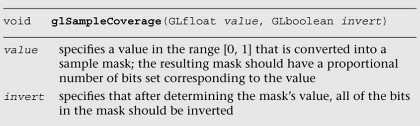
Additionally, you can specify GL_SAMPLE_COVERAGE or GL_SAMPLE_COVERAGE_INVERT, which uses the fragment’s (potentially modified by previous operations) coverage value or its inverted bits, respectively, and computes the bit-wise and of that value with one specified using theglSampleCoverage function. The value specified with glSampleCoverage is used to generate an implementation-specific coverage mask, and includes an inversion flag, invert, that inverts the bits in the generated mask. Using this inversion flag, it becomes possible to create two transparency masks that don’t use entirely distinct sets of samples.
Centroid Sampling
When rendering with multisampling, the fragment data is picked from a sample that is closest to a pixel center. This can lead to rendering artifacts near triangle edges, as the pixel center may sometimes fall outside of the triangle. In such case, the fragment data can be extrapolated to a point outside of the triangle. Centroid sampling solves this problem by ensuring that the fragment data is picked from a sample that falls inside the triangle.
To enable centroid sampling, you can declare the output variables of the vertex shader (and input variables to the fragment shader) with the centroid qualifier as follows:
smooth centroid out vec3 v_color;
Note that using centroid sampling can lead to less accurate derivatives for pixels near the triangle edges.
Reading and Writing Pixels to the Framebuffer
If you want to preserve your rendered image for posterity’s sake, you can read the pixel values back from the color buffer, but not from the depth or stencil buffers. When you call glReadPixels, the pixels in the color buffer are returned to your application in an array that has been previously allocated.
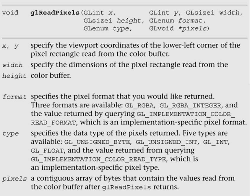
Aside from the fixed format (GL_RGBA and GL_RGBA_INTEGER) and type (GL_UNSIGNED_BYTE, GL_UNSIGNED_INT, GL_INT, and GL_FLOAT), notice that there are implementation-dependent values that should return the best format and type combination for the implementation you’re using. The implementation-specific values can be queried as follows:
GLint readType, readFormat;
GLubyte *pixels;
glGetIntegerv ( GL_IMPLEMENTATION_COLOR_READ_TYPE, &readType );
glGetIntegerv ( GL_IMPLEMENTATION_COLOR_READ_FORMAT,
&readFormat );
unsigned int bytesPerPixel = 0;
switch ( readType )
{
case GL_UNSIGNED_BYTE:
case GL_BYTE:
switch ( readFormat )
{
case GL_RGBA:
bytesPerPixel = 4;
break;
case GL_RGB:
case GL_RGB_INTEGER:
bytesPerPixel = 3;
break;
case GL_RG:
case GL_RG_INTEGER:
case GL_LUMINANCE_ALPHA:
bytesPerPixel = 2;
break;
case GL_RED:
case GL_RED_INTEGER:
case GL_ALPHA:
case GL_LUMINANCE:
case GL_LUMINANCE_ALPHA:
bytesPerPixel = 1;
break;
default:
// Undetected format/error
break;
}
break;
case GL_FLOAT:
case GL_UNSIGNED_INT:
case GL_INT:
switch ( readFormat )
{
case GL_RGBA:
case GL_RGBA_INTEGER:
bytesPerPixel = 16;
break;
case GL_RGB:
case GL_RGB_INTEGER:
bytesPerPixel = 12;
break;
case GL_RG:
case GL_RG_INTEGER:
bytesPerPixel = 8;
break;
case GL_RED:
case GL_RED_INTEGER:
case GL_DEPTH_COMPONENT:
bytesPerPixel = 4;
break;
default:
// Undetected format/error
break;
}
break;
case GL_HALF_FLOAT:
case GL_UNSIGNED_SHORT:
case GL_SHORT:
switch ( readFormat )
{
case GL_RGBA:
case GL_RGBA_INTEGER:
bytesPerPixel = 8;
break;
case GL_RGB:
case GL_RGB_INTEGER:
bytesPerPixel = 6;
break;
case GL_RG:
case GL_RG_INTEGER:
bytesPerPixel = 4;
break;
case GL_RED:
case GL_RED_INTEGER:
bytesPerPixel = 2;
break;
default:
// Undetected format/error
break;
}
break;
case GL_FLOAT_32_UNSIGNED_INT_24_8_REV: // GL_DEPTH_STENCIL
bytesPerPixel = 8;
break;
// GL_RGBA, GL_RGBA_INTEGER format
case GL_UNSIGNED_INT_2_10_10_10_REV:
case GL_UNSIGNED_INT_10F_11F_11F_REV: // GL_RGB format
case GL_UNSIGNED_INT_5_9_9_9_REV: // GL_RGB format
case GL_UNSIGNED_INT_24_8: // GL_DEPTH_STENCIL format
bytesPerPixel = 4;
break;
case GL_UNSIGNED_SHORT_4_4_4_4: // GL_RGBA format
case GL_UNSIGNED_SHORT_5_5_5_1: // GL_RGBA format
case GL_UNSIGNED_SHORT_5_6_5: // GL_RGB format
bytesPerPixel = 2;
break;
default:
// Undetected type/error
}
pixels = ( GLubyte* ) malloc( width * height * bytesPerPixel );
glReadPixels ( 0, 0, windowWidth, windowHeight, readFormat,
readType, pixels );
You can read pixels from any currently bound framebuffer, whether it’s one allocated by the windowing system or from a framebuffer object. Because each buffer can have a different layout, you’ll probably need to query the type and format for each buffer you want to read.
OpenGL ES 3.0 provides an efficient mechanism to copy a rectangular block of pixels into the framebuffer, which will be described in Chapter 12, “Framebuffer Objects.”
Pixel Pack Buffer Objects
When a non-zero buffer object is bound to the GL_PIXEL_PACK_BUFFER using glBindBuffer, the glReadPixels command can return immediately and invoke DMA transfer to read pixels from the framebuffer and write the data into the pixel buffer object (PBO).
To keep the CPU busy, you can schedule some CPU processing after the glReadPixels call to overlap CPU computations and the DMA transfer. Depending on the applications, the data may not be available immediately; in such cases, you can use multiple PBO solutions so that while the CPU is waiting for the data transfer from one PBO, it can process the data from an earlier transfer from another PBO.
Multiple Render Targets
Multiple render targets (MRTs) allow the application to render to several color buffers at one time. With multiple render targets, the fragment shader outputs several colors (which can be used to store RGBA colors, normals, depths, or texture coordinates), one for each attached color buffer. MRTs are used in many advanced rendering algorithms, such as deferred shading and fast ambient occlusion approximation (SSAO).
In deferred shading, lighting calculations are performed only once per pixel. This is achieved by separating the geometry and lighting calculations into two separate rendering passes. The first geometry pass outputs multiple attributes (such as position, normal, material color, or texture coordinates) into multiple buffers (using MRTs). The second lighting pass performs the lighting calculations by sampling the attributes from each buffer created in the first pass. As the depth testing has been performed on the first pass, we will perform only one lighting calculation per pixel.
The following steps show how to set up MRTs:
1. Initialize framebuffer objects (FBOs) using glGenFramebuffers and glBindFramebuffer commands (described in more detail in Chapter 12, “Framebuffer Objects”) as shown here:
glGenFramebuffers ( 1, &fbo );
glBindFramebuffer ( GL_FRAMEBUFFER, fbo );
2. Initialize textures using glGenTextures and glBindTexture commands (described in more detail in Chapter 9, “Texturing”) as shown here:
glBindTexture ( GL_TEXTURE_2D, textureId );
glTexImage2D ( GL_TEXTURE_2D, 0, GL_RGBA,
textureWidth, textureHeight,
0, GL_RGBA, GL_UNSIGNED_BYTE, NULL );
// Set the filtering mode
glTexParameteri ( GL_TEXTURE_2D, GL_TEXTURE_MIN_FILTER,
GL_NEAREST );
glTexParameteri ( GL_TEXTURE_2D, GL_TEXTURE_MAG_FILTER,
GL_NEAREST );
3. Bind relevant textures to the FBO using glFramebufferTexture2D or glFramebufferTextureLayer command (described in more detail in Chapter 12) as shown here:
glFramebufferTexture2D ( GL_DRAW_FRAMEBUFFER,
GL_COLOR_ATTACHMENT0,
GL_TEXTURE_2D,
textureId, 0 );
4. Specify color attachments for rendering using the following glDrawBuffers command:
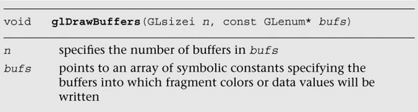
For example, you can set up a FBO with four color outputs (attachments) as follows:
const GLenum attachments[4] = { GL_COLOR_ATTACHMENT0,
GL_COLOR_ATTACHMENT1,
GL_COLOR_ATTACHMENT2,
GL_COLOR_ATTACHMENT3 };
glDrawBuffers ( 4, attachments );
You can query the maximum number of color attachments by calling glGetIntegerv with the symbolic constant GL_MAX_COLOR_ATTACHMENTS. The minimum number of color attachments supported by all OpenGL 3.0 implementations is 4.
5. Declare and use multiple shader outputs in the fragment shader. For example, the following declaration will copy fragment shader outputs fragData0 to fragData3 to draw buffers 0–3, respectively:
layout(location = 0) out vec4 fragData0;
layout(location = 1) out vec4 fragData1;
layout(location = 2) out vec4 fragData2;
layout(location = 3) out vec4 fragData3;
Putting everything together, Example 11-1 (as part of the Chapter_11/MRTs example) illustrates how to set up four draw buffers for a single framebuffer object.
Example 11-1 Setting up Multiple Render Targets
int InitFBO ( ESContext *esContext)
{
UserData *userData = esContext−>userData;
int i;
GLint defaultFramebuffer = 0;
const GLenum attachments[4] =
{
GL_COLOR_ATTACHMENT0,
GL_COLOR_ATTACHMENT1,
GL_COLOR_ATTACHMENT2,
GL_COLOR_ATTACHMENT3
};
glGetIntegerv ( GL_FRAMEBUFFER_BINDING, &defaultFramebuffer );
// Set up fbo
glGenFramebuffers ( 1, &userData−>fbo );
glBindFramebuffer ( GL_FRAMEBUFFER, userData−>fbo );
// Set up four output buffers and attach to fbo
userData−>textureHeight = userData−>textureWidth = 400;
glGenTextures ( 4, &userData−>colorTexId[0] );
for (i = 0; i < 4; ++i)
{
glBindTexture ( GL_TEXTURE_2D, userData−>colorTexId[i] );
glTexImage2D ( GL_TEXTURE_2D, 0, GL_RGBA,
userData−>textureWidth,
userData−>textureHeight,
0, GL_RGBA, GL_UNSIGNED_BYTE, NULL );
// Set the filtering mode
glTexParameteri ( GL_TEXTURE_2D, GL_TEXTURE_MIN_FILTER,
GL_NEAREST );
glTexParameteri ( GL_TEXTURE_2D, GL_TEXTURE_MAG_FILTER,
GL_NEAREST );
glFramebufferTexture2D ( GL_DRAW_FRAMEBUFFER,
attachments[i],
GL_TEXTURE_2D,
userData−>colorTexId[i], 0 );
}
glDrawBuffers ( 4, attachments );
if ( GL_FRAMEBUFFER_COMPLETE !=
glCheckFramebufferStatus ( GL_FRAMEBUFFER ) )
{
return FALSE;
}
// Restore the original framebuffer
glBindFramebuffer ( GL_FRAMEBUFFER, defaultFramebuffer );
return TRUE;
}
Example 11-2 (as part of the Chapter_11/MRTs example) illustrates how to output four colors per fragment in a fragment shader.
Example 11-2 Fragment Shader with Multiple Render Targets
#version 300 es
precision mediump float;
layout(location = 0) out vec4 fragData0;
layout(location = 1) out vec4 fragData1;
layout(location = 2) out vec4 fragData2;
layout(location = 3) out vec4 fragData3;
void main()
{
// first buffer will contain red color
fragData0 = vec4 ( 1, 0, 0, 1 );
// second buffer will contain green color
fragData1 = vec4 ( 0, 1, 0, 1 );
// third buffer will contain blue color
fragData2 = vec4 ( 0, 0, 1, 1 );
// fourth buffer will contain gray color
fragData3 = vec4 ( 0.5, 0.5, 0.5, 1 );
}
Summary
In this chapter, you learned about tests and operations (scissor box testing, stencil buffer testing, depth buffer testing, multisampling, blending and dithering) that happen after the fragment shader. This is the final phase in the OpenGL ES 3.0 pipeline. In the next chapter, you will learn an efficient method for rendering to a texture or an off-screen surface using framebuffer objects.
All materials on the site are licensed Creative Commons Attribution-Sharealike 3.0 Unported CC BY-SA 3.0 & GNU Free Documentation License (GFDL)
If you are the copyright holder of any material contained on our site and intend to remove it, please contact our site administrator for approval.
© 2016-2026 All site design rights belong to S.Y.A.