Programming the Raspberry Pi: Getting Started with Python (2013)
9. Interfacing Hardware
The Raspberry Pi has a double row of pins on one side of it. These pins are called the GPIO connector (General Purpose Input/Output) and allow you to connect electronic hardware to the Pi as an alternative to using the USB port.
The maker and education communities have already started producing expansion and prototyping boards you can attach to your Pi so you can add your own electronics. This includes everything from simple temperature sensors to relays. You can even convert your Raspberry Pi into a controller for a robot.
In this chapter, we explore the various ways of connecting the Pi to electronic devices using the GPIO. We’ll use some of the first products that have become available for this purpose. Because this is a fast-moving field, it is fairly certain that new products will have come on the market since this chapter was written; therefore, check the Internet to see what is current. I have tried to choose a representative set of different approaches to interfacing hardware. Therefore, even if the exact same versions are not available, you will at least get a flavor of what is out there and how to use it.
Products to help you attach electronics to your Pi can be categorized as either expansion boards or prototyping tools. Before we look at each of these items, we will look at exactly what the GPIO connector provides us.
![]()
GPIO Pin Connections
Figure 9-1 shows the connections available on the Raspberry Pi’s GPIO connector. The pins labeled GPIO can all be used as general-purpose input/output pins. In other words, any one of them can first be set to either an input or an output. If the pin is set to be an input, you can then test to see whether the pin is set to a “1” (above about 1.7V) or a “0” (below 1.7V). Note that all the GPIO pins are 3.3V pins and connecting them to higher voltages than that could damage your Raspberry Pi.
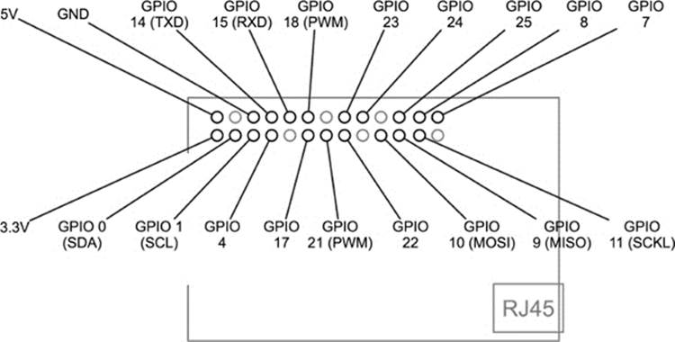
Figure 9-1 GPIO pin connections
When set to be an output, the pin can be either 0V or 3.3V (logical 0 or 1). Pins can only supply or sink a small amount of current (assume 5mA to be safe), so they can just light an LED if you use a high value resistor (say, 1kΩ). You will notice that some of the GPIO pins have other letters in parentheses after their names. Those pins have some special purpose. For example, GPIO 0 and 1 have the extra names of SDA and SCL. These are the clock and data lines, respectively, for a serial bus type called I2C that is popular for communicating with peripherals such as temperature sensors, LCD displays, and the like. This I2C bus is used by the Pi Face and Slice of PI/O discussed in the following sections.
GPIO pins 14 and 15 also double as the Rx and Tx (Receive and Transmit) pins for the Raspberry Pi’s serial port. Yet another type of serial communication is possible through GPIO 9 to 11 (MISO, MOSI, and SCLK). This type of serial interface is called SPI.
Finally, GPIO 18 and GPIO 21 are labeled PWM, meaning that they are capable of pulse width modulation. This technique allows you to control the power to motors, LEDs etc. by varying the width of pulses generated at a constant rate.
![]()
Direct Connection to GPIO Pins
With care, it is possible to attach simple electronics such as LEDs directly to the GPIO pins; however, only do this if you know what you are doing because you could easily damage your Raspberry Pi. In fact, this is more or less what we will be doing in the later section “Prototyping Boards.”
![]()
Expansion Boards
Expansion boards usually have screw terminals and a certain amount of electronics already built in. This makes them very suitable for educational use as well as for those who do not want to get deeply involved in the electronics side of things. In general, no soldering needs to be done with these kind of boards. They will usually “buffer” all the connections to the Raspberry Pi, which means the Raspberry Pi is protected from anything untoward occurring on the expansion board. For example, a short circuit across an output might damage the expansion board, but no harm will befall your precious Pi.
The sections that follow detail some of the more popular boards, explain their features, and detail how you might go about using them. One such board (the RaspiRobotBoard) will be used to create a simple robot in Chapter 11.
Pi Face
The Pi Face, shown in Figure 9-2, is a board intended primarily for educational use. It was been developed by Manchester University in the UK. As well as providing a useful hardware platform, it also provides an easy-to-use Python library and integration with the Scratch programming environment.
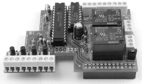
Figure 9-2 The Pi Face expansion board
The Pi Face sits on top of the Raspberry Pi and provides convenient screw terminals for connecting devices to it. It does not use the GPIO pins directly, but rather uses as an MCP23S17 port expander chip that it communicates with using the I2C serial interface. This provides eight inputs and eight outputs on the expansion board, but only the two I2C pins on the Raspberry Pi GPIO connector are used. The outputs are provided with further current amplification using a Darlington driver IC that can supply up to 500mA for each output—more than enough power to directly drive a relay or a 1W high-power LED.
Output devices on the board include two relays that can be used to switch high-load currents. Each relay also has an LED that lights when the relay is activated. There are also two LEDs that can be controlled independently. Four of the inputs have push switches next to them.
The Pi Face has its own Python module that simplifies the use of the board. The following example entered into the Python console shows you how to read digital input 2:

To turn on digital output 2, you would do the following:
![]()
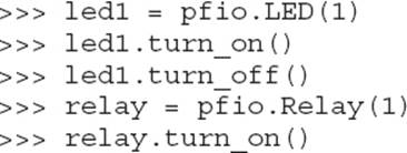
The LEDs and relays have their own control functions. The following example turns LED 1 on then off again and then turns Relay 1 on:
The library must be downloaded and installed. For downloads, documentation, and some sample projects, visit the projects code page at https://github.com/thomasmacpherson/piface. You can also find more information about the project at http://pi.cs.man.ac.uk/interface.htm.
Slice of PI/O
The Slice of PI/O, shown in Figure 9-3, is a small, low-cost board that provides eight buffered inputs and eight buffered outputs using the same MCP23S17 port expander as the Pi Face. It does not, however, have the Darlington driver of the Pi Face and, therefore, cannot drive high-power loads. The maximum load directly from the MCP23S17 is 25mA, which is enough to drive an LED with suitable series resistor, but not enough to drive a relay directly.
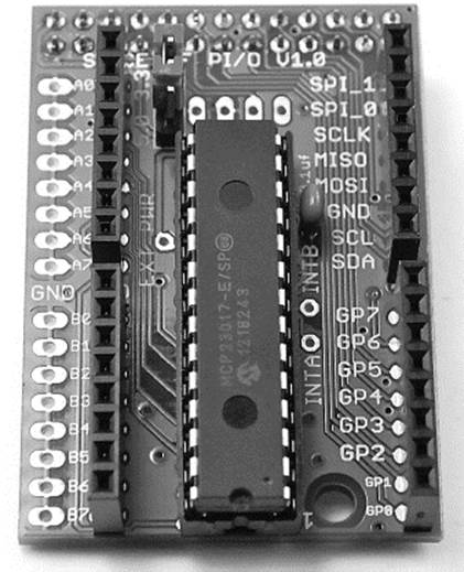
Figure 9-3 The Slice of PI/O
The board takes all the I/O pins to edge connectors, and each of the 16 I/O pins can be configured as either an input or output.
Here’s a list of the key features:
• Sixteen bidirectional buffered I/O connections
• Jumper-selected 3.3V or 5V operation
• Raspberry Pi I2C and SPI serial connections broken out (caution: unbuffered)
• Raspberry Pi GPIO pins 0 to 7 broken out (caution: unbuffered)
At the time of writing, the board is not supplied with any supporting Python module; however, this is likely to change, either through efforts of the supplier or the Raspberry Pi community.
RaspiRobotBoard
I have to declare my personal interest in the RaspiRobotBoard, shown in Figure 9-4, because it is a board I have designed. The focus of this board is firmly on allowing the Raspberry Pi to be used as a robot controller. For this reason, it has a motor controller that allows you to control the direction of two motors (usually attached to wheels).
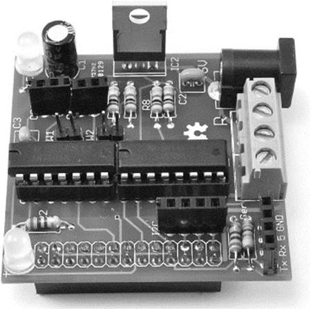
Figure 9-4 The RaspiRobotBoard
Another feature that makes it suitable for use as a robot platform is the voltage regulator that powers the Raspberry Pi using any source of power between 6V and 9V, such as four AA batteries. The RaspiRobotBoard also has connectors for two different types of serial port, one of which is intended to take an adapter board for an ultrasonic range finder module. The board also has a pair of switch inputs, two LEDs, and another pair of buffered outputs that can be used to drive other LEDs or low-current loads. This board is used in Chapter 11 to build a small roving robot.
Gertboard
The Gertboard is designed by Gert van Loo of Broadcom and therefore is the most official Raspberry Pi expansion board (see Figure 9-5).
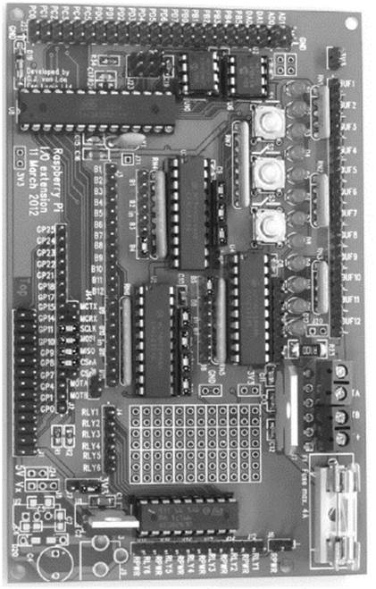
Figure 9-5 A Gertboard expansion board for the Pi
The Gertboard is really the kitchen sink of expansion boards. Its key features are as follows:
• Strapping area where GPIO pins can be connected to different modules
• ATmega (like the Arduino) microcontroller
• SPI analog-to-digital and digital-to-analog converters
• Motor controller (like the RaspiRobotBoard)
• 500mA open collector outputs (like the Pi Face)
• Twelve LEDs and three push buttons
![]()
Prototyping Boards
Unlike expansion boards, prototyping boards mostly require the use of a soldering iron and a certain amount of electronics expertise. They also connect directly to the Raspberry Pi’s main chip, which means that if you get it wrong, you could easily damage your Raspberry Pi. These boards are for the experienced electronics enthusiast—or the very careful or the very reckless (who doesn’t mind the possibility of killing their Raspberry Pi).
One of these prototyping boards, the “Cobbler,” is not actually a board but rather a connector that allows you to link the GPIO connections to a solderless breadboard where you can add your own electronics. As a contrast to the expansion board approach, we will explore this method further in the next chapter using the Cobbler.
Pi Cobbler
The Pi Cobbler from Adafruit (www.adafruit.com/products/914) comes as a kit that must be soldered together. The soldering is pretty straightforward, and once everything is assembled, you will have a board with 26 pins coming out of the bottom that can be attached to a solderless breadboard (see Figure 9-6). On top of the board is a 26-pin socket to which a 26-way ribbon cable lead (also supplied) can be used to link the Raspberry Pi GPIO connector to the Cobbler.
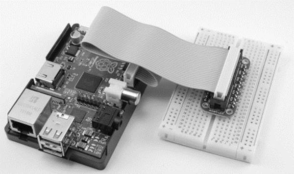
Figure 9-6 The Adafruit Pi Cobbler
Pi Plate
The Pi Plate, shown in Figure 9-7, is another product from Adafruit (https://www.adafruit.com/products/801). This is a prototyping board that has a large area in the middle to which you can solder the components for your project. Screw terminals are located all around the edge of the board so you can attach leads to external components that won’t fit on the board, such as motors and such. In one corner of the board is an area to which a surface mount IC can be soldered. The pins next to it “break out” the difficult-to-use pins of the IC.
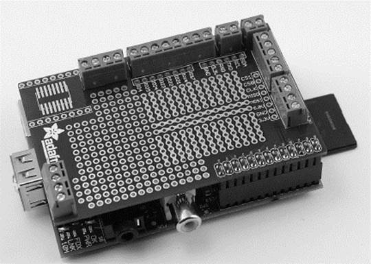
Figure 9-7 The Adafruit Pi Plate
Humble Pi
The Humble Pi, shown in Figure 9-8, is quite similar to the Pi Plate, but it lacks the surface mount prototyping area. However, it makes up for this by providing an area where you can add your own voltage regulator and power socket, making it suitable for powering the Pi at 5V from batteries or an external power supply. No voltage regulator or associated capacitors are provided, although Ciseco sells a kit of components for this.
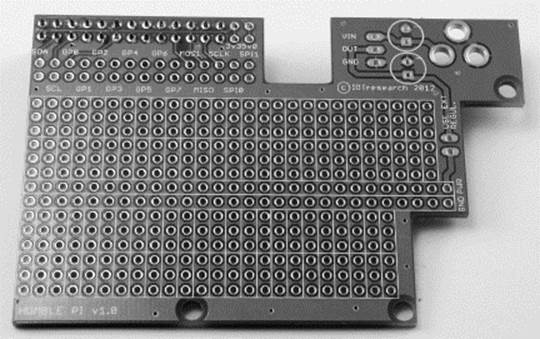
Figure 9-8 The Humble Pi
![]()
Arduino and the Pi
Although the Raspberry Pi can be used like a microcontroller to drive motors and such, this is not really what it was designed for. As such, the GPIO pins cannot supply much in the way of drive current and are somewhat delicate and intolerant of electrical abuse. This is, after all, the motivation for the expansion boards described in the previous section.
Arduino boards, on the other hand, are much more rugged and designed to be used to control electronic devices (see Figure 9-9). What is more, they have analog inputs that can measure a voltage from, say, a temperature sensor.
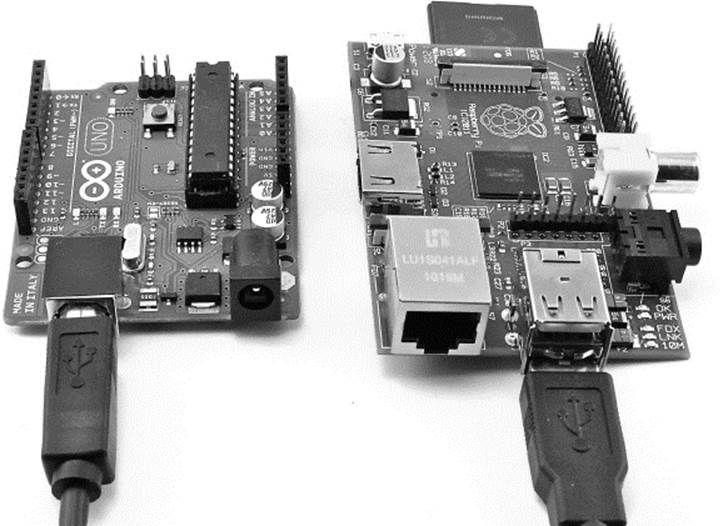
Figure 9-9 An Arduino board connected to a Raspberry Pi
Arduino boards are designed to allow communication with a host computer using USB, and there is no reason why this host shouldn’t be a Raspberry Pi. This means that the Arduino takes care of all the electronics and the Raspberry Pi sends it commands or listens for incoming requests from the Arduino.
If you have an Arduino, you can try out the following simple example, which allows you to send messages to the Arduino to blink its build-in LED on and off while at the same time receiving incoming messages from the Arduino. Once you can do that, it is easy to adapt either the Arduino sketch or the Python program on the Raspberry Pi to carry out more complex tasks.
This example assumes you are familiar with the Arduino. If you are not, you may want to read some of my other books on the Arduino, including Programming Arduino: Getting Started with Sketches and 30 Arduino Projects for the Evil Genius.
Arduino and Pi Talk
To get the Arduino and Pi to talk, we are going to connect them using a USB port on the Raspberry Pi. Because the Arduino only draws about 50mA and in this case has no external electronics attached to it, it can be powered by the Pi.
The Arduino Software
All you need to do is load the following Arduino sketch onto the Arduino. You will probably want to do this with your regular computer, because at the time of writing, only a very old version of the Arduino software is available for the Raspberry Pi. The following sketch is available in the downloads package and is called PiTest.ino:
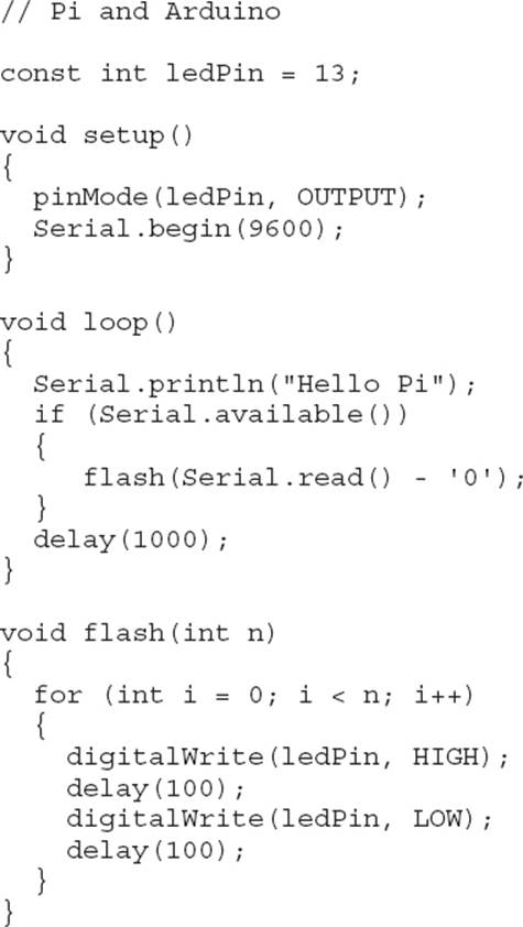
This very simple sketch contains just three functions. The setup function initializes serial communications and sets pin 13 on the LED to be an output. This pin is attached to the LED built into the Arduino. The loop function is invoked repeatedly until the Arduino is powered down. It first sends the message “Hello Pi” to the Raspberry Pi and then checks to see whether there is any incoming communication from the Pi. If there is (it expects a single digit), it flashes the LED on and off that many times using the flash function.
The Raspberry Pi Software
The Python code to talk to the Arduino is even more simple and can just be typed into the Python console. But first, you need to install the PySerial package to allow the communication to take place. This is done in the same way as the other packages we have installed—just fetch the zipped tar file from http://sourceforge.net/projects/pyserial/files/latest/download?source=files.
Next, extract the directory from the archive by entering the following command:
![]()
Now that you have a new folder for the module, just cd into it and then run the install command (first, though, it is worth checking the instructions to see if anything else needs doing beforehand). You are now ready to run the module installer itself, as follows:
![]()
Once it’s installed, you will be able to import the module from the Python shell. Now switch from the Linux terminal to a Python console and type the following:

This opens the USB serial connection with the Arduino at the same baud rate of 9600. Now you need to start a loop listening for messages from the Arduino:
![]()
You will need two hit ENTER twice after you type the second line. Messages should now start to appear! You can see in the blue writing where the Arduino is talking to the Pi and then some error trace as you press CTRL-C to interrupt the messages coming from the Arduino.
Now type the following into the Python console:
![]()
This should cause the LED to flash five times.
![]()
Summary
In this chapter we looked at just some of the wide range of ways of adding electronics to our Raspberry Pi projects. In the next two chapters, we create projects using two different approaches—first using the Adafruit Cobbler and breadboard and then using the RaspiRobotBoard as the basis for a small roving robot.
All materials on the site are licensed Creative Commons Attribution-Sharealike 3.0 Unported CC BY-SA 3.0 & GNU Free Documentation License (GFDL)
If you are the copyright holder of any material contained on our site and intend to remove it, please contact our site administrator for approval.
© 2016-2026 All site design rights belong to S.Y.A.