Learn to Program with Scratch: A Visual Introduction to Programming with Games, Art, Science, and Math (2014)
Chapter 4. Procedures
This chapter explains how you can take a “divide and conquer” approach to programming. Rather than build your programs as one big piece, you’ll be able to write separate procedures that you then put together. Using procedures will make your programs both easier to write and easier to test and debug. In this chapter, you’ll learn how to:
§ Use message broadcasting to coordinate the behavior of many sprites
§ Use message broadcasting to implement procedures
§ Use the “build your own block” feature of Scratch 2
§ Use structured programming techniques
Most of the applications we’ve developed so far contain only one sprite, but most applications require multiple sprites that work together. An animated story, for example, might have several characters as well as different backgrounds. We need a way to synchronize the sprites’ assigned jobs.
In this chapter, we’ll use Scratch’s message-broadcasting mechanism to coordinate work among several sprites (this was the only way to implement procedures in the previous version of Scratch). We’ll then discuss how to use Scratch 2’s “custom blocks” feature to structure large programs as smaller, more manageable pieces called procedures. A procedure is a sequence of commands that performs a specific function. For example, we can create procedures that cause sprites to draw shapes, perform complex computations, process user input, sequence musical notes, manage games, and do many other things. Once created, these procedures can serve as building blocks for constructing all sorts of useful applications.
Message Broadcasting and Receiving
So how does the broadcast system in Scratch work in practice? Any sprite can broadcast a message (you can call this message anything you like) using the broadcast or broadcast and wait blocks (from the Events palette) shown in Figure 4-1. This broadcast triggers all scripts in all sprites (including the broadcasting sprite itself) that begin with a matching when I receive trigger block. All sprites hear the broadcast, but they’ll only act on it if they have a corresponding when I receive block.
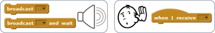
Figure 4-1. You can use the message-broadcasting and receiving blocks to coordinate the work of multiple sprites.
Consider Figure 4-2. It shows four sprites: starfish, cat, frog, and bat. The starfish broadcasts the jump message, and that broadcast is sent to all sprites, including itself. In response to this message, both the cat and the frog will execute their jump scripts. Notice how each sprite jumps in its own way, executing a different script. The bat also receives the jump message, but it does not act on it because it was not told what to do when it receives this message. The cat in this figure knows how to walk and jump, the frog can only jump, and the bat was taught only to fly.
The broadcast and wait command works like the broadcast command, but it waits until all message recipients have finished executing their corresponding when I receive blocks before continuing.
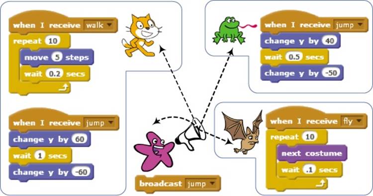
Figure 4-2. A broadcast message is received by all sprites, even by the sprite that sent the broadcast.
Sending and Receiving Broadcasts
SquareApp.sb2
To demonstrate how message broadcasting and receiving work, let’s create a simple application that draws randomly colored squares. When the user clicks the left mouse button on the Stage, the Stage will detect this event (using its when this sprite clicked block) and broadcast a message that you’ll call Square (you can choose a different name if you want). When the only sprite in this application receives this message, it will move to the current mouse position and draw a square. Follow these steps to create the application:
1. Start Scratch and then select New from the File menu to start a new application. Feel free to change the cat’s costume to anything you like.
2. Add the when I receive block (from the Events palette) to the Scripts Area of the sprite. Click the down arrow in this block and select new message... from the drop-down menu. In the dialog that appears, type Square and click OK. The name of the block should change to when I receive Square.
3. Complete the script as shown in Figure 4-3. The sprite first lifts its pen and moves to the current mouse position, indicated by the mouse x and mouse y blocks (from the Sensing palette). It then picks a random pen color, lowers its pen, and draws a square.
The sprite is now ready to handle the Square message when it is received. The script in Figure 4-3 can be called a message handler since its job is to handle (or process) a broadcast message.
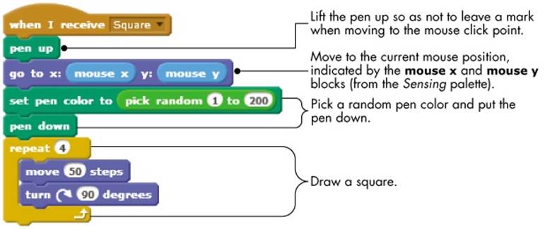
Figure 4-3. The Square message handler
Now, let’s go to the Stage and add the code to broadcast the Square message in response to a mouse click. Click the Stage in the Sprite List and add the two scripts shown in Figure 4-4. The first script clears any pen marks from the Stage when the green flag is clicked. The second script, which is triggered when the user clicks the mouse on the Stage, uses the broadcast block to tell the sprite that it is time to draw.
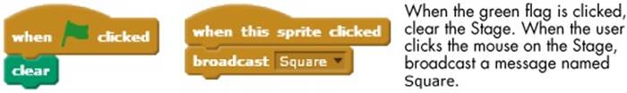
Figure 4-4. The two scripts for the Stage in the Square drawing application
The application is now complete. To test it, just click the mouse on the Stage. It should respond by drawing a square in response to each mouse click.
Message Broadcasting to Coordinate Multiple Sprites
Flowers.sb2
To see multiple sprites respond to the same broadcast message, let’s create an application that draws several flowers on the Stage in response to a mouse click. The Flowers application contains five sprites (named Flower1 through Flower5) that are responsible for drawing five flowers on the Stage. Each sprite has its own costume, as shown in Figure 4-5. Note how the background of each costume is transparent. Note also the location of the center of rotation for each costume (marked with the crossed lines).
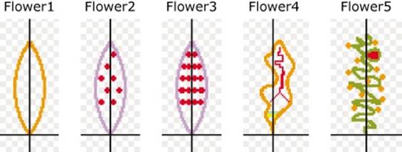
Figure 4-5. Flowers uses these five petal sprites (as shown in the Paint Editor).
When a sprite receives a message to draw its flower, it will stamp multiple rotated copies of its costume on the Stage, as illustrated in Figure 4-6. The figure also shows sample outputs from the flower-drawing script we’ll explore next.
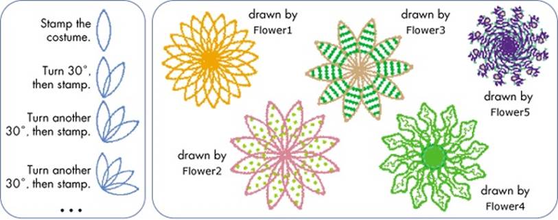
Figure 4-6. The Flowers application’s drawing process (left) and some possible flowers (right)
When you click the mouse on the Stage, the Stage detects the mouse click using the when this sprite clicked block. In response, it clears its background and broadcasts a message called Draw. All five sprites respond to this message by executing a script similar to the one shown in Figure 4-7.
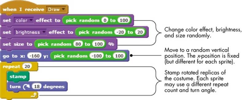
Figure 4-7. The basic script used by each of the five sprites
The script starts by assigning random values to the color effect, brightness effect, and size to change the appearance of the drawn flower. It then moves to a random vertical position on the Stage and draws a flower by stamping rotated replicas of its costume.
Open this application (named Flowers.sb2) and run it to see how it works. Despite its simplicity, its output is intriguing. I encourage you to design different costumes to create different types of flowers. Change the costumes’ centers to discover even more interesting flower designs.
Now that you understand how message broadcasting and receiving work, we’ll move on to introduce structured programming as a way to manage the complexity of large programs.
Creating Large Programs in Small Steps
The scripts that you’ve written up to this point are relatively short and simple. Eventually, you’ll write longer, more complex scripts that contain hundreds of blocks, and understanding and maintaining them will become a real challenge.
An approach known as structured programming was developed in the mid-1960s to simplify the process of writing, understanding, and maintaining computer programs. Instead of having you write a single large program, this approach calls for dividing the program into smaller pieces, each of which solves one part of the overall task.
Consider, for example, the process of baking a cake. You may not think about the individual steps as you bake, but the process follows a precise recipe that lists the necessary steps. The recipe might include instructions like (1) mix 4 eggs, 2 oz of flour, and 1 cup of water; (2) put the mixture in a pan; (3) put the pan in the oven; (4) bake for 1 hour at 350°F; and so on. In essence, the recipe breaks down the problem of baking a cake into distinct logical steps.
Similarly, when you design a solution for your programming problem, it helps to break the problem down into manageable, “mind-sized” bites. This approach helps you maintain a clear view of the whole program and the relationships between its component parts.
Consider Figure 4-8, which shows a long script that draws a shape on the Stage. You’ll see that you can divide this script into smaller logical blocks by function. The first six blocks, for example, initialize the sprite. The first repeat block draws a square, the second draws a triangle, and so on. Using the structured programming approach, we can group related blocks together under a representative name to form procedures.
Once we write these procedures, we can call them in a certain sequence to solve our programming problem. Figure 4-8 also shows how the separate procedures are put together to achieve the same function as the original script. Clearly, the script that uses procedures (right) is more modular and easier to understand than the original (left).
Procedures can also help you avoid writing the same code twice. If a set of commands is executed in several places in a program, you can write a procedure that performs these commands and use it instead. This strategy to avoid duplicating code is referred to as code reuse. Note, for example, how the Draw square procedure was reused in Figure 4-8.
Using procedures enables you to apply the “divide-and-conquer” strategy to solve complex problems. You divide a large and complex problem into subproblems and then conquer these simpler problems individually, testing each one in isolation. After solving all the subproblems in isolation, you put these pieces together in a way that solves the original problem. This is similar to our cake-baking strategy: Our recipe divided the problem into well-defined steps, and we executed these steps in the correct order to build the final product (our cake).
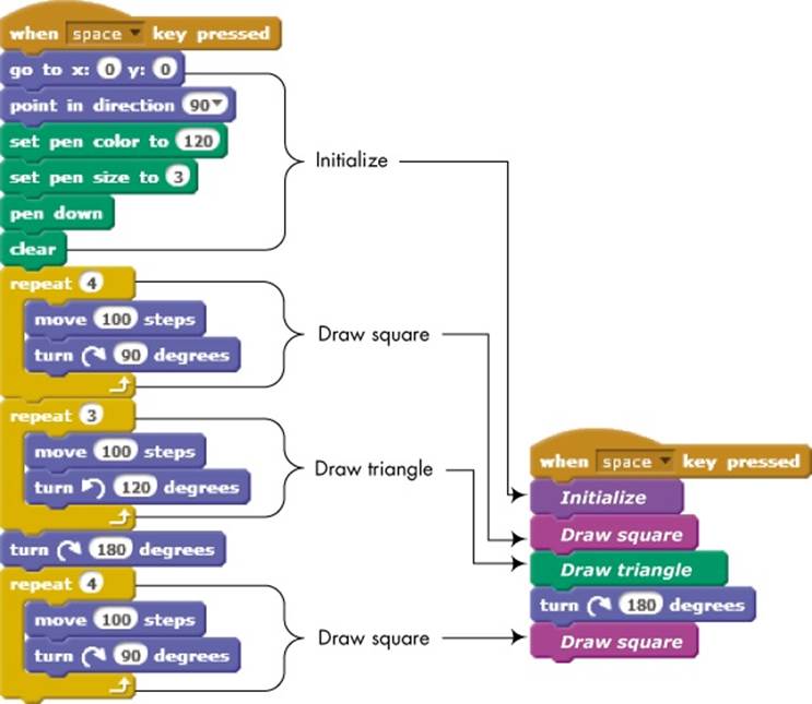
Figure 4-8. Breaking a large script into logical parts that each complete one function
At this point, you might ask, “How do we create these procedures?” Before Scratch 2, you couldn’t build the Initialize block shown in Figure 4-8 and then call it from your script. The only way to emulate procedures and add some structure to a program was through Scratch’s message-broadcasting mechanism. This has changed in Scratch 2, which added the powerful “custom blocks” feature.
In this section, we’ll demonstrate the old way of doing things, because that’s what you’ll see in scripts created in an older version of Scratch. However, the build-your-own-block feature will be explained in the next section, and it will be used consistently throughout the rest of the book.
Since sprites receive their own broadcast messages, we can implement procedures by having a sprite broadcast a message to itself and perform the desired task under the when I receive trigger block. We can use the broadcast and wait block to ensure that our procedures are called in the correct sequence, thus adding structure and modularity to our programs. Confused? Let’s see it in action.
Creating Procedures with Message Broadcasting
Flowers2.sb2
We’ll explore how procedures work and how they can improve your code by re-creating the Flowers program from earlier.
Open the file Flowers2.sb2, which contains the new version of the program. The script for the Stage is the same as before (the Stage broadcasts a Draw message when it detects a mouse click), but this time, our program uses only one sprite instead of five. This sprite has five costumes, leaf1through leaf5, and will call a procedure to draw a flower for each costume. Since we have a single sprite, we only need one copy of the drawing code (not the five duplicate scripts we had in our first version). This makes the program smaller and the code easier to understand. When the sprite in this application receives the Draw message, it executes the script shown in Figure 4-9.
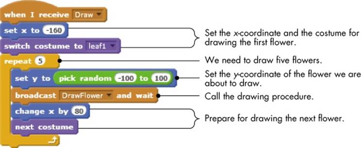
Figure 4-9. When the sprite receives the Draw message, it calls DrawFlower five times (in a loop) to draw five flowers.
The script sets the x-coordinate and the costume for drawing the first flower and then enters a loop to draw five flowers. On each pass, the loop sets the y-coordinate for the flower and calls DrawFlower by broadcasting a message to itself. This call halts the script’s execution untilDrawFlower is done. When this happens, the Draw script resumes execution, adjusting the x-coordinate and changing the costume in preparation for drawing the next flower.
NOTE
You can name a procedure anything you like, but I recommend selecting a name that reflects that procedure’s purpose. This is especially helpful when you revisit a program that you wrote months ago. For example, if you want to show players how many points they have in a game, you might create a procedure named ShowScore. Naming this procedure Mary or Alfredcertainly won’t remind you (or anyone else reading your program) what the procedure does.
The DrawFlower procedure is shown in Figure 4-10. It sets random values for the color effect, brightness, and sprite size before stamping rotated versions of the current costume to draw a flower.
While the first version of the program contained five sprites and five repeated scripts, the second version achieves the same result using a single sprite that calls one procedure for drawing all five flowers. Open Flowers.sb2 and Flowers2.sb2 in two tabs of your browser and compare them. Isn’t the new version much simpler to follow? Using procedures lets you make smaller programs that are easier to understand and maintain. This will become more beneficial as you write programs to perform more complex tasks.
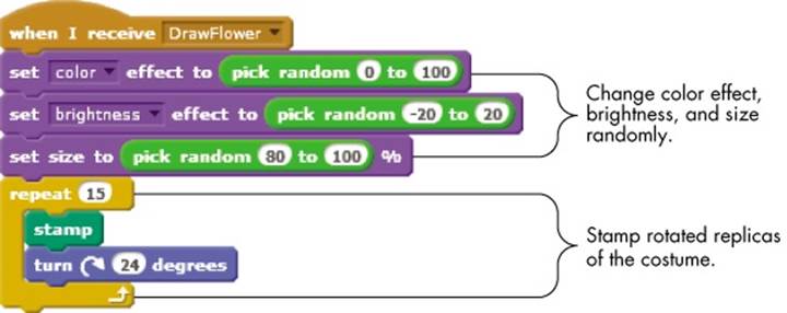
Figure 4-10. The DrawFlower procedure
Building Your Own Block
As of Scratch 2, you can also create your own custom blocks. After you make a custom block, it should appear in the More Blocks palette, where you can use it as you would any other Scratch block.
To show you how to create and use these blocks, we’ll modify the Flowers2 program we discussed in the last section to use a custom block for the DrawFlower procedure. The following steps will guide you through creating this new version of the application.
1. First, open the Flowers2.sb2 file that you looked at in the previous section. Select File ▸ Download to your computer from the File menu and save the file as Flowers3.sb2. You can pick a different name if you prefer.
2. Click the thumbnail of the Flower sprite to select it. Then select the More Blocks palette and click Make a Block. You should see the dialog shown in Figure 4-11 (left). Type DrawFlower for the block’s name and click OK. A new function block called DrawFlower should appear under the More Blocks palette, and a define DrawFlower block should appear in the Scripts Area as shown in the figure (right).
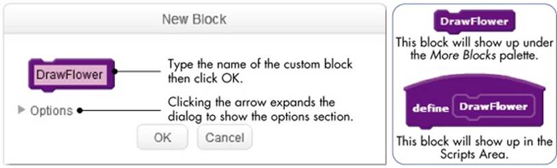
Figure 4-11. The New Block dialog and the blocks that appear after creating the DrawFlower custom block
3. Detach the script connected to the when I receive DrawFlower block and connect it to the define DrawFlower block, as shown in Figure 4-12. This results in a new procedure, called DrawFlower, that is implemented as a custom block. Delete the when I receive DrawFlower block because it is no longer needed.
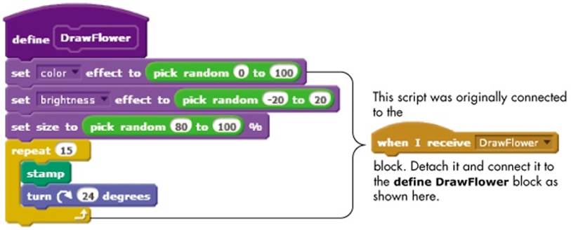
Figure 4-12. The DrawFlower procedure implemented as a custom block
4. Now that we’ve created a DrawFlower procedure, we just need to call it from the Draw message handler. Modify the Draw message handler as shown in Figure 4-13. Note that we only replaced the broadcast DrawFlower and wait block with our new DrawFlower custom block.
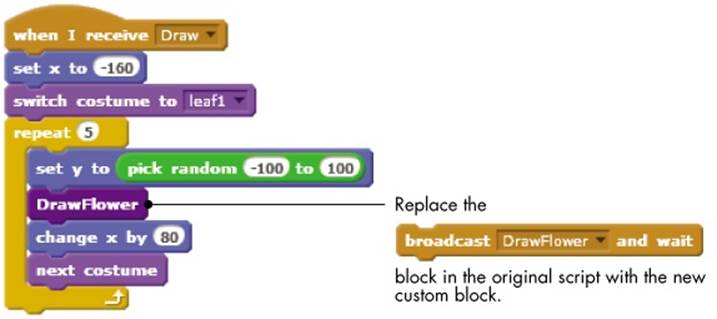
Figure 4-13. Calling DrawFlower from the Draw message handler
The program is now complete, and you can test it. Click the mouse on the Stage to verify that the program still works as before. See Running without Screen Refresh to learn how you can speed up the execution of this program.
Now that you know the basics behind custom blocks, you can take them a step further by making blocks that can accept inputs.
RUNNING WITHOUT SCREEN REFRESH
Implementing the DrawFlower procedure with custom blocks brings up another feature that can shorten the execution time of the drawing script. To demonstrate, perform the following:
1. Right-click the DrawFlower block under the More Blocks palette and select edit from the pop-up menu. This should bring up the dialog from Figure 4-11, except that the title will be Edit Block instead of New Block.
2. Click the arrow next to Options, check the Run without screen refresh box and click OK (see Figure 4-15).
3. Now, click the mouse on the Stage and see what happens. Instead of seeing the individual rotating and stamping steps as the five flowers are drawn, you should see them appear on the Stage almost at once. Here is an explanation of what’s happening.
The DrawFlower procedure contains many blocks that change a sprite’s appearance, including set color, set brightness, set size, and stamp. After executing such a block, Scratch normally pauses for a while to refresh (that is, redraw) the screen. This is why we were able to see the drawing progress when the application ran before.
If you select the Run without screen refresh option, the blocks will run without pausing to refresh the screen, allowing the procedure to run much faster. The screen will refresh after Scratch executes the entire procedure.
In addition to speeding up a procedure, the Run without screen refresh option helps to prevent the flickering that repeated redrawing can cause.
Passing Parameters to Custom Blocks
Let’s start by creating a custom block named Square, which draws a square whose side length is 100 pixels, as shown in Figure 4-14.
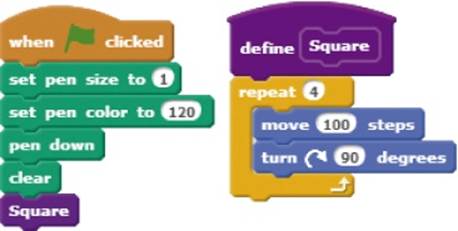
Figure 4-14. A Square procedure that draws a fixed-size square
The Square procedure has limited capabilities, because the drawn square size is fixed once and for all. What if you want to draw squares with different side lengths, such as 50, 75, or 200? You could define several custom blocks named Square50, Square75, and Square200, but creating multiple blocks that do essentially the same thing is, in most cases, a bad idea; if you need to make a change, then you have to track down all the copies and change those as well. A better solution is to have a single Square block that allows the user to specify the desired side length when calling it.
You’ve actually been applying this concept since Chapter 1. For example, Scratch provides a single move block that allows you to specify how many steps a sprite will move by entering that number in a parameter slot. That way, Scratch doesn’t have to provide a new block for every possible move distance.
What we need to do, therefore, is add a parameter slot to our Square block where the user can enter the side length. Figure 4-15 illustrates how to modify the Square block.
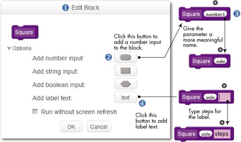
Figure 4-15. Adding a number input to the Square block
First, right-click the Square block in the More Blocks palette (or the define Square block in the Scripts Area) and select edit from the pop-up menu to bring up the Edit Block dialog ①. Click the small arrow next to Options to expand the dialog and see the available options.
We want our Square block to accept the desired side length of a square, which is a number, so click Add number input ② to add a number slot to the block. A number slot named number1 should be added to the Square block.
To indicate that the new slot is intended to carry the side length of the square, change the default name from number1 to something meaningful ③, such as side, length, or sideLength. (Again, although Scratch doesn’t care what label you use, you do! Pick a name that reflects the meaning of the parameter.) Let’s use the name side for this example.
Technically, that’s all what we need to do to add a number slot to our procedure. If we click OK, we’ll have a Square block that takes a number as input. We could drag this block into our scripts and specify the desired length in the parameter slot, as in Square 50. But how would a user know what the number passed to Square means? Does it mean an area of 50, a diagonal of 50, a side length is 50, or something else?
Imagine if Scratch’s glide block were designed like this:
![]()
How would you know that the first slot represents time (in seconds) and the second and third slots represent the x- and y-coordinates of the target glide point? The Scratch designers made the glide block easier to understand and use by adding labels to these slots as follows:
![]()
Let’s do the same thing for our Square block by adding text that describes the meaning (or usage) of the parameter slot. Click Add label text ④, as shown in Figure 4-15, to add a label after the side parameter. Type steps for the label text and click OK.
Now, if you examine the definition of the Square procedure in the Scripts Area, you’ll see a small block (named side) added to its header, as illustrated in Figure 4-16 (left). The move block still has the fixed number 100 inside it, but all we need to do now is drag the side block from the header of the Square method and drop it over the parameter slot of the move block to replace the number 100, as shown in Figure 4-16 (right).
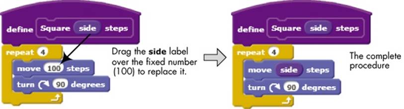
Figure 4-16. Modifying the Square procedure to use the side parameter
The label, side, that appears in the header of the Square procedure is called a parameter. You can think of a parameter as a named placeholder. We wanted our Square procedure to be able to draw squares of any size, so instead of hard-coding a fixed number inside our procedure, we used a general parameter named side. Users will specify the exact value of side when they call the Square procedure. Let’s illustrate this point by modifying the script in Figure 4-14 to use the new version of our Square procedure. The required changes are illustrated in Figure 4-17.
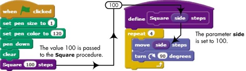
Figure 4-17. Calling the Square procedure with side set to 100
Here, the number 100 (called an argument) is passed to the Square procedure. When Square is executed, its side parameter is set to 100, and this value is used to replace all occurrences of the side block inside the procedure. As you can see, the ability to specify different arguments to a procedure is a powerful feature that adds a lot of flexibility to our programs.
We can enhance our Square procedure even further by making it accept the square’s color as a second parameter, as shown in Figure 4-18. Here, we added a second input parameter, called clrNum (short for color number), which indicates the desired color of the square. The procedure now sets the pen color to the value specified by clrNum before executing the drawing loop. Edit the Square block to implement the changes shown in the figure.
PARAMETERS VS. ARGUMENTS
Although many programmers use the terms parameter and argument inter-changeably, the two terms are in fact different. To clarify, consider the Average procedure shown below, which computes the average of two numbers.
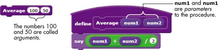
As defined, this procedure has two parameters named num1 and num2. A parameter defines an input to a procedure. You’d call this procedure with the block shown at the left and specify some values or expressions inside the available slots. The values 100 and 50 in the above example are called arguments of the procedure.
Of course, the number of arguments in the procedure call must match the number of parameters in the procedure’s definition. When you call Average, the parameters num1 and num2 receive the values 100 and 50, respectively, because arguments and parameters are matched by position.
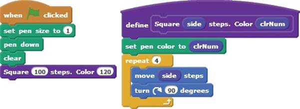
Figure 4-18. This version of Square takes the desired color as a second parameter.
TRY IT OUT 4-1
What about the thickness of the square’s border? Modify the Square procedure to take a third parameter, called penSize, that specifies the size of the pen to be used in drawing the square.
Let’s conclude this section with some useful tips for dealing with custom blocks:
§ Custom blocks can’t be shared among sprites. If you create a custom block for, let’s say, Sprite1, then only Sprite1 can use that block. Similarly, a custom block defined for the Stage can only be called by scripts that belong to the Stage.
§ Give your parameters meaningful names that indicate what they’re used for.
§ To delete a custom block, just drag its define block (that is, the hat block) from the Scripts Area and drop it over the Palettes area. You can only delete a define block if your project doesn’t contain any stack blocks associated with it, so remove all uses of a custom block from your scripts before trying to delete it.
§ To delete a parameter of a custom block, click the parameter’s name in the Edit Block dialog and then click the small X icon that appears above the parameter’s slot.
§ In addition to number inputs, you can also add string and Boolean parameters. We’ll talk more about data types when we discuss variables in the next chapter.
Now, you might wonder: Can a procedure call another procedure? In the next section, you’ll learn about how to use nested procedure calls to extend the power and usefulness of existing procedures.
Using Nested Procedures
As we noted earlier, a procedure should be designed to perform a single, well-defined task. To execute multiple tasks, it is perfectly legal—and in many cases desirable—to have one procedure call another as part of its execution path. Nesting procedures this way gives you great flexibility in structuring and organizing your programs.
RotatedSquares.sb2
To see this in action, let’s start with the Square procedure we wrote in the previous section (see Figure 4-17). Now, we’ll create a new procedure, called Squares, that draws four stretched squares, as illustrated in Figure 4-19. It does so by calling the Square procedure four times. Each call uses a different argument, and the output is four squares that share a corner.
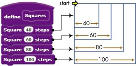
Figure 4-19. The Squares procedure and its output
We can now use Squares to create some interesting art. Figure 4-20 shows another procedure, called RotatedSquares, which calls the Squares procedure several times, turning the shapes by some angle after each call.
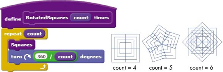
Figure 4-20. The RotatedSquares procedure and some possible outputs
In this procedure, the count parameter is used twice: once to determine the number of repetitions and again to calculate the turn angle after calling Squares. Setting count to 5, for example, will result in repeating the square pattern of Figure 4-20 five times with a 72° (that is, 360° / 5) right turn after each call. Experiment with different values to discover new patterns.
Checkers.sb2
Let’s work out another example that demonstrates the power of nested procedures: We’ll start with the Square procedure of Figure 4-16 and end up with a checkerboard.
Create a new procedure (called Row) that draws a single row of squares, as illustrated in Figure 4-21. Note that the number of squares to draw is specified as a parameter. To keep things simple, we’ve fixed the size of the individual squares at 20 steps instead of defining the size as a second parameter to the Row procedure.
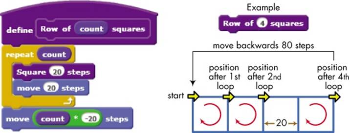
Figure 4-21. The Row procedure
Figure 4-21 also illustrates the result of calling Row with an argument of 4, which makes the procedure call Square 20 steps four times in a loop. The sprite’s position is adjusted after drawing each square to set the initial position for the next square. After drawing the four squares, the last command returns the sprite to its initial position.
To draw another row of squares below the one shown in Figure 4-21, we just need to move the sprite down 20 steps and then call the Row procedure again. We can repeat this to draw as many rows as we want. Our Checkers procedure, shown in Figure 4-22, does just that.
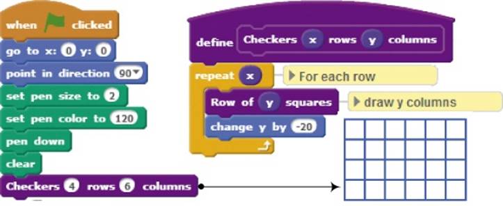
Figure 4-22. The Checkers procedure and its output
This procedure takes two parameters: the number of rows and the number of columns for the desired checkerboard. After drawing each row, the procedure moves the sprite down 20 steps to prepare to draw the next row of squares.
The examples presented in this section show how procedures can help you divide a program into smaller, more manageable pieces. Once you’ve written and tested your procedures, you can use them as building blocks for more complex procedures without worrying much about the low-level implementation details. You can then focus on the important task of putting together the whole application using these procedures as building blocks.
TRY IT OUT 4-2
What do you think will happen if you set the initial direction to 0° (up) instead of 90° (right)? Will the script work? If not, how could you fix it? Make this change and run the script to test your answer.
Working with Procedures
Now that you know why it’s important to break your program down into smaller parts and tackle them one at a time, let’s discuss how to perform this division. Every problem is different, and there is no “one size fits all” solution—but that’s what makes this a fun puzzle!
In this section, we’ll first explore the top-down process of dividing a large program into modular pieces with a clear logical structure. We’ll then discuss another way of building complex programs: the bottom-up process of combining existing procedures. Figure 4-23 shows a high-level view of these two approaches.
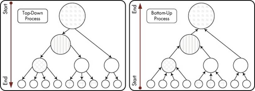
Figure 4-23. Illustrating top-down (left) and bottom-up (right) approaches
In both diagrams, the problem we want to solve is at the top, and the individual steps that build our solution are at the bottom. You can start from whichever level makes sense to you.
Breaking Programs Down into Procedures
The first step in solving any programming problem is to fully understand the problem. After that, you can plan a general solution and divide it into major tasks. There is no right or wrong way to go about dividing up any particular program, and with experience, you will get better at deciding what “major” means. Working from the general solution down to its specifics ensures that, at least, the overall logic of the program is correct.
House.sb2
To demonstrate this problem-solving strategy, let’s consider how we would draw a house similar to that shown in Figure 4-24.
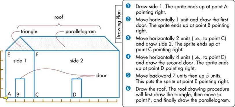
Figure 4-24. We can draw this house by dividing the task into several smaller pieces and handling each piece individually.
On one hand, working on this simple problem allows us to focus on the solution strategy without getting bogged down in a lot of detail. On the other hand, despite its apparent simplicity, the problem lends itself to many different solutions. Here are some possibilities:
§ We can view the house as made up of straight lines. In this case, drawing each line is a major task.
§ We can view the house as made up of six independent shapes: side 1, side 2, two doors, a triangle, and a parallelogram. Drawing each shape constitutes a major task.
§ Since the two doors are identical, we can define one major task for drawing a door and invoke that task twice.
§ We can view the triangle and the parallelogram at the top of the house as one unit, the roof. In this case, one major task is to draw the roof.
§ We can view side 1 and its door as one unit, the front side. In this case, one major task is to draw the front side.
There are many other possibilities, but that’s enough to illustrate the point. The idea is to group tasks into small, understandable pieces that you can deal with and then focus on one piece at a time. If you find similar pieces, try to come up with a common solution and apply it to all those pieces.
With that in mind, our plan for drawing the house is also outlined in Figure 4-24. This plan assumes that the sprite starts facing right at point A. All we need to do is create a script that matches the steps outlined in the plan. We’ll write a procedure (called Side1) to draw the left side of the house as specified in step 1. We will also write three procedures (called Door, Side2, and Roof) to draw the two doors, the right side of the house, and the roof (as specified in steps 2, 3, 4, and 6), and we will connect all these procedures with appropriate motion commands.
Our House procedure is shown in Figure 4-25 alongside the drawing steps that correspond to each procedure call. The procedure takes a single parameter (called scale) that specifies the unit length (that is, a scaling factor) for drawing the house. Note how the Door procedure was reused twice. Note also that the Roof procedure is responsible for drawing the entire roof, and that it may contain different sub-procedures for drawing the individual components of the roof.
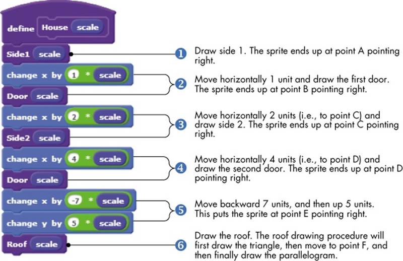
Figure 4-25. The House procedure. Note how the major tasks align with the drawing plan.
The individual procedures for drawing the house are shown in Figure 4-26. These procedures draw simple geometric shapes using the same techniques you learned in Chapter 2.
The Side1, Door, and Side2 procedures draw 3×5, 1×2, and 9×5 rectangles (scaled by the factor scale), respectively. The Roof procedure has two sub-procedures (named Triangle and Parallelogram) for drawing the two parts of the roof. Note that the scaling factor scale was used consistently in all these procedures. This allows us to draw larger or smaller houses by calling the House procedure with a different argument.
TRY IT OUT 4-3
Did you notice that the Side1, Door, and Side2 procedures use almost identical code? Create a new procedure named Rectangle that takes the length, width, and scale as parameters and draws a rectangle of the specified dimensions. Modify the Side1, Door, and Side2 procedures to call the new Rectangle procedure.
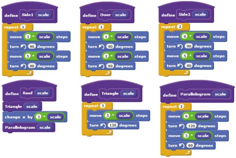
Figure 4-26. Procedures for drawing the house in Figure 4-24
Building Up with Procedures
FlowerFlake.sb2
Another way to deal with a large problem is to focus on the smaller details first. If you solve a large problem’s smaller pieces (or find solutions that already exist), you can then assemble the results from the bottom up to reach a total solution.
To demonstrate this problem-solving technique, let’s start with a simple procedure (called Leaf) that draws a single leaf as shown in Figure 4-27. The procedure contains a repeat loop that runs twice to draw the two halves of the leaf. Each half is drawn as a series of 15 short line segments with a 6° turn angle between them. This is similar to the method of drawing polygons we used in Chapter 2.
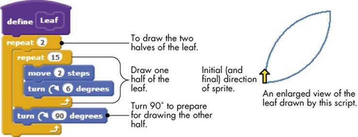
Figure 4-27. The Leaf procedure and its output
Using this procedure as a starting point, we can now draw a slightly more complex shape that contains five leaves. Our new procedure, called Leaves, and its output are shown in Figure 4-28. As you can see, we only had to call the Leaf procedure in a repeat loop with an appropriate turn angle in between.
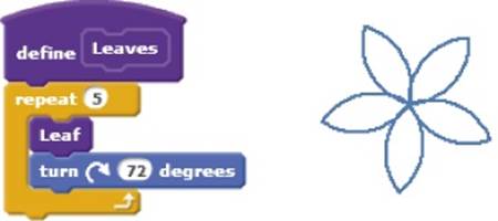
Figure 4-28. The Leaves procedure calls the Leaf procedure five times with 72° turn angle between each call.
We can now use Leaf and Leaves to build up something that is even more complex: a branch with leaves on it. Our Branch procedure and its output are illustrated in Figure 4-29. The sprite moves forward 40 steps, draws a single leaf (by calling the Leaf procedure), moves an additional 50 steps forward, draws five leaves (by calling the Leaves procedure), and finally returns to its starting position.
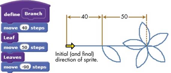
Figure 4-29. The Branch procedure and its output
Let’s take this up another notch. How about using the Branch procedure to create a complex drawing of a flower? Our new procedure, called Flower, and its output are shown in Figure 4-30. The procedure simply calls the Branch procedure six times in a loop with 60° turn angle in between.
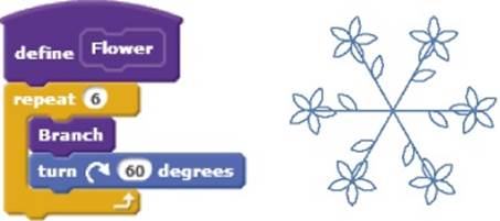
Figure 4-30. The Flower procedure and its output
We can keep going on and on, but the idea should now be clear. We started with a simple procedure called Leaf and used it in a new procedure (called Leaves) to create a complex pattern. The Branch procedure relied on these two procedures to create something more complicated. TheFlower procedure then used Branch to draw an even more complex pattern. If we wanted to, we could create a procedure that draws an entire tree of flowers and yet another to draw a garden full of trees.
The point to take away from this example is that, regardless of the complexity of the problem we are trying to solve, we can always build the solution by gluing together a number of smaller, more manageable pieces. Using this problem-solving technique, we start with short procedures that solve very simple problems and then use them to create more sophisticated procedures.
Summary
In this chapter, we introduced a number of fundamental concepts that will be used extensively in the remainder of this book. First, we explained the concept of message broadcasting for intersprite communication and synchronization. After that, we introduced structured programming and discussed how to use message broadcasting to implement procedures. We then demonstrated the build-your-own-block feature of Scratch 2.0 and explained how to pass arguments to procedures to make the procedures more flexible. We went over several examples that demonstrated dividing a large problem into smaller, more manageable pieces and explained how to use procedures as the basic building blocks for creating large programs. Last, we examined a bottom-up problem-solving technique, in which we put together known solutions to smaller pieces of a problem to solve the big problem.
In the next chapter, you’ll learn about the most important concept in any programming language: variables. This introduction to variables will be an essential next step in becoming a proficient programmer.
Problems
|
Q: |
1. Write different procedures to draw each letter of your name. Name each procedure for the letter that it draws. Then write a script that calls these procedures so you can draw your name on the Stage. |
|
Q: |
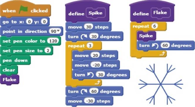
2. Create the program shown below, run it, and explain how it works.
|
|
Q: |
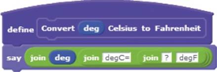
3. Write a procedure that converts degrees Celsius to degrees Fahrenheit as shown below. Have the script round the answer to the nearest integer. Test your procedure for different temperatures. (Hint: °F = (9 / 5) × °C + 32.)
|
|
Q: |
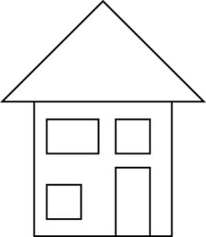
4. Write a procedure to create the house shown on the right. Start by writing small procedures that draw small parts of the house (for example, door, roof, windows, and so on). Then combine these procedures to create the entire house.
|
|
Q: |
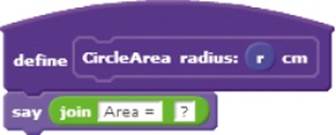
5. Write a procedure to compute the area of a circle (A = πr2) given its radius, as shown below. Use π = 3.14.
|
|
Q: |
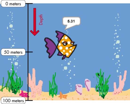
6. In this exercise, you’ll simulate the pressure experienced by fish under water. Assume that the pressure P (in atmospheres) felt by a fish is related to its depth d (in meters from the surface) by the relation: P = 0.1d + 1. PressureUnderWater_NoSolution.sb2 contains a partial implementation of this simulation. Finish the script so that the fish says the pressure it feels while swimming, as illustrated below: PressureUnderWater_NoSolution.sb2
|
All materials on the site are licensed Creative Commons Attribution-Sharealike 3.0 Unported CC BY-SA 3.0 & GNU Free Documentation License (GFDL)
If you are the copyright holder of any material contained on our site and intend to remove it, please contact our site administrator for approval.
© 2016-2026 All site design rights belong to S.Y.A.