SketchUp For Dummies (2017)
Part 4
Sharing What You’ve Made
Chapter 14
Creating Presentations and Documents with LayOut
IN THIS CHAPTER
![]() Managing pages and layers
Managing pages and layers
![]() Inserting and updating SketchUp models
Inserting and updating SketchUp models
![]() Adding graphics
Adding graphics
![]() Creating labels and dimensions
Creating labels and dimensions
![]() Customizing LayOut with your own templates and scrapbooks
Customizing LayOut with your own templates and scrapbooks
![]() Printing, exporting, or presenting your work
Printing, exporting, or presenting your work
If you’re lucky enough to have SketchUp Pro, you also have LayOut, a separate application for presenting 3D SketchUp models. LayOut was designed to be easy to use, quick to learn, and tightly integrated with SketchUp.
The people who built LayOut want you to use it to create all your design presentations. Here are examples of what you can make:
· Design packs, presentation boards, and posters
· Construction drawings with scaled views and dimensions
· Storyboards for planning camera shots
LayOut gives you the tools to add company branding, accurate dimensions, shading and hatching patterns, and more — whatever needs to accompany views of your model. You can create presentations that are just about any physical size and export them as PDFs or images to send to other people.
 Best of all, when your design changes in SketchUp, you can easily update your model views in LayOut to reflect the changes. If you make your living designing and presenting ideas in 3D, LayOut can save you boatloads of time.
Although this book can’t dig into all that LayOut can do, this chapter helps you start using LayOut’s key features for presenting your models.
Building a LayOut Document
To help you get your bearings in LayOut, this section helps you put together a LayOut document. Take a deep breath, put a fresh battery in your mouse, and prepare for your presentation-making life to get much easier than it’s ever been… .
When you launch LayOut (or each time you start a new LayOut document), the Getting Started dialog box appears and asks you to select a template. You can change this default behavior if you like, but the templates are usually the easiest way to begin.
In Figure 14-1 , all the template options are expanded so you can have a look at all the categories of options. The template selected in Figure 14-1 is a Titleblock template that uses simple serif fonts and a standard U.S. letter document size (8 ½ x 11 inches). Whether you start with a prebuilt template or create your own, the following sections walk you through the basics of creating a presentation in LayOut.
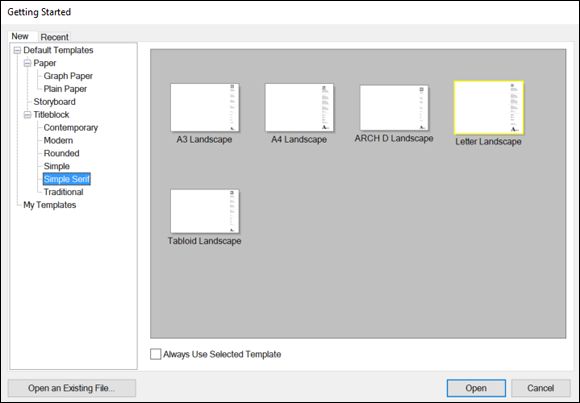
FIGURE 14-1: Select a template in the Getting Started dialog box.
Customizing a document’s pages and layers
Many LayOut templates have multiple pages and layers, as shown in Figure 14-2 . When you use pages and layers together, they give you a lot of control over what appears where in your document:
· Pages: Your document can have as many pages as you like. In the Pages panel on the right, you can customize the number and sequence of pages. To add a page, click the plus sign icon. To duplicate a page, click the Duplicate Selected Page icon. To delete a page, click the minus sign icon. To change the order of the pages, click and drag a page up or down in the sequence.
· Layers: In LayOut, the layers work like sheets of acetate stacked one on top of another. (This functionality is very different from SketchUp layers, covered in Chapter 7 .) In the Layers panel, you can add layers that control what does or doesn’t appear on each page. Two features enable you to manage layers: layer visibility (the eye icon) and layer sharing (the single or double page icon).
In a template, layers may be locked by default so that you can’t accidentally move things. To customize the template with your own information, unlock each layer by clicking its little lock icon. Figure 14-3 helps you find these important controls in the Layers panel.
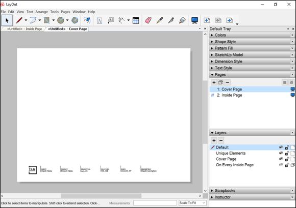
FIGURE 14-2: Pages and layers enable you to control what appears where in a document.
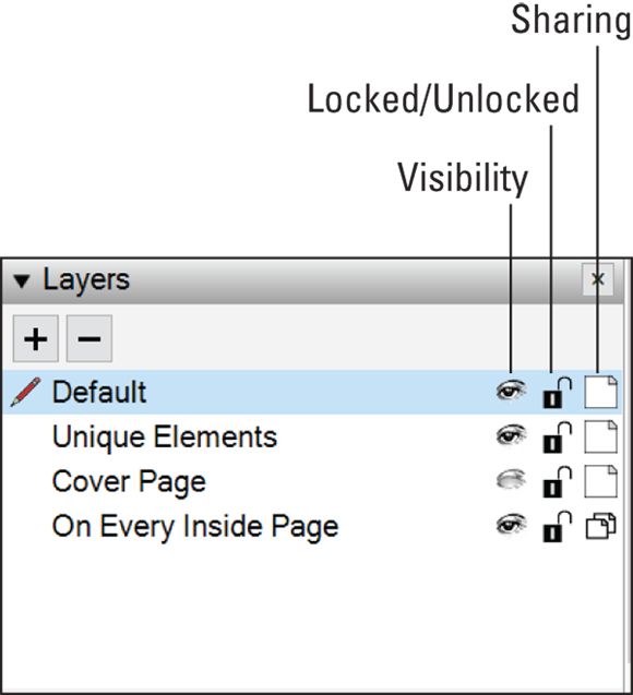
FIGURE 14-3: In LayOut's Layers panel, icons control sharing and visibility.
To add an element on almost every page, follow these steps:
1. In the Layers panel, create a layer or select an existing layer.
The layer with the little red pencil next to it is your active layer.
2. Click the layer’s sharing icon so that it looks like two pages (not one).
This step shares whatever you add to this layer on every page in your document.
3. Create an element, such as typing text, drawing a shape, or inserting a SketchUp model or image.
You discover how to add items to a page in the upcoming sections.
4. In the Pages panel, select any page on which you don’t want the item to appear.
5. Back in the Layers panel, click the eye icon so that the eye closes and the layer is toggled to its hidden state.
The element becomes hidden on the selected page. In Figure 14-2 , notice that Cover Page is selected in the Pages panel. To create a custom cover page, the On Every Inside Page layer is hidden.
In the Layers panel, when a layer is shared among all your pages, you can control the layer’s visibility on the selected page by toggling the eye icon.
Conversely, if you want an element to appear on only one page, follow these steps:
1. In the Pages panel, select the page on which you want the element to appear.
2. In the Layers panel, click the plus icon to create a new layer or select a layer that displays elements only on the selected page.
3. Click the layer’s sharing icon so that it looks like a single page.
4. With the page and layer selected, create the element on the new layer.
 As you create a document, keeping your elements organized with pages and layers can save your sanity. Here are a few tips to help you on your way:
· To keep track of what each page and layer does, give each one a descriptive name, similar to the names you see in the template shown in Figure 14-2 . To name a page or layer, double-click its name, and the name becomes editable.
· To see what layer an element is on currently, select the element and look for the tiny blue dot in the Layers panel. If you select two elements on two different layers, you see two blue dots.
· To change which layer something is on, select the destination layer in the Layers panel. Then context-click the element you want to move and choose Move to Current Layer. Selecting multiple elements, context-clicking one of them, and choosing Move to Current Layer moves them all.
· Move several elements from multiple layers to a single layer with Copy and Paste. Copying elements from multiple layers and pasting them pastes them all on the same layer — the active one.
Adding and editing text
LayOut enables you to add plain old text with the Text tool, and it’s easy to do. Labels and dimensions, covered later in this chapter, have a few whiz-bang features that regular text does not.
Text boxes in LayOut are classified into two broad types, depending on how you create them:
· Bounded: If you click and drag with the Text tool, the text box you create is bounded. Any text you enter into it that doesn’t fit isn’t visible, and you get a little red arrow at the bottom. That arrow tells you that there’s more in your text box; you need to use the Select tool to make the box bigger to show everything that’s inside. Use a bounded text box whenever your text needs to fit into a precise space in your design.
· Unbounded: If, instead of creating a text box with the Text tool, you simply click to place your cursor somewhere on your page, the text you create is unbounded. It stays inside a text box, but that text box automatically resizes to accommodate whatever text you put inside it. To turn an unbounded text box into a bounded one, just resize it with the Select tool or choose Text ⇒ Make Unbounded.
Naturally, you control things like text size, color, alignment, and font using the Text Style panel (Fonts dialog box on a Mac). Select the text you’d like to format and choose your desired settings in the panel.
As you add and edit text in LayOut, here are a few tips to help you along the way:
· To edit text, double-click a text element with the Select tool. When you’re done, click elsewhere on the page.
· Zoom into your document if you need to add or edit text precisely. See the nearby sidebar, “Get zooming ,” for details.
· Choose Text ⇒ Insert Auto-Text to insert a tag that displays automatically generated text. For example, you can insert page numbers or a company name. To customize the text that appears for a specific Auto-Text tag, choose Text ⇒ Customize Auto-Text, and in the dialog box that appears, select the tag at the top and type your desired text in the specified area at the bottom.
· On a Mac, choosing Text ⇒ Show Rulers does more than just display ruled increments at the top of your drawing window. It also enables extra controls for paragraph spacing and lists — bulleted and numbered. Just select text in your document to see them appear above the ruler.
GET ZOOMING
Zooming in can help you add and edit document elements precisely, and zooming out helps you check how your overall document looks. Here are three ways to zoom around your document:
· Roll your scroll wheel to zoom in and out on the page, just like in SketchUp.
· While you’re zoomed in, hold down the scroll-wheel button to pan around.
· To fill your drawing window with the page you’re viewing, choose Scale to Fit (Zoom to Fit on the Mac) from the Zoom drop-down list in the lower right.
Inserting SketchUp model views
With every other page-layout program in the universe, the only way to include a view of a SketchUp model is to export that view from SketchUp as an image file and then place it in the layout program. Changing the SketchUp file means going through the whole export-and-place process again. If your presentation includes lots of SketchUp model views, this process can take hours.
This brings us to LayOut’s raison d’être: Instead of exporting views from SketchUp to get them into LayOut, all you do is insert a SketchUp file. From within LayOut, you can pick the view you like best. You can also use as many views of the same model as you want. When your SketchUp file is modified, LayOut knows about it and (using the References panel in the Document Setup dialog box) lets you update all your views at once by clicking a single button. If you need to pause for a minute to let the timesaving aspects of this feature sink in, we understand.
Follow these steps to insert a SketchUp viewport (model view) into your document:
1. In SketchUp, create a scene for each view of your model that you want to show in your LayOut document. When you’re done, save your document.
Take a look at Chapter 11 for a refresher on using scenes. Be sure to give them meaningful names.
2. In LayOut, on the Pages panel, select the page where you want to insert a viewport.
3. Choose File ⇒ Insert.
4. In the Insert dialog box that appears, find the SketchUp file on your computer that you want to insert and click the Open button.
The Insert dialog box closes, and your SketchUp model is placed on your current LayOut document page.
5. With the Select tool, context-click your viewport, choose Scenes, and then choose the name of the scene you want to appear in this viewport, as shown in Figure 14-4 .
If you don’t see a list of scenes, you probably forgot to save your SketchUp file in Step 1. Save your SketchUp file; then context-click your viewport (in LayOut) and choose Update Reference.
6. (Optional) Assign a drawing scale to your model view if that’s appropriate.
If the scene you picked in Step 5 is an orthographic view (top, front, side) where perspective is turned off, you likely want to show your model at a particular drawing scale. See “Creating scaled orthographic views ” later in this chapter for details.
7. Use the Select tool to position or resize your model view.
Click and drag to move any element in your document on the page. Click and drag the Rotation Grip (the little blue stick in the center of your image when it’s selected) to rotate. You can resize anything by clicking and dragging any corner.
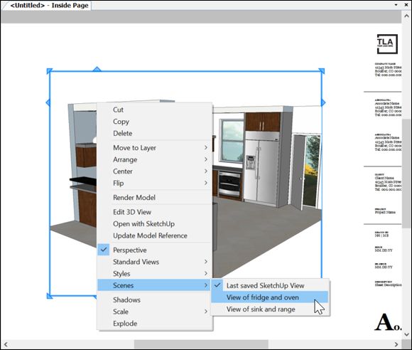
FIGURE 14-4: Associate a scene from your model with a viewport in LayOut.
If a bright yellow exclamation mark icon appears in the lower-right corner of a viewport, you need to tell LayOut to render that viewport so that it reflects whatever changes you’ve made. Context-click the viewport, choose Render Model from the context menu, and you’re good to go.
Repositioning a model view in LayOut
In LayOut, when you’re working inside a model viewport, you’re working in 3D. You can do a couple of things to change your viewport’s point of view: Use the Camera tools or edit scenes with the Model panel.
Double-clicking a viewport with the Select tool is a little bit like activating SketchUp from inside LayOut. When you’re in this SketchUp-like mode, the thick blue border around the model viewport becomes a thin blue border. When you’re in this model, you can change your point of view as follows:
· Orbit, zoom, and pan around using your mouse, exactly the way you do in SketchUp.
· Context-click the viewport and choose a specific Camera tool from the context menu (Orbit, Pan, Zoom, Zoom Window, Look Around, or Walk).
· On the SketchUp Model panel’s View tab, shown in Figure 14-5 , choose an option from the Scenes or Standard Views drop-down lists.
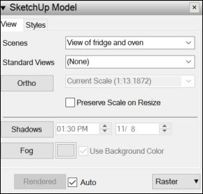
FIGURE 14-5: The SketchUp Model panel in LayOut.
When you’re done repositioning your model, click somewhere else to stop editing the viewport. LayOut re-renders the view, and your model goes back to looking nice and crisp.
Making your models look their best
The SketchUp Model panel’s second tab — Styles — contains one of the most important settings in all of LayOut: the Line Weight field. The number you put into the Line Weight field tells LayOut how thick to draw the thinnest lines in your viewport. Entering 2 yields edges that are 2 points wide. Typing 0.25 makes your edges a quarter point wide — much thinner and (in many cases) much nicer. Figure 14-6 illustrates how adjusting this setting changes how a model looks.
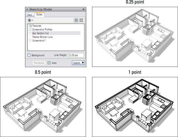
FIGURE 14-6: Use the Line Weight field to make your models look their very best.
Changing the Line Weight number is the single best thing you can do for your models in LayOut. The line weights you use depend entirely on the size of your viewports and the complexity of your drawings. Try to avoid making anything look too wispy or too chunky — the key here is readability.
 If the style that’s applied to your viewport has Profiles enabled, some edges look thicker. To change the thickness of Profiles in a viewport, edit the style that defines the Profiles in the SketchUp model. Profile thickness is always a multiple: A setting of 4 produces Profiles that are four times as thick as regular edges. Check out Chapter 10 for more about styles and how to edit them.
How LayOut renders a model can also have a big impact on your model’s appearance. You control the rendering on the SketchUp Model panel’s Styles tab: In the lower right, a drop-down list enables you to select Vector, Raster, or Hybrid. Here’s how selecting each option impacts how your model is rendered (and check out Figure 14-7 to see examples of each rendering style):
· Raster: Renders your viewport as an image comprising many, many little dots. If your model is rendered as a raster, it can display sketchy styles, shadows, and other effects that make it look like it does in SketchUp. On the other hand, printing or exporting a raster image at large sizes involves truckloads of pixels, and that can make LayOut choke. See the nearby sidebar “Balancing performance and quality ” to find out more.
· Vector: Renders your selected model viewport as a vector image. Lines appear smooth and crisp, but things like shadows, textures, and sketchy styles don’t appear. Also, choosing vector rendering for really complex models can take a long time to process.
· Hybrid: Combines clean vector lines with rich raster faces, shadows, and other goodies. Behind the scenes, LayOut renders the model twice — once as a vector and once as a raster. Hybrid rendering takes even longer than vector rendering but produces very nice results. If you have time, try hybrid rendering to see how it looks.
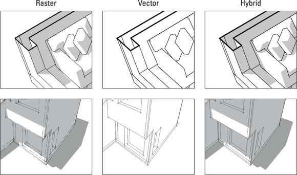
FIGURE 14-7: Choose a rendering method for each viewport in your LayOut document.
Try raster rendering for models with Sketchy Edges styles and for any model with a lot of geometry. Select hybrid or vector rendering for any plans, sections, or other views that feature a lot of line work.
BALANCING PERFORMANCE AND QUALITY
The more complex your SketchUp model is, the longer it takes to render in LayOut. If LayOut is sluggish, adjusting a couple of rendering settings might put a little spring in its step. Try the following:
· Select File ⇒ Document Setup ⇒ Paper. From the Display Resolution drop-down list, select Low, which corresponds to a resolution of 72 ppi (pixels per inch).
· On the SketchUp Model panel, clear the Auto check box in the lower left. Doing so tells LayOut not to render a model viewport each time you edit it. Instead, LayOut waits until you click the Render button (next to the check box) before it does any rendering.
Creating scaled orthographic views
The first step in creating a dimensioned drawing is to turn your viewport into a 2D orthographic view of your model. (See Chapter 11 for an introduction to orthographic views.) Although you can use the controls in the SketchUp Model panel to accomplish this, a better way is to go back to the model and create a scene.
Follow these steps to save an orthographic scene in your SketchUp model and assign it to a viewport in LayOut:
1. In LayOut, context-click (with the Select tool) the viewport that contains your model and choose Open with SketchUp.
2. If you plan to have an active section cut in your view, add it to your model (if you haven’t already).
Chapter 11 explains how to make section cuts.
3. In SketchUp, choose Camera ⇒ Parallel Projection; then choose Camera ⇒ Standard Views ⇒ Top (or any other option from this list except Iso).
4. Zoom and pan (but don’t orbit) until you have the view you want and then choose View ⇒ Animation ⇒ Add Scene.
5. Save your model and close it.
6. In LayOut, context-click the viewport and choose Update Reference.
7. In the View tab of the SketchUp Model panel, choose your new scene to associate it with the viewport.
Now that you have an orthographic view of your model, you can assign a scale to it. Here’s everything you need to know about that:
· Assign a scale using the Scale drop-down list in the SketchUp Model panel. Don’t forget to select the viewport you’re working on first. Alternately, with the Select tool, context-click your viewport, choose Scale, and then choose one from the list that appears, as shown in Figure 14-8 .
· Create your own scales if you want. Need a scale that doesn’t appear in the default list? Choose Edit ⇒ Preferences (LayOut ⇒ Preferences on a Mac) to open the Preferences dialog box; then click Scales on the left. Click the plus sign to add a new scale to the list. Scales you add are available for any LayOut file you’re working on.
· Make sure Preserve Scale on Resize is selected. After you assign a scale to a viewport, you probably want to manually resize its boundaries with the Select tool. Before you do, make sure the Preserve Scale on Resize check box (in the SketchUp Model panel) is selected. If it’s not, you change the scale of your model view when you try to resize its viewport.
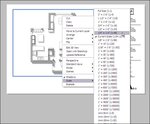
FIGURE 14-8: Assign a precise drawing scale to any orthographic viewport.
LayOut lets you assign a scale to any old view, but that doesn’t matter. Drawing scales apply only to nonperspectival, straight-on views of your model.
Updating model references
If you ever aren’t sure whether your SketchUp viewports reflect the latest changes to your SketchUp model file (the .skp file), LayOut enables you to check. Select File ⇒ Document Setup ⇒ References. You see a list of files that the LayOut document references and whether those references are current. To update any SketchUp model file manually, select it in the list and click Update. The SketchUp file must be saved to your hard drive for the update process to work.
Adding photos and other graphics
Inserting images into your LayOut document is a straightforward affair. Just choose File ⇒ Insert and take it from there. A few more things to know about images you insert:
· LayOut can insert raster images. Raster images are made of pixels, or tiny dots. TIFF, JPEG, GIF, BMP, and PNG are all graphics file formats that save pictures as lots of tiny dots.
· The Mac version of LayOut can also insert PDFs. This is indisputably the best way to bring in vector art, such as logos. You can use a program like Adobe Illustrator to save any AI (Illustrator) or EPS file as a PDF.
· Images are a lot like viewports. The techniques for moving, resizing, and rotating images work just like they do for SketchUp model views; use the Select tool to do everything. Remember to hold down the Shift key when you resize to maintain your image’s aspect ratio.
Unfortunately, LayOut offers no easy way to import editable vector (such as AI, EPS, and SVG) graphics. If you want to use vector graphics in your LayOut document, you have two choices:
· Make your own. LayOut is a fantastic vector illustration tool. The upcoming section, “Drawing with LayOut’s vector tools ,” helps you get started.
· Borrow shamelessly from the Scrapbooks panel. One of the best things about LayOut is the hundreds — maybe thousands — of predrawn graphical elements you can find in the Scrapbooks panel (shown in Figure 14-9 ). You find things like
o Symbols: Arrows, section markers, north indicators, graphic scales, and column grids
o Entourage elements: Trees, cars, and people at various scales and levels of detail
o Color palettes: To help with producing attractive documents quickly
To use something you see in the Scrapbooks, just click it with the Select tool to sample it and then click again to stamp it onto your page. You can keep clicking to stamp more copies. Press the Esc key when you’re ready to exit stamping mode.
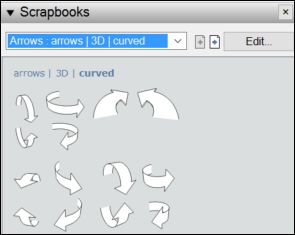
FIGURE 14-9: Scrapbooks contain all sorts of images you can insert into a LayOut document.
Drawing with LayOut’s vector tools
LayOut includes a full slate of drawing tools that you can use to create logos, title bars, north arrows, graphic scales — anything you want. The drawings you create are vectors, meaning that you can do the following:
· Scale the drawings without losing quality.
· Change the fill and stroke (outline) colors.
· Split lines and then rejoin them to make new shapes.
Because we don’t know what you want to draw, a step list would be pretty pointless here. Instead, here are a few pointers to get you started:
· Create shapes the same way you create them in SketchUp. Lines, arcs, rectangles, circles, polygons — you see the same or similar tools, and you can (for the most part) click-move-click to create the shapes just as you do in SketchUp.
· Type measurements and angles. LayOut has a Measurements box (in the lower-right corner of your screen), just like the one in SketchUp. Take a look at Chapter 3 for tips on working accurately with this box.
· ![]() Build complex shapes out of simpler ones. For example, with the Split tool and the Join tool, you can combine a triangle and a rectangle to create a thick, blocky arrow.
Build complex shapes out of simpler ones. For example, with the Split tool and the Join tool, you can combine a triangle and a rectangle to create a thick, blocky arrow.
· Use the right kind of snaps. You can snap to objects or to a grid via the Arrange menu.
· Open the Shape Style panel. Use the Shape Style panel to change the fill and stroke characteristics of the selected shape(s). In plain English, double-click the Fill, Pattern, or Stroke swatches to open a panel where you can pick colors and patterns for the things you draw. The controls are straightforward, so you don’t need much help from us; just experiment and see what happens. You can also select dashed lines or add arrows to the beginning or end of a line.
If you’re a pro, such as an architect or engineer, who needs to represent different materials using standardized patterns called hatches, LayOut has you covered — and more importantly, helps you cover your drawing. LayOut includes some of the most common hatches (which it calls Material Symbols), as well as hatches for Geometric Tiles, Site Patterns, and Tonal Patterns (which include dots and lines of various sizes). To apply these hatches (or any pattern) to a shape in your LayOut document, select the shape, double-click the Pattern swatch in the Shape Style panel. In the Pattern Fill panel that opens, select a category from the drop-down list at the top, and then select your desired hatch or pattern among the swatches that appear. Figure 14-10 shows this process in action.
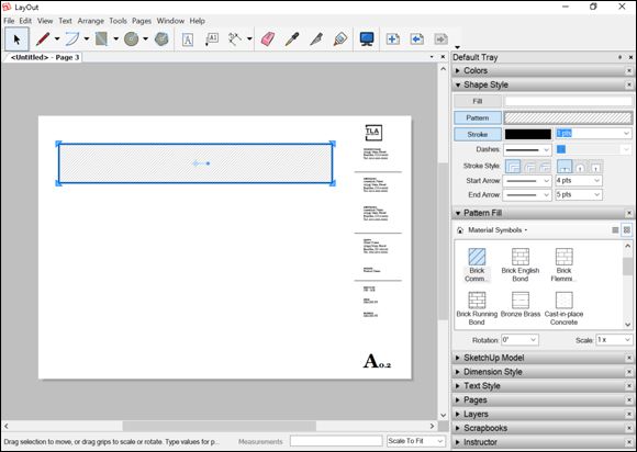
FIGURE 14-10: Draw shapes and customize their outlines, fills, pattern, and color.
Annotating with labels
In LayOut, labels are the easiest way to add callouts (notes with leader lines) to models and drawings. With the Label tool, you can add labels wherever you need them. Here are six important points about one of the most useful tools in LayOut:
· Activate, click, click, type, and click. Activate the Label tool, click once to pin the end of the leader line to an element in your drawing, click again to place your text cursor, type something, and click somewhere else to finish your label, as shown in Figure 14-11 .
If you want, you can create curved leader lines. They often do a better job of standing out when most of the shapes in your drawings have straight edges. In LayOut, you curve a leader line by click-drag-releasing your mouse when you’re placing its endpoints. (You can also do this with lines created with the Line tool.)
· Save time with auto-filled text. When you label certain kinds of entities in a model viewport, LayOut automatically fills in the text part for you. Labeling a component gives you its name. Labeling a face gives you its area. If you don’t want LayOut’s suggestion, just type something else.
· Leader lines stick to drawing elements. When you move the thing your leader line is pinned to, the line moves with it.
· Use the Shape Style panel to edit the look of your leader lines. You can change the color, thickness, and endpoints (arrowheads, slashes, and dots) of any leader line very easily after you create it.
· Save time by sampling. After you edit a label, making every subsequent label match is easy:
1. Activate the Label tool and then press the S key.
Your cursor changes into an eyedropper.
2. Click the text part of the label you sample and then click S again.
3. Click the leader line of the label you sample.
Now every label you create looks just like the one you sampled.
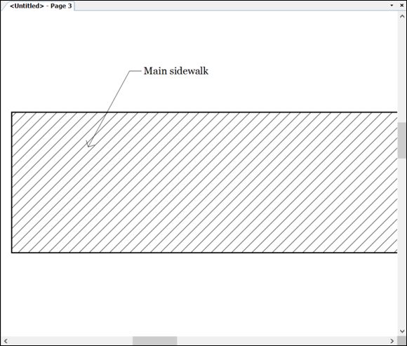
FIGURE 14-11: Add text callouts with the Label tool.
Displaying dimensions
Dimensions can display exact measurements based on your model or drawing.
The dimensions tools work hand-in-hand with inserted models to save you hours of work. For example, if you add a dimension to an inserted SketchUp model and later change the dimension of your model, LayOut can know about those changes and update the inserted model and the dimension accordingly.
Before you use either dimension tool, make sure Object Snap is turned on. (It’s on by default.) With Object Snap on, your dimension leader lines can “see” the points to which they’re supposed to attach. On the Arrange menu, you can check the status of Object Snap.
To create a linear dimension, follow these steps:
1. Select the Linear Dimension tool.
2. Click a start point, and then click an endpoint.
3. Click to define an offset, and you’re done.
After you create your first dimension and while the tool is still active, double-click the next point you want to dimension. This technique duplicates the offset that you set for the first dimension.
Angular dimensions are a little trickier than linear dimensions. Follow these steps to make it work (see Figure 14-12 ):
1. Activate the Angular Dimension tool.
2. Click somewhere along the first line for the angle you want to mark, and click again along that line.
You create two “pin points” that establish the first line of the angle you want to mark.
3. Click somewhere along the second line that creates the angle, and click again.
You create second set of pin points that tells LayOut where the other line of the angle is.
4. Click one last time to position the text of your angular dimension.
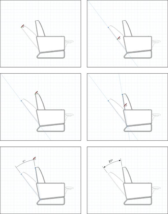
FIGURE 14-12: Creating an angular dimension takes some getting used to.
Creating separate layers for text, labels, and dimensions saves time in the long run. See “Customizing a document’s pages and layers ” earlier in this chapter for details.
Editing dimensions
After you actually draw a dimension — linear or angular — on your page, you can do an awful lot to change what the dimension looks like. To begin with, take a look at the anatomy of a dimension. Figure 14-13 shows an example of each kind.
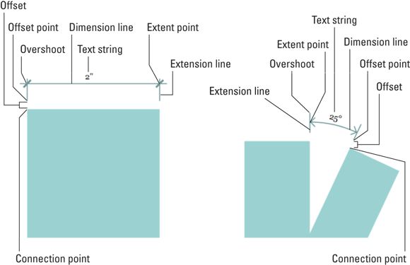
FIGURE 14-13: The anatomy of a LayOut dimension. Linear on the left, angular on the right.
Now that you’re clear on nomenclature, here’s some advice on editing a dimension’s appearance (basically, everything except its text box):
· Use the Shape Style panel to change colors, line styles, line weights, and arrow styles (the things at the ends of dimension lines).
· Use the Text Style panel to change the font, text size, and so on.
· Use the Style tool to copy formatting and other settings from one dimension to another. Activate the Style tool, click your “source” dimension, and then click each dimension you want to change.
· Double-click a dimension to access all its internals. After they become editable, you can click and drag the dimension‘s connections points, offset points, extent points, or text all you like.
· Select individual lines to edit them. After you double-click a dimension, you can select its constituent lines to edit them. Aidan likes to draw dimension lines slightly thicker than extension lines, so he selects the dimension line and increases its width in the Shape Style panel.
· Overshoots can be tricky. The overshoot (as shown in Figure 14-13 ) is the part of an extension line that extends beyond the dimension line. You can adjust your overshoot’s length if you like. Here’s how:
1. Double-click a dimension to edit it.
2. Click to select the extension line whose overshoot you want to adjust.
3. Change the number beside the End Arrow setting in the Shape Style panel.
Unfortunately, there’s no way to alter both extension lines’ overshoots simultaneously. After you change one line, choose Edit ⇒ Copy Style; then select the other and choose Edit ⇒ Paste Style.
After a dimension looks just the way you like, copying a dimension’s style and applying it to your other dimensions is pretty easy. Just use the Style tool to transfer formatting from one dimension to the other.
![]() To sample a dimension’s style so that every new dimension you draw matches it, select the Style tool (or press the S key) and click your source dimension before you draw the next one.
To sample a dimension’s style so that every new dimension you draw matches it, select the Style tool (or press the S key) and click your source dimension before you draw the next one.
Take a gander at the Dimension Style panel, as shown in Figure 14-14 . Most of the controls here are obvious, but some definitely aren’t. Diving right in:
· Text position: Choose to display a text string above, below, or right smack dab in the middle of its corresponding dimension line.
· Text alignment: Force a text string to always be horizontal or vertical on the page, or aligned (parallel) or perpendicular to its dimension line.
· Display units: People who use the Imperial system of measurement tend to show the units on their dimensions. Metric folks tend not to. You have the choice.
· Auto Scale button: Here’s where dimensions start to get a bit complicated. For a full discussion of what the heck this button does, see the next section.
· Scale drop-down list: This is available only when Auto Scale is deselected. Skip ahead to read all about model space and paper space. Getting your head around this topic takes time.
· Length: Different professions have different conventions for the dimensions they put on their drawings. Choose the one that suits you best.
· Precision: If you dimension the overall length of an airport runway, you probably don’t need to be accurate to the 1000th of an inch. However, if you design an artificial heart valve …
· Angle: Degrees or radians — you decide. Sometimes, software reminds you that math nerds create it.
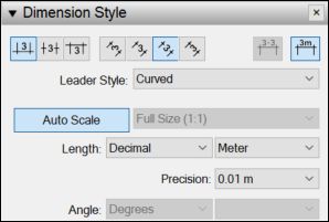
FIGURE 14-14: The Dimension Style panel.
Keeping track of model space and paper space
When you place a SketchUp model viewport on your page, you end up with two types of space in your LayOut document:
· Paper space: Distances that pertain to the physical sheet of paper you’re working on are said to be in paper space. A 4-x-4-inch blue square in paper space is 4 inches long.
· Model space: Distances within a model viewport have nothing to do with the size of the sheet of paper the viewport is on. An 80-x-80-foot building shown at 1 inch = 8 feet scale is 80 feet long in model space. In paper space, it’s 10 inches long.
A dimension you draw in LayOut is either in paper space or in model space. Which one the dimension is in by default depends on what the dimension is connected to:
· Viewports: When you draw a dimension between two points in a model viewport, LayOut is smart enough to presume that you want to display the length between the points in the model (in model space).
· Everything else: When you create a dimension between two points that have nothing to do with a viewport, LayOut assumes that you want to see the actual length on the page (in paper space).
Figure 14-15 illustrates the difference between model space and paper space. Both dimensions are exactly the same physical length on the page: 3 inches. However, the dimension on the left is attached to two points on a SketchUp model that’s shown at 1 inch = 8 feet scale. This dimension displays the model space length of 24 feet (3 x 8), whereas the dimension on the right shows its paper space length of 3 inches.
FIGURE 14-15: Dimensions can either show model space or paper space.
The Auto Scale button in the Dimension Style panel is automatically selected whenever you create a new dimension. If your dimension touches a point in a model viewport, the text string displays the length in model space. If it doesn’t touch any model viewport at all, you get a length in paper space.
Turning off Auto Scale lets you assign a scale to the dimension you select. Choosing 1 inch = 60 feet for a dimension that’s physically 4 inches long makes its text string read 240 feet — no matter what the dimension is attached to.
Creating tables
If you create construction documents, the Table tool is for you. New in LayOut 2017, the table feature enables you to easily add construction schedules, area and quantity takeoffs, legends, or whatever you need in order to help others understand your LayOut document.
To start creating tables, here are the basics:
· To create a table, select the Table tool, click to set the upper-left corner, move the cursor until your desired number of rows and columns appears, click to set the table’s lower-right corner, and click one more time to adjust the table dimensions.
· To add text to a table, double-click the table to access the table cells. Click in a cell and type the text you want to appear.
· To edit a table’s line width and background, select the table and use the Shape Style panel.
· To edit the rows, columns, and cells, double-click the table and then context-click to see a menu of options.
LayOut tables include a few cool features for creating and managing table data:
· If your table data is already saved as an Excel (.xlsx ) or CSV (.csv ) file, then you can import that data into LayOut and save yourself a bunch of time. To import the file, choose File ⇒ Insert, select the file, make sure the correct sheet is selected, and click OK. You can also choose to import the table formatting from Excel.
· After you import a table, managing changes between your table's source file and LayOut is super easy. If you need to update the source file, then you can update your table in LayOut by context-clicking the table and choosing Update Table Reference from the menu that appears.
Creating Your Own Templates
Most of the design presentations that you (or your firm) put together probably look alike — after all, they’re part of your brand identity. If the presentation documents you make are all variations on a couple themes, why not build your own templates and use them every time you start a new project? You can set up LayOut so that your templates appear in the Getting Started dialog box, making it easier to build consistent presentations, quicker.
Follow these steps to turn any LayOut file into a template:
1. Build a LayOut file that includes all the elements you want.
These elements may include a title block, a logo, page numbering, and a cover page. You probably also want to set up things you can’t see, such as Auto-Text tags, a layering system, and even premade, empty pages for content. To make sure your template captures everything, you can strip all the content out of a LayOut document that you’ve already made and then save the resulting shell as a template.
Before you move to Step 2, make sure you’re viewing the page that you want to use as the thumbnail preview in the template list.
2. Choose File ⇒ Save as Template.
The Save As Template dialog box opens.
3. Type a name for your template and then choose a location for your new template.
In the list at the bottom of the dialog box, click the folder (they’re all folders) in which you want to include the template you’re adding.
4. Click OK (Save on a Mac).
The next time the Getting Started dialog box appears, your new template will be in it.
Putting Together Your Own Scrapbooks
Most hardcore LayOut users make their own scrapbooks of scale figures, cars, trees, drafting symbols, typography — anything they need to use again and again.
Like templates, scrapbooks are just LayOut files that have been saved in a special folder on your system. When you open the program, it checks that folder and displays the files it finds in the Scrapbooks panel.
Follow these steps to build your own LayOut scrapbook:
1. Build a LayOut file with the elements you want to include in your scrapbook.
2. Choose File ⇒ Save As Scrapbook.
3. Type a name for your scrapbook.
In the Save As Scrapbook dialog box, the Scrapbook Folder list shows the location of the folder where your new scrapbook will be saved. If you prefer to use another folder, you can add one using the Folder panel of the Preferences dialog box.
4. Click OK (Save on a Mac).
The next time you restart LayOut, your scrapbook appears at the top of the Scrapbooks panel.
A few notes about making your own scrapbooks:
· A good size is 6 x 6 inches. You can choose any paper size for the file you plan to save as a scrapbook, but smaller sheets work better. The scrapbooks that come with LayOut are 6 inches square.
· Scrapbooks can have multiple pages. In fact, just about all the default scrapbooks in LayOut do. The first page in your document becomes the cover page for the scrapbook; all subsequent pages appear below it in the list. Pay attention to your page names, which appear in the Scrapbooks panel, too.
· Use locked layers. Anything you put on a locked layer can’t be dragged out of the scrapbook. Take a look at the People scrapbook that comes with LayOut — the word People and the information next to it are on a locked layer. Notice how you can’t drag them into your drawing?
· You can put model viewports into scrapbooks. Open the Arrows ⇒ 3D ⇒ Curved scrapbook. Drag one of the arrows onto your page. Now double-click it — it’s a model! Aidan created that scrapbook specifically to provide story boarders with orbitable arrows that they could pose however they liked. The moral of this story is that you can put anything into a scrapbook: graphics, images, viewports, and text.
Getting Your Document Out the Door
After you create a LayOut document, you can do the following four things to show it to someone else:
· Print it.
· Export it as a PDF or image files.
· Export it as a DWG or DXF (CAD) file.
· View it as a full-screen presentation.
Simple, huh? The next four sections provide more detail on each of these options.
Printing your work
Chapter 12 is about printing from SketchUp; notice that it’s more than ten pages long. The instructions for printing from LayOut, on the other hand, would easily fit on a business card:
1. Choose File ⇒ Print.
In the Print dialog box, choose which pages to print and how many copies you want.
2. Click OK to send your document to the printer.
And that, dear reader, is why you should always insert your SketchUp models into a LayOut document if you need to print them.
That said, Aidan almost never prints directly from LayOut. Ninety percent of the time, he exports a PDF and uses Adobe Acrobat (or Reader) to send the actual job to the printer. The settings in Adobe’s Print dialog box give you more control over the finished product.
Exporting a PDF or image files
Anyone with Adobe Reader software (which is free and is already loaded on millions of computers) can look at a PDF document you create; all you have to do is email it to your recipient.
Or you can export the pages of your file as individual raster images in either JPEG or PNG format. Take a look at Chapter 13 for more information on the differences between JPEG and PNG if you need to.
Follow these steps to export your LayOut document as a PDF file or images:
1. Choose File ⇒ Export ⇒ PDF or File ⇒ Export ⇒ Images.
On a Mac, choose File ⇒ Export and then make sure PDF, PNG, or JPEG is selected in the Export dialog box. An export dialog box opens.
2. Name your file and tell LayOut where to save it on your computer. If you’re saving an image, select the file format for the image.
3. Click the Save button (Windows) or the Options button (Mac).
4. In the dialog box that appears, set the options for your PDF or images.
Here’s what each option does:
o Pages: Choose which pages you want to export. If you’re exporting images, each page in your LayOut document exports as a separate image file.
o Image resolution: If you’re exporting a PDF, you can select High, Medium, or Low. Here’s a good guideline: For documents that are small enough to be handheld, we recommend a setting of High. For anything bigger, go with Medium. If you’re exporting an image, you can specify a width or height in pixels or type a resolution in pixels per inch (ppi). 96 ppi works well on screens, and 300 ppi works well for prints.
o Image compression: You see this option only if you’re exporting a PDF. Select this setting to apply JPEG-style compression to images.
o Layers: You see this option only if you’re exporting a PDF, because PDFs can have layers, just like LayOut documents do. If it makes sense to do so, you can export a layered PDF so that people who view it can turn the layers on and off.
o Finish: Select this check box to view your PDF or images after they’re exported.
5. Mac only: Click OK to close the Options dialog box.
6. Click the Export button (Save button on a Mac) to export your document as a PDF or images.
Exporting a DWG or DXF file
You’d be hard-pressed to find a piece of professional computer-aided drawing (CAD) software that can’t read the DWG and DXF formats, which are the industry standard for exchanging CAD files with people who use apps like AutoCAD. Here’s how to turn your LayOut document into a CAD file:
1. Set all your SketchUp viewports to vector rendering mode.
Viewports that are rendered as rasters export to DWG/DXF as raster images. That’s usually not what you want to happen — especially if you’re exporting a CAD file. See “Making your models look their best ” earlier in this chapter for details about setting a viewport’s rendering mode.
If a viewport contains a view whose edges you don’t want to manipulate in CAD (such as a glitzy rendering), leave it as a raster.
2. Choose File ⇒ Export ⇒ DWG/DXF.
On a Mac, choose File ⇒ Export and make sure DWG/DXF is selected in the Export dialog box.
3. Name your file, tell LayOut where to save it on your computer, and click the Save button (Options on a Mac).
The DWG/DXF Export dialog box opens.
4. Set the DWG/DXF Export options.
Here’s what all the knobs and switches do:
o Format: Unless you know you need a DXF, export a DWG file. As for which version, stick with the most recent one in the list.
o Pages: Choose which pages you want to export. Keep in mind that each page in your LayOut document exports as a separate file.
o Layers: If you want LayOut to export your layers as DWG/DXF layers select that option. If you want to export hidden layers, select Export Invisible Layers. See “Customizing a document’s pages and layers ” for details about layer visibility.
o Other: Select the check box for any option you like. Color by Layer exports each layer as a different color. You can export the LayOut entities as native DWG/DXF entities. If you tell LayOut to ignore fills, shapes that are drawn in LayOut and filled with a color or pattern don’t appear in the exported file.
5. Mac only: Click OK to close the DWG/DXF Export dialog box.
6. Click the Export button (Save button on a Mac) to export your document as one or more DWG/DXF files.
If your LayOut file included any inserted raster images (such as JPEGs or PNGs) you also end up with a folder that contains copies of those. They’re necessary for the DWG/DXF files you produce.
Going full screen
Many times, design presentations for clients go beyond printed boards and booklets. These presentations include a digital slide show that usually involves a few hours of work in a program like PowerPoint or Keynote. LayOut helps you skip the PowerPoint step by letting you display your presentation in a full-screen view. You can move back and forth between pages with the arrow keys on your computer, and you can even double-click SketchUp model views to orbit them. Follow these tips:
· Switching to Presentation mode takes less than a second. Choose View ⇒ Start Presentation to view your presentation full screen. Press the Esc key to exit Presentation mode.
· Specify where you want your presentation to appear. Use the Presentation panel in the Preferences dialog box to tell SketchUp which monitor (or projector) you want to use to show your presentation.
· Move from page to page. Use the left- and right-arrow keys.
· Choose which pages to show full screen. You can decide not to show certain pages in full-screen mode by toggling the Show Page in Presentations icon to the right of those page names in the Pages panel. (You have to be in List view to be able to do this.)
· Double-click to change your view of a SketchUp model. When you’re in full-screen mode, you can double-click any SketchUp model viewport to orbit and zoom around inside it. Click anywhere outside the view to exit.
· Draw while you’re in full-screen mode. Try clicking and dragging while you’re in full-screen mode; doing so lets you make red annotations right on your presentation. If a client doesn’t like the porch you designed, scrawl a big, red X over it to let her know you understand. When you press Esc to exit Presentation mode, you can choose to save your annotations as a separate layer.
· Play scene animations in full-screen mode. You can double-click and then context-click a model view with scenes that you’ve set up in SketchUp; then choose Play Animation. LayOut transitions from scene to scene. You can read more about scenes in Chapter 11
All materials on the site are licensed Creative Commons Attribution-Sharealike 3.0 Unported CC BY-SA 3.0 & GNU Free Documentation License (GFDL)
If you are the copyright holder of any material contained on our site and intend to remove it, please contact our site administrator for approval.
© 2016-2026 All site design rights belong to S.Y.A.