SketchUp For Dummies (2017)
Part 2
Modeling in SketchUp
IN THIS PART …
Draw buildings and discover tricks for creating common elements, such as floors, walls, doors, windows, roofs, and stairs.
Simplify your modeling with components, including premade components from SketchUp as well as components you create.
Create lathed objects with Follow Me, scale shapes to create unique effects, set your model on terrain, and create new 3D shapes from other shapes with the Solid Tools.
Tidy up complex models with the Organizer and see only the elements you need with layers.
Add photos, geo-location data, or CAD data to a SketchUp model.
Find out about 3D printers and learn the basics of creating 3D-printable models.
Chapter 4
Building Buildings
IN THIS CHAPTER
![]() Drafting a simple floor plan
Drafting a simple floor plan
![]() Going from a 2D plan to a 3D model
Going from a 2D plan to a 3D model
![]() Adding floors, doors, and windows
Adding floors, doors, and windows
![]() Modeling stairs
Modeling stairs
![]() Building a roof
Building a roof
Even though SketchUp lets you make (just about) anything you can think of, certain forms are easier to make than others. Fortunately, these kinds of shapes are exactly the ones that most people want to make with SketchUp, most of the time. That’s no accident; SketchUp was designed with architecture in mind, so the whole paradigm — the models made of faces and edges, and the kinds of tools SketchUp offers — is perfect for making things like buildings.
But what about curvy, swoopy buildings? You can use SketchUp to make those, too, but they’re a little harder, so we don’t think they’re a good place to start. Because most people live in boxy places with right-angled rooms and flat ceilings, that kind of architecture is relatively easy to understand.
In this chapter, you discover some fundamentals of SketchUp modeling in terms of making simple, rectilinear buildings. By writing about how to build certain kinds of things, instead of just describing what the individual tools do, we hope to make it easier for you to get started. Even if you’re not planning to use SketchUp to model any of the things we describe, you can still apply these concepts to your creations.
 One more thing: Just about every page in this chapter relies heavily on the stuff introduced in Chapter 3 . Working with the colored drawing axes, making selections, navigating around your model, and drawing things accurately are pretty key to making anything in SketchUp. Be prepared to flip back and forth while you’re getting used to modeling in SketchUp. Aidan likes to use paper clips as bookmarks, Rebecca tears off tiny scraps of paper, but you surely have your own method… .
Drawing Floors and Walls
Most floors and walls are flat surfaces, so it’s easy to model them with straight edges and flat faces in SketchUp. In fact, chances are good that the first thing you ever model in SketchUp looks a lot like the floor and walls of a building.
How you approach modeling floors and walls depends entirely on the type of model you’re making:
· Exterior: An exterior model of a building is basically just an empty shell; you don’t have interior walls, rooms, or furniture to worry about. This type of model is a slightly simpler proposition for folks who are new to SketchUp.
· Interior: An interior model of a building is significantly more complicated than an exterior-only one; dealing with interior wall thicknesses, floor heights, ceilings, and furnishings involves a lot more modeling prowess.
 Here’s the thing: Because everything in SketchUp is made of super-flat faces (they have no thickness), the only way to model a wall that’s, say, 8 inches thick is to use two faces side by side and 8 inches apart. For models in which you need to show wall thicknesses — namely, interior models — you have to use this two-face approach. Exterior models are easier to make because you can use single faces to represent walls, as shown in Figure 4-1 .
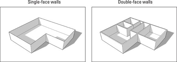
FIGURE 4-1: Use single faces for exterior models and double faces for interior ones.
Making a model that shows both the interior and the exterior of a building at the same time is, to be honest, way too hard. If you need both interior and exterior views, build two separate models instead: one of the interior and one of the exterior. With the two separate models, you can create the combination model in a quarter of the time you took building the first two — we guarantee it.
Starting out in 2D
You can model a building’s interior in lots of ways. In this section, Aidan shares the method he developed over years of creating SketchUp models. Basically, you draw a two-dimensional floor plan that includes all your interior and exterior walls, and then pull it up to the right height (extruded). Only after your model is extruded do you worry about doors, windows, and stairs.
Switching to a 2D view
Before you draw a 2D plan, you need to orient your point of view. Drawing in 2D is easiest when you view your work from directly above, looking down at the ground plane. You also want to make sure that you’re not seeing things in perspective, which distorts your view of what you have.
Follow these simple steps to set up your SketchUp modeling area for 2D drawing:
1. Create a new SketchUp file by choosing File ⇒ New.
Depending on the template you have set to open when you create a new SketchUp file, you may already be in a 2D view. If all you see are the red and green axes on a white background, you can skip Step 2. Remember that you can always switch templates by choosing Help ⇒ Welcome to SketchUp and clicking the Template section of the dialog box that pops up.
2. Choose Camera ⇒ Standard ⇒ Top.
This changes your viewpoint so that you’re looking directly down at the ground.
3. Choose Camera ⇒ Parallel Projection.
Switching from Perspective to Parallel Projection makes it easy to draw plans in 2D. At this point, your modeling window looks like the one shown in Figure 4-2 .
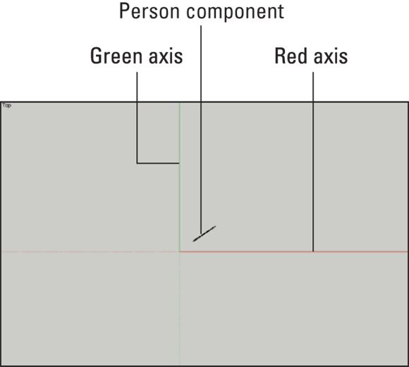
FIGURE 4-2: Your modeling window should look like this before you start drawing in 2D.
Feel free to delete the person component (Chris in 2017, Lisanne in 2016, or in your version of SketchUp, whatever person component appears in every new file). In Top view, the person component is that little diagonal line. To delete the component, just context-click her and choose Erase.
Dusting off SketchUp’s drafting tools
You don’t need many tools to draft a 2D plan in SketchUp. Figure 4-3 shows the basic toolbar; everything you need is right there:
· Line tool: You use the Line tool (which looks like a pencil) to draw edges, which are one of the two basic building blocks of SketchUp models. Fundamentally, you click to start drawing an edge and click again to finish it. (You can find lots more information about drawing lines in Chapter 3 .)
· Eraser tool: Use the Eraser to erase edges, as shown in Figure 4-4 . Although you can’t use the Eraser to delete faces, erasing an edge that defines a face automatically erases that face, too. Take a look at the section about edges and faces at the beginning of Chapter 3 for more detail on using the Eraser tool on edges. You can use the Eraser in two ways:
o Clicking: Click edges to erase them one at a time.
o Dragging: Click and drag over edges to erase them; this is faster if you want to erase lots of edges.
· Circle tool : On the Getting Started toolbar, the Circle tool hides on the Rectangle tool's drop-down menu. Drawing circles in SketchUp is pretty easy: Click once to define the center and again to define a point on the circle (which also defines the radius). To enter a precise radius, just draw a circle, type a radius, and press Enter, as shown in Figure 4-5 . For more information on typing while you draw, check out the section on model accuracy in Chapter 3 .
· Arc tools: As of version 2017, SketchUp has four tools for making arcs (it used to have only one). See Figure 4-6 . Here they are, in order:
o Arc: Click once to define the center point, click again to define the first endpoint, and click a third time to finish the arc. The result is an arc made of straight-edge segments.
o 2 Point Arc: To use this tool, you create a line and pull out a bulge that makes the arc. Click once to define one end, again to define the other end, and a third time to define the bulge. If you want, type a radius after you draw your arc by entering the radius, the units, and the letter r. If you want an arc with a radius of 4 feet, draw it however big, type 4'r , and press Enter.
o ![]() 3 Point Arc: This tool creates an arc around a pivot point. Click to set a start point, click again to set a pivot point, and click a third time to set the arc's endpoint.
3 Point Arc: This tool creates an arc around a pivot point. Click to set a start point, click again to set a pivot point, and click a third time to set the arc's endpoint.
o ![]() Pie: The Pie tool is exactly the same as the Arc tool, but with a useful twist. It yields a pie-shaped face and all three of its perimeter edges.
Pie: The Pie tool is exactly the same as the Arc tool, but with a useful twist. It yields a pie-shaped face and all three of its perimeter edges.
· Offset tool: The Offset tool helps you draw edges that are a constant distance apart from edges that already exist in your model. Pictures are usually better than words, so take a look at Figure 4-7 . Using Offset on the shape creates another shape that’s exactly 6 inches bigger all the way around (middle image), or 6 inches smaller all the way around (right image). Offsetting edges is a useful way to create things like doorways and window trim.
You can use Offset in two ways; for both ways you click once to start offsetting and again to stop:
o Click a face to offset all its edges. If nothing is selected, clicking a face with the Offset tool lets you offset all that face’s edges by a constant amount, as shown in Figure 4-7 .
o Preselect one or more coplanar (on the same plane) edges and then use Offset. If you have selected edges, you can use Offset on just those edges; this comes in handy for drawing things like door frames and balconies, as shown in Figure 4-8 .
· Tape Measure tool: The Tape Measure does a bunch of things. To measure a distance, click any two points in your model. The distance readout is in the Measurements box, in the lower-right corner of your modeling window. You can also use the Tape Measure tool to size a model and to create guides, as we explain in Chapter 3 .
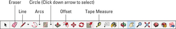
FIGURE 4-3: All the tools you need to draft in 2D in SketchUp are on the basic toolbar.
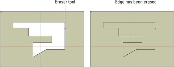
FIGURE 4-4: Use the Eraser tool to erase edges. Erasing an edge that defines a face erases that face, too.
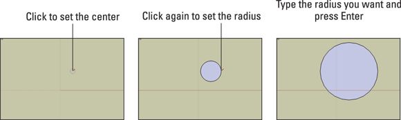
FIGURE 4-5: Drawing circles is easy with the Circle tool.
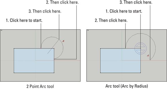
FIGURE 4-6: Using an Arc tool is a three-step operation.
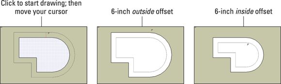
FIGURE 4-7: Offset lets you create edges based on other edges.
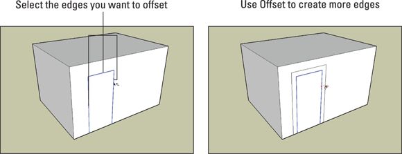
FIGURE 4-8: Using Offset on a set of preselected edges is handy for drawing things like door frames.
Coming up with a simple plan
If all you’re trying to do is model an exterior view of a building, just measure around the actual building’s perimeter, draw the outline of the building in SketchUp, pull it up with the Push/Pull tool, and delete the top face if you like, as shown in Figure 4-9 . Then you can add your desired roof, as explained in “Raising the Roof” later in this chapter. With this method, your walls are only a single-face thick (meaning paper-thin), but that’s okay. You’re only interested in the outside, anyway.
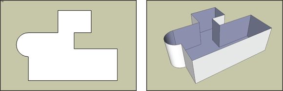
FIGURE 4-9: To make an exterior model, just measure the outside of your building to draw an outline in SketchUp.
Measuring an existing building so that you can model an interior view is easier said than done. Even experienced architects and builders often get confused when trying to model the interiors of as-builts, which are drawings of existing buildings. Closets, ventilation spaces, interior walls, and all kinds of other obstructions inevitably get in the way of good measurements. Usually, you give the measuring your best shot and then tweak things a bit to make them right. The following sections walk you through the process.
Drawing an interior outline
When you model a building's interior, your main goal is creating accurate interior spaces. To achieve that accuracy, work from the inside out. If your tape measure is long enough, measure the major dimensions first. That is, measure the total interior width and length of the building's inside. You may not be able to, but do your best. After that, just work your way around, using basic arithmetic and logic to figure out the size of the space.
Before you start drawing an interior outline in SketchUp, make a paper drawing. The drawing helps you know what you need to draw so you can focus all your concentration for drafting on the computer. Figure 4-10shows the paper sketch that Aidan used when modeling his house.
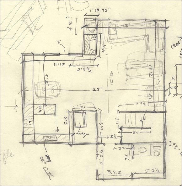
FIGURE 4-10: Aidan's paper sketch.
From this paper drawing, here’s how you draw a basic interior outline of this house:
1. Switch to a 2D overhead view.
The section “Switching to a 2D view ,” earlier in this chapter, explains how.
2. Using the Line tool, draw a line that represents the exact length of a wall in the house.
For example, Aidan starts drawing his house's eastern wall by creating an line that's exactly 17 feet long. (See the top-left image in Figure 4-11 .)
To draw a precise line, click once to start the line, click again to end the line, type 17' , and press Enter. Remember you don’t need to click anywhere before you type a precise value; the Measurements box listens for your keystrokes immediately after you draw something. After you press Enter, the line resizes itself automatically to be exactly 17 feet in length. If you want, you can use the Tape Measure to double-check the size.
3. Connect the next edge to your first one.
As shown in the lower-left image in Figure 4-11 , Aidan works clockwise, drawing an edge 11 feet, 10 inches long, starting at the end of the first edge and heading to the right in the red direction.
4. Keep going all the way around the house, until you get back to where you started. See Figure 4-12 .
![]() If you make a mistake, use the Eraser to get rid of edges. Alternately, undo by pressing Ctrl+Z (⌘+Z on the Mac) or choosing Edit ⇒ Undo to go back a step or two.
If you make a mistake, use the Eraser to get rid of edges. Alternately, undo by pressing Ctrl+Z (⌘+Z on the Mac) or choosing Edit ⇒ Undo to go back a step or two.
5. If all your measurements don’t add up, adjust things so that they do — a few extra inches here and there never killed anyone, after all.
After you complete the outline (forming a closed loop of edges that were all on the same plane), a face automatically appears. Now you have a total of 11 edges and 1 face.
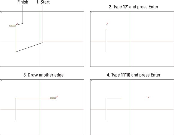
FIGURE 4-11: Start by drawing an edge 17 feet long; then draw a perpendicular edge 11 feet, 10 inches long.
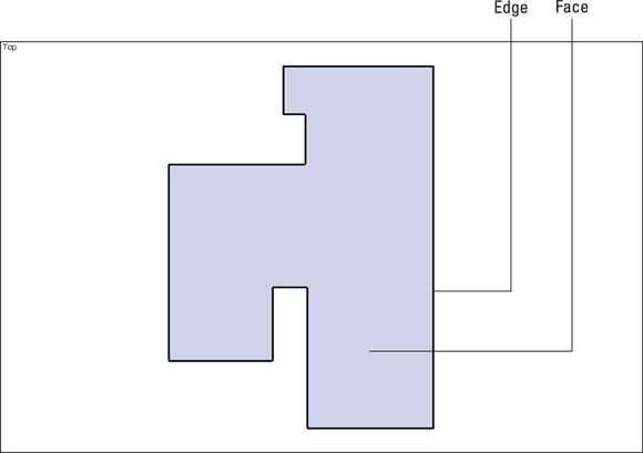
FIGURE 4-12: The completed interior perimeter of Aidan's house.
When you draft in 2D, use only Zoom and Pan to navigate your drawing (see Chapter 3 ). If you accidentally orbit your model into a 3D view, return to 2D by following the steps in the section “Switching to a 2D view,” earlier in this chapter.
If you get lost, and no amount of zooming and panning gets you back to a view of your floor plan, choose Camera ⇒ Zoom Extents or click the Zoom Extents tool. Think of Zoom Extents as an emergency lever you can pull to fill your modeling window with your geometry.
Offsetting and grouping an exterior wall
With the Offset tool, you can offset an exterior wall thickness, which can make it easier to visualize your spaces. Here’s how you do it:
1. ![]() Using the Offset tool, offset your closed shape by 8 inches to the outside. See Figure 4-13 , upper left.
Using the Offset tool, offset your closed shape by 8 inches to the outside. See Figure 4-13 , upper left.
An offset of 8 inches is a pretty standard thickness for an exterior wall, especially for houses in Aidan's neck of the woods. See “Dusting off SketchUp's drafting tools ” earlier in this chapter for details about using the Offset tool. After you create the offset, type 8" and press Enter.
2. Use the Line tool to close off any alcoves, creating pockets of wall that are thicker than the rest. See Figure 4-13 , upper right.
3. With the Eraser tool, delete the extra edges. See Figure 4-13 , middle left.
By deleting the extra edges, you have only two faces: one that represents the floor and one that represents the wall.
4. With the Line tool, draw edges that define the thickness of your exterior wall. See Figure 4-13 , middle right.
For this example, Aidan separated the bulges (which actually represent a fireplace and a mechanical closet) from the part of the wall that goes all the way up to the roof, two stories up.
When you’re done, you end up with several faces: one for the floor, one for the exterior wall (whose thickness should be more or less uniform), and a few for the bulges.
5. Select the face that defines the exterior wall. See Figure 4-13 , lower left.
The easiest way to do this is to click the face with the Select tool.
6. Make the face you just selected into a group. See Figure 4-13 , lower right.
Chapter 5 is all about these groups (and their über-useful cousins, components), but here’s all you need to know for now: Making groups lets you separate different parts of your model. Turning your exterior wall into a separate group makes it easier to edit, hide, and move. Groups also simplify the process of adding more levels to your building, if that becomes necessary.
To turn the face you selected in Step 5 into a group, choose Edit ⇒ Make Group. You see a perimeter of blue lines around your face; that’s the group you just created. Congratulations — you’re now officially an intermediate SketchUp user.
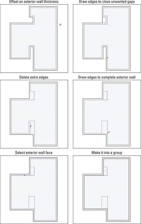
FIGURE 4-13: Use Offset to create an exterior wall thickness and then clean up using the Line and Eraser tools. Finally, make the exterior wall into its own group.
Putting in the interior walls
For this part of the process, guides are your friends. Chapter 3 has a section on guides, where you find a full description of guides and how to use them.
At this point in creating an interior floor plan, Aidan ignores things like doors, windows, and stairs. Where a wall contains a doorway, he draws a solid wall. After you extrude the floor plan into a 3D figure, adding doors, windows, and stairs is much easier.
Working from your 2D drawing, here’s how you create interior walls:
1. ![]() With the Tape Measure tool, create guides to mark the precise location of the interior walls.
With the Tape Measure tool, create guides to mark the precise location of the interior walls.
For example, the guide for the wall in the lower right of the sketch (Figure 4-10 ) is a parallel guide 5 feet, 3½ inches from the inside of the entryway. See Figure 4-14 , left. Figure 4-14 , right, shows all Aidan's guides.
To create a parallel guide, click the edge from which you want to draw the guide, move your cursor (to tell SketchUp which way to go), type your distance (such as 5'3.5 ), and press Enter.
2. With the Line tool, draw edges to represent the interior walls.
With guides, it’s easy to draw your edges correctly. Figure 4-15 shows what you have so far.
Don’t forget to zoom! When you have a jumble of edges and guides and you can’t see what you’re doing, just zoom in. Many folks forget to change their point of view while they work, and zooming makes all the difference.
3. With the Eraser tool, click your guides to delete them.
4. Use the Eraser to delete extra edge segments. See Figure 4-16 .
The goal is to have the smallest-possible number of 2D faces to extrude into 3D walls, a little later on.
Because the exterior-wall face — and the edges that define it — is part of a separate group, accidentally nicking it with the Eraser deletes the whole thing. If this happens, just choose Edit ⇒ Undo to go back a step, zoom in a little bit, and try again.
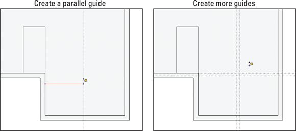
FIGURE 4-14: Draw a guide to help you locate your first interior wall, and then draw a bunch more.
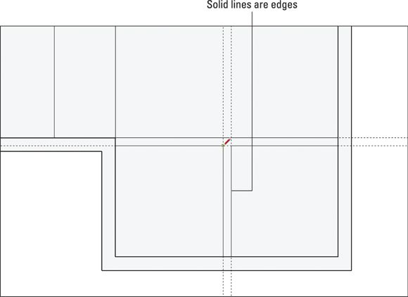
FIGURE 4-15: Use the Line tool to create edges where guides come together.
FIGURE 4-16: Using the Eraser, delete your guides and any little edge segments left over from drawing the interior walls.
Going from 2D to 3D
With a 2D plan in hand, you're ready to extrude it into a 3D model. This process is enormously enjoyable and involves the tool that made SketchUp famous: Push/Pull. In the following sections, you take a simple floor plan (the one you draw earlier in this chapter) and turn it into 3D walls.
Getting a good view
Before you pop up your plan into the third dimension, change your point of view to get a better view of what you’re doing. See Figure 4-17 and follow these steps:
1. Choose Camera ⇒ Perspective.
This turns on SketchUp’s perspective engine, meaning that now you can see things more realistically — the way people really see things in 3D.
2. Choose Camera ⇒ Standard ⇒ Iso.
![]() This switches you from a top view to an isometric (three-quarter) one. You can do this with the Orbit tool, too. SketchUp usually gives you more than one way to do something.
This switches you from a top view to an isometric (three-quarter) one. You can do this with the Orbit tool, too. SketchUp usually gives you more than one way to do something.
3. Choose Camera ⇒ Zoom Extents.
![]() Zoom Extents has its own button on the Getting Started toolbar, but we're sticking with the Camera menu theme, just for consistency.
Zoom Extents has its own button on the Getting Started toolbar, but we're sticking with the Camera menu theme, just for consistency.
4. Choose Camera ⇒ Field of View, type 45, and press Enter.
You’ve changed the field of view from 35 to 45 degrees. By default, SketchUp’s field of view is set to 35 degrees. (For more information on what this means, check out Chapter 11 .)
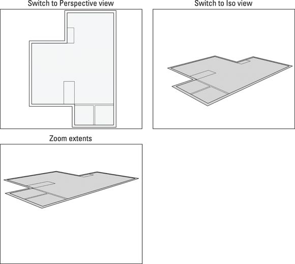
FIGURE 4-17: Before you start work in 3D, switch over to a 3D view.
Pushing/pulling your way to happiness
The Push/Pull tool is a simple creature: It extrudes flat faces into 3D shapes. To use Push/Pull, click a face once to start pushing/pulling it, move your cursor until you like what you see, and then click again to stop pushing/pulling. That’s it. No software tool has ever been so satisfyingly easy to use and understand. For more detail on Push/Pull, see the nearby sidebar, “More fun with Push/Pull .”
Push/Pull works only on flat faces. To edit a curved face, you have to use something else — possibly the Intersect Faces feature.
The following steps outline how to use Push/Pull to extrude an interior floor plan into a 3D model, as shown in Figure 4-18 :
1. Select the Push/Pull tool from the toolbar.
The tool looks like a little box with a red arrow coming out the top.
2. Click an interior wall’s face to start extruding it.
If you click the “floor” face, you’d extrude that instead. If you accidentally choose the wrong face, press Esc to cancel the operation and try again.
3. Move up your cursor to pull up the wall; click to stop extruding.
How much you extrude the face doesn’t matter, because you add precision in the next step.
4. Type a ceiling height (such as 8') and press Enter.
When you do this, the push/pull distance is revised to reflect your exact ceiling height. In this house, that's 8 feet.
5. Repeat Steps 2 through 4 for all the interior walls.
As explained in Chapter 3 , orbiting helps you view what you’re doing as you work around the model.
6. Push/pull the exterior wall to match the height of these interior walls.
Because the exterior wall face is part of a group, you need to “open” the group before you can do anything to it. To open a group, double-click the exterior wall face, or context-click it and choose Edit Group. After you're able to work inside the group, you can follow Steps 2 through 4 in the preceding steps to make the exterior wall group 3D. Click anywhere outside the model to exit the group when you’re done.
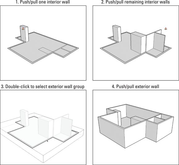
FIGURE 4-18: Push/Pull extrudes faces into the walls of Aidan's house. Presto!
MORE FUN WITH PUSH/PULL
Push/Pull is the tool that most people think of when they think of SketchUp. In fact, the people who invented this software (back in the last millennium) started with the idea for Push/Pull — that’s how closely linked SketchUp and Push/Pull are. If you'd like to know a little more about SketchUp's most distinguished tool, here are five things about Push/Pull that aren’t immediately obvious when you start using it:
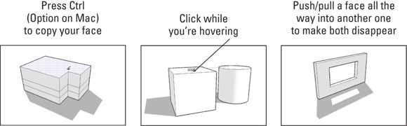
· Double-click with the Push/Pull tool to extrude a face by the last distance you pushed/pulled.
· Press the Ctrl key (Option on a Mac) to push/pull a copy of your face. As shown in the first graphic in the following figure, instead of using Push/Pull the regular way, you can use a modifier key to extrude a copy of the face you’re pushing/pulling. This comes in super-handy for modeling things like multistory buildings quickly.
· While pushing/pulling, hover over other parts of your geometry to tell SketchUp how far to extrude. Take a look at the second graphic. Perhaps you want to use Push/Pull to extrude a cylinder that’s exactly the same height as this box. Before you click the second time to stop pushing/pulling, hover over a point on the top of the box; now the cylinder is exactly that tall. To complete the operation, click while you’re still hovering over the box. It’s pretty simple and saves you hours of time after you’re used to doing it.
· Pushing/pulling a face into another, coplanar face automatically cuts a hole. In fact, this is how you make openings (like doors and windows) in double-face walls. The last graphic shows this in action.
· You can push/pull preselected faces. Push/Pull works just like Move, Rotate, Offset, and Scale: You can preselect a face before you start using the tool. This comes in handy when you need to extrude a face that you can’t see — a rare case, but handy nonetheless.
Adding floors to your building
Adding a second (and third, and fourth) floor to your model isn’t as hard as it may seem. The key is to think of each level as a separate “tray” consisting of interior walls, a floor surface, and the ceiling of the level below. You model each floor as an individual group, making it easier to hide, edit, and move.
For the same reasons, you also make the exterior walls a separate group. They act kind of like a “box” into which your floor levels stack, as shown in Figure 4-19 .
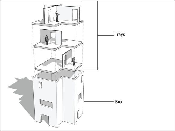
FIGURE 4-19: Floor levels are like trays stacked inside a box consisting of your exterior walls.
Making groups to keep things separate
If you’ve been following along since the beginning of this chapter, the edges and faces that make up your exterior walls are already enclosed in a group by themselves. If they’re not, seriously consider doing that now. If you take the time to group your exterior walls before you add floors to your building, you save hours of headache later. Trust us.
 Otherwise-well-meaning people who have worked with other CAD or 3D modeling programs often take this opportunity to bring layers into the discussion. Yes, SketchUp has a Layers feature. And yes, floor “trays” are a lot like layers, at least conceptually. But you should not use Layers when modeling multiple levels of the same building. Layers in SketchUp simply don’t work the way you might think they do. Chapter 7 explains how SketchUp layers work — and how using them as you would in other programs can make a mess of your 3D model.
If your exterior walls are already a group, the next step is to turn the rest of your first floor’s geometry into another group. This is how you do just that:
1. Select the floor and interior walls of the first level.
You can accomplish this efficiently with the Select tool: Just triple-click a face on any interior wall to select everything that’s attached to it. Chapter 3 has plenty of tips on selecting things.
2. Make a group by choosing Edit ⇒ Make Group from the menu bar.
Chapter 5 is all about groups and components; peruse the first few pages if you’re utterly confused about what just happened.
Drawing the next floor
Modeling each new floor directly on top of the one underneath guarantees that everything in your building lines up. Some folks advocate for working “off to the side” and putting things together later, but Aidan finds that a recipe for trouble. Here’s how you add a second floor to the house model. Check out Figure 4-20 to see the steps as pictures:
1. With the Line tool, trace the inside perimeter of the exterior wall to create a new face.
Keep in mind that tracing works only if everything you touch is already part of another group. If it isn’t, your new edges stick to your existing ones, and your model becomes very, very messy.
2. Push/pull your new face into a thick slab.
How thick? It depends on your building, but a reasonable ceiling-to-floor distance between levels for houses is about 1 foot. You can figure yours out with a tape measure and a calculator.
The underside of the new slab is the ceiling of the first floor. Modeling buildings this way improves visibility because it enables you to hide a floor group to see the one below it.
3. Draw the interior walls of the new floor.
This is just like drawing the first floor. Switch to the Top view (Camera ⇒ Standard Views ⇒ Top) and then use the Tape Measure, Eraser, and Line tools to draft your floor plan. Just start at the very beginning of this chapter for a refresher.
If the floor you’re drawing is bigger than the one below it, its outline overlaps the exterior walls. That’s okay — just pay special attention to where your edges and faces end up as you draw. Orbit every once in a while to check that everything’s copacetic.
In the event that your new floor is smaller than the one underneath, represent the inside boundary of the new exterior walls with a single edge. The next section explains what to do when your first and second floor plans don’t match up exactly.
4. Push/pull your interior walls to the correct height.
That’s 8 feet, in this example.
5. Group together your interior walls, your floor, and the ceiling of the level below.
If you’re unsure of how to do this, take a look at the steps in “Making groups to keep things separate ,” a few pages back.
6. If your upper floor isn’t bigger or smaller than your lower floor, pull up your exterior walls to match your interior ones.
Here you’re extending the box that holds your floor trays up another level. See the last step in “Push/pulling your way to happiness ” earlier in this chapter for details.
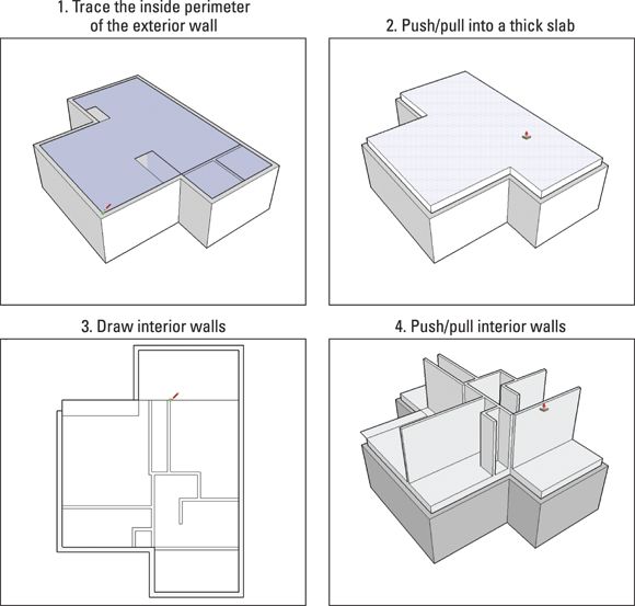
FIGURE 4-20: Draw right on top of the lower floor; then push/pull the interior walls to ceiling height.
Chances are your newest floor doesn’t line up exactly with the one below it. Read the next section to find out what to do. If your building does happen to be one of the few with perfectly aligned floor plans, you can skip the next section entirely. Congrats! You’re a lucky devil.
Creating additional exterior walls
Most buildings aren’t simple extrusions; they bump in and out as they rise. Second-floor decks sit atop first-floor garages; bedrooms cantilever over gardens; intermediate roofs shelter new room additions. Buildings — especially multilevel houses — are complicated assemblies. Figuring out where walls, floors, and ceilings come together takes time, trial and error, and a good dose of spatial reasoning. It’s best not to attempt the steps in this section when you’re tired or distracted.
In the house Aidan models for this chapter, the second floor both overhangs and, um, underhangs (hooray for neologisms) the first floor. Wherever this happens, you need to add a new section of exterior wall, as shown in Figure 4-21 .
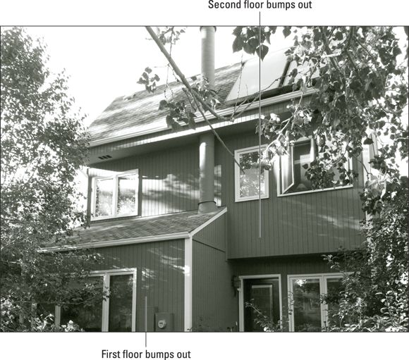
FIGURE 4-21: The outline of the second floor doesn’t exactly match that of the first.
To begin the second floor, draw faces to define any new exterior walls. Follow these steps, which correspond to Figure 4-22 :
1. With the Line tool, trace the inside perimeter of your new exterior walls.
2. Hide the group that includes your second-floor interior walls by context-clicking it and choosing Hide.
You created this group by following the steps in the preceding section, “Drawing the next floor. ”
3. Select the face that you created when you traced the inside perimeter in Step 1.
Don’t see a face? Maybe you forgot to draw an edge somewhere.
4. With the Offset tool, offset the edges of your selected face by the thickness of your exterior walls.
In this case, the thickness is 8 inches.
5. Delete the face in the center, leaving only a face that represents your new exterior wall thickness.
6. Unhide the group you hid in Step 2 by choosing Edit ⇒ Unhide ⇒ Last from the menu bar.
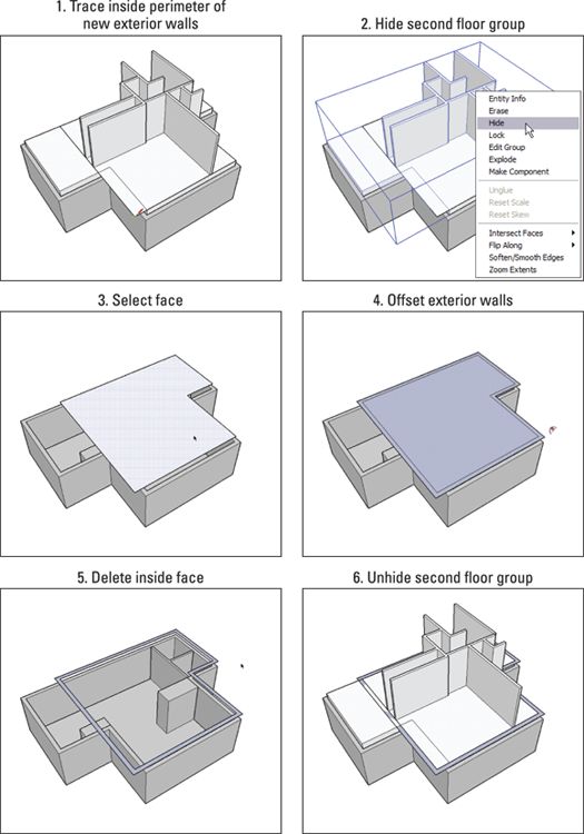
FIGURE 4-22: Use Offset to draw faces that represent new exterior walls.
After you define the exterior wall face, you fine-tune how the second floor rests on top of the first floor by following these steps:
1. Make a group out of your new exterior wall face by selecting it and then choosing Edit ⇒ Make Group.
2. Delete any floor geometry that doesn’t belong.
For example, in Figure 4-23 (top), part of the second floor extends past the exterior wall on the left side of the figure. Double-click the group with the Select tool to edit it, and then use the Eraser to take away only the geometry that doesn’t belong on your new floor, being careful to leave the ceiling that covers the first floor.
3. With the Select tool, double-click the exterior wall face to open the group you created in Step 1.
4. Push/pull down any wall faces to meet the top of the lower floor’s exterior wall. See the bottom of Figure 4-23 .
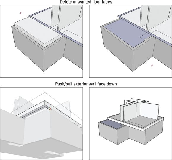
FIGURE 4-23: Delete extra floor faces; then push/pull down the walls.
Only now are you ready to ensconce your second floor in its new exterior walls. Doing so is yet another multistep process:
1. Make all your exterior walls part of the same group:
1. Select the group that contains your new exterior walls and then choose Edit ⇒ Cut.
2. With the Select tool, double-click the group containing your lower exterior walls.
You’re “inside” that group.
3. Choose Edit ⇒ Paste in Place.
4. Choose Edit ⇒ Group ⇒ Explode to ungroup the edges and faces in the selected group, sticking them to those in the lower group.
Whew.
2. With the Line tool, add any necessary edges. With the Eraser tool, delete any extraneous ones.
In Figure 4-24 , you can see where the model has extra edges that need to be deleted.
Using your SketchUp virtuosity, watch the colors as you draw, use the Shift key to lock inferences, and remember to zoom in on what you’re doing. Skimming Chapter 3 provides useful pointers on these actions.
3. With the Push/Pull tool, extrude your exterior walls up to the height of your second-floor interior walls (also shown in Figure 4-24 ).
4. Orbit around your model to make sure all is well.
You can see the result in the lower right of Figure 4-24 .
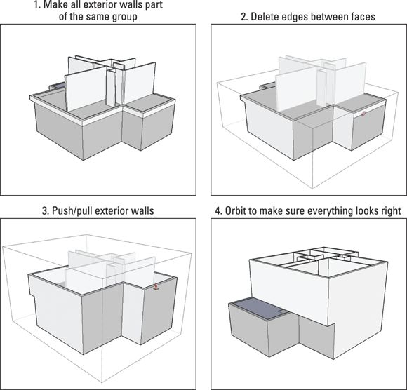
FIGURE 4-24: Do what you need to do to make your exterior walls look right.
Up, up, and away
Now that you’re privy to Aidan's favorite technique for modeling multilevel buildings, you can build up as high as you like. As you proceed, the following tidbits may be helpful:
· Hide things to get a clearer view for your current task. When you context-click any entity and choose Hide, it’s often easier see what you’re doing. This is particularly true of groups, which is why, in the steps in the preceding sections, you to go to so much trouble to create those groups. To see stuff that’s hidden, choose View ⇒ Hidden Geometry. To unhide something that’s hidden, context-click and choose Unhide.
· Better yet, use the Outliner. Chapter 7 is all about making your SketchUp life easier by using certain tools to work more efficiently. If you’re up for it, skip ahead and read the stuff about the Outliner. It’s hyper-relevant to staying organized and seeing what's where as you create a multilevel building.
· There’s gold in Model Info. Choose Window ⇒ Model Info and then click the Components option on the left. Next to the Fade Rest of Model slider, you can select a Hide check box. With this check box selected, everything outside the group you’re currently editing becomes hidden. Smart modelers (such as yourself) make liberal use of this gem when cutting doors and windows in interior walls, which is the topic of the next section.
Inserting doors and windows
To add doors and windows, the best method depends on what kind of building you’re modeling, whether you’re using single-face or double-face walls, and how much detail you plan to include in your model. You can make openings in your walls in a couple ways:
· Cut openings with SketchUp components. The SketchUp 3D Warehouse (read all about it in Chapter 5 ) contains scores of doors and windows that you can download and use in your models. Some of them cut their own openings when you insert them in a face. Here’s the catch, though: SketchUp’s cut-opening components work only on single-face walls, which means that they’re only really useful for exterior building models. If you’re building an interior model, you have to cut your own openings.
· Cut openings yourself. For double-face walls, this is your only option; luckily, it’s easy to do. Basically, draw the opening’s outline and then use Push/Pull to create the opening. The process is the same for doors and windows.
Using SketchUp’s handy-dandy components
As long as you’re making an exterior model, you can use the door and window components from SketchUp’s 3D Warehouse. Without going into a ton of detail, here’s what you need to know about them:
· Components are accessible from the Components panel. The Components panel appears on the Default Tray, but if you don't see it, check whether Components is selected on the submenu that appears when you choose Window ⇒ Default Tray. On the Components panel, click the drop-down menu next to the In Model icon and select Architecture, which contains the Doors, Windows, and DC Doors and Windows collections. Components that can cut their own openings generally contain gluing or cutting in their descriptions. Keep in mind that you need to be online to access the 3D Warehouse.
· You can find hundreds more online. If you’re connected to the Internet, you can type any search query (such as revolving door ) into the little search box at the top of the Components panel. This scours the 3D Warehouse for your search term and shows the results below. Some advice: The 3D Warehouse holds so much stuff that making your query specific helps you sort through the results.
· Components are editable. You find details in Chapter 5 , but here’s the gist: If you don’t like something about a component you find online, you can change it.
· Some components are dynamic. Dynamic Components have special capabilities that make them easier to resize and otherwise reconfigure. You can read all about Dynamic Components in Chapter 5 .
· When components cut their own openings, the openings aren’t permanent. When you move or delete a hole-cutting door or window component you’ve placed in a model, the opening goes with the component.
Follow these steps to add a door or window component to your model:
1. With the Tape Measure tool, create guides to help you line up your doors or windows.
Guides are the best way to ensure that everything’s in the right spot. In Figure 4-25 , two horizontal guides (which are 2.5 feet from the bottom of the exterior wall) mark where to place the bottom of the windows. One vertical guide marks where to place the right edge of the door. After Rebecca placed the door, she created a guide 4 feet from each side of the door, to help place the windows symmetrically. Chapter 3 explains how to create guides.
2. In the Components panel, select the component that you want to place in your model.
For help navigating the Components panel, see Chapter 5 .
3. In the drawing area, click to place the component where you want it to be.
In Figure 4-25 , you see one door and four instances of the window component.
4. If you don’t like where your component is, use the Move tool (read all about it in Chapter 3 ) to reposition your component.
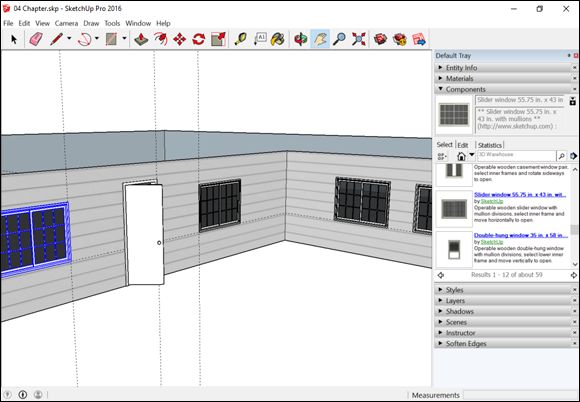
FIGURE 4-25: Placing window and door components in your model is a breeze.
Making your own openings
Most of the time, you can’t get away with using SketchUp’s built-in door and window components. Because these components can’t cut through two-faced walls, they’re limited to external use only. That’s okay though; cutting your own holes in walls is quick and easy, and you end up with exactly what you want.
To cut a precise opening in a double-face wall, here’s what you need to do; Figure 4-26 shows the basic steps:
1. Mark where you want your opening to be with guides.
For a refresher on using guides, have a look at Chapter 3 .
If you’re drawing on a wall that’s part of a group, you need to edit that group in order to punch holes in the wall. To edit a group, double-click it with the Select tool. To stop editing, click somewhere off to the side of your model. Chapter 5 has more info about working with groups.
2. Draw the outline of the opening you want to create, making sure to create a new face in the process.
Use the Line tool, and keep an eye out for the colored inferences, which let you know where you are.
3. With the Push/Pull tool, extrude your new face back into the thickness of the wall until it touches the face behind it.
If everything goes well, your face disappears, taking with it the corresponding area of the face behind it. Now you have an opening in your wall. If your face doesn’t disappear, and no opening is created, it’s probably for one of the following reasons:
o Your faces aren’t parallel to each other. This technique works only if both faces are parallel. Keep in mind that just because two faces look parallel doesn’t mean that they are.
o You hit an edge. If you push/pull your face into a face with an edge crossing it, SketchUp gets confused and doesn’t cut an opening. Use Undo, get rid of the pesky edge (if you can), and try again.
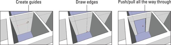
FIGURE 4-26: With guides and the Push/Pull tool, create an opening through parallel faces.
Don’t forget to orbit! If you can’t quite push/pull what you mean to push/pull, orbit around until you can see what you’re doing.
Staring Down Stairs
You can make stairs probably a million different ways in SketchUp, and in the following sections, you find two methods that work equally well.
Chapter 5 contains a third, slightly trickier (but way more powerful) way of making stairs using components. SketchUp’s Dynamic Components have some pretty neat implications for models that need stairs. A so-called dynamic stair component automatically adds or subtracts individual steps as you make it bigger or smaller with the Scale tool. Depending on what you want to accomplish, a premade dynamic stair component may save you a bunch of time. Find out more about them in Chapter 5 .
Before you dive in, here’s some simple stairway vocabulary, just in case you need it. Figure 4-27 provides a visual reference:
· Rise and run: The rise is the total distance your staircase needs to climb. If the vertical distance from your first floor to your second (your floor-to-floor distance) is 10 feet, that’s your rise. The run is the total horizontaldistance of your staircase. A set of stairs with a big rise and a small run would be really steep.
· Tread: A tread is an individual step — the part of the staircase you step on. When someone refers to the size of a tread, he’s talking about the depth — the distance from the front to the back of the tread. Typically, this is anywhere from 9 to 24 inches, but treads of 10 to 12 inches are most comfortable to walk on.
· Riser: The riser is the part of the step that connects each tread in the vertical direction. Risers are usually about 5 to 7 inches high, but that depends on your building. Not all staircases have actual risers (think of steps with gaps between treads), but they all have a riser height.
· Landing: A landing is a platform somewhere around the middle of a set of stairs. Landings are necessary in real life, but modeling them can be a pain; figuring out staircases with landings is definitely more complicated. Sometimes, modeling a landing is easier if you think of it as a really big step.
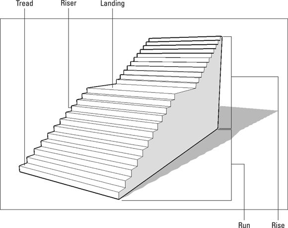
FIGURE 4-27: The anatomy of a staircase.
Model steps as a group, separate from the rest of your building, and move them into position when they’re done. You can read all about groups in Chapter 5 .
The Subdivided Rectangles method
The Subdivided Rectangles method is how most people think to draw their first set of stairs. This method is intuitive and simple, but a bit more time-consuming than the other methods in this book.
The key to the Subdivided Rectangles method is a special trick you can do with edges: Called Divide, it lets you pick any edge and divide it into as many segments as you want. If you know how many steps you need to draw but not how deep each individual tread needs to be, the Divide command comes in really handy.
Here’s how the Subdivided Rectangles method works. See Figure 4-28 :
1. Draw a rectangle the size of the staircase you want to build.
2. With the Select tool, context-click a long edge of your rectangle and choose Divide.
If your staircase is wider than it is long, context-click a short edge instead.
3. Before you do anything else, type the number of treads you want to create and press Enter.
This command automatically divides your edge into many more edges, eliminating the need to calculate how deep each of your treads needs to be. Essentially, each new edge becomes a side of one of your treads.
4. Draw a line from the endpoint of each new edge, dividing your original rectangle into many smaller rectangles.
You can use the Line or the Rectangle tool to do this.
5. From one of the corners of your original rectangle, draw a vertical edge that's the height of your staircase’s total rise.
6. Use the Divide command to split your new edge into however many risers you need in your staircase (generally your number of treads, plus one).
Repeat Steps 2 and 3 to do this. The endpoints of your new, little edges tell you how high to make each step.
7. Push/pull the rectangle that represents your last step to the correct height.
Here’s where you need to use the hover-click technique that we describe in the sidebar “More fun with Push/Pull ,” earlier in this chapter. Just click once to push/pull, hover over the endpoint that corresponds to the height of that tread, and click again. Your step is automatically extruded to the right height.
Extrude your highest step first, but remember that it doesn’t go all the way to the top. You always have a riser between your last step and your upper floor.
8. Repeat Step 7 for each remaining step.
9. Use the Eraser to eliminate extra edges you don’t need.
Don’t accidentally erase geometry on the part of your staircase you can’t see. Turning on Back Edges (View ⇒ Edge Style ⇒ Back Edges) is a nice way to see “through” your model without resorting to X-Ray mode.
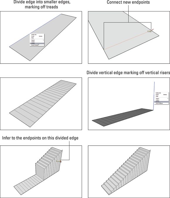
FIGURE 4-28: The Subdivided Rectangles method of building stairs.
The Copied Profile method
This method for modeling a staircase relies, like the last one, on using Push/Pull to create a 3D form from a 2D face, but this method is more elegant. In a nutshell, draw the profile — the side view, sort of — of a single step and then copy as many steps as you need, create a single face, and extrude the whole thing into shape. The first time you do this is breathtakingly satisfying — one of those “guaranteed to make you smile” SketchUp operations you’ll want to repeat for friends (assuming you have nerdy friends like us).
Follow these steps to make a staircase using the Copied Profile method, as shown in Figure 4-29 :
1. Start with a large, vertical face; make sure that it’s big enough for the flight of stairs you want to build.
You’re going to end up pushing/pulling the whole shebang out of the side of this face, just so you know.
2. In the bottom corner of the face, draw the profile of a single step.
The Line tool is a great choice, although you may want to use an arc or two, depending on the level of detail you need. For a refresher on drawing lines accurately, check out Chapter 3 .
3. Select all the edges that make up your step profile.
You can hold down the Shift key while clicking with the Select tool to select multiple entities. Chapter 3 has lots of selection tips.
4. Make a copy of your step profile and place it above your first one.
If you’re unfamiliar with how to make copies using the Move tool, see Chapter 3 .
5. Type the number of steps you want to make, type x , and then press Enter.
For example, if you want ten steps, type 10x . This technique repeats the copy operation you just did by however many times you tell it to; the x after the number tells SketchUp to make copies.
6. If you need to, draw an edge to make sure that all your step profiles are part of a single face.
7. Push/pull the staircase face to reflect the desired width of your staircase.
This part seems like magic to most folks; we don’t think it ever gets old.
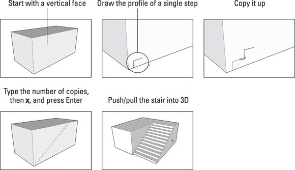
FIGURE 4-29: The Copied Profile method.
This method of stairway building also works great in combination with the Follow Me tool, covered in Chapter 6 . Figure 4-30 whets your appetite. Follow Me is cool beans, all the way around.
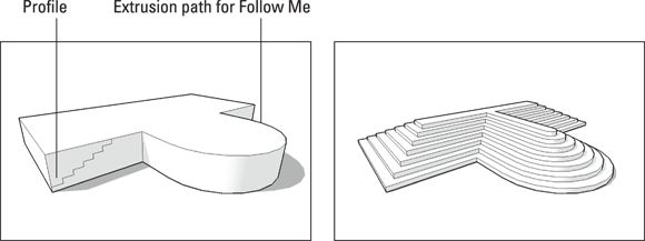
FIGURE 4-30: Using Follow Me with the Copied Profile method produces some impressive geometry, indeed.
Raising the Roof
If you’re lucky, the roof you want to build is fairly simple. Unfortunately, home builders sometimes go a little crazy, creating roofs with dozens of different pitches (slopes), dormers, and other doodads that make modeling them a nightmare. For this reason, this section keeps things pretty simple: The following sections show you how to identify and model basic roof forms. After that, you discover a great tool — Intersect Face — that you can use to assemble complicated roofs from less-complicated pieces.
The tricky thing about roofs is that they’re hard to see. If you want to make a model of something that already exists, it helps to get a good look at it — but that’s not always possible with roofs. Google Maps offers a neat way to view an existing roof you’re trying to build.
Always, always make a group out of your whole building before you work on your roof. If you don’t, your geometry starts sticking together, you end up erasing walls by accident, and eventually, you lose your mind. On top of that, the ability to separate your roof from the rest of your building whenever you want is handy. You can also group your roof, if that makes sense for what you’re doing. Check out Chapter 5 for a full rundown on making and using groups.
Before you dive in, here's a brief guide to general roof types and terminology that may come in handy for the explanations later in this chapter. Figure 4-31 illustrates each of the following terms:
· Flat roof: Flat roofs are just that, except they aren’t — if a roof were really flat, it would collect water and leak. That’s why even roofs that look flat are sloped very slightly.
· Pitched roof: Any roof that isn’t flat is technically a pitched roof.
· Shed roof: A shed roof is one that slopes from one side to the other.
· Gabled roof: Gabled roofs have two planes that slope away from a central ridge.
· Hip roof: A hip roof is one where the sides and ends all slope in different directions.
· Pitch: The angle of a roof surface.
· Gable: A gable is the pointy section of wall that sits under the peak of a pitched roof.
· Eave: Eaves are the parts of a roof that overhang the building.
· Fascia: Fascia is the trim around the edge of a roof’s eaves where gutters are sometimes attached.
· Soffit: A soffit is the underside of an overhanging eave.
· Rake: The rake is the part of a gabled roof that overhangs the gable.
· Valley: A valley is formed when two roof slopes come together; this is where water flows when it rains.
· Dormer: Dormers are the little things that pop up above roof surfaces. They often have windows and make attic spaces more usable.
· Parapet: Flat roofs that don’t have eaves have parapets — extensions of the building’s walls that go up a few feet past the roof itself.
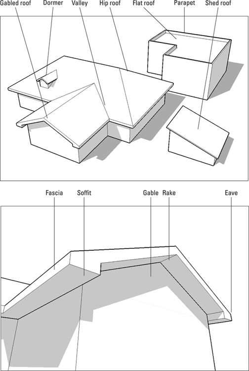
FIGURE 4-31: Some different kinds of roofs, and their various and sundry parts.
Building flat roofs with parapets
Good news! SketchUp was practically made for modeling these kinds of roofs. By using a combination of the Offset tool and Push/Pull, you can make a parapet in less than a minute. Follow these steps, as shown in Figure 4-32 :
1. With the Offset tool, click the top face of your building.
2. Click again somewhere inside the same face to create another face.
3. Type the thickness of your parapet and then press Enter.
This redraws your offset edges to be a precise distance from the edges of your original face. How thick should your parapet be? It all depends on your building, but most parapets are between 6 and 12 inches thick.
4. Push/pull your outside face (the one around the perimeter of your roof) into a parapet.
5. Type the height of your parapet and then press Enter.
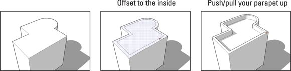
FIGURE 4-32: Modeling parapets on flat-roofed buildings is easy.
PITCHED ROOFS CAN MAKE YOU CRAZY
That fact notwithstanding, a few tips might make building your next pitched roof a little easier:
· Start by making the rest of your building a group. As we warn you elsewhere in this section, you should always make a group out of your whole building before you start working on your roof.
· Draw a top view of your roof on paper first. Working out the roof's basic shape in your mind can help you figure out how to manage the roof's details. Adding measurements and angles is even better because these details help you know what to do in SketchUp.
· Figure out how to use the Protractor tool. This tool (which is on the Tools menu) is for measuring angles and, more importantly, creating angled guides. Because sloped roofs are all about angles, you probably need to use the Protractor sooner or later. To find out how this tool works, open the Instructor panel and then activate the Protractor tool. Chapter 3 's section on rotating can also help you, because, in many ways, the Protractor tool behaves like the Rotate tool.
Creating eaves for buildings with pitched roofs
Aidan's favorite way to create eaves, or roof overhangs, is to use the Offset tool. Follow these steps to get the general idea and see Figure 4-33 :
1. Make a group out of your whole building before you start modeling the roof.
Keeping your roof separate makes your model easier to work with.
2. With the Line tool, create an outline of the parts of your roof that will have eaves of the same height.
The goal is a single face that you can offset. A lot of buildings have complex roofs with eaves of all different heights; for the sake of this step, just create a face that, when offset, will create roof overhangs in the right places.
3. With the Offset tool, create an overhanging face.
For instructions on how to use Offset, see the section “Dusting off SketchUp’s drafting tools ,” earlier in this chapter.
4. Erase the edges of your original face.
Here’s a quick way to do this with the Select tool:
1. Double-click inside your first face.
This selects both the face and the edges that define it.
2. Press Delete to erase everything that’s selected.
5. Push/pull your overhanging roof face to create a thick fascia.
Different roofs have fasciae of different thicknesses; if you don’t know yours, just take your best guess.
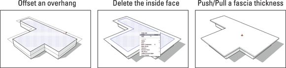
FIGURE 4-33: Eaves are the parts of the roof that overhang a building’s walls.
Constructing gabled roofs
You can construct a gabled roof in a bunch of ways (every SketchUp expert has her favorite), but one method works particularly well.
Follow these steps to build a gabled roof, which is shown in Figure 4-34 :
1. Create a roof overhang, following the steps in the preceding section.
Most gabled roofs have eaves, so you probably need to create them for your building.
2. With the Protractor tool, create an angled guide at the corner of your roof.
The nearby sidebar, “Pitched roofs can make you crazy ,” points you to help with the Protractor.
 Architects and builders often express angles as rise over run ratios. For example, a 4:12 (pronounced 4 in 12 ) roof slope rises 4 feet for every 12 feet it runs. A 1:12 slope is very shallow, and a 12:12 slope is very steep. When you are using the Protractor tool, SketchUp’s Measurements box understands angles expressed as ratios as well as those expressed in degrees. Typing 6:12 yields a slope of 6 in 12.
3. With the Line tool, draw a vertical edge from the midpoint of your roof to the angled guide you created in Step 2.
The point at which your edge and your guide meet is the height of your roof ridge.
4. Draw two edges from the top of your vertical line to the corners of your roof.
This creates two triangular faces.
5. Erase the vertical edge you drew in Step 3 and the guide you drew in Step 2.
6. Push/pull back your triangular gable.
If your gabled roof extends all the way to the other end of your building, push/pull it back that far. If your roof runs into another section of roof, as shown in Figure 4-35 , extrude it back until it’s completely “buried.” The section “Sticking your roof together with Intersect Faces ,” later in this chapter, has more information on how to make a complex roof.
7. Finish your eaves, fascia, soffit, and rake(s) however you want.
Gabled roofs have more details than we can cover, but Figure 4-36 shows a few common ones.
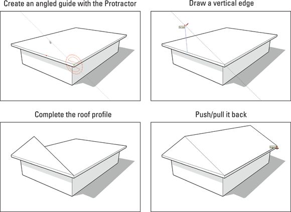
FIGURE 4-34: Gabled roofs are relatively easy to make in SketchUp.
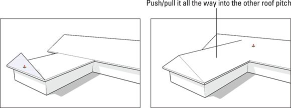
FIGURE 4-35: If your gabled roof is part of a larger roof structure, it may just run into another roof pitch. Let it.
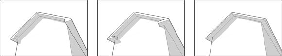
FIGURE 4-36: Some common gabled roof details.
Making hip roofs
Believe it or not, building a hip roof is easier than building a gabled one. Hip roofs don’t have rakes, which makes them a lot less complicated to model. Follow these steps to find out for yourself:
1. Follow Steps 1 through 5 in the preceding section “ Constructing gabled roofs .”
2. Measure the distance from the midpoint of the gable to the corner of the roof.
Because hip roofs have pitches that are the same on all sides, you can use a simple trick to figure out where to locate the hip in your roof. It’s a lot easier than using the Protractor.
3. With the Tape Measure, create a guide the distance you just measured from the end of the gable, as shown in Figure 4-37 .
4. Draw edges from the point on the ridge you just located to the corners of your roof, as shown in Figure 4-37 .
This does two things: It splits the sides of your roof into two faces each and creates a new face (which you can’t see yet) under the gabled end of your roof.
5. Erase the three edges that form the gabled end of your roof, revealing the “hipped” pitch underneath.
Neat, huh? Now all three faces of your roof are the same pitch — just the way they should be.
6. If appropriate, repeat the process on the other end of your roof.
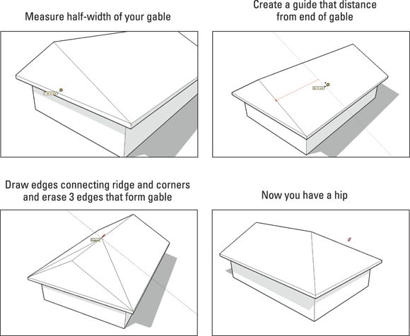
FIGURE 4-37: To make a hip roof, start with a gabled one.
Sticking your roof together with Intersect Faces
In general, the newer and more expensive a house is, the more roof slopes it has. Who knows why this is the case? Maybe folks think complex-roofed houses look more like French chateaus. Whether crazy roofs are a good thing isn’t relevant to this book, but they’re a pain in the, um, gutters to model.
Luckily, SketchUp has a relatively little-known feature that often helps when it comes to making roofs with lots of pitches: Intersect Faces. Here’s what you need to know about this terrific little tool:
· Intersect Faces makes new geometry from existing geometry. It takes faces you’ve selected and creates edges wherever they intersect. Figure 4-38 shows what we mean: Perhaps you want to make a model that’s a cube with a cylinder-shaped chunk taken out of it. You’d model the cube and model the cylinder. After positioning them carefully, you can then use Intersect Faces to create edges where the two shapes’ faces come together. After that, the Eraser can remove the edges you don't want — the rest of the cylinder, in this case.
· Intersect Faces and the Eraser tool go hand in hand. Anytime you use Intersect Faces, you need to follow up by deleting unwanted geometry. To find it all, orbit, zoom, and pan around your model, zapping stray lines and faces with the Eraser as you go.
· Most of the time, choose Intersect Faces with Model. This tool has three modes, but the majority of the time, you use the basic one. Here’s what all three modes do:
o Intersect Faces with Model: Creates edges everywhere your selected faces intersect with other faces in your model — whether the other faces are selected or not.
o Intersect Faces with Selection: Only creates edges where selected faces intersect with other selected faces. This is handy if you’re trying to be a little bit more precise.
o Intersect Faces with Context: Choosing this option creates edges where faces within the same group or component intersect; that’s why it’s available only when you edit a group or component.
· Intersect Faces doesn’t have a button. To use it, you have to either
o Context-click and choose Intersect Faces.
o Choose Edit ⇒ Intersect Faces.
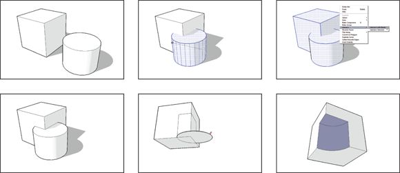
FIGURE 4-38: Using Intersect Faces to cut a partial cylinder out of a cube.
When creating roofs, you can use Intersect Faces to combine a whole bunch of gables, hips, dormers, sheds, and so on into a single roof. Doing so is no cakewalk, and it requires a fair amount of planning, but it works great when nothing else will.
Figure 4-39 shows a complicated roof with several elements. Gabled roofs have been pushed/pulled into the main hip roof at all different heights, but edges don’t exist where all the different faces meet. In the steps that follow, use Intersect Faces to create the edges you want and then use the Eraser to clean up the mess:
1. Select the whole roof.
If you grouped your building and roof the way we recommend earlier in this chapter, here's a timesaving trick: Hide the group that contains the rest of your building and then draw a big selection box around the whole roof with the Select tool.
2. Choose Edit ⇒ Intersect Faces ⇒ With Selected.
This tells SketchUp to create edges everywhere faces intersect — that is, everywhere faces pass through each other without an edge.
3. With the Eraser, carefully delete the extra geometry on the inside of your roof, as shown in Figure 4-39 .
Although this erasing can be a lot of work, it’s a whole lot easier than using the Line tool and SketchUp’s inference engine to figure out where complex roof details should go.
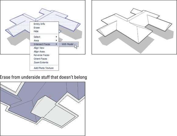
FIGURE 4-39: Here’s a typically complex roof that Intersect Faces can unify.
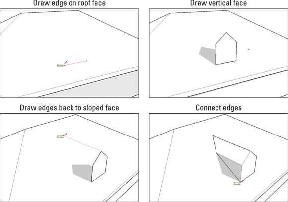
WHEN ALL ELSE FAILS, USE THE LINE TOOL
Fancy tools like Follow Me and Intersect Faces are useful most of the time, but for some roofs, you just have to resort to drawing good old edges. If that’s the case, you’d better get familiar with most of the stuff at the beginning of Chapter 3 because you’re going to be inferencing like there’s no tomorrow. SketchUp users who really know what they’re doing can draw anything with the Line and Eraser tools, which is beautiful to watch but beyond the scope of this book.
All the same, the following figure shows how the Line tool and SketchUp’s venerable inference engine help you draw a gabled dormer on a sloped roof surface. With practice, you can do it.
All materials on the site are licensed Creative Commons Attribution-Sharealike 3.0 Unported CC BY-SA 3.0 & GNU Free Documentation License (GFDL)
If you are the copyright holder of any material contained on our site and intend to remove it, please contact our site administrator for approval.
© 2016-2026 All site design rights belong to S.Y.A.