SketchUp For Dummies (2017)
Part 2
Modeling in SketchUp
Chapter 6
Going Beyond Buildings
IN THIS CHAPTER
![]() Extruding around circles and along paths with Follow Me
Extruding around circles and along paths with Follow Me
![]() Mastering the Scale tool
Mastering the Scale tool
![]() Creating 3D terrain with the Sandbox tools
Creating 3D terrain with the Sandbox tools
![]() Using the Solid Tools for additive and subtractive modeling
Using the Solid Tools for additive and subtractive modeling
Here’s something you already know: There’s more to life than modeling buildings. Even though SketchUp is really good at letting you make models of built structures, you can use SketchUp to build just about anything you can imagine. All you need is time, ingenuity, and the ability to step back and break down things into their basic parts. SketchUp provides fantastic tools for creating forms that aren’t the least bit boxy, but those tools aren’t as obvious as Push/Pull and Rectangle, so most people never find them. This chapter is devoted to helping you discover SketchUp’s “rounder” side.
Another reason for pushing past basic boxes? Many people see 3D printing (sound of futuristic music and warp drives engaging) as the next vanguard of human innovation, and 3D modeling — like you do with SketchUp — is half of that equation. If you’re going to be printing your own bike helmets and vacuum cleaners in the next decade, you’d better get good at modeling organic shapes. (Chapter 9 offers an introduction to 3D printing with SketchUp.)
In this chapter, you discover tools, techniques, and other tips for creating forms that are distinctly unbuilding-like. Our hope is that you’ll use them to push the limits of what you think SketchUp can do.
Extruding with Purpose: Follow Me
Follow Me is probably the best example of a powerful SketchUp tool with kind of an underwhelming name. When the software designers were trying to figure out what to call their new baby, the problem that they faced was this: This tool does what other 3D modeling programs dedicate two or three other tools to doing. The designers chose an unconventional name because Follow Me is a wholly unconventional tool.
As shown in Figure 6-1 , you can use Follow Me to create all sorts of shapes:
· Bottles, spindles, and spheres: These are all examples of lathed forms. You can create these by spinning a 2D profile (shape) around a central axis to create a 3D model.
· Pipes, gutters, and moldings: If you look closely, all three of these things are basically created by extruding a 2D face along a 3D path; the result is a complex 3D form.
· Chamfers, fillets, and dados: Without explaining what all these things are (that’s what Internet search engines are for), know this: You can use Follow Me to cut away profiles, too.
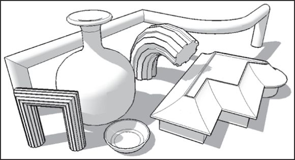
FIGURE 6-1: Follow Me lets you create all kinds of different shapes.
Using Follow Me
At its core, Follow Me lets you create forms that are extrusions. It’s a little bit like Push/Pull, except that it doesn’t just work in one direction. You tell Follow Me to follow a path, and it extrudes a face all along that path. So, you need three things to use Follow Me:
· A path: In SketchUp, you can use any edge, or series of edges, as a path. All you have to do is make sure that they’re drawn before you use Follow Me.
· A face: Just like with Push/Pull, Follow Me needs a face to extrude. You can use any face in your model, but the face needs to be created before you start using Follow Me.
· Undo: Imagining what a 2D face will look like as a 3D shape isn’t easy. Getting a Follow Me operation right usually takes a couple tries. That’s what Undo is for, after all.
Follow these steps to use Follow Me; Figure 6-2 shows a basic example of how it works:
1. Draw a face to use as an extrusion profile.
In this example, you create a pipe, so the extrusion profile is a circular face.
2. Draw an edge (or edges) to use as an extrusion path.
Although the edge (or edges) is touching the face in this case, it doesn’t have to for Follow Me to work.
3. Select the complete extrusion path you want to use.
Check out the section on making selections in Chapter 3 for pointers on using the Select tool to best advantage.
4. ![]() Activate the Follow Me tool by choosing Tools ⇒ Follow Me.
Activate the Follow Me tool by choosing Tools ⇒ Follow Me.
To see Follow Me on your toolbar, select the Large Tool Set. On Windows, choose View ⇒ Toolbars, select the Large Tool Set check box in the dialog box that appears, and click Close. On a Mac, choose View ⇒ Tool Palettes ⇒ Large Tool Set.
5. Click the face you want to extrude.
Magic! Your face (extrusion profile) is extruded along the path you chose in Step 3, creating a 3D form (in this case, a section of pipe).
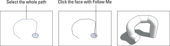
FIGURE 6-2: Using Follow Me to create a simple extruded shape.
 If you want to use Follow Me all the way around the perimeter of a face, you don’t need to spend time selecting all the individual edges. Just select the face and then use Follow Me; the tool automatically runs all the way around any selected face.
 You can use Follow Me another way, too: Instead of preselecting a path (as in Step 3 of the preceding list), you can click any face with Follow Me and attempt to drag it along the edges in your model. Although this dragging method works on simple things, preselecting a path works a lot better — it’s really the only option for using Follow Me in a predictable way.
Making lathed forms like spheres and bottles
And nuclear power plant chimneys. A surprising number of things can be modeled by using Follow Me to perform a lathe operation. A lathe is a tool that carpenters (and machinists) use to spin a block of raw material while they carve into it — that’s how baseball bats are made (the good ones, anyway).
A simple example of a lathed object is a sphere. Here’s how you might make one with Follow Me:
1. Draw a circle on the ground.
2. Rotate a copy of your circle by 90 degrees, as shown in Figure 6-3 .
If you’re wondering how to do this, follow these steps:
1. ![]() Select the face of your circle with the Select tool and then choose Tools ⇒ Rotate to activate the Rotate tool.
Select the face of your circle with the Select tool and then choose Tools ⇒ Rotate to activate the Rotate tool.
2. Press the Ctrl key (Option on a Mac) to tell SketchUp you want to make a copy.
3. Click a green endpoint inference along the edge of your circle and hold down your mouse button to drag. Don’t let go just yet.
4. Still dragging, move your cursor to the endpoint on the exact opposite side of your circle; then release your mouse button.
Your axis of rotation is a line right through the center of your circle.
5. Click anywhere on the edge of your circle and then move your mouse over a little bit.
6. Type 90 and press Enter.
You can read all about the Rotate tool in Chapter 3 .
3. Make sure that one of your circles is selected.
4. With the Follow Me tool (choose Tools ⇒ Follow Me), click the circle that’s not selected, as shown in Figure 6-4 .
Now you have a sphere. The Follow Me tool lathed your circular face around the path you selected — the other circle.
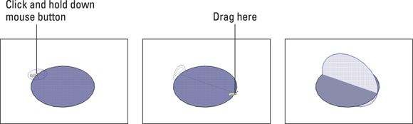
FIGURE 6-3: Using the Rotate tool to make a rotated copy of a circle.
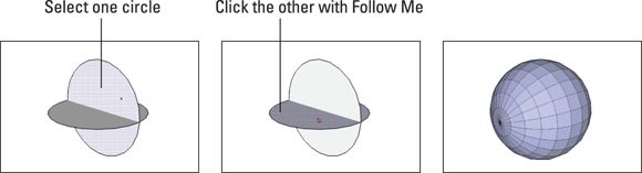
FIGURE 6-4: Clicking one circle with Follow Me while the other one is selected produces a sphere.
If you really need a sphere, the easiest way to get one is in the Components panel. Type sphere into the 3D Warehouse search box, and then press Enter on your keyboard. Something useful should appear.
If you want to make your curved surfaces look smooth (hiding the edges between them), check out the sidebar “Smoothing those unsightly edges ,” later in this chapter.
Under typical circumstances, you only have to model half a profile to use Follow Me to make it three-dimensional. Figure 6-5 shows a few examples of 3D objects created by using Follow Me.
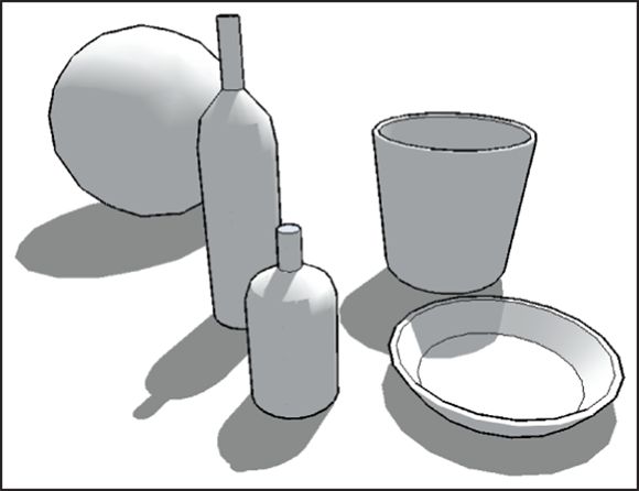
FIGURE 6-5: A few examples of lathed objects created with Follow Me.
Creating extruded shapes like gutters and handrails
A lot of the time, you want to use Follow Me to create geometry (edges and faces) that’s attached to another part of your model. An example of this may be modeling a gutter that runs all the way around the roof of your house. In this case, you already have the path along which you want to extrude a profile (the edge of the roof).
When you use Follow Me to extrude a face along a path that consists of edges that already exist as part of your model, always do two things:
·  Before using Follow Me, make the rest of your model a separate group. Take our word for it — Follow Me can sometimes mess up your model, so keep the geometry Follow Me creates separate, just in case.
·  Make a copy of your extrusion path outside your group. There’s a consequence to working with Follow Me on top of a group: The edge (or edges) you want to use as an extrusion path aren’t available because you can’t use Follow Me with a path that’s in a separate group or component.
What to do? You need to make a copy of the path outside the group and then use the copy to do the Follow Me operation. Here’s the best way to make a copy of the path:
1. With the Select tool, double-click your group to edit it.
2. Select the path you want to use for Follow Me and then choose Edit ⇒ Copy.
3. Exit (stop editing) your group by clicking somewhere else in your modeling window.
4. Choose Edit ⇒ Paste in Place.
You have a copy of the path you want to use, and it’s outside your group.
The Weld Ruby script is a SketchUp extension that's super-useful for creating extrusion paths for Follow Me. Chapter 16 introduces the Extension Warehouse, where you find SketchUp extensions.
When you use an existing edge (or series of edges) as an extrusion path, the hard part is getting your profile in the right place. You can proceed in two ways; which one you choose depends on what you need to model:
· Draw the profile in place. Do this only if the extrusion path is parallel to one of the colored drawing axes.
· Draw the profile on the ground and then move it into position. If your extrusion path doesn’t start out parallel to a colored drawing axis, you should probably draw your profile somewhere else and move it into place later.
WHY YOUR COMPUTER IS SO SLOW
When you use Follow Me with an extrusion profile that’s a circle or an arc, you create a piece of 3D geometry that’s very big. In this case, big, means that the geometry has lots of faces, and faces are what slow down your computer. Without going into detail about how SketchUp works (we don’t really know that anyway), keep this in mind: The more faces you have in your model, the worse your computer’s performance will be. At a certain point, you’ll stop being able to orbit, your scenes (introduced in Chapter 11 ) will stutter, and you’ll be tempted to do something terrible out of frustration.
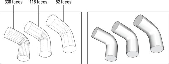
The first pipe in the figure that follows has been extruded using Follow Me; it was made with a 24-sided circle as an extrusion profile, and it has 338 faces. Hidden Geometry is turned on (in the View menu) so that you can see how many faces you have.
The second pipe uses a 10-sided circle as an extrusion profile. As a result, it has only 116 faces. What an improvement!
The third pipe also uses a 10-sided circle as an extrusion profile, but the arc in its extrusion path is made up of only 4 segments, instead of the usual 12. This pipe has a total of 52 faces. Even better.
The second image in the figure shows all three pipes with Hidden Geometry turned off. Is the difference in detail worth the exponential increase in the number of faces? Most of the time, the answer is no.
To change the number of sides in a circle or an arc, just before or just after you create it, follow these steps:
1. Type the number of sides you want to have.
2. Type an s to tell SketchUp that you mean “sides.”
3. Press Enter.
Drawing your profile in place
Consider that you have a model of a house. You want to use Follow Me to add a gutter that goes all the way around the perimeter of the roof. You decide to draw the profile in place (right on the roof itself) because the edges of the roof are drawn parallel to the colored drawing axes. This means that you’ll have an easier time using the Line tool to draw in midair.
The trick to drawing an extrusion profile that isn’t on the ground is to start by drawing a rectangular face. You then draw the profile on the face and erase the rest of the rectangle. Figure 6-6 shows how you’d draw the profile of a gutter directly on the corner of a roof; the steps that follow explain the same things in words:
1. Zoom in on what you’re doing.
Many people try to work without filling their modeling windows with the subject at hand. Not doing so is like trying to do a crossword puzzle while looking the wrong way through a pair of binoculars. Get close — SketchUp models don’t bite!
2. Using the Line tool, draw a rectangle whose face is perpendicular to the edge you want to use for Follow Me.
Pay careful attention to SketchUp’s inference engine, introduced in Chapter 3 . Watch the colors to make sure that you’re drawing in the right direction.
3. Use the Line tool (and SketchUp’s other drawing tools) to draw your profile directly on the rectangle you just drew.
The important thing here is to make sure that your extrusion profile is a single face; if it’s not, Follow Me won’t work the way you want it to.
4. Erase the rest of your rectangle, leaving only the profile.
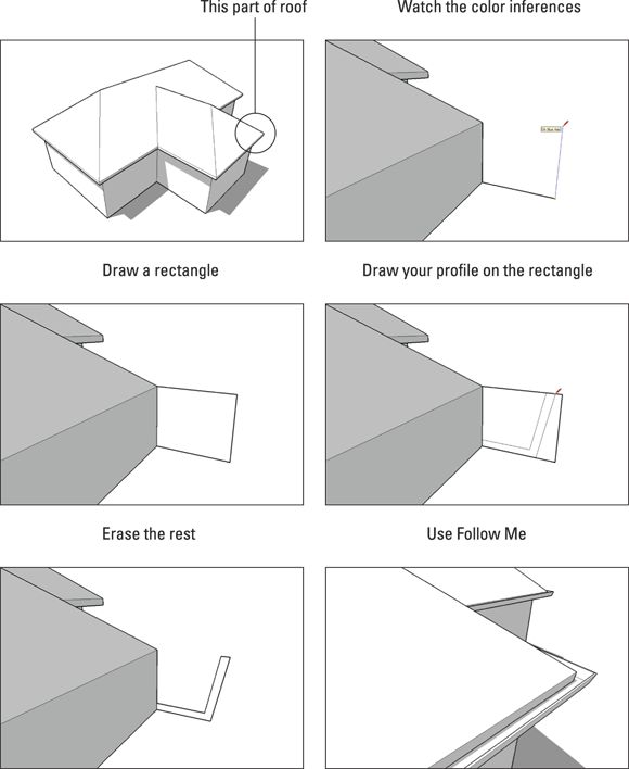
FIGURE 6-6: Drawing an extrusion profile in place by starting with a rectangle.
Drawing your profile somewhere else
The awful thing about handrails is that they’re almost always at funny angles, not parallel to a colored axis. When drawing your extrusion profile in place isn’t convenient, draw it on the ground and move it into position after.
Here’s the trick: Draw a tail — a short edge — perpendicular to your extrusion profile. This tail helps you line up your profile with the edge that you want to use as an extrusion path for Follow Me. The following steps and Figure 6-7 describe how you’d draw and position a profile for a handrail:
1. Draw your extrusion profile flat on the ground.
2. Draw a short edge perpendicular to the face you just drew.
This tail should come from the point where you want your profile to attach to the extrusion path.
3. Make your profile and its tail into a group.
This makes it easier to move and rotate around all at once. See Chapter 5 for information on creating and using groups.
4. Using the Move tool, place your profile at the end of the extrusion path.
To make sure that you position your profile accurately, pick it up by clicking the point where the tail meets the face and then drop it by clicking the end of the extrusion path.
5. With the Rotate tool, rotate your profile into position.
Here’s where you need to use a bit of skill. (See Chapter 3 for guidance.) The Rotate tool is easy to use — after you get the hang of it.
6. Context-click the group you made in Step 3 and choose Explode; delete your tail.
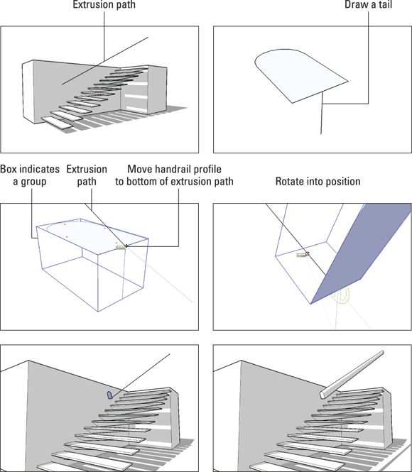
FIGURE 6-7: Draw a short tail on your extrusion profile to help you position it with the Move and Rotate tools.
Subtracting from a model with Follow Me
What if you want to model a bar of soap? Or a sofa cushion? Or anything that doesn’t have a sharp edge? The best way to round off edges in SketchUp is to use Follow Me. In addition to using Follow Me to add to your model, you can also subtract from your model.
Here’s how it works: If you draw an extrusion profile on the end face of a longish form, you can use Follow Me to remove a strip of material along whatever path you specify. Figure 6-8 demonstrates the concept on the top of a box.
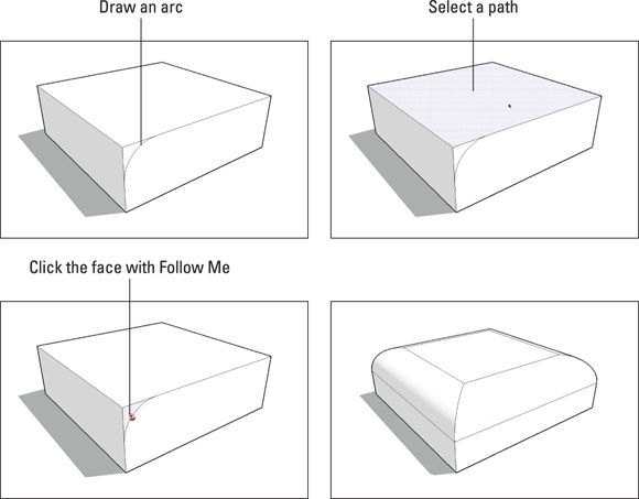
FIGURE 6-8: Creating a rounded edge with Follow Me.
If the extrusion path you want to use for a Follow Me operation consists of the entire perimeter of a face (as is the case in Figure 6-8 ), you can save time by just selecting the face instead of all the edges that define it.
But what if you want to create a corner that’s rounded in both directions, as so many corners are? That one’s a little trickier to do. The basic technique involves using Follow Me on a corner you’ve already rounded with the Push/Pull tool. After you round a corner with an arc of the correct radius, you can use copies (or component instances, if you’re clever) of that corner several times, wherever you need them. Although we wouldn’t call this solution elegant, it works.
Figure 6-9 gives a step-by-step, visual account of the process, while the following steps explain it in words, as follows:
1. Draw a box.
The box should be big enough for the round you want to apply.
2. With the 2 Point Arc tool, draw an arc on the corner of the box.
When you’re drawing an arc on a corner, keep an eye out for the inferences that help you draw properly:
o After clicking to place one endpoint of your arc, as you cut across the corner, the point at which your line turns magenta is where your endpoints are equidistant (the same distance) from the corner across which you’re cutting.
o After clicking to place your second endpoint, you see a point at which the arc you’re drawing turns magenta — this means your arc is tangent to (continuous with) both edges it’s connected to. You want this to be the case, so you should click when you see magenta.
Reduce the number of sides on your arc before you start rounding away. See the sidebar “Why your computer is so slow ,” earlier in this chapter, to find out why.
3. Push/pull down the new face to round off the corner.
4. Draw another identical arc on one of the corners directly adjacent to the corner you just rounded.
This is where you refer to Figure 6-9 . Pictures are better than words when explaining things like adjacent corners.
5. Select the edges shown in Figure 6-9 .
6. Choose Tools ⇒ Follow Me.
7. Click the arc corner face to extrude it along the path you selected in Step 5.
8. Hide or smooth any edges that need it.
For information about hiding edges, see Chapter 5 . Check out this chapter’s “Smoothing those unsightly edges ” sidebar for the whole scoop on how to smooth edges.
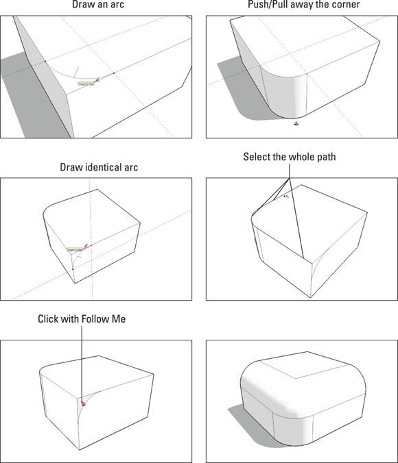
FIGURE 6-9: Making a corner that’s rounded in both directions.
After you have a fully rounded corner, you can use a bunch of them to make anything you want; it just takes a little planning. Figure 6-10 shows a simple bar of soap created out of eight rounded corners, copied, and flipped accordingly. The text (in case you’re wondering) was created with SketchUp’s 3D Text tool, which you can find on the Tools menu.
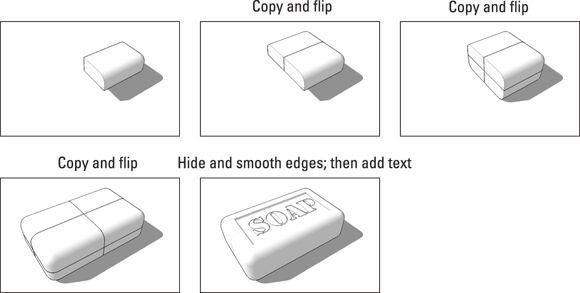
FIGURE 6-10: Assembling a bunch of rounded corners to make objects is relatively easy.
SMOOTHING THOSE UNSIGHTLY EDGES
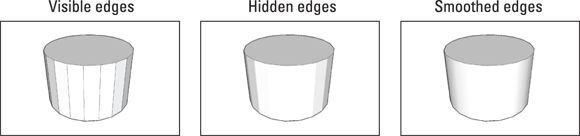
If you’re wondering how to get rid of all the ugly lines that appear when you use Follow Me, the answer is pretty simple: You can smooth edges, just like you can hide them. (See Chapter 5 for more information about hiding edges.) The difference between hiding and smoothing is illustrated by the images of the cylinders in the figure that follows:
· When you hide an edge between two faces, SketchUp treats those faces as though your edge is still there — it just doesn’t show the edge. Materials you’ve applied to each face stay separate, and each face is lit separately by SketchUp’s sun. The latter fact is the reason why simply hiding the edges between faces that are supposed to represent a smooth curve doesn’t make things look smooth — you still end up with a faceted look, as you can see in the second cylinder.
· When you smooth an edge between two faces, you’re telling SketchUp to treat them as a single face — with a single material and smooth-looking shading. The difference is pretty huge, as you can see in the third cylinder in the figure.
You can smooth edges in two ways:
· Use the Eraser. To smooth edges with the Eraser tool, hold down the Ctrl key (Option on the Mac) while you click or drag over the edges you want to smooth.
· Use the Soften Edges panel. Located on the Window menu, this panel lets you smooth a bunch of selected edges all at once, according to the angle of their adjacent faces. To get started: Select the edges you want to smooth and then move the slider to the right until you like the way your model looks.
To unsmooth edges, follow these steps:
1. Choose View ⇒ Hidden Geometry so that the Hidden Geometry menu option is selected.
This makes hidden edges visible.
2. Select the edges you want to unsmooth.
3. In the Soften Edges panel, move the slider all the way to the left.
Modeling with the Scale Tool
Real heroes are rarely obvious. The Scale tool is the single most misunderstood member of SketchUp’s mercifully limited toolkit. New modelers assume that Scale is for resizing things in your model. That’s technically true, but most folks only use it to resize whole objects; the real power of Scale happens when you use it on parts of objects to change their shape. Figure 6-11 illustrates how Scale can distort basic shapes into more complex ones.
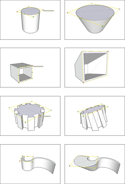
FIGURE 6-11: Using the Scale tool on parts of objects changes their shape.
Getting the hang of Scale
The basic principle of this technique is pretty simple: You select the geometry (edges and faces) in your model that you want to resize, activate the Scale tool, and go to town.
Here’s a list of steps, just so it’s crystal clear. Figure 6-12 tells the story in pictures:
1. Select the part of your model that you want to scale.
Use the Select tool to do this; check out Chapter 3 for details about making selections.
2. ![]() Activate the Scale tool by choosing Tools ⇒ Scale.
Activate the Scale tool by choosing Tools ⇒ Scale.
You can also make Scale active by clicking its button on the toolbar or by pressing the S key on your keyboard. After you activate Scale, the geometry you selected in Step 1 should be enclosed in a box of little green cubes, or grips.
3. Click a grip and then move your mouse to start scaling your selected geometry.
Keep reading for the lowdown on the different grips.
4. When you’re finished scaling, click again to stop.
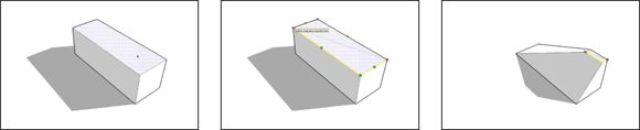
FIGURE 6-12: The Scale tool is a cinch to use.
While we're on the subject of Scale, here are a few more things you should know:
· Use different grips to scale different ways. Which grip (the little green boxes that appear when you activate the Scale tool) you use determines how your geometry scales:
o Corner grips scale proportionally — nothing gets distorted when you use them.
o Edge and side grips distort your geometry as you scale — use them to squeeze what you’re scaling.
· Hold down the Shift key to scale proportionally. This happens automatically if you’re using one of the corner grips, but not if you’re using any others. If you don’t want to distort what you’re scaling, hold down Shift.
· Hold down the Ctrl key (Option on a Mac) to scale about the center of your selection. You might find yourself doing this more often than not.
· Type a scaling factor to scale accurately. To scale by 50 percent, type 0.5 . Typing 3.57 scales your geometry by 357 percent, and typing 1.0 doesn’t scale it at all. Take a look at Chapter 3 to read more about using the Measurements box while you work.
· Type a specific measurement. If you know the final dimension you’re trying to achieve with the Scale tool, you can type it in, followed by the units. To scale a 4-foot box until it’s 10 feet wide, type 10’ .
· Which grips appear depend on what you’re scaling. Have a look at the differences in Figure 6-13 .
o Most of the time, you see a scaling box enclosed by 26 green grips.
o If you’re scaling flat, coplanar geometry (faces and edges that all lie on the same plane) and that plane is perfectly aligned with one of the major planes in your model, you see a rectangle consisting of 8 grips instead of a box with 26.
o If what you’re scaling is a Dynamic Component, you may see anywhere from 0 to all 26 grips, depending on how the builder set up the component. Chapter 5 introduces Dynamic Components.
· You can’t make a copy while you scale. Both the Move and Rotate tools let you make copies by holding down a button on your keyboard while you’re using them, but Scale doesn’t work this way. If you need to make a scaled copy, try this instead:
o Select the geometry that you want to scale and copy, and then make it into a group.
See Chapter 5 for more information on making groups.
o Choose Edit ⇒ Copy from the menu bar and then choose Edit ⇒ Paste in Place from the menu bar.
o Scale the copied group as you would anything else.
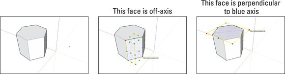
FIGURE 6-13: Grips depend on what you’re trying to scale.
Scaling profiles to make organic forms
Here’s where it gets really interesting. We need to thank über-SketchUpper Justin Chin (who goes by the handle monsterzero online) for demonstrating the power of scaling profiles to make organic forms. The method is great because it’s easy to understand and powerful enough to be applied all over the place.
So what is this method? You use the Scale tool in combination with a series of 2D profiles to create curvy, lumpy, distinctly un-boxy 3D shapes. An awful lot of the stuff in the universe fits squarely in this category: us, you, slugs, intergalactic alien fighter vessels, bananas — just about everything that wasn’t made by a machine can be modeled using the scaled profiles method of 3D modeling.
On the Extension Warehouse, you find the FredoScale SketchUp extension, which is hyper-relevant to the material in this section. After you're comfortable with the techniques we describe in this section, check out the extension. We introduce the Extension Warehouse in Chapter 16 .
Combining Scale and Push/Pull
The simplest way to use this method is in association with Push/Pull. Here’s a very simple example of how it works. Check out Figure 6-14 for an illustrated view:
1. Create a 2D shape.
This shape may be something simple (such as a circle) or something more complex; it all depends on what you’re trying to model. The shape may also be a half-shape if what you’re trying to make exhibits bilateral symmetry. Take a look at the last section in Chapter 5 for more information on using components to build symmetrical models.
2. Push/pull your 2D shape into a 3D form.
3. Scale the new face you created so it’s slightly bigger (or slightly smaller) than the original 2D shape from Step 1.
See the previous section in this chapter for more specifics about using the Scale tool. Pay special attention to the points about using modifier keys, or keyboard buttons, to scale proportionally or about the center of what you’re working on.
4. Push/pull the face you scaled in the preceding step.
Try to make this extrusion about the same as the one you made in Step 2.
You can usually double-click a face with the Push/Pull tool to repeat the last Push/Pull operation you did.
5. Repeat Steps 3 and 4 until you’re done.
You can add skillful use of the Rotate tool into the mix if you like; doing so allows you to curve and bend your form as you shape it.
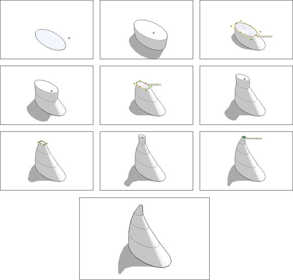
FIGURE 6-14: Using Scale and Push/Pull together is a simple way to make organic forms.
Keep the following tidbits in mind as you explore this technique:
· Watch your polygon count. Polygons are faces, basically — the more you have, the “heavier” your model becomes, and the worse it performs on your computer. Try to minimize the number of faces you’re working with by reducing the number of edges in your original 2D shape. Have a look at the sidebar “Why your computer is so slow ,” earlier in this chapter, for the whole scoop.
· Don’t be afraid to go back and tweak. The beauty of this method is its flexibility. While you’re working, you can select any of the 2D profiles (shapes) in your model and use the Scale tool to tweak them. Just select the loop of edges along the perimeter of the profile you want to scale and take it from there. Figure 6-15 illustrates an example of how you can tweak a shape by scaling.
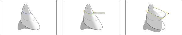
FIGURE 6-15: You can go back and scale any profile at any time while you work.
Combining Scale and Follow Me
Another way to create extruded forms is to use Follow Me. (See the first part of this chapter if you need a refresher.) This technique is ideally suited to making long, curvy, tapered things like tentacles and antlers; it’s a little time-consuming but works like a charm.
Modeling a simplified bull’s horn is a good, straightforward illustration of how the Follow Me variation of this method works. Here’s how to go about it; take a look at Figure 6-16 to see the story in pictures:
1. Draw a circle.
This is the extrusion profile for Follow Me. Strongly consider reducing the number of sides in your circle from the standard 24 to something more like 10 or 12. See the sidebar “Why your computer is so slow ” (earlier in this chapter) to find out how and why you should do this.
2. Draw a 10-sided arc that starts perpendicular to the center of the circle you drew in Step 1.
Type 10s and press Enter right after you click to finish drawing your arc.
This tells SketchUp to make sure your arc has 10 sides (instead of the default 12). Why 10 sides? It makes the math easier a few steps from now.
The easiest way to create a halfway-accurate arc in 3D space is to start by drawing a rectangle. When you’re sure this rectangle is properly situated, use one of the arc tools to draw on top of the rectangle and then delete everything but the arc.
3. Select the arc you just drew.
This is the extrusion path for Follow Me.
4. Activate the Follow Me tool by choosing Tools ⇒ Follow Me from the menu bar.
5. Click the circle you drew in Step 1 to extrude it along the path you drew in Step 2.
6. Choose View ⇒ Hidden Geometry from the menu bar.
Showing the hidden geometry in your model lets you select the edges that were automatically smoothed (made hidden) when you used Follow Me in Step 4.
7. Scale the face at the end of your new extrusion by a factor of 0.1.
See “Getting the hang of Scale ,” earlier in this chapter, for instructions on how to do this. Use any of the four corner grips on the scaling box, and don’t forget to hold down the Ctrl key (Option on a Mac) while you’re scaling — this forces SketchUp to scale about the center of the face you’re resizing.
8. Select the edges that define the next-to-last profile in your extruded form.
Depending on the angle of your arc, making this selection can get tricky. Here are some tips that may help:
o See Chapter 3 for tips on making selections.
o Choose View ⇒ Face Style ⇒ X-Ray or View ⇒ Edge Style ⇒ Back Edges from the menu bar to make it easier to see what you’ve selected.
o Hold down the Ctrl key (Option on a Mac) while you orbit to turn off SketchUp’s “blue is up/down gravity bias.” While orbiting this way, try drawing lots of tight, little circles with your mouse to get your view to tilt in the direction your want. This is by no means simple stuff, but getting the hang of temporarily disabling the Orbit tool’s tendency to keep the blue axis straight up and down is a very nifty way to work. Doing so makes it infinitely easier to get just the right angle for making a window selection. This in turn makes selecting the edges that define profiles a whole lot easier, and that’s what becoming a Zen master of the Orbit tool is all about.
9. Scale the edges you selected in the preceding step by a factor of 0.2.
Starting to see what’s happening?
10.Repeat Steps 8 and 9 for each of the remaining profiles in your form, increasing the scaling factor by 0.1 each time.
Of course, you can absolutely choose to sculpt your form however you like, but this method (counting up by tenths) yields a smooth taper.
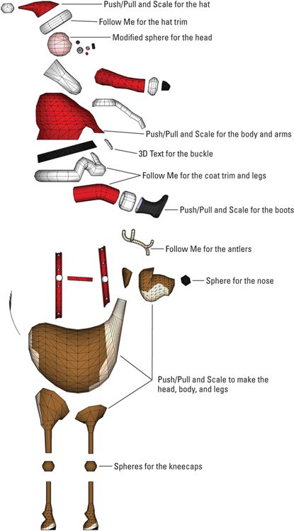
The Santa-Claus-and-reindeer project illustrates the kind of fancy, not-a-box models you can build after you master the Scale tool. It’s not beginner-level material, but it’s worth the time when you’re ready.
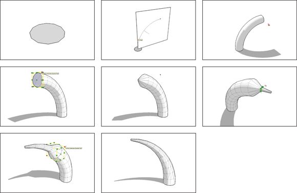
FIGURE 6-16: Use Scale with Follow Me to create long, tapered forms like this bull’s horn.
Making and Modifying Terrain
Continuing in the grand tradition of building extremely powerful tools and then hiding them so you’ll never find them, the people at SketchUp introduced the Sandbox way back in version 5 of the software. We introduce the Sandbox here because it helps people to model terrain — the stuff your buildings sit on (or in, if what you’re making is underground).
The Sandbox isn’t new, but owing to its less-than-obvious location, most SketchUp users have never used it. Here are the facts:
· The Sandbox is a collection of tools. Each tool serves a fairly specific purpose and is meant to be used at a particular stage of the terrain-modeling process. That said, like all SketchUp’s tools, they’re incredibly flexible. You can use them to model anything you want.
· The Sandbox is in both Make and Pro. Despite what many people think, the Sandbox tools aren’t just for Pro users; people who use the free version of SketchUp can use them, too. They’re just hidden, which brings you to our next point.
· The Sandbox is hidden. The reasons for this are complicated, but the tools in the Sandbox are a little bit special; they’re extensions — you have to find them and turn them on before you can use them. If you’re using SketchUp Pro, you can skip the first two steps in the following list — they’re already turned on.
Follow these steps to switch on the Sandbox tools:
1. Choose Window ⇒ Preferences from the menu bar to open the Preferences dialog box.
Choose SketchUp ⇒ Preferences if you’re on a Mac.
2. In the Extensions panel, make sure the Sandbox Tools check box is selected and then close the Preferences dialog box.
3. Choose View ⇒ Toolbars ⇒ Sandbox from the menu bar to show the Sandbox toolbar.
Creating a new terrain model
Whether you’re modeling a patch of ground for a building or redesigning Central Park, you need one of two terrain-modeling methods:
· Starting from existing data: This existing data usually arrives in the form of contour or topo lines; see the next section to read more about them.
· Starting from scratch: If you don’t have any data to start or if you’re beginning with a perfectly flat site, you can use SketchUp’s From Scratch tool to draw a grid that’s easy to form into rolling hills, berms, and valleys. Skip ahead to “Modeling terrain from scratch ” for more information.
There’s a neat trick Aidan learned for modeling small (yard-sized) amounts of terrain — the piece of land immediately surrounding a building, for example. You could use the From Scratch tool to start with a flat site, but there’s a better way: See “Roughing out a site ” a little later in this chapter.
Modeling terrain from contour lines
You know the squiggly lines on topographical maps that show you where the hills and valleys are? They’re contour lines (or contours ) because they represent the contours of the terrain; every point on a single line is the same height above sea level as every other point on that line. Where the lines are close together, the ground between them is steep. Where the lines are far apart, the slope is less steep. Cartographers, surveyors, engineers, and architects use contour lines to represent 3D terrain in flat formats like maps and site drawings.
Sometimes, you have contour lines for a building site that you want to model in 3D. You can use the From Contours tool in the Sandbox to automatically generate a three-dimensional surface from a set of contour lines, as shown in Figure 6-17 .
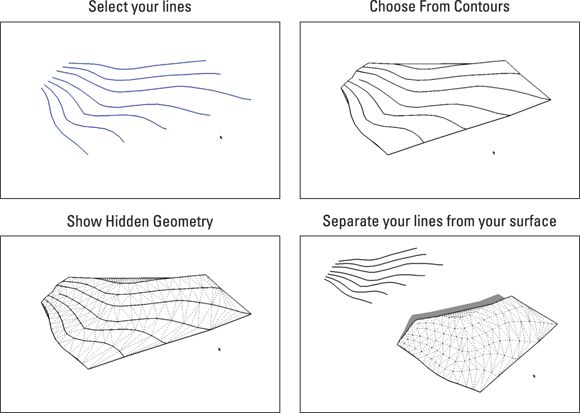
FIGURE 6-17: Use the From Contours tool to turn a set of contour lines into a 3D surface.
Here are some things to keep in mind about the From Contours tool:
· It’s a two-step tool. Using From Contours is simple after you get the hang of it:
1. Select all the contour lines you want to use to create a surface.
2. Choose Draw ⇒ Sandbox ⇒ From Contours from the menu bar (or click the From Contours tool button, if the Sandbox toolbar is visible).
Note: If you can’t see the Sandbox tools in your menus, you haven’t turned them on yet. See the beginning of this section, “Making and Modifying Terrain ,” to rectify the situation.
· Your contour lines need to be lifted up. The From Contours tool creates a surface from contour lines that are already positioned at their proper heights in 3D space. Most of the time you work with contours that are part of a 2D drawing, and that means you probably have to lift them up yourself using the Move tool — one at a time. It’s tedious but necessary. Just oil up the Select tool, put on some music, and get to work. For a refresher on selecting things, take a look at the last part of Chapter 3 .
· Download and install Weld. The Weld SketchUp extension turns selections of individual line segments into polylines — this makes them much, much easier to work with. If you work with contour lines imported from a computer-aided drawing (CAD) file, using Weld makes your life a little easier. To add Weld to SketchUp, visit the Extension Warehouse, introduced in Chapter 16 .
· You end up with a group. When you use From Contours, SketchUp automatically makes your new surface (the one you generated from your contour lines) into a group. It leaves the original lines themselves completely alone; you can move them away, hide them, or delete them if you want. We recommend making another group out of them, putting them on a separate layer (see Chapter 7 for more on this), and hiding that layer until you need it again.
To edit the faces and edges inside a group, double-click it with the Select tool. Chapter 5 has all the details on groups and components.
· To edit your new surface, turn on Hidden Geometry. The flowing, organic surface you just created is actually just a bunch of little triangles. The From Contours tool smooths the edges that define them, but they’re there. To see them, choose View ⇒ Hidden Geometry from the menu bar.
· Try to keep your geometry reasonable. The From Contours tool is super useful, but it has its limits. The trouble is that it’s too easy to use it to create enormous amounts of geometry (faces and edges) that can really bog down your system. If it takes forever for your contours to turn into a surface, or if that surface is so big that your computer turns blue and curls up into a fetal position (so to speak), you need to go back a few steps and do one (or perhaps all) of the following:
o Work on a smaller area. As nice as it’d be to have the whole neighborhood in your SketchUp model, you may have to narrow your scope. Creating only what you need is good modeling policy.
o Use only every other contour line. Doing this effectively halves the amount of geometry in your resulting surface.
o Dumb down the contour lines. This is a little bit hard to explain, but here goes: The From Contours tool works by connecting adjacent contour lines together with edges that form triangles. How many triangles it creates depends on how many individual edge segments are in each contour line; Figure 6-18 provides an illustration. Unless you created the contour lines to begin with — there’s a good chance you imported them as part of a CAD file — you have no control over how detailed they are. Redrawing each contour line is a major bummer, but luckily, you can download a great Simplify Contours extension that makes the process much simpler.
· You don’t have to start with existing contour lines. In fact, drawing your own edges and using From Contours to generate a surface from them is one of the most powerful ways to create organic, nonboxy forms in SketchUp. The next section, "Modeling terrain from scratch ," has more details.
· Get ready to do some cleanup. The surfaces that From Contours creates usually need to be cleaned up to some extent. Use the Eraser to delete extra geometry (you’ll find lots along the top and bottom edges of your surface). Use the Flip Edge tool to correct the orientation of your triangular faces. See the nearby sidebar “Don’t flip out — Flip Edge ” for the lowdown.
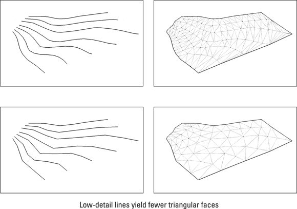
FIGURE 6-18: How many triangles are created depends on the number of edge segments in the contour lines you start with.
DON’T FLIP OUT — FLIP EDGE
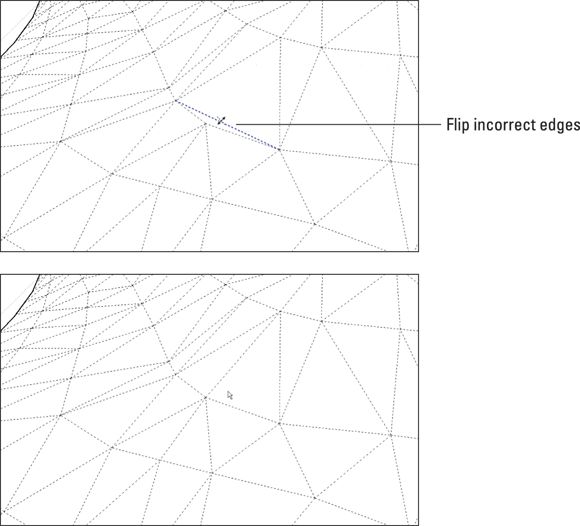
The Sandbox’s Flip Edge tool is a simple beast, but it’s indispensable if you’re working with the From Contours tool. Basically, you use Flip Edge to clean up the surfaces that From Contours creates. When you turn contour lines into a surface, lots and lots of triangular faces appear. Sometimes, the From Contours tool decides to draw an edge between the wrong two line segments, creating two triangular faces that form a “flat spot” in your surface. See the following image.
You get rid of these flat spots manually by flipping the edges that create them. Doing so changes the resulting triangular faces, usually making them end up side by side (instead of one above the other).
To use the Flip Edge tool (choose Tools ⇒ Sandbox ⇒ Flip Edge), just click the edge you want to flip. If you’re not sure about an edge, go ahead and flip it; then see if things look better. If they don’t, you can always undo or flip it back.
Modeling terrain from scratch
Without contour lines that define the shape of the terrain you want to model, you have to start with a level surface. Use the From Scratch tool to create a big, flat rectangle that represents a chunk of ground. Because the rectangle is already divided into triangular faces, it’s easy to use the Smoove tool (discussed next in this chapter) to shape the rectangle into hills, valleys, sand traps, and whatever else you have in mind.
Here’s the thing, though: It’s a very rare occasion that you have carte blanche with a piece of land. Unless you design something like a golf course in the middle of a dry lake bed or terraform a new planet for colonization, you probably have preexisting terrain conditions to contend with. And if that’s the case, you’re probably better starting off with a set of contour lines that describe those conditions, as discussed earlier in this chapter.
So although the From Scratch Tool works great, you probably won't need to use it much. All the same, here’s how to do so, just in case.
Follow these steps to create a new terrain surface with the From Scratch tool and take a look at Figure 6-19 while you’re at it:
1. Choose Draw ⇒ Sandbox ⇒ From Scratch from the menu bar to activate the From Scratch tool.
2. Type a grid spacing amount and press Enter.
The default grid spacing amount is 10 feet, which means the tool draws a rectangle made up of squares that are 10 feet across. The grid spacing you choose depends on how big an area you’re planning to model and how detailed you plan to make the terrain for that model.
If Aidan were modeling a single-family house on a reasonably sized lot, he would probably use a grid spacing of 2 feet — that’d provide enough detail for elements like walkways and small berms without creating too much geometry for a computer to handle. If he were laying out an 18-hole golf course, on the other hand, he'd choose a grid spacing closer to 50 feet and then add detail to certain areas later.
3. Click to position one corner of your new terrain surface where you want it.
4. Click to determine the width of the surface you’re drawing.
5. Click to establish the length of your new terrain surface.
When you’re done, the great big rectangle you’ve created will automatically be a group. Double-click with the Select tool to edit it and get started. You’ll probably decide to use the Smoove tool next; jump ahead to “Making freeform hills and valleys with Smoove ” (later in this chapter) to find out how.
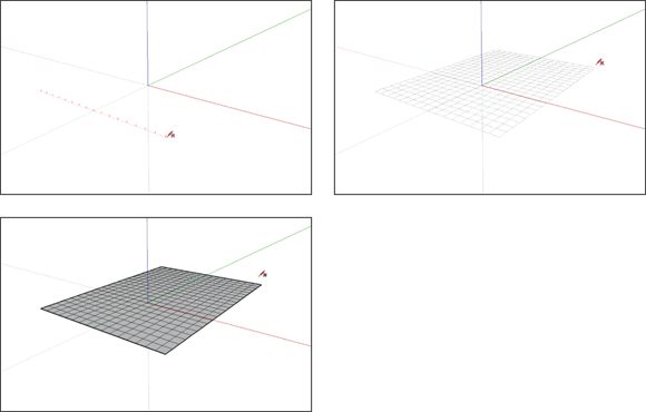
FIGURE 6-19: Use the From Scratch tool to create big swatches of flat terrain. Ah, the possibilities!
Roughing out a site
Perhaps you want to model a smallish chunk of nonflat terrain that surrounds a building. Maybe you’re trying to reproduce existing site conditions, or maybe you’re in the process of designing the landscape for a project. There’s a neat technique for cases like this one: You can use From Contours to quickly generate a surface from just a few simple outlines.
Follow these steps to model a simple terrain surface with the From Contours tool, as shown in Figure 6-20 :
1. Extend the bottom of your building down so the exterior walls drop below ground level.
2. Make your building into a group.
See Chapter 5 if you need help.
3. ![]() Use the Tape Measure and Line tools to draw the outline of the chunk of terrain you want to model around the building.
Use the Tape Measure and Line tools to draw the outline of the chunk of terrain you want to model around the building.
Keep in mind that the resulting horizontal face is flat; just pretend you’re drawing in 2D space. It doesn’t matter if the outline you draw is below, above, or in line with the building, as you see in the next step.
4. Use the Push/Pull tool to extrude the face you drew in Step 3 into a box that extends above and below your building, and then delete the top and bottom faces of the box you just drew.
5. Paint the walls of your box with a translucent material.
You can find some in the Translucent library, in the Materials panel. See Chapters 2 and 3 for help.
6. Draw edges on the sides of the box that represent where the ground should intersect them.
7. Draw edges on the sides of the building that represent where the ground meets the building.
8. Delete the box you created in Step 4, leaving the edges you drew in Step 6.
9. Select all the edges you drew in Steps 6 and 7.
10.Choose Draw ⇒ Sandbox ⇒ From Contours from the menu bar to generate a surface based on the edges you selected in the preceding step.
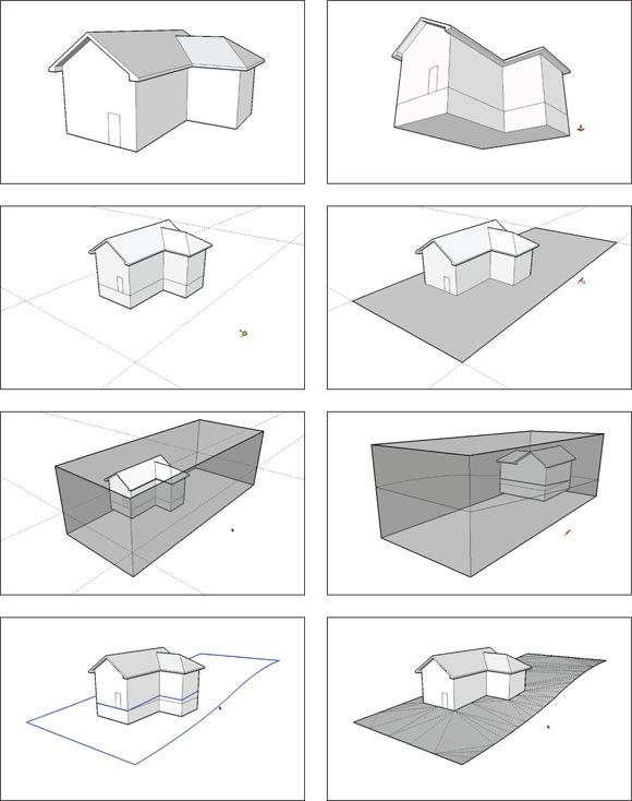
FIGURE 6-20: You can create irregular terrain surfaces very quickly with the From Contours tool.
Take a look at the section “Modeling terrain from scratch ” for tips on using From Contours; at this point, you need to use the Flip Edge tool and the Eraser to clean up your terrain model — particularly where your building is supposed to go.
Editing an existing terrain model
No matter how you make a terrain model, there’s a 99-percent chance that it consists of lots and lots of triangles. Switch on Hidden Geometry (choose View ⇒ Hidden Geometry) to see them. As long as you have triangles, you can use the Sandbox’s terrain editing tools. This section shows you how to do the following:
· Shape (or reshape) your terrain with the Smoove tool.
· Create a flat spot for a building with the Stamp tool.
· Draw paths and roads with the Drape tool.
Keep in mind that both From Contours and From Scratch create terrain objects that are groups. To edit a group, double-click it with the Select tool. When you’re done, click somewhere else in your modeling window.
Making freeform hills and valleys with Smoove
Smoove is a tool for moving smoothly — get it? Smooth + Move = Smoove. We’ll wait while you compose yourself.
Smoove is actually one of the coolest tools in SketchUp; it lets you shape terrain (or any horizontal surface that’s made up of smaller, triangular faces) by pushing and pulling (sort of) bumps and depressions of any size. Smoove is fun to use and yields results that you’d be hard-pressed to produce with any other tool in SketchUp. Figure 6-21 shows what Smoove can do.
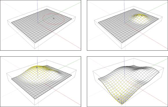
FIGURE 6-21: Smoove creates shapes that are unlike anything else you can make with SketchUp.
Follow these steps to shape a surface with Smoove:
1. Double-click the group containing your terrain to edit it.
If your terrain isn’t part of a group, forget this step.
2. ![]() Choose Tools ⇒ Sandbox ⇒ Smoove from the menu bar to activate the Smoove tool.
Choose Tools ⇒ Sandbox ⇒ Smoove from the menu bar to activate the Smoove tool.
3. Type a radius and press Enter.
Smoove creates lumps, bumps, and dimples that are circular. The radius you enter here determines how big those lumps, bumps, and dimples should be.
4. Click somewhere on your terrain surface to start smooving.
5. Move your mouse up or down (to create a bump or a depression, respectively), and then click again to stop smooving.
Fun, huh? Here are some more things to keep in mind when you use Smoove:
· Use the From Scratch tool beforehand. You don’t have to, but creating a surface with the From Scratch tool (described earlier in this chapter) is by far the easiest way to end up with terrain that you can smoove easily.
· Try smooving to edit other terrain surfaces. You can also use Smoove after you create a terrain surface with the From Contours tool.
· Double-click to repeat your previous smoove. As with Push/Pull, double-clicking tells SketchUp to carry out the same operation as you did the last time you used the tool.
· Preselect to smoove shapes other than circles. Any faces and edges you select before you use the Smoove tool will move up (or down) by a constant amount. This means you can use Smoove to create things like ridges and ditches by selecting the right geometry beforehand. Figure 6-22 provides a much-needed picture.
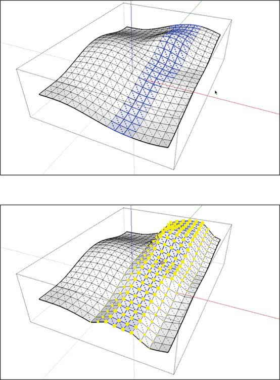
FIGURE 6-22: Preselect faces and edges to smoove shapes other than circles.
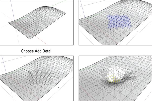
NEED MORE TRIANGLES? ADD DETAIL
Like the Flip Edge tool, Add Detail is kind of a one-trick pony. Use it to add triangles to areas of your terrain surface that need more detail. That way, you can save geometry (and file size, and waiting) by having lots of faces only in the areas of your terrain that require it. As Aidan mentions elsewhere in this chapter, if he were designing a golf course, he’d use very big triangles for the vast majority of it. He’d use the Add Detail tool to add triangles to areas where he planned to have smallish things like sand traps.
You can use the Add Detail tool in two ways:
· Add detail to faces one at a time. To be honest, you may never have a reason to use the tool this way, but here goes: You can activate the tool (see the next bullet) without having any geometry selected. Then click faces or edges on your terrain to divide them into more faces. This method might be handy when you model something very precisely.
· Add detail to an area all at once. Simply select the faces on your terrain you want to subdivide and choose Tools ⇒ Sandbox ⇒ Add Detail from the menu bar. Take a look at the figure to see what happens when you do.
Placing a building on your terrain with Stamp
Eventually, you may need to plunk down a building (or some other structure) on the terrain you’ve lovingly crafted. The Stamp tool provides an easy way to — you guessed it — stamp a building footprint into a terrain surface, creating a flat “pad” for something to sit on. This tool also provides a way to create a gently sloping offset around the perimeter of your stamped form. This creates a smoother transition between the new, flat pad and the existing terrain.
Follow these steps to use the Stamp tool; check out Figure 6-23 to see the corresponding pictures:
1. Move the building you want to stamp into position above your terrain surface.
The building shouldn’t touch the terrain but float in space directly above it. Also, turn the building into a group before you start moving anything; take a look at Chapter 5 to find out all about groups and components.
If you’re having trouble moving your building into position accurately, move it to the correct height first and then switch to a top, no-perspective view to finish the job. Look in the Camera menu for both these commands.
2. Choose Tools ⇒ Sandbox ⇒ Stamp from the menu bar to activate the Stamp tool.
3. Click the floating object to tell SketchUp what you want to use as the stamp.
4. Type an offset distance and press Enter.
The offset distance is the amount of space around the perimeter of whatever you’re stamping that SketchUp uses to smooth the transition between the flat spot it’s creating and the existing terrain. The offset amount you choose depends entirely on what you’re stamping. Go nuts, and thank your lucky stars for Undo.
5. Move your cursor over your terrain surface and click again.
6. Move (but don’t drag) your mouse up and down to position the flat pad in space. Click again to finish the operation.
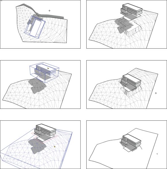
FIGURE 6-23: Use the Stamp tool to create a nice, flat spot for your building.
Here are a couple things that are handy to know when you use Stamp:
· SketchUp uses the bottommost face in your stamp object as the template for the flat pad it creates in your terrain.
· Read the “Don’t flip out — Flip Edge ” sidebar, earlier in this chapter; Stamp creates triangular faces that sometimes need cleaning.
Creating paths and roads with Drape
The Drape tool works a little like a cookie cutter; use it to transfer edges from an object down onto another surface, which is directly beneath it.
Perhaps you have a gently sloping terrain and you want to draw a meandering path on it. The path has to follow the contours of the terrain, but because you want to paint it with a different material, it needs to be a separate face. In this case, you’d draw the path on a separate face and use the Drape tool to transfer it to your terrain surface.
Taking the preceding example, follow these steps to use the Drape tool to draw a path on a nonflat terrain surface. Figure 6-24 illustrates the steps:
1. Use the Line tool (see Chapter 2 ) to draw a flat face somewhere directly above your terrain surface.
If you can, make your flat face exactly the same size as your terrain. Just make sure it’s big enough for whatever you plan to draw next (in this example, a path).
2. Paint the face you just created with a translucent material.
I find that a light gray works well; there’s a good one in the Translucent library, inside the Materials panel.
3. Use the Line tool to carry up any important points on your terrain surface.
In this case, make sure the path begins precisely at the door of the building, so draw vertical lines from the sides of the door to the flat face directly above. That way, you have something to inference to in Step 6.
4. Choose Camera ⇒ Standard Views ⇒ Top from the menu bar to switch to a top view.
5. Choose Camera ⇒ Parallel Projection from the menu bar to turn off perspective.
6. On the upper face, draw the edges you want to drape.
Make sure that your edges form closed loops to create faces. If they don’t, you’ll have a miserable time trying to paint the path (in this case) after it’s draped onto your terrain surface.
7. Orbit your model so you can see both the upper and lower surfaces.
8. Soften/smooth the edges of the triangles in your terrain surface (if they aren’t already).
To do this, follow these steps:
1. Select all the edges and faces in your terrain, and then choose Window ⇒ Soften Edges from the menu bar.
2. In the Soften/Smooth Edges panel, move the slider to the far right and make sure that both the Smooth Normals and Soften Coplanar check boxes are selected.
9. Select the edges you want to drape.
If your edges define closed faces, you can select those faces instead; sometimes that’s easier than selecting a bunch of individual edges. Take a look at Chapter 3 for tips on selecting things.
10.![]() Choose Draw ⇒ Sandbox ⇒ Drape from the menu bar to activate the Drape tool.
Choose Draw ⇒ Sandbox ⇒ Drape from the menu bar to activate the Drape tool.
11.Click once on your terrain surface to drape the edges you selected in Step 9.
It doesn’t matter if your terrain is inside a group — the Drape tool works anyway.
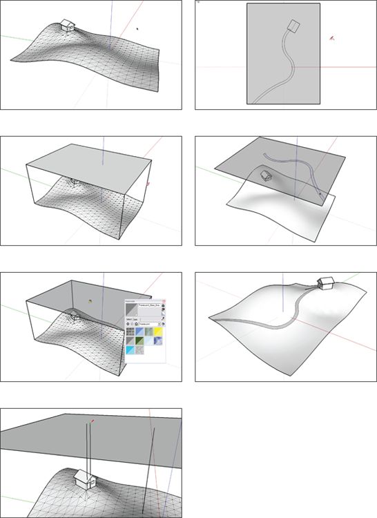
FIGURE 6-24: Use Drape to transfer edges onto your terrain surface.
Daniel Tal (a landscape architect and SketchUpper extraordinaire who regularly builds models that defy explanation) has written SketchUp for Site Design: A Guide to Modeling Site Plans, Terrain and Architecture(published by Wiley), which is available online and at your local bookstore. If you're a site designer, we highly recommend checking it out.
Building a Solid Tools Foundation
So-called solid modeling operations (fancy people refer to them as Boolean operations ) give you the ability to create the shapes you need by adding or subtracting other shapes to or from each other. In the next few pages, you discover how to use all six of SketchUp Pro’s Solid Tools, giving detailed examples for the three that are the most useful.
Five of the six Solid Tools are only in the Pro version of SketchUp. Take a look at Table 6-1 (later in this chapter) to see what’s available to you.
TABLE 6-1 The Solid Tools
|
Tool |
What It Does and How to Use It |
Start With |
End With |
|
Union |
What: Combines two or more solids into a single solid. Deletes overlapping geometry. Preserves internal pockets. * How: Select the solids you want to use and then activate the tool. |
Two+ solids |
One solid |
|
Outer Shell |
What: Combines two or more solids into a single solid. Deletes overlapping geometry, including internal pockets. * How: as Union tool. |
Two+ solids |
One solid |
|
Intersect |
What: Makes a single solid in which two or more solids overlap. Deletes everything else. How: Same as Union tool. |
Two+ solids |
One solid |
|
Subtract |
What: Uses one solid to cut away part of another solid. Deletes the first solid when it’s done. How: Activate the tool, click “cutting” solid, and then click solid to be cut. |
Two solids |
One solid |
|
Trim |
What: Uses one solid to cut away part of another solid. Keeps what’s left of both solids. How: Same as Subtract tool. |
Two solids |
Two solids |
|
Split |
What: Cuts two solids where they overlap and creates a new solid from the overlap. Doesn’t delete anything. How: Same as Union tool. |
Two solids |
Three solids |
* An internal pocket is like a solid within a solid — it’s a completely enclosed volume that happens to be located inside the main volume of a solid. Picture a SketchUp model of a tennis ball. Because tennis balls have a thickness, you’d need two surfaces to model one: one for the inside, and one for the outside. If you selected both and made a group, you’d have a solid with an internal pocket inside.
Understanding solids
Before you can use the Solid Tools, you need solids. Here are six things you need to know about solids; you can think of them as the Solid Rules:
· A solid is nothing more than an object that’s completely enclosed. It has no holes or other gaps; if you filled it with water, none would leak out. For this reason, solids are sometimes referred to as being watertight. Here’s another way to think about it: Every edge in a solid must be bordered by two faces.
· No extra edges or faces allowed. You wouldn’t think that one or two edges or faces would make much of a difference, but it does — solids can’t contain any extra geometry, period. Figure 6-25 shows some examples of things that can disqualify otherwise completely enclosed shapes from being solids.
A few SketchUp extensions make it easier to figure out why a particular group or component isn’t solid. For starters, check out Solid Inspector2 by ThomThom. For an introduction to the Extension Warehouse, see Chapter 16 .
· Only groups and components can be solids. This one’s a biggie. For SketchUp to realize something is a solid, you have to make it into either a group or a component first. Another thing: Solid groups and components can’t have other groups and/or components nested inside them.
· Making a solid doesn’t require any special tools. You don’t have to pick from a special list of objects to create solids; you make them with the same SketchUp tools you use all the time. Case in point: Every time you’ve pushed/pulled a rectangle into a box, you’ve created a solid.
· Check Entity Info to see if your object is a solid. The easiest way to tell whether a group or component is a solid is to select it and choose Window ⇒ Entity Info. If it’s solid, this panel will say either “Solid Group” or “Solid Component.” Figure 6-26 shows you where to look.
· Solids have volumes. Manually calculating the volume of a simple shape like a rectangular box is straightforward, but try it for anything more complicated and you’ll see why the Volume readout in Entity Info is so great. Figure 6-26 shows where to look.
· Solids can be made up of multiple shapes. This one is confusing at first. As long as each individual cluster of geometry within a group or component is completely enclosed, SketchUp considers that group or component to be a solid. It doesn’t matter that they’re not connected or touching in any way; what’s important is that an area of space is fully surrounded by faces.
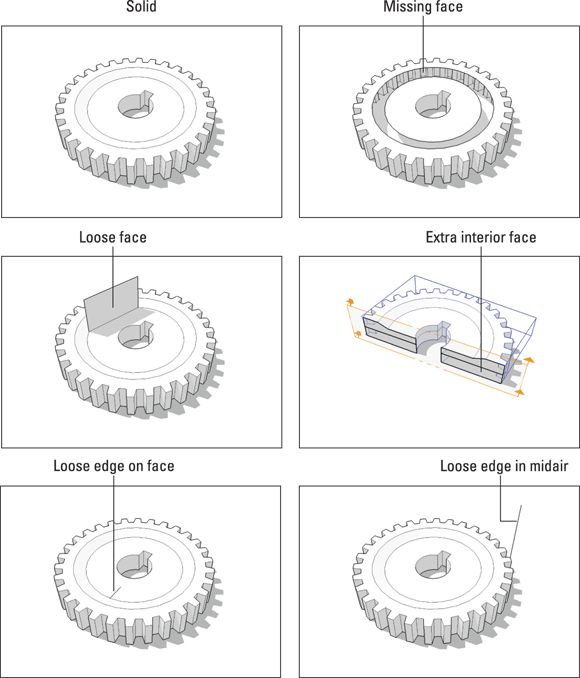
FIGURE 6-25: Solids can’t contain any extra edges or faces.
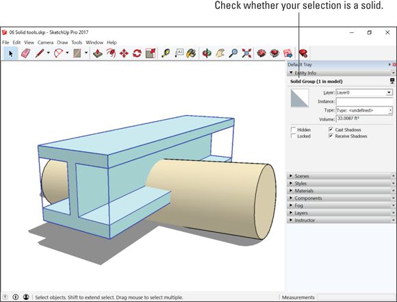
FIGURE 6-26: Check the Entity Info panel to see whether your selection is a solid.
Checking out the Solid Tools
When you have a solid object or objects, you can use SketchUp’s Solid Tools in powerful ways to create shapes that’d otherwise be very complicated and time-consuming to make. For example:
· Add two solids together to create a new one.
· Use one solid to cut away part of another one.
With the SketchUp Intersect Faces tool, you can achieve many of the same things that the Solid Tools do. Intersect Faces takes longer because it requires an awful lot of cleanup; however, it’s still useful for two very important reasons: It’s available in both the free and Pro versions of SketchUp, and it works on any face in your model — not just on solids. You can read about Intersect Faces in Chapter 4 .
Two things you need to know before you start using the Solid Tools:
· Open the dedicated toolbar. Choose View ⇒ Toolbars ⇒ Solid Tools to open the toolbar that contains all six tools. You can also find them on the Tools menu. Keep in mind that five of them — all but the Outer Shell tool — are available only if you have SketchUp Pro.
· To use the Solid Tools, preselect — or don’t. Pick the tool you want to use either before or after you’ve told SketchUp which solid objects you want to affect. Like most “order of operations” issues (are you listening, Follow Me tool?), this can be confusing for some folks.
The easiest way to use the Solid Tools is to preselect the solids and then choose the tool to carry out the operation. The glaring exceptions to this rule are the Subtract and Trim tools; both of these depend heavily on the order in which you pick your solids. Take a peek at Table 6-1 for more specifics.
Without further ado, here’s Table 6-1 with a rundown of the Solid Tools. (Check out Figure 6-27 for a visual.)
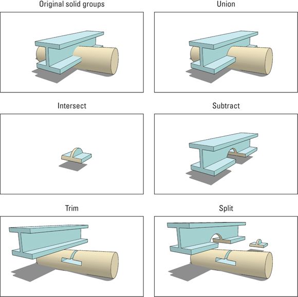
FIGURE 6-27: The Solid Tools let you do additive and subtractive modeling operations.
Note that the Split tool actually does three operations every time you use it: It yields two subtractions and an intersection. That is to say, using Split is like using both Subtract and Intersect on your solids. For this reason, you might want to use Split full-time. It’s easier to keep track of what’s going to happen, and the only downside is that you have to delete a couple extra objects when you're done.
Putting the Solid Tools to work
In this section, you find a few examples of everyday modeling challenges that the Solid Tools can help make less challenging. You’re almost certain to encounter these tricky situations while you climb the ladder toward ultimate SketchUp ninjahood.
Assembling complex objects with Union or Outer Shell
Chapter 4 has a section about using the Intersect Faces tool to combine multiple roof pitches into a single, solitary roof. If all those gables, hips, dormers, and other roof elements are solids, you can absolutely use SketchUp’s Union or Outer Shell tools to make quick work of the problem.
The same goes for anything that’s composed of several disparate elements that you’ve assembled by moving them together until they overlap. In the spacecraft in Figure 6-28 , the hull (or body) combines different pieces. Notice the lack of edges where the components intersect? We think edges add detail and definition, especially when a model is displayed using a lines-only style (as it is here). There’s also the issue of all the geometry hidden inside the hull. Combining everything together into a single solid helps it shed weight and look better, all at the same time.
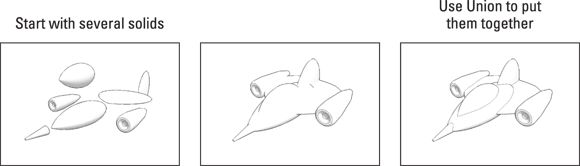
FIGURE 6-28: Using Union or Outer Shell to combine several solids gets rid of internal geometry and adds edges where faces intersect.
Using Intersect in combination with front, top, and side views
Anyone who’s ever tried to model a car with SketchUp knows it’s a tricky undertaking. The problem is that cars (and most other vehicles) are kind of curvy; worse yet, they’re curvy in several directions.
One trick lots of modelers use to block out a basic shape for things like cars is to start with orthographic — straight-on top, front, and side — views of the thing they’re trying to model. Here’s how the method works:
1. Position each 2D view where it belongs in 3D space.
2. Push/pull them all so their extrusions overlap.
3. Use the Intersect tool (Tools ⇒ Solid Tools ⇒ Intersect) to find the object that the extrusions all have in common.
This method doesn’t always produce perfect results, but it’s a lot better than guessing. Plus, it’s fun. Figure 6-29 shows the technique in action.
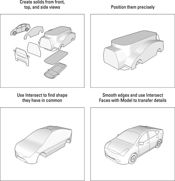
FIGURE 6-29: If you have orthographic views of the thing you’re trying to model, you can use Intersect to give yourself a head start.
Modeling close-fitting parts with Trim
Woodworkers and industrial designers, take heed: SketchUp Pro’s Trim tool saves you literally hours of work. Anytime you need to build a model with parts that interlock or otherwise fit together closely, Trim is where you should look first.
Trim basically tells one part to “take a bite” out of another, which is perfect for joinery (dovetails, finger joints, dadoes, and so on), machine parts, ball-and-socket joints, and any other positive/negative conditions where two parts meet.
Figure 6-30 shows how to build a small wooden box with dovetailed sides and a dadoed bottom.
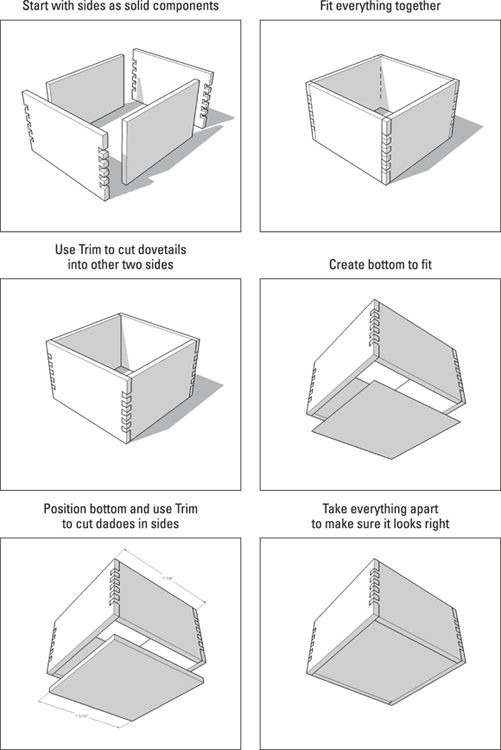
FIGURE 6-30: The Trim tool is perfect for modeling joinery and other close-fitting parts.
The only tricky thing about using the Trim tool is remembering which solid to pick first. Remember that the first thing you pick (or click) is the one you want to use to cut with. In the case of the box in Figure 6-30 , that would be the side with the dovetails. When you select the dovetails and then select the blank side, the Trim tool cuts the dovetails into the second piece. You get the hang of it after a few tries.
The Trim tool has a neat trick up its sleeve: You can keep using your cutting solid on multiple other solids. To cut the dado (or groove) into the sides of the box in Figure 6-30 , follow these steps:
1. Choose Tools ⇒ Solid Tools ⇒ Trim to activate the Trim tool.
Your cursor has the number 1 on it.
2. Select the box bottom.
Your cursor changes to show the number 2.
3. Select one side on the box.
You just cut a dado using the box bottom you picked in Step 2. Your cursor still says 2.
4. Select another of the box’s sides to create another dado.
5. Select the remaining two sides to cut dadoes in them, too.
Fun!
A question that comes up pretty frequently concerning what happens when you use one of the Solid Tools on a component instance. Why doesn’t the effect of what you just did affect all the other instances of that component? It should, shouldn’t it? Anyone who’s read Chapter 5 of this book should know that … .
Here’s the thing: As soon as you use a Solid Tool on a component instance, SketchUp makes that instance unique; it’s still a component — it just isn’t connected to the other instances anymore.
All materials on the site are licensed Creative Commons Attribution-Sharealike 3.0 Unported CC BY-SA 3.0 & GNU Free Documentation License (GFDL)
If you are the copyright holder of any material contained on our site and intend to remove it, please contact our site administrator for approval.
© 2016-2026 All site design rights belong to S.Y.A.