SketchUp For Dummies (2017)
Part 2
Modeling in SketchUp
Chapter 8
Modeling with Photos and Other Resources
IN THIS CHAPTER
![]() Applying photos to a model's faces
Applying photos to a model's faces
![]() Building a model from scratch with SketchUp’s photo-matching tools
Building a model from scratch with SketchUp’s photo-matching tools
![]() Using photo-matching to match your model to a photograph
Using photo-matching to match your model to a photograph
![]() Giving your model a geographic location
Giving your model a geographic location
![]() Starting out with a 2D CAD file in SketchUp Pro
Starting out with a 2D CAD file in SketchUp Pro
Building a model from scratch is all fine and well, but to help you along, SketchUp can import a whole lot of information — in the form of digital photos, 3D terrain data, and even existing 2D CAD.
If you have a model you want to paint with photographs, you can do that. You can apply photos to faces and then use the information in the pictures to help with modeling. Building windows is a lot easier when they’re painted right on the wall. That’s what we talk about in the first part of this chapter.
If you want to use a photo as a basis for modeling something that exists in the real world, you can do that in SketchUp, too. With the Match Photo feature, you can import a picture and trace what you see with SketchUp’s modeling tools.
If you're modeling a building or other structure that you plan to build on land, you can find your desired location on an online map and import the terrain right into your model — well, a digital representation of the terrain. (You can also import certain types of terrain files if you have those instead.)
If you’re working with SketchUp Pro, you can import a CAD file to use as a starting point for a 3D model. The import process isn't hard, but it's helpful to understand a few hints before you try it for the first time.
Painting Faces with Photos
Technically, painting surfaces with pictures using 3D software is called mapping, as in “I mapped a photo of your face to the underside of the pile-driver model I’m building.” Different software programs have different methods for mapping pictures to faces. Luckily, in SketchUp, the process is pretty straightforward.
The following sections deal with mapping photos to two kinds of faces: flat and curved. The tools are similar, but the methods aren’t. We explain both, because you never know what you’re going to run into.
 SketchUp uses lots of terms to refer to the stuff you can paint faces with; generically, they’re all materials. Materials can be colors or textures; textures are image-based, and colors are a single, solid hue. When you import an image to map it to a face, the images becomes a texture — just like any of the other textures in your Materials panel. Read more about using materials in Chapter 3 .
Adding photos to flat faces
When mapping photos onto flat faces, you can choose the hard way or the easy way. Unfortunately, the hard way is the method you end up using the vast majority of the time, so we describe it first. Importing images by using the File menu lets you take any image and map it to any flat face in your model.
The easy way is designed for one particular case: It gives you access to Google’s huge collection of Street View imagery, letting you paint your models with building facades photographed by Google’s roving fleet. The feature is cool, but also very specific.
Importing images: Use your own photos
Before you follow these steps, make sure you have at least one face in your model; you map your texture to a face. When you're ready, here's how to place the image onto that face:
1. Choose File ⇒ Import.
The Import dialog box opens.
2. Select the image file you want to use as a texture.
You can use JPEGs, TIFFs, and PNGs as textures in SketchUp; all these are common image file formats.
3. In the Use Image As area, select the Texture option, as shown in Figure 8-1 .
4. Click the Import button.
The Import dialog box closes, Paint Bucket becomes your active tool, and its cursor is loaded with the image you chose to import.
5. Click once in the lower-left corner of the face you want to paint. (See Figure 8-2 .)
Your click tells SketchUp where to position the lower-left corner of the image you’re using as a texture. Although you can click anywhere on the face you’re trying to paint, clicking the lower-left corner keeps things simple.
6. Click somewhere else on the face you’re painting. (See Figure 8-2 .)
Unless the proportions of your image perfectly match the face onto which it was mapped, your image repeats. Don’t worry — that’s normal. SketchUp automatically tiles your image to fill the whole face. If you want to edit your new texture so that it doesn’t look tiled (and you probably do), skip to the later section, “Editing your textures .” You can scale, rotate, skew, or even stretch your texture to make it look however you want. See the nearby sidebar, “When is an image a texture? ” for more background details.
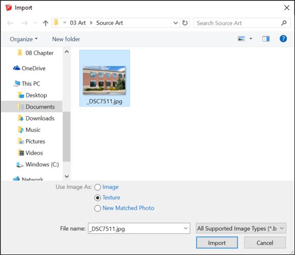
FIGURE 8-1: Tell SketchUp you want to use the image as a texture.
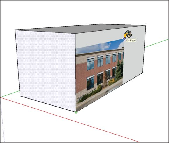
FIGURE 8-2: Click once to locate the lower-left corner of the image you’re using as a texture. Click again to locate the upper-right corner.
 WHEN IS AN IMAGE A TEXTURE?
Time for a little bit of theory: Image textures in SketchUp are made up of tiles. To make a large area of texture, such as a brick wall, SketchUp uses a bunch of tiles right next to each other. In the case of a brick wall, the face of a model may look like thousands of bricks, but the effect is really just the same tile of about 50 bricks repeated over and over again.
Because SketchUp treats imported image textures just like any other texture, what you’re really doing when you click to locate the upper-right corner of your image is this: You’re telling SketchUp how big to make the tile for your new photo texture. Don’t worry too much about getting the size right the first time. You can always tweak things later.
Get photo texture: Use online imagery
Google Street View offers an immersive and spookily cool way to experience the outside world from the lazy comfort of your computer screen.
Google Street View and SketchUp got wired together back in SketchUp 8, when Google owned SketchUp. Since then, you’ve been able to grab imagery from the former and use it in the latter. If your goal is to build photo-textured models of real-world buildings, you’re in luck.
To use this feature, you must meet two important prerequisites:
· Your model must be geo-located. You must have already told SketchUp precisely where your model is by adding a geo-location snapshot to your file. If the preceding sentence makes no sense to you, consult the section “Geo-locating your model ,” later in this chapter.
· Street View data must exist for the thing you’re trying to texture. Google has photographed an awful lot of places, but it’s always possible that wherever you’re working isn’t one of them.
Follow these steps to paint a flat face in your model with Google Street View imagery:
1. Select the face you want to paint with Street View imagery.
Selecting a rectangle-shaped face helps. You see why in a couple steps.
2. Choose Edit ⇒ Face ⇒ Add Photo Texture.
The Photo Textures window pops up. If Street View data isn’t available for the location where you’re modeling, this is when you find out.
3. Frame the imagery you want to use in the window:
o Click and drag to swivel the “camera.”
o Click the arrows superimposed on the photo to move up and down the street.
o Zoom in and out using the + and - buttons.
o If you need to, resize the whole window to get a better view.
4. Click the Select Region button in the upper-right corner of the window.
A rectangle with blue pins at the corners appears, and the fun part begins.
5. Drag the blue pins to define an area to paint on the face you selected in Step 1. (See Figure 8-3 .)
6. Click the Grab button to paint the face you selected in Step 1 with the imagery you defined in Step 5.
7. Close the Photo Textures window.
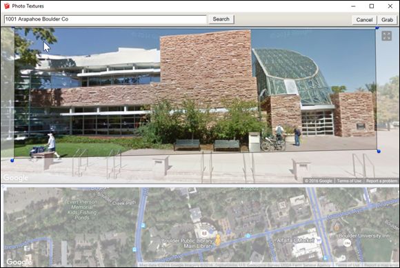
FIGURE 8-3: You can use the Google Street View imagery to photo-texture your model.
The photo textures you apply using Add Photo Texture are like any other photo textures in your model. You can edit the texture in exactly the same way, as we explain in the next section.
Editing your textures
After you successfully map an image to a face, you probably want to change the image somehow: Make it bigger, flip it over, rotate it — you get the idea. This is where the Position Texture tool comes in.
The Position Texture tool is actually more of a mode; we call it Texture Edit mode. Within this mode, you can be in either of two submodes. Their names are less important than what they do, so that’s how we describe them:
· Move/Scale/Rotate/Shear/Distort Texture mode: Use this mode to move, scale, rotate, shear, or distort your texture (surprised?). Technically, this mode is called Fixed Pin mode. You see why in a moment.
· Stretch Texture mode: Stretch Texture mode lets you edit your texture by stretching it to fit the face it’s painted on. If you want to map a photograph of a building facade to your model, this is the mode you want to use. In the SketchUp Help documentation, Stretch Texture mode is called Free Pin mode, in case you’re interested.
 You can edit textures only on flat surfaces; the Position Texture tool doesn’t work on curved surfaces. For details about working with textures and curved surfaces, see “Adding photo textures to curved surfaces ” later in this chapter.
Moving, scaling, rotating, shearing, and distorting your texture
The title of this section pretty much says it all — doing the aforementioned things to your texture involves Texture Edit mode, which is a little bit hidden, unfortunately. Follow these steps to move, scale, rotate, or skew your texture:
1. With the Select tool, click the face with the texture you want to edit.
2. Choose Edit ⇒ Face ⇒ Texture ⇒ Position.
This command enables (deep breath) the Move/Scale/Rotate/Shear/Distort Texture mode. You see a transparent version of your image, along with four pins, each a different color, as shown in Figure 8-4 . If all your pins are yellow, you’re in Stretch Texture mode. Context-click your textured face and select Fixed Pins to switch to the correct mode.
A quicker way to get to Texture Edit mode is to context-click the textured face and then choose Texture ⇒ Position from the context menu.
3. Edit your texture.
At this point, you can edit your texture in two ways: by using the options on a context menu or by dragging the colored pins.
Context-clicking your texture opens a context menu with the following options:
o Done: Tells SketchUp you’re finished editing your texture.
o Reset: Undoes all the changes you’ve made to your texture.
o Flip: Flips your texture left to right or up and down, depending on which suboption you choose.
o Rotate: Rotates your texture 90, 180, or 270 degrees, depending on the suboption you choose.
o Fixed Pins: When this option is selected, you’re in Move/Scale/Rotate/Shear/Distort Texture mode (Fixed Pin mode). Deselecting it switches you over to Stretch Texture mode, discussed in the upcoming section “Stretching a photo over a face .”
o Undo/Redo: Goes back or forward a step in your working process.
Dragging each of the colored pins has a different effect (refer to Figure 8-4 ):
o Scale/Shear (Blue) pin: Scales and shears your texture while you drag it. Shearing keeps the top and bottom edges parallel while making the image “lean” to the left or right.
o Distort (Yellow) pin: Distorts your texture while you drag it; in this case, the distortion looks kind of like a perspective effect.
o Scale/Rotate (Green) pin: Scales and rotates your texture while you drag it.
o Move (Red) pin: Moves your texture around while you drag it. Of all four colored pins, this one is the most useful. It's great for precisely positioning brick, shingle, and other building material textures in a model.
4. In your modeling window, click anywhere outside your texture to exit Texture Edit mode.
You can also press Enter or context-click and choose Done from the context menu.
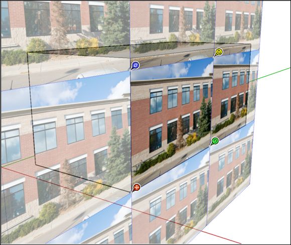
FIGURE 8-4: Dragging each colored pin does something different.
Stretching a photo over a face
Imagine a photograph printed on a piece of fabric that you can stretch until the photo looks the way you want and that you hold in place with pins. That's basically how Stretch Texture mode (also known as Free Pin mode) works.
Follow these steps to stretch your texture using the Position Texture tool’s Stretch Texture mode:
1. With the Select tool, click the face with the texture you want to edit.
2. Choose Edit ⇒ Face ⇒ Texture ⇒ Position.
A quicker way to get to Texture Edit mode is to context-click the textured face and choose Texture ⇒ Position from the context menu.
3. Context-click your texture and clear the check mark next to the Fixed Pins option. (Make sure that no check mark is next to it.)
You switch to Stretch Texture mode. Instead of four differently colored pins with little symbols next to them, you see four white pins. (The pins used to be yellow.)
4. Click and drag each pin to reposition it until your photo stretches over the face in a way you like.
If you’re repositioning a photo of a building, click a pin to pick it up, and then click to place the pin at a corner of the building, as shown in Figure 8-5 . Then, drag each pin to a corner of the face to stretch the photo.
If you need to, feel free to orbit, zoom, and pan around your model to get the best view of what you’re doing; just use the scroll wheel on your mouse to navigate without switching tools.
5. Press Enter to exit Texture Edit mode.
FIGURE 8-5: Place the pin at the corresponding corner (upper left to upper left, for instance) of the building in your photo.
If you don’t like what you see, go back and edit the texture again; you can muck around as many times as you like.
Scaling your model until the photo looks right
When you’re happy with the way your texture is stretched to fit the face, one of two things will be true:
· The proportions are correct. By this, we mean that the photo doesn’t look stretched or squashed. This is the case only if the face to which you applied the photo texture was already exactly the right size.
· The proportions aren’t correct. If the photo texture you just “tweaked” looks stretched or squashed, the face it’s on is the wrong size. No worries — you just need to adjust the whole face until the texture looks right. Better yet, if you know how big the face is supposed to be (in real life), you can stretch it until it’s correct.
Follow these steps to stretch a face until the texture looks right:
1. Use the Tape Measure tool to create guides that you can use to accurately stretch your face.
If you don't know how many feet wide your building is, take your best guess and see how the result looks. Chapter 3 explains how to use the Tape Measure tool and guides.
2. Select the face you want to stretch — or your whole model if you're just roughing out your model.
If your model is at a fairly early stage, it's easiest to select the whole kit and caboodle. Triple-click the face with the Select tool to select it and everything attached to it.
3. ![]() Choose Tools ⇒ Scale to activate the Scale tool. Or select the Scale tool on the toolbar.
Choose Tools ⇒ Scale to activate the Scale tool. Or select the Scale tool on the toolbar.
When the Scale tool is active, the SketchUp scaling box surrounds your model. Its 27 little green cubes (or grips ) and thick, yellow lines are hard to miss.
4. Scale your selection to the right size. (See Figure 8-6 .)
Use the Scale tool by clicking the grips and moving your cursor to stretch whatever’s selected (including your texture). Click again to stop scaling.
To scale something precisely using a guide, click a scale grip to grab it and then hover your pointer over the relevant guide to tell SketchUp that’s where you want to scale to. Click again to finish the scale operation.
FIGURE 8-6: Use the Scale tool’s grips to stretch your selection (texture and all).
It’s perfectly normal to want to keep modeling with your photo-textured faces; tracing a window and pushing it in a bit with the Push/Pull tool is one of the most satisfying things you can do in SketchUp. Flip ahead a few pages and take a look at the “Modeling on Top of Photo Textures ” section to discover everything you need to know.
Editing the pixels in a texture image
Perhaps there’s something in a photograph you’re using, and you don’t want it to be there. You can use Edit Texture Image to open the texture you’ve selected in an image-editing program, where you can edit the texture directly.
Follow these steps to use Edit Texture Image:
1. Context-click the texture in your model you want to edit and choose Texture ⇒ Edit Texture Image.
2. In the program that opens, make whatever changes you need to make.
Be sure not to change the proportions of the image — that can really mess things up.
3. Save (don’t Save As and change the filename) the image you’re editing and close it if you like.
4. Back in SketchUp, check to make sure your edits have been applied.
Which image-editing program actually opens depends on what you have installed on your computer; you specify which one to use in the Applications panel of the Preferences dialog box. For what it’s worth, most designers use Adobe Photoshop, but you can use whatever you have.
Need to radically reduce the size of your SketchUp model file? Context-click any textured face in your model and choose Make Unique Texture to create a copy of the texture you’ve selected and crop (trim away everything that isn’t visible) that copy according to the face it’s on. Why is this important? Just because you can’t see part of an image doesn’t mean it’s not there; SketchUp saves the whole photo with the model, even if you use only a little bit of it. In a complex model with dozens of photo textures, all that invisible, extra photo data adds up. Making your textures unique can make your models much, much smaller.
Adding photo textures to curved surfaces
Notice how the title of this section ends with surfaces and not with faces? That’s because (as you know by now) individual faces in SketchUp are always flat — no exceptions. When you see a non-flat surface, it’s actually made up of multiple faces. You can’t see the edges between them because they’ve been smoothed. Choosing View ⇒ Hidden Geometry exposes all curved surfaces for what they really are. Refer to Chapter 3 for a refresher.
How you go about mapping an image to a curved surface in SketchUp depends on what type of curved surface you have. With that in mind, curved surfaces fall into two general categories (see Figure 8-7 ):
· Single-direction curves: A cylinder is a classic example of a surface that curves only in one direction. In SketchUp, a cylinder is basically a series of rectangles set side by side. Most curved walls you see on buildings are the same way; they don’t taper in or out as they rise.
Another way to think about single-direction curves is to consider how they might have been made. If the curved surface you’re staring at could be the result of a single push/pull operation (such as turning a circle into a cylinder), there’s an excellent chance it’s single-direction.
For mapping an image to a single-curve surface, you can use the Adjacent Faces method; it works well and doesn’t stretch your image.
· Multi-direction curves: Terrain objects, saddles, and curtains are all prime examples of surfaces that curve in more than one direction at a time. They’re always composed of triangles — never basic rectangles.
To map an image to this type of curved surface, you must use the Projected Texture method. Skip ahead a couple pages to read all about it.
FIGURE 8-7: All curved surfaces are either single-direction (left) or multi-direction (right).
Please keep in mind that we totally made up names for the Adjacent Faces and Projected Texture methods of mapping images to non-flat surfaces. We had to call them something, and these sounded descriptive without seeming too technical.
The Adjacent Faces method
If you need to paint an image onto a surface that curves only in a single direction (such as a cylinder), you can use this technique. Follow these steps to find out how and take a look at Figure 8-8 to see the process in action:
1. Choose View ⇒ Hidden Geometry to turn on Hidden Geometry so you can see the individual faces in your model.
2. “Load” your cursor with an imported image.
Follow Steps 1-4 in “Importing images: Use your own photos ” (earlier in this chapter) to import an image as a texture.
3. Paint the leftmost sub-face entirely with the image.
Your curved surface is composed of sub-faces. Here’s how to paint the correct one:
1. Hover your loaded cursor over the lower-left corner of the sub-face farthest to the left. Don’t click yet.
2. When the image is oriented in the right direction, click once.
3. Click again on the upper-right corner of the same sub-face.
This places the image; it should be cropped on the right.
4. ![]() Select the Paint Bucket tool, hold down the Alt key (Command on a Mac), and click the first sub-face to sample the texture (image) you just placed.
Select the Paint Bucket tool, hold down the Alt key (Command on a Mac), and click the first sub-face to sample the texture (image) you just placed.
This “loads” your Paint Bucket tool with the texture.
5. With the Paint Bucket tool, click once on the face immediately to the right of the face you painted in Step 3.
If everything’s working correctly, the image you placed appears on the face you just clicked.
6. Keep painting sub-faces until you’re done.
Remember to work your way from left to right; skipping a sub-face messes up things. To fix a problem, just use Undo and keep going.
FIGURE 8-8: The Adjacent Faces method lets you map images to simple curved surfaces.
The Projected Texture method
For painting an image onto a complex curved surface, there’s no substitute for this method. Chunks of terrain are good examples of complex curved surfaces — bumpy, twisted, rippled, and multi-directional. If the curve you’re dealing with is more complicated than a simple extrusion, you need to use this image-mapping technique.
The key is to line up a flat surface with the curved surface to which you want to apply the photo texture. You then “paint” the flat surface with the texture, make it projected, sample it, and finally, paint the curved surface with the projected, sampled texture. Whew.
Follow these steps to get the basic idea (see Figure 8-9 ):
1. Create a flat surface that lines up with your curved surface.
You can use the Line tool and SketchUp’s inferencing system to draw a flat face that lines up with (and is the same size as) your curved surface.
2. Apply a photo texture to your flat surface and make sure that it’s positioned correctly.
For help, see “Adding photos to flat faces ” earlier in this chapter.
3. Context-click the textured face and choose Texture ⇒ Projected.
This ensures that the texture is projected, which is the key to this whole operation.
4. Select the Paint Bucket tool, hold down the Alt key (Command on a Mac), and click the projected texture to sample it.
This “loads” your Paint Bucket tool with the projected texture.
5. Without pressing anything on your keyboard, click the curved surface to paint it with the projected texture.
The pixels in the image likely look stretched in some places.
6. Delete the flat surface that you originally mapped the image to; you don’t need it anymore.
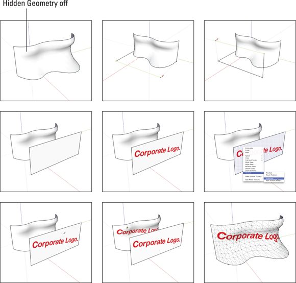
FIGURE 8-9: Mapping projected textures to curved surfaces is possible, but it ain’t easy.
If you’re trying to do this task on your own curved surface and things don’t seem to be working, your curved surface is probably part of a group or component. Either explode or double-click to edit the group or component before you do Step 5 and see whether that helps. Chapter 5 explains how to edit groups and components.
Modeling Directly from a Photo: Introducing Photo-Matching
The first time we saw SketchUp’s photo-matching feature in action, we giggled and clapped our hands like toddlers at a petting zoo. We're not ashamed of it, either. Sometimes technology that’s so useful, so unexpectedly satisfying, comes along, and you just can’t help yourself.
So what does photo-matching do? If you have a good photograph (or multiple photographs) of the thing you want to model, SketchUp’s photo-matching feature can help you create your model. This application is how 99 percent of modelers use this feature, and the technique we focus on in this section. (You can also match an existing model to a photo.)
You can edit any texture in your model — including ones produced by photo-matching — by opening them in image-editing software (such as Photoshop) directly from SketchUp. This trick is handy for taking out stuff you might not want in your photos, such as trees, cars, and ex-husbands. Take a look at the section “Editing the pixels in a texture image ,” earlier in this chapter, for all the juicy details.
Choosing a Match Photo-friendly image
Photo-matching works only on photographs of objects with at least one pair of surfaces that are at right angles to each other. Luckily, this includes millions of things you may want to build. But still, if the thing you want to photo-match is entirely round, or wavy, or even triangular, this method won’t work.
Here are tips for choosing a photo for this process:
· Watch out for lens distortion. When you take a picture with a wide-angle lens, some straight lines in the image bow a little bit, depending on where they are in the frame. Try to use photos taken with a normal or telephoto lens: 50mm to 100mm is a good bet.
· Make sure that the edges of two perpendicular surfaces are visible in the shot. You need to see planes that are at right angles to each other in order to use photo-matching properly.
· Shoot at a 45-degree angle if you can. Because of the way perspective works, your results are more accurate if you use a photograph in which you can see both perpendicular surfaces clearly; if one of them is sharply distorted, you have a harder time.
The following types of photos, illustrated in Figure 8-10 , work especially well with SketchUp's Match Photo feature:
· An interior view of a room in which a corner meets at a right angle
· An aerial shot
· An exterior view taken from a human vantage point and in which a corner (or corners) meet at a right angle
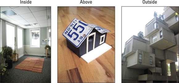
FIGURE 8-10: Choose the style that best describes your photograph’s camera position.
Modeling by photo-matching
The Match Photo feature helps you build a model based on a photograph. Here are two basic concepts:
· The process is iterative, not linear. Building a model using a matched photo entails going between drawing edges, orbiting around, drawing more edges, going back to your matched photo scene, and drawing yet more edges. Every photo is different, so the ones you work with will present unique challenges that you’ll (hopefully) have fun figuring out.
· Don’t forget the photo textures. By far one of the coolest features of photo-matching is the ability to automatically photo-texture your model’s faces by using your photograph as “paint.” It’s a one-button operation, and it’s guaranteed to make you smile.
Follow these steps to start building a model from a photo:
1. Choose Camera ⇒ Match New Photo.
A dialog box opens.
2. Select the image on your computer that you want to use and click the Open button.
The dialog box closes, and you see the image you chose in your modeling window. You also see a jumble of colorful techno-spaghetti, as shown in Figure 8-11 . Don’t worry — it’s all part of the photo-matching interface.
3. In the Match Photo panel, choose the style that matches your photograph: Inside, Above (for an aerial view), or Outside (for an outdoor view taken at ground level).
For the barn shown in this example, we selected Outside.
4. Click and drag the end points of the green perspective bars so that each bar lines up with edges in the photo that should be parallel to the model's green axis.
The tops and bottoms of windows are good candidates, as are rooflines, tabletops, and ceiling tiles. In our example, we align the green perspective bars with the barn’s roofline.
The following tips can help you position the bars correctly:
o Zoom in and out (using the scroll wheel on your mouse) to better view your photograph while you place your perspective bars. The more accurately you place the bars, the better things will turn out.
o Match your perspective bars to nice, long edges in your photograph; you get better results that way.
5. Click and drag the endpoints of the red perspective bars so that they line up with edges in the photo that should be parallel to the model's red axis.
The edges must be perpendicular to the first set of edges, or photo-matching doesn’t work. In our example, we align the red perspective bars to edges on the barn’s siding that are also perpendicular to the green perspective bars. You can see the result in Figure 8-12 .
6. Drag the axis origin (the little square where the axes come together) to a place where your building touches the ground and right at the intersection of two perpendicular edges, as shown inFigure 8-13 .
Setting the axis origin is how you tell SketchUp where the ground plane is. After you set the axis origin in the right place, notice that the horizon line, which is the horizontal yellow bar, lines up with the horizon in your photo.
As long as you place the perspective bars correctly, the horizon line bar typically takes care of itself. However, now you know what the yellow horizon line bar does in case you need it.
7. (Optional) In the Match Photo panel, set the grid spacing so that you can roughly scale your model to your photo.
In our example, we leave the Spacing option set to the default of 5 feet. We know the barn is about 20 feet tall. 4 gridlines are all we need to scale the model to the photo (because 4 × 5 = 20).
If you're photo-matching an arena or a skyscraper, you probably need to adjust the grid spacing so that the grid can scale to such a large width or height.
8. Click the Done button in the Match Photo panel.
When you click the Done button, you stop editing your matched photo. All the colorful lines and grips disappear, and you’re left with the photo you brought in, your model axes, and your thoughts. It may have seemed like a lot of magic, but what you did was pretty simple: You used photo-matching to create a scene (explained in Chapter 11 ) with a camera position and lens settings that match the ones used to take the picture that’s on your screen. In effect, you’re now “standing” exactly where the photographer was standing when the photograph was taken.
9. Select the Line tool and, starting at the axis origin, trace one of the edges in your photograph.
Make sure that you’re drawing in one of the three main directions: red, green, or blue. If you accidentally orbit so that your photo disappears, click the scene tab to see the photo again. (We talk a little more about orbiting as you draw in the tips that follow Step 11.)
10.Keep tracing with the Line tool until you have a rectangular face, watching the color of your edges as you draw.
You always want your lines to turn red, green, or blue when you’re starting.
11.Use SketchUp’s drawing tools to continue to trace the photograph in three dimensions.
In Figure 8-14 , you see two rectangular faces, one drawn on the green axis and the other drawn along the red axis.
Here are pointers for successfully tracing your photo with SketchUp’s drawing tools:
o Always start an edge at the end of an edge you’ve already drawn. Doing so helps to assure that your results are what you expect.
o Never draw an edge in midair. Okay — this is the same as the last one, but it bears repeating: When you draw edges based on other edges, you get the best results.
o To start, be careful not to orbit while you draw. You can zoom and pan all you want, though. If you orbit away from the vantage point you set up, your photograph will disappear, and you see only the geometry you’ve drawn, as shown in Figure 8-15 . You can easily get back by clicking the scene tab for your matched photo. The tab is labeled with the name of your photo at the top of your modeling window.
o After your model begins to take shape, orbit frequently to see what’s going on. You’ll be surprised what you have sometimes — tracing a 2D image in 3D is tricky business. Get in the habit of orbiting around to check on the results and draw certain edges. Click the matched photo scene tab to return to the proper view.
o Use other tools (such as Push/Pull and Offset) when appropriate. Nothing prevents you from using the full complement of SketchUp’s modeling tools. However, tracing the basic skeleton of a model with the Line and Eraser tools keeps the process simple.
o Pay attention to the colors. With a color photograph as an overlay, seeing what you’re doing can be tricky. Watch to make sure that you’re drawing the edge you intend to draw.
o Draw angles by connecting the dots. If you need to trace an edge in your photo that doesn’t line up with any of the colored axes (an angled roofline, for example), figure out where the endpoints are by drawing perpendicular edges and connecting them with an angled line, as shown in Figure 8-16 . You can delete the line or lines that you don’t need later.
o Show or hide your photograph. Doing so sometimes helps you see your work. The next section explains where to find the controls on the Styles panel.
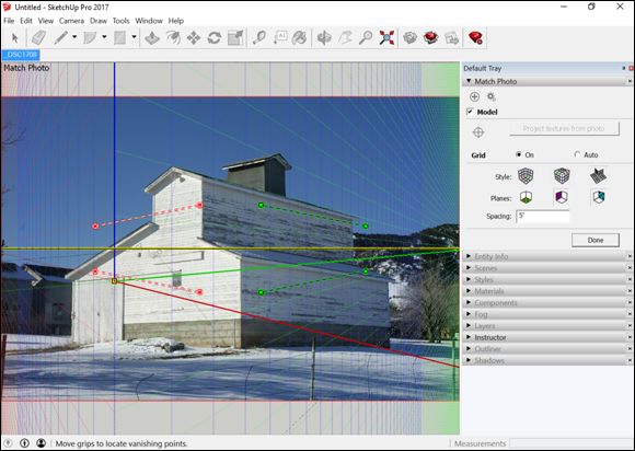
FIGURE 8-11: The photo-matching interface includes your picture, plus lots of other things.
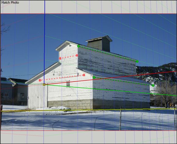
FIGURE 8-12: The perspective bars are aligned with the roofline and siding.
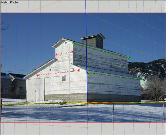
FIGURE 8-13: The axis origin is on a corner that touches the ground.
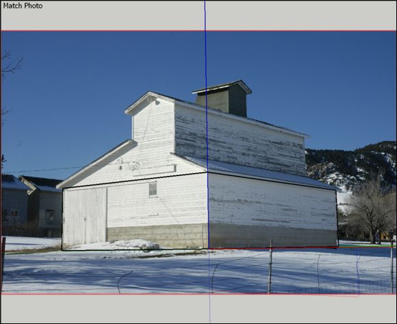
FIGURE 8-14: As you begin tracing your model, align your edges with the drawing axes to create basic shapes.
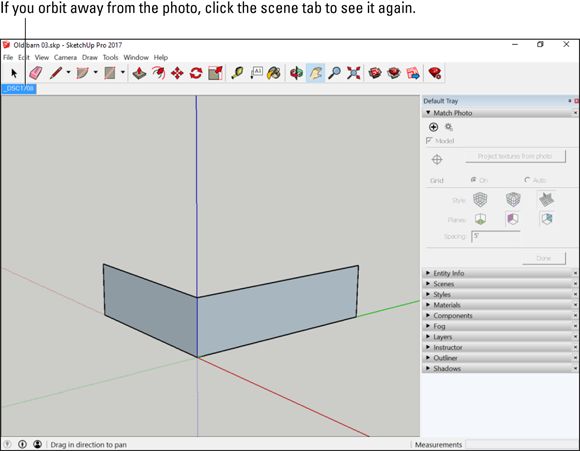
FIGURE 8-15: When you orbit, your photo disappears. Click the scene tab to see the image again.
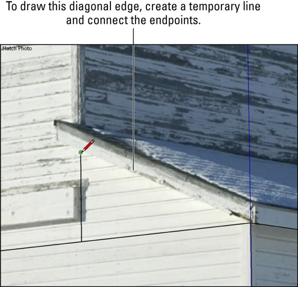
FIGURE 8-16: Draw a temporary line to create an edge for a roofline or other edge that doesn't align with a colored axis.
After you finish drawing your model, you can scale it precisely by using the Tape Measure tool. (Chapter 3 explains how.)
Making your matched photo reappear (or disappear)
After you match a photo to your model, the following tips are handy to know:
· Click the matched photo scene tab: When you create a new matched photo, you create a new scene. (You can read all about scenes in Chapter 11 .) Clicking a matched photo scene tab returns your view to the one you set up when you created (or edited) that matched photo. It also makes the associated photograph reappear — handy if you’ve orbited into another view.
· Manage photo visibility settings in the Styles panel: Deep, deep down in the bowels of the Styles panel, on the Edit tab, in the Modeling Settings section, you can control the visibility of your matched photo. Chapter 10 is where you find out about Styles.
Modeling on Top of Photo Textures
After you place a photo texture on the right face and in the right place on that face (yeah, we've been reading a lot of Dr. Seuss), you can use the information in your photograph to help with adding geometry to your model. It’s a great way to be roughly accurate without having to measure much, and the combination of photo textures and a few simple push/pull operations can be very convincing.
Making a texture projected
Modeling with photo-textured faces isn’t hard, but you have to take one critical step before you can do it: You have to make sure that your texture is projected.
Figure 8-17 shows what happens when you try to push/pull an opening in a photo-textured face: On the left, when the texture isn’t projected, the inside faces are painted with random parts of the texture, making your model look like a sticker-laden eye puzzle. On the right, when it is projected, note how the “inside” faces that the push/pull operation creates are a plain, easy-to-discern gray. The result is typically more appropriate for what you’re doing.
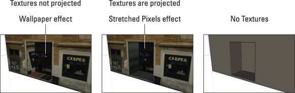
FIGURE 8-17: Pushing/pulling an opening in a textured face when the texture isn’t projected (left) and when it is projected.
Make sure that your face’s texture is projected before you start drawing on top of it. Happily, telling SketchUp to make a photo texture projected is just a matter of flipping a switch. Context-click the face with the photo texture and choose Texture ⇒ Projected from the context menu. If you see a check mark next to Projected, your texture is already projected; don’t choose anything.
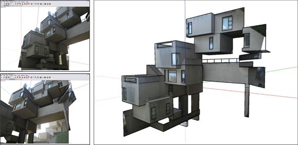
MAKING MULTIPLE MATCHES
If you have more than one photo of your modeling subject, you can have multiple matched photos in the same SketchUp file. Just get as far as you can with the first photo and then start again with the next by using the geometry you created as an “existing building.” See the section “Matching a photo to an existing model,” earlier in this chapter, and follow the steps to line up an existing model with a new photograph.
The following shows a model Aidan started to build of Habitat 67, in Montreal. He used two pictures to create two matches in the same SketchUp file. Making more than one photo match is a great way to build more of a model than you could see in a single picture.
Modeling with projected textures: A basic workflow
Follow these steps to get the hang of working with projected textures (and see the steps in action in Figure 8-18 ):
1. Make a basic rectangular box and then apply a photo texture to one of the side faces.
Check out the section, “Adding photos to flat faces ,” earlier in this chapter.
2. Context-click the textured face and choose Texture ⇒ Projected from the context menu.
Make sure that Projected has a check mark next to it.
3. Draw a rectangle on the textured face and push/pull it inward.
Notice the stretched pixels effect?
4. (Optional) Add other angles or features to your model.
Notice the angled face we created in Figure 8-19 .
5. Switch to the Paint Bucket tool, hold down the Alt key (Command on a Mac), and click somewhere on the textured face to sample the texture. (Your cursor looks like an eyedropper when you do this.)
This step loads your Paint Bucket with the projected texture.
6. Release the Alt (Command) key to switch back to the Paint Bucket cursor and then click the angled face once to paint it with the projected texture.
You see the stretched pixels effect here, too.
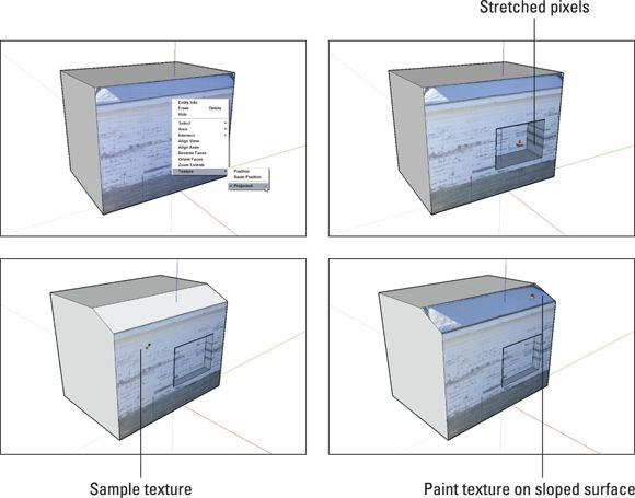
FIGURE 8-18: Working with projected textures.
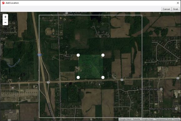
FIGURE 8-19: The area you frame with the pins is imported into your model as a geo-location snapshot.
Adding Geographic Data
When you add geographic data to your model (also called geo-locating your model), you give it a specific latitude, longitude, and cardinal orientation based on an address, cross streets, or other information. That doesn't sound like much at first, but here are three things geo-location enables you to do:
· Perform accurate shadow studies. For most designer-types, this is probably the biggest benefit of geo-locating a model. With a latitude, a longitude, and a cardinal orientation, SketchUp’s shadow engine can display crazy-accurate shadows for any time of day, any day of the year. You can find all the juicy details in the second half of Chapter 10 .
· View your model in Google Earth. After your model understands where on the planet it belongs, you can easily export the model file and send it to your copy of Google Earth. Flying from the Eiffel Tower to the Taj Mahal and then to your proposed new tool shed gives your design a level of seriousness that proclaiming, “Look what I’ve spent the last 37 hours working on!” to your spouse simply can’t match. It’s also impressive to clients.
The sections that follow outline the nitty-gritty steps for telling SketchUp where on Earth your model is (literally), looking at it in Google Earth, and saving it as a Google Earth file that you can share with other humans.
Geo-locating your model
Follow these steps to add a geo-location snapshot to your SketchUp file:
1. Make sure you’re online.
All geo-data is stored on far-flung servers; if you don’t have an Internet connection, you can’t use the geo-data.
2. Open the SketchUp file you want to geo-locate.
You can add a geo-location snapshot to your model anytime as you work on it. If you haven’t started modeling yet, it’s perfectly okay to add a geo-location to an empty file.
3. Choose File ⇒ Geo-Location ⇒ Add Location from the menu bar.
A new window that you may recognize opens: It’s a simplified version of Google Maps.
4. Find the area where you want your model to be located.
You can type an address into the search bar in the upper-left corner if you like. You can also just use your mouse or the controls on the left side of the window to navigate around. Scroll your mouse wheel to zoom; click and drag to pan.
When you’re zoomed in close enough, you see a white, 1 km x 1 km square: This is the largest snapshot you can import all at once. That’s still a very big area, so you probably want to keep zooming.
5. Click the Select Region button to display a cropping rectangle.
6. Drag the pins to specify the precise corners of your geo-location snapshot, as shown in Figure 8-19 .
Try to frame an area that’s just big enough to provide a base for your model. Importing too much terrain data can bog down your computer. You can always bring in more terrain data later.
7. Click the Grab button to add a geo-location to your SketchUp file.
The separate window closes, and a big, colorful rectangle appears in the middle of your model. That’s your new geo-location snapshot.
8. If you’re geo-locating a model you’ve built already, move it into position on the snapshot.
Use the Move tool (and maybe the Rotate tool) to pick up your model and place it where it belongs. You’re not done yet, though — you still need to make sure your model is vertically situated on the terrain. Follow these steps to do just that:
1. Choose File ⇒ Geo-location ⇒ Show Terrain to switch to the 3D version of your geo-location snapshot.
2. Select everything you want to move and use the Move tool to start moving; tap the up- or down-arrow key to constrain your move to the blue axis.
3. Sink your model into the terrain until it sits properly — avoid the dreaded floating model syndrome at all costs.
If you want to import another snapshot into SketchUp, you can. SketchUp automatically tiles all the snapshots you take to form a patchwork in your model. This feature is super-handy if you find that you didn’t get everything you needed the first time.
ALL ABOUT GEO-LOCATION SNAPSHOTS
When you import a geo-location snapshot, you access Google’s huge repository of geographic data. The snapshots are a lot more than pretty pictures. In addition to geo-locating the model's position, a snapshot has the following features:
· Everything is already the right size. Perhaps you take a snapshot of a football field; when you measure that football field in SketchUp, it is exactly 100 yards long. That’s because SketchUp scales your snapshot to the correct size as part of the import process.
· Snapshots look flat but contain terrain data, too. The snapshot that SketchUp imports is more than just a color aerial photo. The snapshot also includes a chunk of topography — terrain. The terrain is flat when you first import it because it’s easier to build on that way, but you can toggle between flat and 3D (not flat) views by choosing File ⇒ Geo-Location ⇒ Show Terrain. Don’t fret if you don’t see any difference when you flip between the views — you probably just chose a flat site.
Viewing your model in Google Earth
After you make (or simply position) a model on top of a geo-location snapshot, exporting the model so you can view it in your copy of Google Earth is a simple operation. You can also e-mail the KMZ file to all your friends. If you model for clients instead of friends, you can send the file to them, too.
When someone opens the KMZ file, Google Earth opens on his computer (if he has Google Earth), and he’s “flown in” to look at the model you made. Try sending directions to your next party this way; your friends will think you’re a genius.
Follow these steps to export a SketchUp model to a KMZ file:
1. In SketchUp, select File ⇒ Export ⇒ 3D Model .
2. In the Export Model dialog box that appears, choose where on your hard drive you want to save the KMZ file.
3. Give the file a name and select the KMZ file type.
4. Click the Export button to save your model as a KMZ file.
Working with Imported CAD files
On the SketchUp Spectrum of Fun, importing and preparing CAD files is located right between latrine digging and cat milking — it’s not something many folks look forward to doing. This section is a collection of tips and tricks Aidan has learned in his many years of dealing with other people’s CAD files.
Importing a CAD file into SketchUp Pro
This would probably be a great time to let you know (just in case you missed the heading right above this paragraph) that only SketchUp Pro can import 2D CAD files in DWG and DXF format; SketchUp Make doesn’t include this functionality.
Your CAD file may be one you made yourself, but more likely you’ve received one from someone else. In that case, the absolute best thing to do is to open it in the same software that created it. If you have an AutoCAD file, open it in AutoCAD and take a look at its layer structure. Make a copy of the file, delete everything you don’t need to bring into SketchUp Pro, and proceed from there.
Simple, right? But what if (like Aidan) you don’t have AutoCAD? That’s okay — most folks don’t. You’ll have a fair amount of cleanup work to do in SketchUp after you’ve imported the CAD data, but it’s manageable. The section after this one describes a series of things you can do to wrangle the drawing into shape before you can start modeling.
Actually importing CAD data into SketchUp Pro isn’t very complicated. Follow these steps, and you’ll do just fine:
1. Open a fresh, new SketchUp file.
You can’t just open a DWG or DXF file in SketchUp Pro; you have to import the data into an existing model. We strongly recommend starting with a new SketchUp file because most CAD files are super complex. Bringing all that complexity — thousands of edges and tons of layers — into an already-complex SketchUp model is just asking for trouble. Keep things separate and stay sane.
2. Choose File ⇒ Import.
The File Import dialog box opens.
3. Select AutoCAD files (*.dwg, *.dxf) from the Formats drop-down list.
For some reason, you have to tell SketchUp what kinds of files you want to import before it will let you select them on your file system.
4. Locate the CAD file (DWG or DXF) that you want to import and select it.
Don’t click Import just yet.
5. Click Options.
The DWG Import Options dialog box opens.
6. Set the Units to match the default measurement units of the CAD file you’re about to import.
If the CAD file is from someone in the U.S., there’s a good chance the units are Inches or Feet. Other countries (wisely) use the metric system. If you have no idea what units to choose here, so start with Inches and see whether that works.
7. Decide what to do about the other three options in the dialog box:
o Merge Coplanar Faces tells SketchUp to automatically combine adjacent faces that are coplanar into a single face. This can save you cleanup time if the CAD file you’re importing actually has faces in it, but CAD files rarely do. If you select this check box and your import fails (it happens), try deselecting it the next time.
o Orient Faces Consistently instructs SketchUp to do its best to make sure that the faces in your imported data (if there are any) are all facing the same way. Again, this might save you some cleanup time, but it also might throw a wrench into your import process.
o Preserve Drawing Origin is useful if you’ll be importing more than one CAD file into the same SketchUp model. You might do this if you’re importing multiple floor plans of the same building and you want them to line up.
8. Click OK to close the DWG Import Options dialog box.
9. Click Import … .
… and cross your fingers. With a few tries, you're usually able to import the CAD data. If you get a failure message, try again with a different Units setting in the Import Options dialog box (Step 6). If that doesn’t work, the file might have been saved in a CAD format that’s newer than the ones that your copy of SketchUp Pro can import. Contact the person who sent you the file and ask her to save another copy for you in an older CAD format.
10.Take a look at the Import Results dialog box to see where you stand.
If, after the import progress bar goes all the way to the right and the import itself is successful, SketchUp Pro will present you with a dialog box with statistics about what it imported and what it ignored. The simple version is that CAD layers, blocks (which translate to components in SketchUp), and edges of all sorts are importable. Text objects, dimensions, and hatches (of the sort that denote different materials) aren’t. When you’re satisfied, click OK and breathe a sigh of relief.
After you’ve gone through the CAD import process and SketchUp has plunked the resulting geometry into your model, make sure everything went according to plan: Measure a couple of things with the Tape Measure tool to see whether they’re the sizes you expect them to be. Doorways are a good place to start; if you measure one and it’s many times smaller or bigger than it should be, your Units (in Step 6 of the preceding steps) were set wrong. Close the file, open a new one, and try again.
Cleaning up imported CAD data
Most of the time, your imported CAD file looks something like the mess shown in the top image of Figure 8-20 . Walls, annotations, grid lines, and other stuff are all jumbled up, and it seems like you’re going to have to spend the rest of the week deleting edges. Probably not, actually — the following sections explain improvements you can make.
Switch to a style that’s easier to read
If you’re using a display style that includes lots of edge embellishments (such as Profiles, Extensions, and Endpoints), dense geometry of the sort in most CAD drawings looks like your model received an unwelcome visit from the Mascara Fairy. Yuck. Use the Styles panel to apply a style that’s plain and simple. We recommend either Shaded or Shaded with Textures, both of which you can find in the Default Styles collection. You can read all about styles in Chapter 10 . Figure 8-20 shows what a difference a style can make.
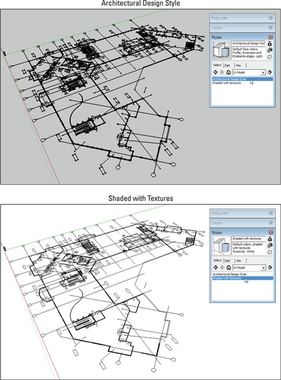
FIGURE 8-20: Applying a simple display style to a model with imported CAD data makes it a lot easier to work with.
Turn off layers you don’t need
Most of the drawing symbols and other annotations you brought into SketchUp aren’t things you need, at least right away. The simplest and safest way to get rid of them is to turn off their layers. Remember that SketchUp Pro also imports all of the layer information associated with the CAD data you brought in; now’s the time to use all of that complexity to your advantage.
Follow these steps to identify and hide the stuff you don’t need:
1. Open the Layers panel.
CAD files usually come with dozens of layers. Make the Layers panel nice and big so you can see more of them.
2. Open the Entity Info panel.
The Entity Info panel tells you which layer a selected entity is on.
3. Context-click any part of the imported CAD drawing and choose Edit Component.
As long as your model contains at least one entity when you do a CAD data import, SketchUp Pro automatically puts all the imported geometry into a single component. Whatever you do, try not to explode this component — you find out why later on in this chapter.
4. Select an entity that you don’t want to see right now.
In Figure 8-21 , a grid line that we don’t think we’ll need for awhile (or at all) is selected.
5. Look at Entity Info to see what layer contains your selected entity.
In this case, the selected grid line is on layer A-GRID. Okay, maybe we didn't need Entity Info to tell us that.
6. Find the offending layer in the Layers panel and turn it off.
In the second part of Figure 8-21 , switching off the A-GRID layer temporarily hides all the entities on that layer. Better already! If you’re positive you won’t need the contents of a particular layer, you can delete it altogether. Rebecca loves throwing out unneeded stuff, digital or otherwise, but Aidan's the kind of person who holds onto things (and has the basement to prove it).
7. Repeat Steps 4-6 for all of the entity types you want to hide.
This part of the cleanup process is pure SketchUp catharsis. It takes time, but the results are immediately visible. The last part of Figure 8-21 shows the result of hiding a bunch of layers.
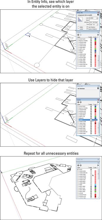
FIGURE 8-21: Select things you don’t need and hide the layers they’re on.
Of course, you can also dive right into the Layers panel and start turning off individual layers, especially if you know what entities they contain. The preceding steps are useful for situations where layers aren’t named descriptively or for when you’re overwhelmed and don’t know where to begin.
Modeling on top of imported CAD data
So you’ve successfully imported a CAD drawing and stripped down its style and visible layers to make it more manageable. Kudos — it’s time to start having some fun. Building a 3D model based on underlying (literally) CAD linework can be a surprisingly Zen experience if you follow one simple rule:
Keep the imported CAD data isolated inside of its own component and build your model on top of it. Don’t be tempted to use the imported edges to create faces directly.
Here are three reasons why:
· CAD data is almost always full of gaps. Lines that should extend all the way to their neighbors are sometimes short by tiny, invisible amounts, meaning you’ll spend hours drawing edges and trying to figure out why faces won’t appear where you want them to.
· CAD lines that should be parallel to one of the colored axes often aren’t. Think that edge is parallel to the red axis just because it looks like it might be? Not necessarily. Blithely turning imported edges into faces and then pushing/pulling them into 3D geometry is like building a house on quicksand; things get wonky quick.
· Imported CAD drawings aren’t always flat. Sometimes different parts of your imported linework are located at slightly, maddeningly different heights. We're talking thousandths of an inch — not enough to notice initially but certainly enough to mess up your work.
Instead of trying to use the imported edges as part of your 3D model, use them as references for new geometry that you draw on top of them. Tracing the imported geometry doesn’t take as much time as you’d think, and the result is a model whose geometry is far more accurate and predictable. The following two sections talk about strategies for “tracing” imported CAD content.
Modeling straight, vertical walls based on imported CAD edges
There’s a technique for modeling simple walls and other straight elements on top of imported CAD linework that’s so simple and enjoyable , that audiences regularly applaud when Aidan demonstrates it. The credit for this method goes to our friend (and colleague) Mike Tadros.
Before you get started, make sure you’re not editing the component that contains your imported CAD linework. Remember that you’re using the CAD drawing as a reference underlay for your own 3D modeling activities. You’ll be working “on top” (outside) of the component.
The Push/Pull tool is the hero of this method. Follow these steps (and see Figure 8-22 ) to model a straight wall based on edges in an imported CAD drawing:
1. Use the Axes tool to line up the colored modeling axes with the wall you’re about to model.
If the axes are already parallel to the wall, you can skip this step. If not, just choose Tools ⇒ Axes and line up the modeling axes with an edge in the CAD drawing that represents the wall you’re working on. If you're not familiar with the Axes tool, “Matching a photo to an existing model” earlier in this chapter walks you through an example of aligning the axes with a model.
2. Draw a rectangle next to the wall.
It doesn’t matter how big it is; you’ll see why in a moment.
3. Use the Push/Pull tool to extrude the rectangle up to the height of the wall you’re modeling.
If you don’t know it just yet, just guess. It’s easy to change this later.
4. Use the Push/Pull tool to extrude the box you just made so that it’s flush with one side of the wall.
If you drew the rectangle in Step 3 to the outside of the wall, push/pull the face so it’s flush with the inside of the wall. (See Figure 8-22 .)
The key to this step is pure SketchUp Inferencing 101: Click to start pushing/pulling, hover your pointer over the edge (or its endpoint) that you’re aiming for, and then click again to stop pushing/pulling. You’re using the imported CAD edge as an inferencing reference for your tool. It’s cake after you’ve done it once or twice.
5. Use the Push/Pull tool to make the opposite face of the box flush with the other side of the wall.
See what’s happening? You’re using the Push/Pull tool and carefully chosen inferences to turn the box into the wall.
6. Push/pull the ends of the 3D wall so they match the underlying drawing.
We told you this was fun.
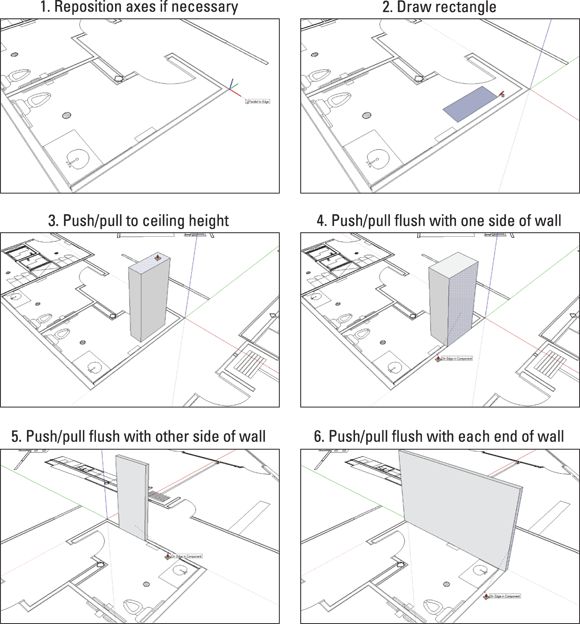
FIGURE 8-22: Modeling a simple wall based on a couple of edges in an imported CAD drawing.
What happens when walls meet up at corners? Well, that can happen at right angles (which is common) or at other angles (which isn’t uncommon).
MODELING RIGHT-ANGLED WALLS
For 90-degree corners, all you have to do is draw a rectangle on the inside face of your wall and use the Push/Pull tool to extrude it out. After that, use the same tool to make it flush with the edges in the CAD drawing. Figure 8-23 provides a visual.
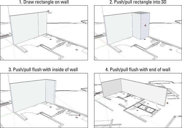
FIGURE 8-23: Use the Rectangle and Push/Pull tools to model walls that meet at right angles.
MODELING WALLS THAT MEET AT NON-RIGHT ANGLES
If you’re dealing with a corner that isn’t 90 degrees, you can proceed in a few different ways; using the Intersect Faces tool is a great place to start. The following steps (and Figure 8-24 ) elaborate on the technique:
1. Model each straight wall segment independently but don’t overlap their ends just yet.
Follow the steps in the section “Modeling straight, vertical walls based on imported CAD edges ,” a few pages earlier, to build each wall so it’s parallel with the CAD edges to which it corresponds. Don’t worry about the two wall ends that will eventually meet; keep them apart for now.
2. Use the Push/Pull tool to extend each wall well past the point at which it should meet the other.
You’re modeling something that looks like an X from above.
3. Select the inside and outside faces of each wall.
You should have a total of four faces selected.
4. Choose Edit ⇒ Intersect Faces ⇒ With Selection.
This action tells SketchUp to draw an edge wherever two faces intersect. If you had four faces selected, you should now have two new edges.
5. Use Push/Pull to push away the wall segments you don’t need.
Pushing their top faces all the way down to their bottom faces makes them disappear.
6. Use the Eraser tool to get rid of any extra edges.

FIGURE 8-24: Use Intersect Faces to model walls that form non-90-degree corners.
Modeling curved and irregular forms from CAD data
For rectilinear walls, stairs, and other shapes, SketchUp’s Rectangle and Push/Pull tools are rock stars. Rounded forms (such as concrete patios and castle turrets) and irregular lines (such as riverbeds and Frank Gehry buildings) call for other, more drastic measures.
The following steps give a general example dealing with features in your CAD file that aren’t worth painstakingly tracing with the Line tool but which need to appear in your SketchUp model. In these situations, you can rely on the handy Paste in Place command:
1. Dive into the component that contains the imported CAD linework.
By “dive into,” we mean edit it, which you can do by double-clicking it with the Select tool.
2. Select the edges you want to reuse.
3. Make a group out of the edges.
Choose Edit ⇒ Make Group to do this. Grouping your selection accomplishes two things: Grouping makes reselecting it easier (in case things go awry), and it keeps things nice and separate for the next couple of steps.
4. Choose Edit ⇒ Copy.
5. Stop editing the CAD linework component.
You can exit a component (or a group) by double-clicking with the Select tool somewhere outside its bounding box.
6. Choose Edit ⇒ Paste in Place.
Voilà! The edges in question are now a part of your model, and (thanks to Step 3) are quarantined from the rest of your geometry by means of a group.
For shapes that are made up of simple arcs (segments of circles), your best bet is to try to re-create them by using SketchUp’s own Arc tools. Why not just use the Paste in Place method (described in the preceding steps) to copy them? For arcs, it’s nice to have control over their number of sides, and drawing them from scratch is the only way to do that.
Follow these steps to accurately trace an arc from underlying CAD linework (see Figure 8-25 ):
1. Draw an edge that’s perpendicular to one of the arc’s line segments, heading in the direction of the arc’s center point.
You can use SketchUp’s Perpendicular linear inference to help you draw a perpendicular edge. This is the first step in figuring out the precise location of the arc’s center point.
2. Repeat Step 1 for another of the arc’s line segments, crossing your new edge over the one you just drew.
The point at which these two edges intersect is the center point.
3. Erase two of the edges that you just drew, leaving a small V that points to the arc’s center point.
Look at the third image in Figure 8-25 to see which two edges I’m referring to.
4. Choose Draw ⇒ Arcs ⇒ Arc to activate the Arc tool.
What is now called 2 Point Arc used to be SketchUp’s only Arc tool; it works by first setting endpoints and then setting a bulge. The new(ish) Arc tool, which is called simply Arc, lets you start by defining a center point; this is much more useful for situations like the one you’re in now. If you have SketchUp 2014 or later, you have this new Arc tool.
5. Click once to set the center point of your new arc.
This is, of course, at the tip of the V you drew in Step 3.
6. Complete the arc by clicking to set each of its endpoints.
7. (Optional) Change the number of edge segments in your new arc.
Before you move onto anything else, type the number of segments you want, followed by the letter s , and then press Enter. Most likely, you want more than the default 12 segments on arcs that represent major features in your design.
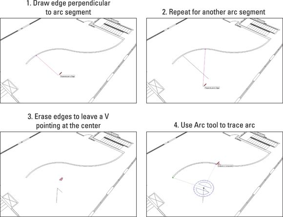
FIGURE 8-25: The Arc tool lets you easily draw arcs with a given radius.
All materials on the site are licensed Creative Commons Attribution-Sharealike 3.0 Unported CC BY-SA 3.0 & GNU Free Documentation License (GFDL)
If you are the copyright holder of any material contained on our site and intend to remove it, please contact our site administrator for approval.
© 2016-2026 All site design rights belong to S.Y.A.