SketchUp For Dummies (2017)
Part 2
Modeling in SketchUp
Chapter 9
3D Printing with SketchUp Models
IN THIS CHAPTER
![]() Dividing your model into layers
Dividing your model into layers
![]() Using SketchUp files for 3D printing
Using SketchUp files for 3D printing
![]() Preparing a SketchUp model for 3D printing
Preparing a SketchUp model for 3D printing
![]() Knowing your 3D printers
Knowing your 3D printers
![]() Going beyond basics with joints and motion
Going beyond basics with joints and motion
Seeing your masterpiece in SketchUp is cool. You can twist and turn and view it from every angle. But wouldn’t the world be so much cooler if you could hold your creation in your hands?
This chapter talks about using SketchUp with a 3D printer.
To follow along with this chapter, you need a working understanding of SketchUp and its tools. We assume you’ve heard about 3D printers and are curious to learn more. The focus is on desktop 3D printers, the most common class of 3D printers on earth. You get a look at 3D printing technology in general and touch briefly on a few types of professional machines.
Most of this chapter discusses guidelines, methods, and tools to help you modify your SketchUp models to be 3D printed. We also point out a few limitations of 3D printers, and how you can work within them.
Building Up a View of 3D Printing
It may sound like magic, but 3D printing is a process that uses the 3D information from your SketchUp model to build a physical version of that model in the real world. It’s science fiction come true.
3D printing got its start as the hot new technology of the mid-1970s — and spent 35 years stuck as the high-priced plaything of prototyping engineers and the lucky people who build fighter jets. And that’s where it stayed until the first DIY desktop 3D printers appeared in 2009. Overnight, the cost of a 3D printer fell from $500,000 to $500. What was once the coveted technology of the chosen few is now found on the desk of any well-equipped designer, engineer, or model maker.
Building a Model in Layers
There are many different 3D printing technologies and manufacturers, but they all use a process called additive manufacturing: An object is built from thin horizontal slices of material, with each new layer extruded slightly above the previous layer and then fused to it. Layer by layer, the printer builds up the object until it's finished.
Supporting layers from below
SketchUp’s world is an amazing place where you can rapidly build a 3D model while ignoring little things like the laws of physics. An object being 3D printed, however, is subject to all the forces of the physical world, including that pesky omnipresent one, gravity. New layers can’t be printed floating in open space; they need to have something below them.
 The need to support each layer is the most important guideline to keep in mind while you’re designing objects for 3D printing. You can use either of two strategies to support new layers as you’re printing objects:
· Use the 3D printer’s support-material function, which creates a secondary structural lattice around the part. The lattice holds up any layers that would otherwise be free-floating in space. Support material may be dissolvable after printing or have to be manually removed with fingers and tweezers, depending on your type of 3D printer. Either way, removal of support material can become the most labor-intensive part of 3D printing; it also increases the amount of materials used and the time it takes to print the object.
· Design and print your parts in a way that limits the conditions that allow unsupported layers to exist. Smooth transitions and sweeping curves not only look awesome; they can also be easily printed without resorting to the use of support material.
Designing to avoid support material
With a little forethought, you can avoid the use of support material entirely by adhering to a few basic guidelines:
· Think about your parts orientation. Orient the part so that it prints with the smallest number of overhangs. This may mean printing your object upside down or on its side. The capital T in Figure 9-1 could be printed standing upright, but laying it on its back allows it to print much faster — without support material.
· Try rethinking your angle. Most printers can print a slope between 45 and 60 degrees from vertical without using support material. Keep this limit in mind as you design. Chamfers and fillets are great for supporting features and smoothing out rough transitions. In Figure 9-2 , a chamfer turns a part with an unsupported overhang into an easily printable part. As an added bonus, fillets and chamfers make your part stronger by eliminating stress points.
· Consider breaking your object into multiple prints. The sphere in Figure 9-3 could be printed using support material, but it will print faster and with less cleanup if you split it in half and attach it back together afterwards. Later in the chapter, you learn about systems to make the parts lock together quickly.
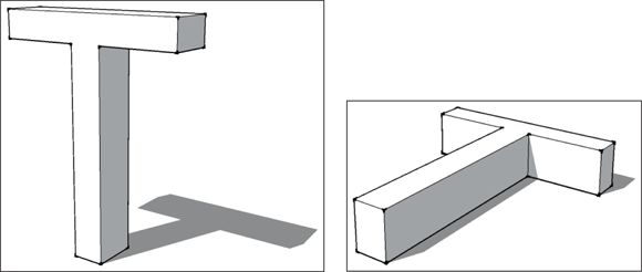
FIGURE 9-1: Re-orienting a part can make it print faster and leave less support material to clean up.
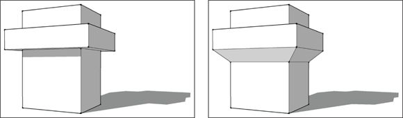
FIGURE 9-2: A chamfer can turn an unprintable 90-degree angle in to a printable 45-degree one.
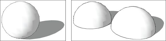
FIGURE 9-3: Often a subdivided part is faster and cleaner to print than a part printed all at once.
Bridging
Bridging is a feature on 3D printers that lets you print a structure across a gap without using support material. To bridge a gap, the structure being printed must be parallel to the build platform and have a secure point of attachment on either side, as with the top of the door frame shown in Figure 9-4 . The printer will attach plastic to one side of the gap and stretch a line across to the other side. The process is repeated until the gap is filled. Future layers are printed on top as usual.
FIGURE 9-4: When is a door frame a bridge? When it’s 3D printed.
Preparing a SketchUp Model for 3D Printing
The longer you work on a SketchUp model, the more it tends to fill with illogical intersections, free-floating cantilevers, and other quick shortcuts. When you’re making an image or walkthrough, these are minor trade-offs that help get a big job quickly. Drawing something that looks right on the outside in SketchUp doesn’t necessarily mean it can be 3D printed with one click of a button. A 3D printer can’t interpret that mishmash of geometry to guess what you were really thinking.
In this section, you discover how to clean up that SketchUp madness and make it into a 3D printable object. The cleanup process uses tools discussed in earlier chapters, but the way you use these tools differs. Cleaning up a messy SketchUp model can look like a daunting task when you start. Remind yourself that it’s just like eating an elephant: Divide the job into manageable chunks and work on them one at a time … even if the trunk can be a bit chewy.
Before you start cleaning up geometry to make your model 3D-printable, make sure you’ve saved a separate copy of your SketchUp file, just to be safe.
Peeking inside a model
Although you can use the Section Plane tool to create sectional views through your model, this awesome tool has another use: It can show you what’s going on inside your model’s geometry. 3D printers see a SketchUp model as a series of 2D horizontal slices. Figure 9-5 moves the Section Plane through the model horizontally to show what the 3D printer is going to see.
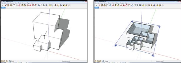
FIGURE 9-5: Using a section plane to look at all overlapping parts that make up your model.
To get a watertight solid object, all groups need to be combined into one, and all that extraneous geometry has to be eliminated from the model. Chapter 11 discusses the Section Plane tool in detail.
Knowing what makes a solid model
To 3D print your parts successfully, they need to be solid objects, or as close to solid as possible. No missing or extra faces, overlapping sections, or extraneous bits allowed. Your SketchUp model needs to describe all aspects of the outer surface of the shape. For example, to print an egg, a SketchUp model would need to describe 100 percent of the outside of the egg’s shell. That’s not as simple as it sounds.
A solid model that's 3D-printable meets the following criteria:
· The model walls have a thickness. Zero thickness = Zero printing. A wall that is a single face has a thickness of zero and will not print. You need to make sure all the walls have some thickness.
· The model has only an outer surface. In SketchUp, you can create a model quickly (in the abstract, anyway) by pushing parts through each other and building revisions on top of old geometry. To your 3D printer, however, such models are an illogical mess that would make M.C. Escher cry. Your 3D printer doesn’t stand a chance. You’ll need to clean everything up so that only the outer surface remains. Fortunately, SketchUp tools and extensions discussed later in this chapter can help.
· Groups and components are merged. Chapter 5 explains groups and components, and how to use them to keep your SketchUp model organized as you work. Groups and components are great for keeping parts from sticking together as you work, but to make your SketchUp model a solid shell that can be 3D printed, you need to merge everything together.
 Before you start exploding things and sticking them together, spend a moment thinking about how you want your actual 3D printed model to work. For most projects, you need to merge all your groups and components into one printable object before exporting your model from SketchUp. For larger projects, think about assembling the blocks into sections that you can 3D print and attach together later.
The upshot is that 3D printers aren’t very smart. If you make them guess what your part should look like, they will usually guess wrong. Figure 9-6 is a testament to the carnage.
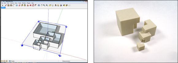
FIGURE 9-6: This poor print never stood a chance.
Using Solid Tools to combine groups
Chapter 6 explains how to use SketchUp’s Pro’s Solid Tools to perform Boolean operations. Solid Tools are great for unifying groups made up of simple solid parts. They can save significant time. Unfortunately, complex shapes cause the Solid Tools to act unexpectedly — and, after multiple iterations, to break down.
In Figure 9-7 , Solid Tools had no problem intersecting several simple cubes together, but adding a complex shape to the object caused the tools to break down. The accompanying sidebar takes a closer look at why this happens.
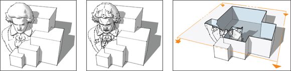
FIGURE 9-7: Booleans are great for simple things. But don’t rely on them for complex cleanup.
WHAT’S WRONG WITH SOLID TOOLS?
You may have been looking at the Outer Shell button in the Solid Tools menu and thinking, “Wow, making this into one outer shell is going to be easy.” So you decided to save your work, select your whole model, and click Outer Shell. Oops. (Come back when you're done screaming.)
In the discussion of Solid Tools in Chapter 6 , you find out that they are also called Boolean operations. Boolean operations started out as computer programming tools that help sort and manipulate data. In the early days of computer graphics, programmers used Boolean operations to work directly with the data that makes up 3D models. Boolean operations still exist in every piece of 3D modeling software today. If you take a class in 3D Modeling, they’ll be the first thing you’ll learn, and then you’ll be told to never use them ever again.
The problem is Boolean operations are the blunt instruments of 3D. They work within a narrowly defined set of parameters, and are notorious for the way they indifferently modify geometry. After a few uses, the damage caused by the tool itself starts to compound, and the model becomes too garbled for the Boolean to interpret again. Basically, after being confounded by the sum total of its own mistakes, it gives up in failure. Outer Shell is trying to run a whole series of Boolean operations at once, and if your model is made up of anything except simple shapes, those operations won’t succeed.
Unfortunately, cleaning up your model just isn’t going to be single-click simple.
CleanUp3 and Solid Inspector2
Two tools from the SketchUp Extension Warehouse are essential for 3D printing: CleanUp3 and Solid Inspector2 , both created by Thomas Thomassen.
CleanUp3 checks and simplifies the geometry of your SketchUp model. It combines multiple faces, eliminates extraneous data, and erases any lines that don’t make a face. Two of the most useful CleanUp3 options are Erase Duplicate Faces and Repair Split Edges, which can be enabled in the CleanUp3 menu. Duplicate faces and split edges are errors that inevitably appear in your model as you work in SketchUp, and they drive 3D printers nuts. Both errors are hard to recognize and repair manually.
CleanUp3 is also great at simplifying STL files (3D-printable files) you import into SketchUp. In Figure 9-8 , which shows the triangulated data you get from an imported STL file, the faces have been broken into hundreds of triangles. By removing that triangulation, CleanUp3 makes files downloaded from 3D printing communities (such as Thingiverse at www.thingiverse.com ) easier to edit in SketchUp.
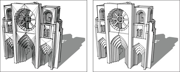
FIGURE 9-8: An imported STL file, before and after running CleanUp3 .
Solid Inspector2 finds and highlights problems that are preventing your model from being a solid shell, and we can’t overemphasize its usefulness. It highlights problem areas and helps you automatically move from one error to next, making repairs much faster (see Figure 9-9 ). It’s a tool that everyone using SketchUp for 3D printing should have.
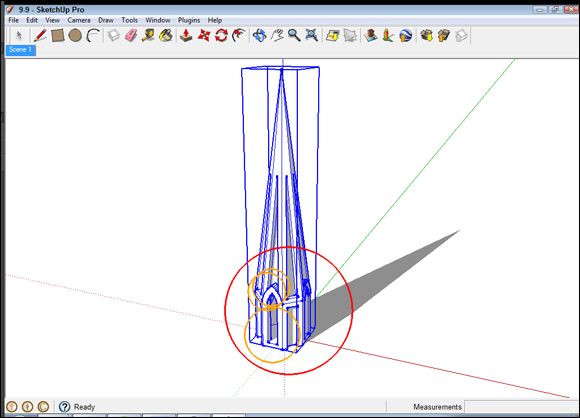
FIGURE 9-9: Solid Inspector2 is great at finding problems that need a quick fix.
As you work on your model, get in the habit of running CleanUp3 periodically. Run Solid Inspector2 before you export from SketchUp to 3D print. It will catch any errors that would cause the print to fail.
Combining groups with Intersect Faces
An alternative way to assemble your groups into one object is to use the Intersect Faces command, introduced in Chapter 4 . For 3D printing, Intersect Faces can eliminate overlapping geometry and leave behind a solid object. You can use Intersect Faces on very complex objects and groups that aren’t already solid.
In a complex model, isolate and work on one small part of the SketchUp model at a time, making each section into one solid part. Repeat the process on those sections until you have one solid model. The following steps outline this process in more detail:
1. Select the groups you want to combine and group them together.
Your original groups are now subgroups that exist together inside a new group.
2. Choose Edit ⇒ Intersect Faces with Context.
Doing so opens your new group and selects all the subgroups, drawing lines at all the places that groups intersect. These new lines of intersection exist outside the subgroups and aren’t stuck to anything yet, as shown in Figure 9-10 .
3. Select the lines of intersection and copy them by choosing Edit ⇒ Copy.
4. Open each of the subgroups and paste the lines of intersection into them, using Edit ⇒ Paste in Place.
Figure 9-10 shows the procedure.
5. Open each subgroup and erase all the areas of overlap beyond the lines of intersection.
Work deliberately, moving back and forth between the subgroups to make sure you’re erasing the right areas.
6. Back in the main group, select all the subgroups, context-click the selection, and choose Explode on the menu that appears.
You end up with one outer shell of an object in its own group. Figure 9-10 shows this result.
7. Run CleanUp3 on the new part and use Solid Inspector2 to check for any accidental holes.
Individual faces and short line segments can get lost during this process. You may need to make minor touch-ups with the Line tool.
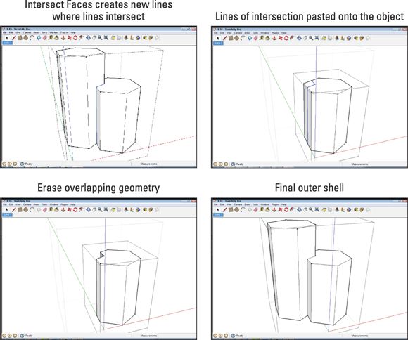
FIGURE 9-10: Erase overlapping geometry to create an outer shell.
Checking a model's normals
From a highly technical computer-science perspective, every face in your model has two sides: an inside and an outside. The two sides are set apart by a bit of data called the face’s normal .
SketchUp is smart enough that it doesn’t matter how the normals (also known as the front and back) are oriented; both sides are treated the same. 3D printers aren’t that clever; they need to have all the normals oriented so the outsides are pointing out and the insides are pointing in.
To check your model’s normals, you’ll need to look at it styled with SketchUp’s default texture. Choose View ⇒ Face Style ⇒ Monochrome to hide any colors or textures you’ve added to the model and see the default material. (Chapter 10 covers styles in detail.)
Any faces that are shaded the default blue have reversed normals. These faces will need to be corrected, or the 3D printer will see them as missing.
· To correct a single face, context-click the face and select Reverse Faces from the menu that appears.
· To correct several misaligned faces, context-click one of the faces that is white and select Orient Faces. Doing so flips all the faces in the model to match the view shown in Figure 9-11 .
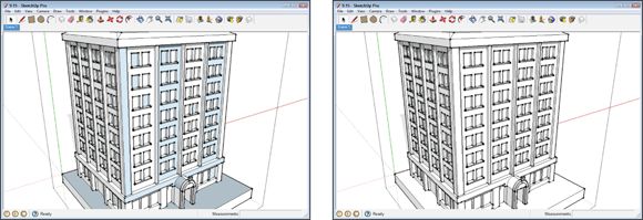
FIGURE 9-11: A correct normal is a happy normal.
If the Orient Faces tool causes everything to flip randomly, it’s a sign that you have extraneous faces inside your model. Use the Section Plane tool to look inside, find the face, and erase it.
Checking your model's size
Every 3D printer has a minimum and maximum size of object it can build, as shown in Figure 9-12 . These sizes are usually set by the size of the tool printing the material and by the overall size of the printer. To build something bigger, you have to get creative. To build something smaller, you’ll need a more expensive 3D printer.
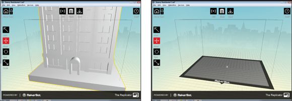
FIGURE 9-12: Too big and too small. There is something there on the right; it’s just very small.
Too small to print
In the SketchUp world, you can design a skyscraper small enough to fit on the head of a pin, but the 3D printer can’t print it. Every 3D printer has a minimum size for what it can build; anything smaller than that won’t be printed. You find these values listed as Minimum Feature Size and Minimum Wall Thickness. Feature Size and Wall Thickness can turn into stumbling blocks when you’re trying to 3D print a SketchUp model that was constructed at full size and then scaled down.
· Minimum Wall Thickness tells you how thin a freestanding piece of geometry can be and still be printed. That thickness is typically between 1.0mm and 0.5mm.
· Minimum Feature Size is the smallest size that a feature can be on the surface of the object that will be printed. It’s typically between 0.7mm and 0.2mm.
If you're modeling a small object for 3D printing, create the model in small units, such as millimeters, from the beginning. To set or change the default units in your SketchUp model template, choose Window ⇒ Preferences (SketchUp ⇒ Preferences on a Mac) and select a template that uses millimeters. You can also adjust the default units in the Model Info window by choosing Window ⇒ Model Info and selecting the Units option on the left.
Too big to print
The biggest object you can 3D print at one time is set by the printer’s build volume. If your model won't fit in the build volume, you have to either scale your object down, or print it in parts. The next section talks about how to split up a model so you can print it in parts.
Although the maximum size of any single part is limited by the size of your 3D printer, the size of what you can 3D print is limited only by your creativity and patience. A man in New Zealand is 3D-printing himself an Aston Martin, one 6-inch cube at a time.
Here are some handy hints for making best use of build volume:
· The build volume, or envelope, is given by manufacturers as measurements of X, Y, Z. X and Y are the width and depth of the build surface; Z is the maximum height.
· It’s helpful to create a representation of your 3D printer’s maximum build volume in your SketchUp model. Make a translucent block representing the maximum build volume and check to see whether your SketchUp model or its components will fit inside that volume.
· A 3D printer’s build platform is much longer diagonally than it is on any one side. To take advantage of the extra length, rotate long parts so they stay inside the build volume.
· Printing large objects comes with its own issues and complexities. Large objects are more prone to failure and breakdowns. Make sure you're comfortable with your 3D printer before you start printing your own sports car.
Breaking Your Model into Parts
As you do more 3D printing with SketchUp, you’ll run into the need to split your model into parts. Some ideas are just too big to fit into your 3D printer’s build volume. Other ideas want to be 3D printed in a rainbow of colored plastic. And sometimes a model just needs to be split to make it easy to print.
Where to cut
When subdividing a SketchUp model into printable parts, start by thinking about what you’re going to do with the seams. If you’re going to sand, paint, and finish the model, then have at it and cut wherever you want. But sanding and finishing is a huge amount of work, especially if you’ve never done it before. It’s much easier to make your cuts and seams look like they’re intentional parts of the model.
For a seam to look intentional, it has to work with the logic of the object. Every object has its own logic, an underlying order that informs how it’s shaped and structured. For example, in Figure 9-13 , the object is symmetrical left and right. A seam on the axis of symmetry is less objectionable than one that runs randomly in another direction. By following a line that’s already conceptually present in the object, the seam reinforces what the eye already perceives.
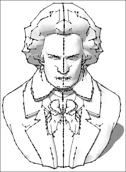
FIGURE 9-13: The line is far less objectionable when it’s well thought out.
Another good place to hide a cut is at a change in elevation, curvature, or color, as shown in Figure 9-14 . Placing a seam where the surface of a part is already interrupted or in transition will make it far less noticeable. This is the strategy most commonly employed for injection-molding parts. Pick up something around you that’s made of plastic and find the seams where the parts come together. If you can imitate that type of seam, people will readily accept that your object is a “real” thing. It will feel correct among manufactured things in our injection-molded world, and you’ll fool people into thinking your 3D printed part came from a factory somewhere.
FIGURE 9-14: Do the seams look out of place?
For very large constructions, the only option may be to establish a grid and cut into build-volume-size blocks. Sanding, finishing, and painting can work well on large parts, but expect to spend substantial time doing it right. If you’ve spent the energy to build something that big, it’s worth the extra time to make it amazing.
How to cut
Cutting a model into parts is very similar to using the Intersect Faces tool to combine groups (discussed earlier in the chapter). You use a piece of geometry as a cutter that will be intersected with the larger object and become the new edges of the cut.
If your model is fairly simple and you have SketchUp Pro, you can use the Solid Tools to short-circuit this process. Create a solid block as a cutting object and use the Solid Tools ⇒ Trim command. Remember to run CleanUp3and Solid Inspector2 on the new parts when you’re done. For more complex models, or users with SketchUp Make, use the Intersect Faces method:
1. Select the group you want to cut and make a new group around it.
The original group becomes a subgroup.
2. Working inside the new group, create geometry in the shape of the cut you want to make.
Work on top of the subgroup, so you place the cut correctly, as shown in Figure 9-15 .
3. When you’re done placing cuts, make the new geometry into its own group.
4. Select the Cutter object and choose Edit ⇒ Intersect Faces with Context (or choose Edit from the context-click menu).
Doing so draws a line at every place where groups touch. These new lines of intersection exist outside the subgroups and aren’t stuck to anything yet, as shown in Figure 9-16 .
5. Inside each group, use Explode to stick the intersection lines, cutting object, and base object together.
The surface of the cutting object becomes the sides of the new part.
6. Move back out to the master group and make as many copies of that group as the number of parts you’re dividing it into (see Figure 9-17 ).
7. In each copy, open the group for editing and erase everything you don't need in that part. Do the same in the other parts.
Just make sure you don’t erase what the object needs to do its job.
8. Run CleanUp3 on the new parts and use Solid Inspector2 to check for any accidental holes.
9. Position the parts back together to make sure everything lines up as expected, as shown in Figure 9-18 .
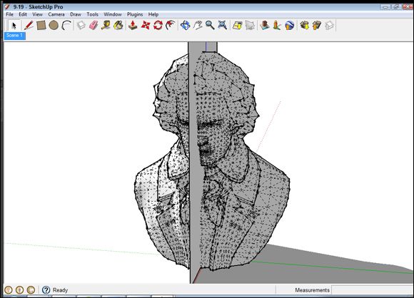
FIGURE 9-15: The cutter object can be a single plane; it’s going to become part of the solid object.
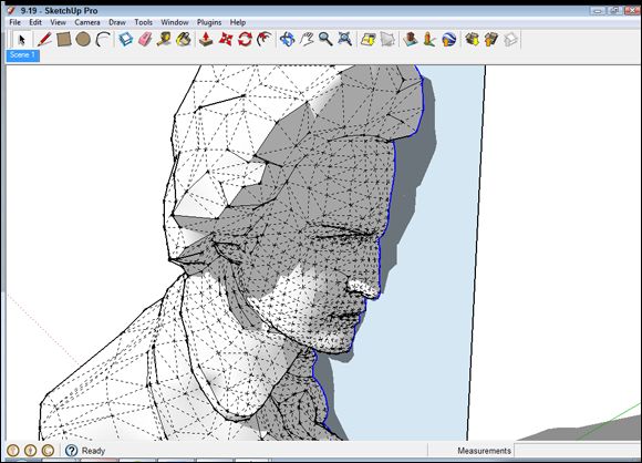
FIGURE 9-16: Lines of intersection created between the two groups.
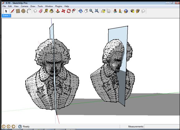
FIGURE 9-17: Make one copy of the group for each part of your model.
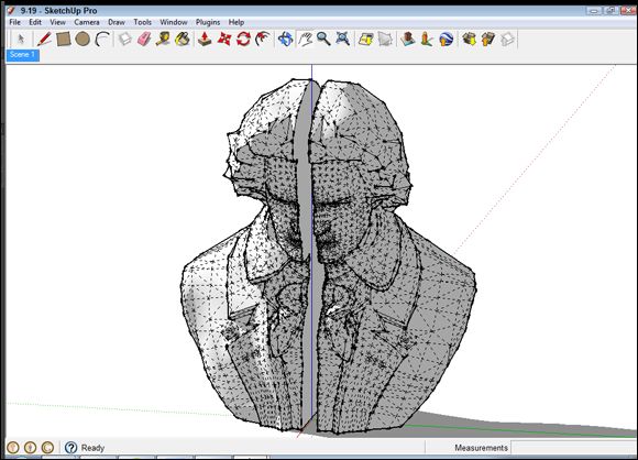
FIGURE 9-18: It still fits!
Exporting Your SketchUp File
After you’ve cleaned up your SketchUp model and you’re ready to print it, you have to get your 3D model out of SketchUp and into your 3D printer’s control software. Before your 3D printer can open your model, you have to export the model in either the STL or OBJ file format.
If you're using SketchUp Pro, you already have the option of exporting an OBJ file. To export an STL file from either version of SketchUp, you’ll need to install a free extension from the SketchUp Extension Warehouse called SketchUp STL. It’s a great tool created by the SketchUp team to make 3D printing easier.
Knowing Your 3D Printers
3D printers are available that print objects in materials ranging from plastic to titanium. The medical research world has even created machines that can build structures from human tissue. All that separates these technologies is cost. Affordable desktop 3D printers are limited to printing in plastics. So that 3D printer you bought for $500 can’t print you a new kidney. (Not yet, anyway, but don’t hold your breath.)
The two main ways 3D printers are compared to each other are in terms of cost per cm3 (that is, cost per cubic centimeter of printed object) and minimum layer height . Cost per cm3 is the cost of one cubic centimeter of printed volume; it’s typically the number used when comparing the cost of one 3D printing technology to that of another. Minimum layer height is the thickness of one layer in the object. The smaller the height between layers, the smoother the surface of the finished object will look and feel.
Desktop 3D printers
Desktop 3D printers are still an emerging technology. When starting out with your first desktop 3D printer, don’t expect it to work perfectly the first time out of the box. The machines haven’t reached that level of polish yet. It helps to see a 3D printer as a tool you’re learning to use, rather than as an appliance you just plug in. Before you dive into printing your own creations, spend some time going through the printer’s training materials. Print a few test objects and get a feel for using the machine.
Desktop 3D printers tend to be based on tried-and-true technologies that have been used in industrial machines for decades. The two technologies that are available now are fused deposition modeling and stereolithography. The following sections give you an overview.
Fused deposition modeling (FDM)
FDM printers represent the mostly widely available type of desktop 3D printer. They build objects using solid plastic fed through a fancy robotic glue gun-style nozzle. FDM printers are inexpensive to buy, with desktop models ranging from $500 to $2,500. FDM-printed parts are done the moment the printer is finished; no secondary process is needed to finish or strengthen the object. The parts that FDM printers make can be as strong as parts from injection molding, and cost around $0.04 per cm3 . On the downside, FDM 3D printers have limited maximum resolution and tend to have a lot of moving parts, which can impact their reliability.
FDM printers consume plastic filament as they build objects. Filament is drawn into the printer, heated, and then fused to form the object. Filament comes coiled on spools that look a bit like brightly colored weed-whacker wire. Spools are available inexpensively through vendors online and are starting to become available in large office supply stores.
Examples of FDM 3D printers are MakerBot Replicator ( www.makerbot.com ), Ultimaker ( www.ultimaker.com ), 3D Systems Cube ( http://cubify.com ), Affinia H-Series ( www.afinia.com ), and Solidoodle ( www.solidoodle.com).
Stereolithography
SLA 3D printers represent one of the oldest 3D printing technologies. They use a laser to build solid parts in a vat of liquid resin, selectively hardening the resin layer by layer. Desktop SLA machines cost between $2,500 and $8,000, but you’ll hear ongoing speculation about a printer emerging at a price below $1,000. Stereolithography offers superior printing resolution, which gives finished parts a glassy smooth surface. The machines are typically small and nearly silent, with a few moving parts. Prints from an SLA machine typically cost around $0.15 per cm3 and require some cleanup after printing. Also, due to the resin’s toxicity, printed objects must be washed in isopropyl alcohol before handling.
Stereolighography’s consumable resin is an amazing bit of chemical engineering. It’s a liquid at room temperature until it’s exposed to intense ultraviolet light, which hardens the resin into a solid plastic. Resin comes as a bottle of liquid; usually you have to buy it from the maker of your 3D printer to ensure compatibility. Resin has a set shelf life and needs to be stored with some care; it can begin to harden if left in sunlight.
Two examples of SLA machines are Formlabs Form 1 ( http://formlabs.com ) and B9 Creator ( http://b9creator.com ).
 As this book goes to press, DLP (digital light processing) printers are emerging on the desktop 3D printer market, with price points from $3,000 to $5,000 but likely to fall in the near future. The technology is similar to SLA, but uses less material.
Do-it-yourself and kit printers
Both FDM and SLA printers are available as kits and open-source DIY plans. In general, these 3D printers are good options for people who are interested in exploring printer technology and modifying their printers. Kits are cheaper than buying a printer, but often less reliable. The saying is, “If you build it yourself, you fix it yourself.”
Two examples of DIY and kit machines are RepRap ( http://reprap.org ) and Printrbot ( http://printrbot.com ).
Professional 3D printers
Professional 3D printers are typically housed in a dedicated department and operated by full-time employees. They are expensive, with prices in the hundreds of thousands of dollars, but offer capabilities beyond what is available in desktop models. As desktop 3D printing grows, and patents continue to expire, expect to see these technologies becoming cheaper and move into the desktop realm. Here’s the current lineup:
· Selective laser sintering (SLS): Selective laser sintering uses a laser to melt and fuse a finely powdered plastic. SLS machines can reproduce fine detail without adding any supporting structure to the model. (By and large, lasers that can manage these feats are still relatively expensive.)
· Inkjet, powder-based: Similar to SLS machines, these 3D printers use a powder that is selectively hardened by liquid glue sprayed from an inkjet printhead. The ink can be colored and mixed; this is one of the few technologies that can offer full-color 3D printing.
· Inkjet, resin-based: These machines are an expansion of stereolithography technology. They use an inkjet printhead to spray fine layers of a UV-sensitive resin, which is then hardened by a powerful UV light. Advertising materials for these printers talk about layer heights measured in atoms.
· Paper-based: These printers build objects out of copy paper by gluing the sheets together then cutting away the excess. The parts are immensely strong, and can be treated like wood after printing.
3D printing services
3D printing services offer access to professional-level machines on a pay-per-print basis. Cost is based on volume of material printed, and you receive your printed object by mail in a few working days. Each company offers detailed instructions on minimum part sizes, wall thicknesses, and feature size. Pay attention to these rules. The services know what their machines can do, and you don’t want to be stuck waiting a week for a part that didn’t come out right.
Two examples of 3D printing services are Shapeways ( www.shapeways.com ) and Ponoko ( www.ponoko.com ).
CAN I 3D PRINT IN METAL?
Yes, 3D printers that print in metal exist. But unless you live in a hollowed-out volcano and race fighter jets in your free time, you probably can’t afford to use them. Based on selective laser sintering (SLS) technology, these printers use an electron laser to fuse powdered metals in a hard vacuum. The parts they make are fantastically strong and complex, surpassing anything possible with traditional manufacturing technology. Current uses for SLS in manufacturing include custom medical implants, military jet engines, and spacecraft components. So if cost is no object, you can 3D print in metal.
If you need your 3D printed part made in metal, use a 3D printing service bureau or take a part printed with an FDM or SLA printer to a foundry. At the foundry, a process called a burnout makes a cast-metal version of the part.
Using Your 3D Printer
Your new 3D printer’s manufacturer will have documentation to help you learn how to use the printer and the software, so we don't go into detail on specific machines. The following sections touch on a few general concepts of 3D printing that are often not explained well. For a closer look at 3D printers, check out 3D Printing For Dummies by Kalani Kirk Hausman and Richard Horne.
Print early, print often
Desktop 3D printing is cheap. Really, unbelievably, remarkably cheap. Cost for running a typical desktop 3D printer is about 60 cents an hour. Once you’ve started the printer, it doesn't need any more input from you, which frees you to continue working on the design. With such an amazing tool that’s so cheap to use, don’t be afraid to print constantly. Print your SketchUp model over and over as you improve it; doing so develops it.
3D printers are built to print; they don’t like to stand idle. Print more often! You’ll become an old hand at using your machine, and get to see your design as it evolves in real time.
Test prints are great for catching errors and mistakes. Test prints are also a great way to document the evolution of a design. It’s a good idea to save a version of your SketchUp model that corresponds to each file you 3D print. If the print has an unexpected error, you can look back at that file and understand what went wrong, without having to dig too deeply into the version you have continued to work on. Keep some general points in mind:
· Test prints that use your 3D printer’s Low Quality setting will print faster, but with a rougher surface.
· Save test prints as the project goes on. They’re a great way to show progress, and clients love to see a physical expression of the work being done.
· Many 3D printing plastics are recyclable or biodegradable. When you're done with your models made of this stuff, toss them in the recycling bin or on the compost heap.
Inside your model
3D printed parts are unique in the world of fabrication. After you’ve created the outside of your part, you also get to decide what happens on its inside. Usually you let the 3D printer automatically handle the inside of the part, filling it with automatically generated structure. It’s also possible to model a part’s interior structure to change how it behaves. For example, you might want to hollow out the center of a part to make it lighter or add space for internal components. Some possible variations include
· Internal voids: On SLS and stereolithography machines, a common cost-saving strategy is to build parts as a thin shell with an empty interior. The resulting parts have compromised structural strength, but are printed using as little material as possible. Be sure to include drain holes so the un-hardened material you saved can escape from the part.
· Part density: FDM printers automatically generate a structure to fill the interior of their prints. The density of the structure is controlled by a setting called fill, which is stated as a percentage. Parts with 100% fill will be solid plastic all the way through, and are as strong as injection-molded parts. Typically, FDM printers default to building parts at 10% fill, meaning that 10 percent of the interior is filled with plastic. Higher fill percentage means more plastic used — and longer print times. Generally speaking, anything over 40 percent is a waste of time and plastic.
· Outer wall thickness: Another FDM printer setting, this deals with the amount of material put into the walls of the object before starting the Infill. Look for a setting called Shells, which is the number of layers of plastic the printer will use to make the outside of the model. If you're having trouble with parts crushing, increase the number of Shells; otherwise leave this setting alone.
· Flexibility: Flexible materials are available on most 3D printers, usually by using a special flexible plastic filament. You can also make structures flexible by making them very thin with 0 percent infill.
Going beyond Basic 3D Printing
The more you use your 3D printer, the more you may find it affecting your SketchUp designs. Don’t be surprised if your designs become a bit more ambitious and mechanically complex. This section of the chapter outlines some possible directions and factors to watch out for.
Designing parts that connect
So you cut your model into parts. Now you need a way to get it to all stay together after it’s printed. In this section, you discover different strategies and features, mechanical and otherwise, that you can build into your model for attaching its parts together.
Tolerance and clearance
Before we get into a discussion about mechanical connections, you need to understand two more of those pesky realities that crop up when you move out of SketchUp’s idealized environment: tolerance and clearance.
· Tolerance is the difference between the measurement of your part in SketchUp and the measurement of the part produced by your 3D printer. If you draw a 10mm cube in SketchUp and 3D print it, none of the measurements of the printed cube will be exactly 10mm. The differences are small — just a few tenths of a millimeter more or less — but they can cause problems if your 3D printed parts have to connect to parts that already exist in the real world. The 3D printer’s manufacturer provides a number for the machine’s tolerance as a plus or minus value, usually something like pm0.05mm. This is the maximum variation for that machine, and you should be aware of it as you work.
· Clearance is the extra space you need for parts to slide past one another. If you try to install a 10mm peg in a 10mm hole, you’re in for a bit of a surprise when the two won’t go together. The peg and hole can fit perfectly in SketchUp, but that’s not what’s going to happen in the real world where you have to contend with friction. The surface of the peg is so much like the surface of the hole that the friction between them will keep the peg from ever going in if the fit is too exact. You need to add a small amount of space called clearance so the two parts can slide past each other. How much clearance you use depends on how the part needs to move. A spinning shaft, for example, needs more clearance than a simple snap fitting.
You’ll come to an inherent understanding of clearance and tolerance as you do more designing in SketchUp for 3D printing. As you use your 3D printer, you’ll be able to find values that work well with your equipment.
As a starting point, add 0.2mm of clearance to all holes and 0.5mm of clearance to any points of rotation.
Glue
Glue, shown in Figure 9-19 , is the universal way to stick something to something else. Unfortunately, it’s also the weakest and most unreliable method. Glue joints in plastics have very little strength and will tend to break under stress, in response to temperature change, or if you look at them funny. If your part is meant to be anything more than a visual model, use one of the other attachment systems.
· The plastics used in 3D printers — ABS, PLA, PVA, nylon, and PETT — all require special glues to bond. These glues are available, but must be ordered from an online retailer.
· Biodegradable starch plastics such as PLA have a crystalline structure that doesn't work well with liquid superglue. The glue tends to stay liquid and migrate unexpectedly across the surface of the part.
· When in doubt, use epoxy. Its messy stuff, but will stick to pretty much anything.
· There are no glues that will stick to the flexible materials that are available for 3D printers. To attach parts made of that stuff, you’ll need to look into a process called thermal welding, which is way outside the scope of this book.
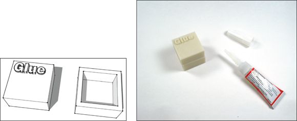
FIGURE 9-19: Works cosmetically, but don’t expect much durability unless you use epoxy.
Snap fittings
Snap fittings are an awesome way to take advantage of your 3D printer. Properly designed, they’ll let you pop your model together as soon as the parts come off the printer. Snap fittings can also be removable, so you can change out various parts of your model as the design evolves.
In SketchUp, you create snap fittings like those shown in Figure 9-20 by following two general steps:
1. Create the tongue with the Line and Push/Pull tools.
2. Create a matching capture point on the opposing part.
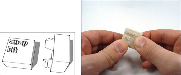
FIGURE 9-20: A snap fit joint is great for reusable connections.
As you create your snap fittings, keep these points in mind:
· Be sure to leave enough space for the tongue to bend backward as it slides into place.
· Include a clearance of between 0.2mm and 0.5mm, depending on how tight you need the joint to be.
· Always position snap fittings so they print horizontal to the 3D printer’s build platform. Snap fittings printed in the Z direction, perpendicular to the platform, tend to break off.
· If you want your snap fitting to be re-openable, make sure that you provide a way for the tongue to disengage from the capture. This can either be a ramp in the geometry that forces the tongue backward as you pull on the joint, or an access point that lets you release the tongue manually.
· Don’t make the tongue too thick. It has to bend for the joint to go together.
Press fit
A press fit is when two parts are designed with very little clearance between them. When the parts are forcibly pressed together, friction keeps the joint together with no additional hardware or glue.
To make a press fit like the one shown in Figure 9-21 , use the Offset tool to create an outer lip on one side of the connection and an inner lip on the other side. Include a clearance of 0.2mm or less between parts, so you can still assemble them. Keep a few points in mind about press fits:
· For a press fit to work well, it needs to be a tight connection. You might need a small hammer, large clamp, or your whole body weight to press the parts together.
· A press fit is usually a one-way connection. After you put it together, don’t expect to ever get it back apart.
· Press fits don’t scale up well. Always design them at the size at which they’ll be printed.
· The tight clearance of a press fit can make it difficult to get started. Running a hobby knife or deburring tool around the edge of the hole will widen that area a bit and help you get the parts together.
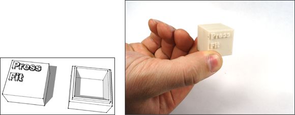
FIGURE 9-21: A press fit is an easy connection to draw in SketchUp.
Bolts, screws, and hardware
The strongest connection you can make between 3D printed parts is one held together with metal hardware. These connections are great for things that are more than just prototypes — for example, parts for robots or mechanisms.
When integrating hardware into your design, include the hardware in your SketchUp model. Take measurements of the parts you’re planning to use and model them in SketchUp. After you make these components, save them to the component library so that you can use them again with one click. Keep these points in mind:
· Remember to include enough clearance in your holes for the hardware to be installed.
· If you’re using bolts or screws and don’t want to include a matching nut, a trick is to slightly undersize the holes. The threads of the bolt will cut into the excess plastic and hold it firmly in place, as shown in Figure 9-22 .
· Online hardware suppliers like McMaster Carr and Amazon Supply stock every fastener known to the human race. If your local hardware store doesn't have what you're looking for, these online stores will have it.
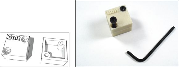
FIGURE 9-22: Nothing says strength like an exposed bolt.
Testing your model’s moving parts
Whatever connection system you are using, always test it first. Before you start printing a giant project, build a small version of the attachment. It only takes a few minutes to design and 3D print, and will give you a chance to make sure the joint works properly. Nothing is worse than modeling a system of joints and then discovering they don't fit together properly.
Designing Things That Move
3D printing something you’ve designed in SketchUp is cool. 3D printing something that moves is even cooler. This section focuses on a few features you can include to make your creations more than just interestingly shaped hunks of immobile plastic.
Captive joints
A captive joint is a moveable connection that comes out of your 3D printer already assembled and working. Captive joints tend to be mechanically simple hinges, ball joints, and chain links. Their simplicity is their power. A 3D printer can quickly build objects with hundreds of captive joints that would take days to construct by hand. Poseable action figures, clothing, and the chainmail in Figure 9-23 are examples of simple captive joints assembled into complex structures.
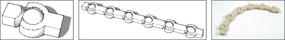
FIGURE 9-23: Captive joints bring the power of multiplication to life.
Creating a captive joint requires trial and error. You’ll have to experiment to get the right combination of clearances and shapes. Keep these principles in mind while you work on captive joints:
· Use components when building structures with captive joints; they let you automatically modify all the joints at once as you work.
· How you design captive joints depends on the specific 3D printing technology you’re using. SLS-based 3D printers can build captive joints that are a few millimeters across. FDM printers can make fantastically strong joints, but the printed objects need to be much bigger.
· A structure is only as strong as its weakest part. Don’t make a joint so fine that it falls apart in your hands.
· Test print parts of your structure as you work. Remember, 3D printing is cheap, and with captive joints, you're pushing the limits of the technology. Test objects will help you check your work and keep your sanity.
Pins
Pins are small, round snap fittings that are pressed into place to make a connection. They can be a versatile replacement for hardware. In Figure 9-24 , a single pin acts as a point of rotation, and two or more will hold parts firmly together.
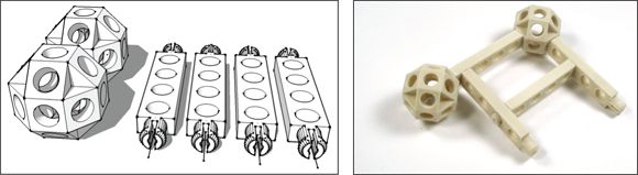
FIGURE 9-24: A system of pin joints used to make a simple toy.
Pins are like bolts, except you get to make them in exactly the size and shape you need. You can also print more when you run out.
· When designing your pins, give them one flat side. The flat side gives you a way to build the pins without using support material — while keeping the tongues horizontal to the build platform. This process also keeps finished pins from rolling off your desk.
· Make your pins into components so you can easily modify all of them at once if you need to.
· When designing a project with pin joints, make an effort to standardize around a small number of pin sizes. Standardization helps keep things tidy and simplifies assembly.
Gears
Gears are great for creating complex motions or transferring movement through a mechanism. That is probably the most understated description of the deepest rabbit hole of the industrial age. Gears are in every mechanical device you can imagine. They have existed in some form or other since before recorded history, and are the basis for an incalculable number of clever devices that make everyday life possible.
Making gears is fun and inspires lots of folks to start experimenting with 3D printing. Figure 9-25 shows a simple gear system that can become so much more. To help you get started, here a few basic principles for making gears:
· Gears need to have clearance between their surfaces to work properly. Gears that are too perfect a fit will bind up. Include a clearance at both the point of rotation and between the teeth of the gear and the teeth of its mate.
· A SketchUp extension called Involute Gears automates the process of making gears. The extension’s creator hasn’t made it available in the SketchUp Extension Warehouse, so you’ll need to locate it by searching sketchup gear plugin through Google.
· Creating optimized gears from scratch is a technical art form that has fallen out of practice. If you want to learn more about designing gears, I recommend getting a copy of Machinery’s Handbook (Industrial Press). After almost a century in print, this book is the gold standard for anything gear-related.
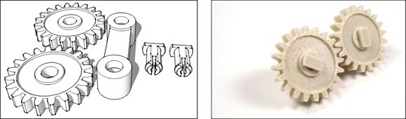
FIGURE 9-25: Welcome to the New Industrial Revolution. Time to gear up.
All materials on the site are licensed Creative Commons Attribution-Sharealike 3.0 Unported CC BY-SA 3.0 & GNU Free Documentation License (GFDL)
If you are the copyright holder of any material contained on our site and intend to remove it, please contact our site administrator for approval.
© 2016-2026 All site design rights belong to S.Y.A.