CCNP Security FIREWALL 642-618 Official Cert Guide (2012)
Chapter 12. Using Transparent Firewall Mode
This chapter covers the following topics:
• Firewall Mode Overview: This section provides an overview of the two firewall modes that an ASA can use.
• Configuring Transparent Firewall Mode: This section covers the configuration steps necessary to use transparent firewall mode.
• Controlling Traffic in Transparent Firewall Mode: This section explains how to use access lists to control the movement of traffic when an ASA is configured for transparent firewall mode.
• Using ARP Inspection: This section covers the feature that can be used to inspect ARP replies to prevent ARP spoofing attacks.
• Disabling MAC Address Learning: This section discusses how to disable MAC address learning to prevent MAC address spoofing attacks that can confuse or overwhelm an ASA in transparent firewall mode.
The Cisco Adaptive Security Appliance (ASA) can operate in one of two firewall modes. This chapter explains the concepts behind routed firewall mode, operating at Layer 3, and transparent mode, operating at Layer 2. In addition, this chapter covers how to configure and use transparent mode and how to prevent some attacks on it.
“Do I Know This Already?” Quiz
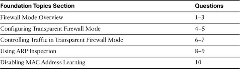
The “Do I Know This Already?” quiz allows you to assess whether you should read this entire chapter thoroughly or jump to the “Exam Preparation Tasks” section. If you are in doubt about your answers to these questions or your own assessment of your knowledge of the topics, read the entire chapter. Table 12-1 lists the major headings in this chapter and their corresponding “Do I Know This Already?” quiz questions. You can find the answers in Appendix A, “Answers to the ‘Do I Know This Already?’ Quizzes.”
Table 12-1. “Do I Know This Already?” Section-to-Question Mapping
Caution
The goal of self-assessment is to gauge your mastery of the topics in this chapter. If you do not know the answer to a question or are only partially sure of the answer, you should mark that question as wrong for purposes of the self-assessment. Giving yourself credit for an answer you correctly guess skews your self-assessment results and might provide you with a false sense of security.
1. When an ASA begins to operate in transparent firewall mode, what information does it use to forward packets?
a. Source IP addresses.
b. Destination IP addresses.
c. Source MAC addresses.
d. Destination MAC addresses.
e. All of the answers are correct.
2. When an ASA is operating in transparent firewall mode, how many interfaces can be active in a bridge group?
a. 1
b. 2
c. 3
d. As many as the license key supports
e. As many as are installed
3. Which of the following are valid applications for an ASA operating in transparent firewall mode? (Choose all that apply.)
a. When only IP packets need to be inspected
b. When non-IP packets need to be inspected
c. A network where IP addressing cannot be reworked to support a firewall
d. A network that can be segmented into new IP subnets on each side of a firewall
4. When the firewall transparent command is entered, what happens first?
a. The ASA reboots.
b. The ASA begins bridging traffic with the current configuration.
c. All interface IP addresses are cleared.
d. The running configuration is cleared.
5. How many IP addresses can you configure on an ASA and its interfaces in a bridge group when transparent firewall mode is active?
a. 1
b. 2
c. 3
d. One per interface
6. Which of the following are correct statements about the default behavior of transparent firewall mode as it controls packet movement? (Choose all that apply.)
a. ARP packets are forwarded.
b. Broadcast packets are not forwarded.
c. Multicast packets are forwarded.
d. Non-IP packets are not forwarded.
7. Which one of the following commands should be used to permit Spanning Tree Protocol packets to pass through an ASA in transparent firewall mode? Assume that the access list will be applied to the ASA interfaces.
a. access-list STP extended permit stp any any
b. access-list STP ethertype permit bpdu
c. access-list STP broadcast permit bpdu any
d. access-list STP extended permit bpdu
8. Which of the following are valid reasons to use ARP inspection? (Choose all that apply.)
a. To prevent ARP packets from being exchanged with the outside network
b. To prevent spoofed ARP packets in a man-in-the-middle attack
c. To make sure that ARP packets are adhering to the ARP protocol standard
d. To prevent a denial-of-service attack on the ASA’s MAC address table
9. Once ARP inspection is enabled, which one of the following describes the additional information that is needed for ARP to function properly across an ASA in transparent firewall mode?
a. Nothing; ARP inspection is self-sufficient.
b. The IP addresses of any ARP servers in the network.
c. Static ARP entries for all trusted hosts.
d. An access list to permit ARP packets on all ASA interfaces.
10. By default, what information does an ASA learn and maintain in its MAC address table?
a. Source MAC address, ingress interface
b. Destination MAC address, ingress interface
c. Source MAC address, egress interface
d. Destination MAC address, egress interface
Foundation Topics
Beneath all the security features and processes an ASA offers, it must forward traffic from one interface to another. An ASA can operate in either routed firewall mode, similar to a router, or in transparent firewall mode, much like a transparent bridge.
You can configure an ASA for either firewall mode, depending on the security requirements and the network topology. This chapter discusses the two modes in detail and how you can leverage them appropriately in practice.
Firewall Mode Overview
By default, an ASA operates by performing all of its operations at OSI Layer 3 using IP packets and IP addresses. All the traffic inspection and forwarding decisions are based on Layer 3 (IP address) parameters, although the ASA can look at higher layers within the IP packets being examined. The ASA itself maintains IP addresses on its own interfaces and acts as a router or gateway to the networks that connect to it. This is known as the routed firewall mode.
As with a router, each ASA interface must be connected to a different IP subnet and be assigned an IP address on that subnet. This arrangement is shown in Figure 12-1, where the inside interface sits on IP subnet 192.168.200.0/24 and the outside interface sits on 192.168.100.0/24. Management traffic can be permitted on either interface, or the ASA can have a dedicated management interface on yet another subnet.
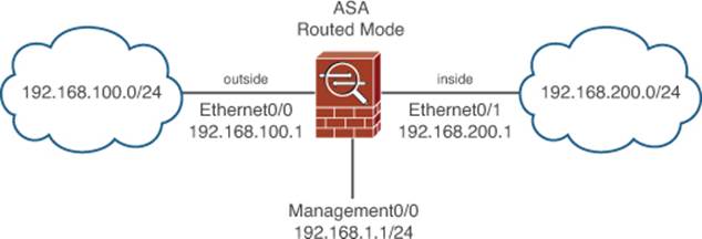
Figure 12-1. Example of an ASA in Routed Firewall Mode
In routed firewall mode, an ASA bases its packet forwarding decisions on the destination IP address. It can use static routes or participate in dynamic IP routing with other neighboring routers.
When an ASA in routed firewall mode is installed or inserted into a network for the first time, the network must become segmented across the ASA’s interfaces. For example, where a single IP subnet used to be, the inside and outside interfaces now form the boundary of two separate subnets.
This can make the installation difficult, as some readdressing must take place. The easiest approach is to keep the original IP addressing on the ASA’s inside interface, where the majority of protected hosts reside. The outside interface can take on an address from a new subnet that is shared between the ASA and the next-hop router. In other words, the outside of the ASA usually has fewer directly connected hosts to readdress to a new subnet.

An ASA can also be configured to operate in transparent firewall mode, such that it appears to operate as a Layer 2 device, without becoming a router hop or a gateway to its connected networks. This is also known as a Layer 2 firewall or a stealth firewall, because the ASA’s interfaces have no assigned IP addresses and cannot be detected or manipulated. Only a single management address is used for traffic sourced by the transparent firewall itself or destined for a management session.
As a Layer 2 device, an ASA in transparent firewall mode can be installed or wedged into an existing network, separating the inside and outside without changing any existing IP addresses. In Figure 12-2, notice how the ASA running in transparent firewall mode has its inside and outside interfaces connected to the same IP subnet. This is commonly called a “bump-in-the-wire” because the ASA doesn’t break or segment the IP subnet along a wire but instead more or less becomes part of the wire. This makes a new installation straightforward.
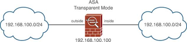
Figure 12-2. Example of an ASA in Transparent Firewall Mode
You can think of a transparent mode firewall as a type of transparent bridge, where packets are bridged from one interface to another based only on their MAC addresses. The ASA must maintain a MAC address table of the source address learned in each received packet, along with the interface on which the packet arrived. Once a MAC address has been learned, the ASA is able to forward a packet to that address by knowing the location or the egress interface where that same address has been active before.
What if a MAC address is not found in the table? A transparent bridge would flood the original packet out the other interface automatically, assuming that the MAC address must be out there somewhere. The ASA cannot do that simply because it has to maintain security policies that might limit where a packet should go. Instead, an ASA will attempt to discover a destination MAC address by probing for its existence in one of the following ways:
• ARP request: When the destination IP address is located on a local subnet that is directly connected to the ASA, the ASA will send an ARP request to force the destination to answer with its own MAC address in an ARP reply. Once the reply is received, the ASA has learned the location of the MAC address.
• Ping request: When the destination IP address is located on some distant subnet, the ASA will send an ICMP echo request (ping) to the destination. When the destination host or a router responds, the ASA can learn the location of the next-hop router’s MAC address that can be used to reach the destination.
In transparent firewall mode on ASAs running software release 8.4(1) or later, the ASA interfaces can be mapped into one or more logical bridge groups. Each bridge group functions as an independent transparent firewall; traffic passing through one bridge group cannot reach any other bridge group internally. If traffic must be passed from one bridge group to another, an external router must be used. Up to eight bridge groups are supported on a physical ASA platform, with 2–4 interfaces assigned to each. At a minimum, a bridge group must contain two interfaces—usually named the inside and outside.
You can leverage multiple bridge groups to create several independent transparent firewalls, as opposed to using multiple security context mode. Figure 12-3 shows an ASA that has been configured with two bridge groups. Although the bridge groups are isolated from each other, be aware that firewall-management functions, such as syslog and AAA server configurations, are shared across all the bridge groups configured on a single ASA.
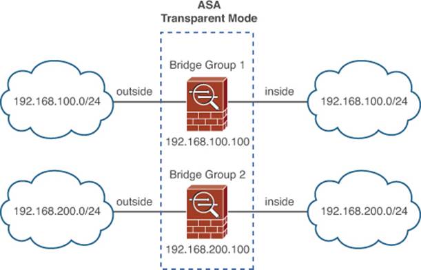
Figure 12-3. Example of Two Bridge Groups in Transparent Firewall Mode
Software releases prior to 8.4.1 support one inherent bridge group. Only two interfaces are supported: the inside and the outside. You can assign the inside and outside names to two interfaces arbitrarily. Once those interfaces are configured, the ASA will not permit a third interface to be configured. The only exception is the management-only interface, which you can configure and use to reach the ASA for administration purposes.
In multiple context mode, each context can support one or more bridge groups. Each context must use a set of interfaces that is different than the set used by any other context. In other words, contexts cannot share inside and outside interfaces due to the bridging operation. Security contexts are covered in detail in Chapter 13, “Creating Virtual Firewalls on the ASA.”
In transparent firewall mode, all of the interfaces in a bridge group must share the same IP subnet; however, IP packets are still inspected without the Layer 2 limitation. Full extended access lists (IP protocol and port numbers) are used to evaluate traffic policies, and the ASA’s application inspection engines are able to interpret IP activity at any layer. As of release 8.0(2), an ASA can integrate Network Address Translation (NAT) with transparent firewall mode.
In routed firewall mode, an ASA can inspect and forward only IP packets. Transparent firewall mode doesn’t share that same limitation because it focuses on Layer 2 and MAC addresses and is able to handle non-IP packets as well. Non-IP packets can be permitted by configuring a special interface access list that contains specific EtherType values.
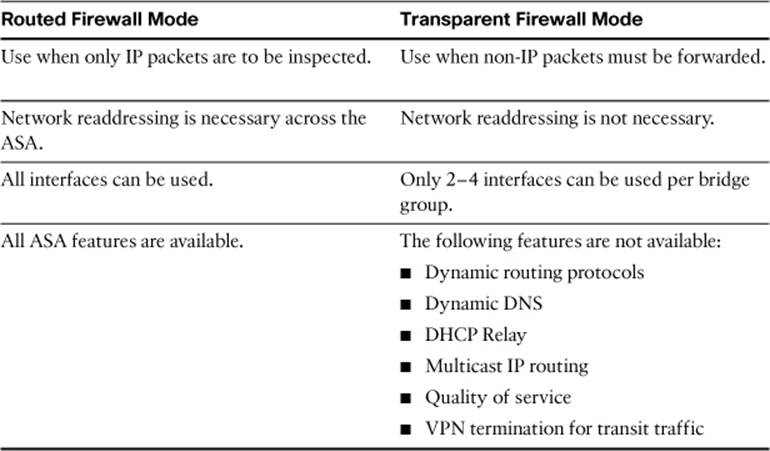
Before you choose either routed or transparent firewall mode, you should be aware of the strengths and weaknesses of each mode. Table 12-2 provides a summary of the mode characteristics.
Table 12-2. Comparison of the Routed and Transparent Firewall Modes
Configuring Transparent Firewall Mode
Before you begin configuring transparent firewall mode, you should verify which mode is currently in use. You can do that with the show firewall EXEC command. In Example 12-1, the ASA is running in the default routed (or “router”) mode.
Example 12-1. Verifying the Current Firewall Mode
ciscoasa# show firewall
Firewall mode: Router
ciscoasa#
You can enable transparent firewall mode with the following command:
ciscoasa(config)# firewall transparent
Transparent firewall mode begins immediately and doesn’t require a reload; however, because transparent and routed firewall modes use different approaches to network security, the running configuration will be cleared as soon as transparent firewall mode begins. The idea is to enter transparent firewall mode and build an appropriate configuration from scratch.
For that reason, you should save the routed firewall mode running configuration to flash memory or to an external server before enabling transparent firewall mode. That way, you will have a copy of the configuration in case you need to revert to routed firewall mode or refer to some portion of that configuration. Because the configuration is cleared, ASDM does not offer any way to change the firewall mode.
Next, you will need to set aside ASA interfaces and configure them for transparent firewall use. For ASA release 8.4(1) or later, you can configure up to four interfaces as part of a bridge group. With earlier releases, you must use exactly two interfaces—one interface will face the “outside,” less secure part of the network, while the other will face the “inside,” more secure area.
Configure the interfaces exactly as you would with routed firewall mode, with the exception of any IP addresses, by supplying the following parameters:
• Interface speed and duplex mode
• Interface name
• Security level
• Bridge group number (ASA release 8.4(1) and later)
In ASDM, navigate to Configuration > Device Setup > Interfaces, select an interface, and click Edit. You can enter the interface parameters as shown in Figure 12-4. Be sure to configure the same bridge group number on all interfaces that will become part of the same bridge group.
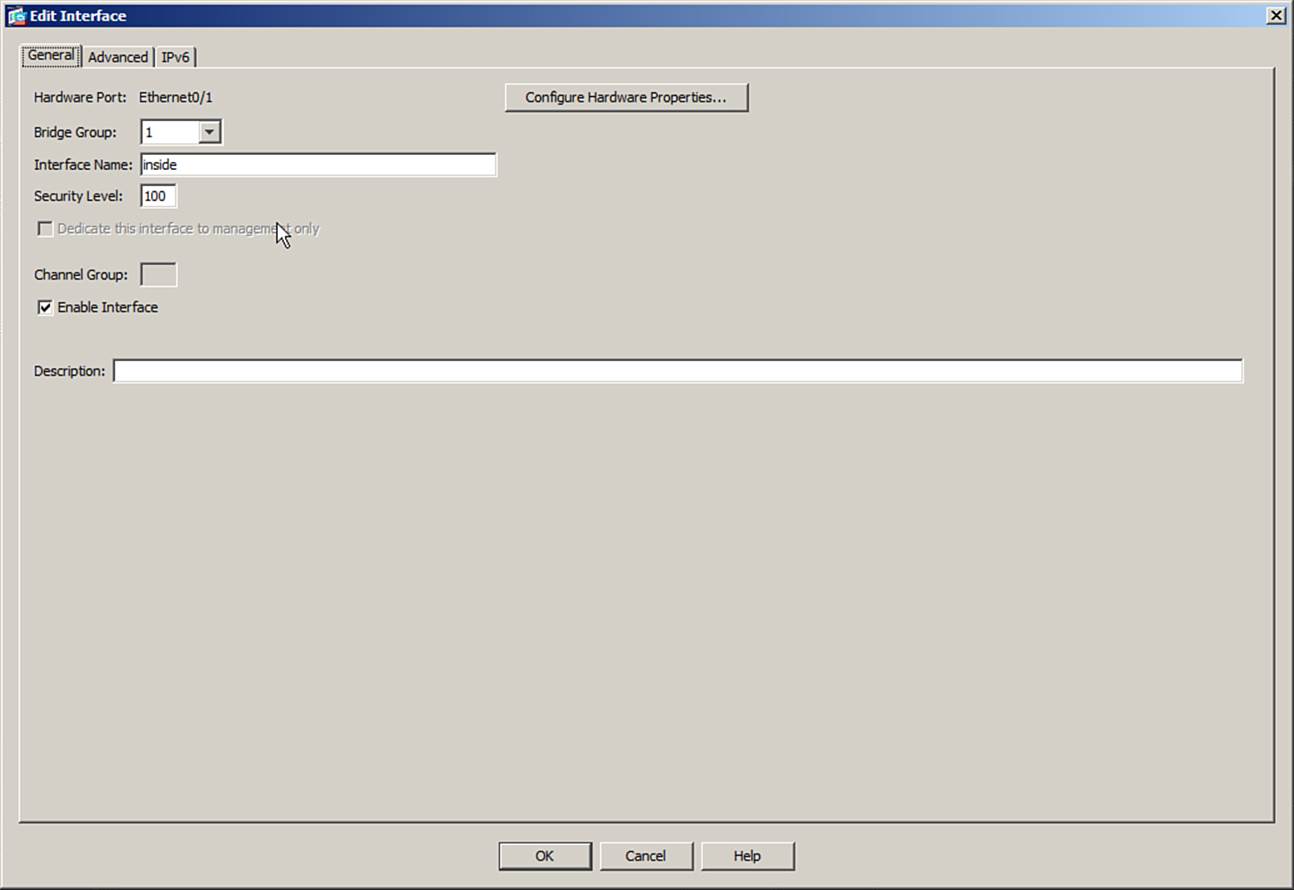
Figure 12-4. Configuring a Transparent Firewall Interface
If you choose to configure interfaces with the CLI instead, you can use the nameif, security-level, and bridge-group interface configuration commands. As an example, suppose the Ethernet0/0 interface will face the outside, while Ethernet0/1 will face the inside. Both interfaces will be part of bridge group 1. You could use the commands listed in Example 12-2 to configure the two interfaces.
Example 12-2. Configuring Interfaces in Transparent Firewall Mode
CISCOASA(config)# interface ethernet0/0
CISCOASA(config-if)# nameif outside
CISCOASA(config-if)# security-level 0
CISCOASA(config-if)# bridge-group 1
CISCOASA(config-if)# no shutdown
CISCOASA(config-if)# exit
CISCOASA(config)# interface ethernet0/1
CISCOASA(config-if)# nameif inside
CISCOASA(config-if)# security-level 100
CISCOASA(config-if)# bridge-group 1
CISCOASA(config-if)# no shutdown
CISCOASA(config-if)# exit
Next, assign a single IP address to each bridge group as a whole. This address will be used for management traffic, such as Telnet, SSH, HTTP, SNMP, syslog, TFTP, FTP, and so on. If you configure the ASA for multiple context mode, you should configure one IP address for each bridge group on each security context, including the admin context. From the interface list in ASDM, select Add and choose Bridge Virtual Interface (BVI). Configure the bridge group number and IP address, as shown in Figure 12-5.
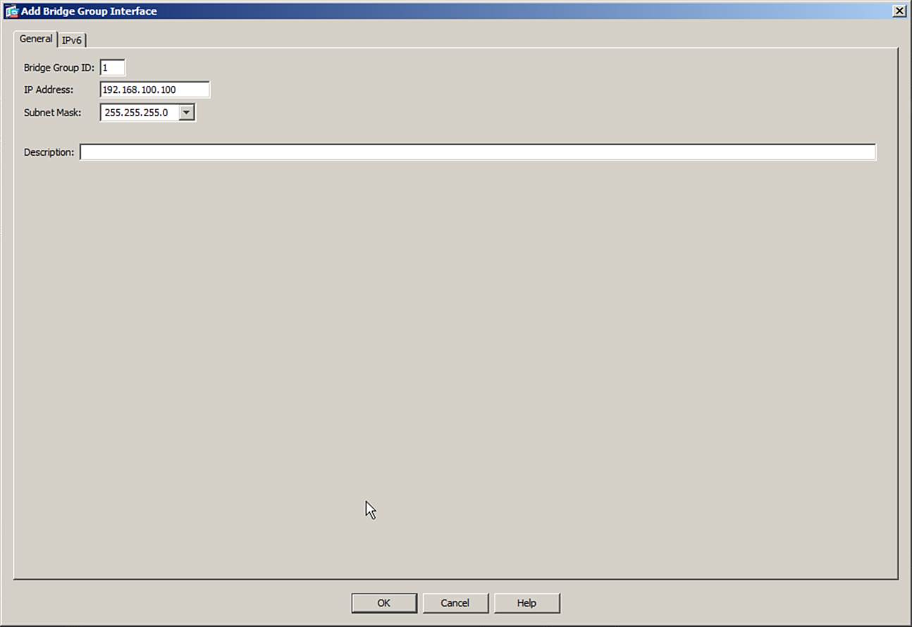
Figure 12-5. Configuring a BVI with an IP Address
From the CLI, you can use the following command to configure an IP address for a bridge group:
CISCOASA(config)# interface BVInumber
ciscoasa(config-if)# ip address ip-address subnet-mask
Before the ASA can communicate with any host that is located outside the local subnet, it will need additional routing information. Dynamic routing protocols are not supported in transparent firewall mode. However, you can configure one or more static routes instead; enter the following command for each one:
ciscoasa(config)# route interface network mask gateway [metric]
The remote IP network and subnet mask can be found on the named interface using the next-hop gateway router address. You can also specify a distance metric, which is the number of router hops until the gateway is reached. If you omit the metric, it defaults to one hop.
Figure 12-6 shows a scenario where an ASA in transparent firewall mode is configured with bridge group 1 using IP address 192.168.100.100. The ASA must be able to communicate with hosts on the 192.168.200.0/24 and 192.168.201.0/24 networks, which are located behind a router at 192.168.100.5. The ASA also needs a default route that points to a router on the outside interface at 192.168.100.1. The commands listed in Example 12-3 can be used to configure the necessary static routes.
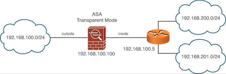
Figure 12-6. Example Scenario Requiring Static Routes
Example 12-3. Commands Used to Configure Static Routes for Figure 12-6
ciscoasa(config)# route inside 192.168.200.0 255.255.255.0 192.168.100.5
ciscoasa(config)# route inside 192.168.201.0 255.255.255.0 192.168.100.5
ciscoasa(config)# route outside 0.0.0.0 0.0.0.0 192.168.100.1
You should also configure static routes for any NAT entries that involve IP addresses that are not located on the local network. As well, static routes are necessary for voice traffic inspection when the endpoints are located more than one router hop away.
Controlling Traffic in Transparent Firewall Mode
An ASA can enforce its security policies in transparent firewall mode just as it does in routed firewall mode. For instance, unicast IP packets are permitted to flow from an interface configured with a higher security level to one with a lower security level interface, while explicit access list rules must be used to permit packets to flow from lower to higher security levels. IP packets are also subject to the ASA’s traffic inspection engines and MPF configuration.
However, transparent firewall mode differs from routed firewall mode in several ways:

• ARP packets are permitted to pass in both directions without any explicit ACL rules. You can configure ARP inspection, covered in the section, “Using ARP Inspection,” to control their movement.
• Broadcast and multicast packets are not permitted by default; explicit ACL rules are required.
• Routed non-IP traffic can be permitted by using EtherType ACLs.
If you plan to allow specific broadcast- or multicast-based protocols to pass through a transparent firewall mode ASA, you will need to configure an ACL that permits the packets. The ACL should be applied to an ASA interface in the inbound direction, to permit the packets to flow into the ASA and be forwarded out the other side. For protocols that are bidirectional, you can configure and apply an ACL inbound on both ASA interfaces.
Because broadcast and multicast traffic are not subject to the normal application inspection processes, you should configure the ACLs to be as specific as possible. Be sure to identify the protocol, any destination port number, and the destination address used in the inbound packets. Broadcast packets can use the all-networks 255.255.255.255 address or a subnet broadcast address as the destination. Multicast packets must be identified by the multicast group address as the destination.
As an example, suppose an ASA in transparent firewall mode separates the two routers shown in Figure 12-7. The routers exchange routing information with Open Shortest Path First (OSPF) protocol, which uses IP protocol 89 with destination addresses 224.0.0.5 and 224.0.0.6. You can use the commands listed in Example 12-4 or their equivalent in ASDM to permit the OSPF packets to pass through the ASA.
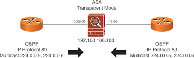
Figure 12-7. IDS and IPS Operational Differences
Example 12-4. Commands to Configure the Access Lists for Figure 12-7
ciscoasa(config)# access-list EXTRA-TRAFFIC extended permit ospf any host 224.0.0.5
ciscoasa(config)# access-list EXTRA-TRAFFIC extended permit ospf any host 224.0.0.6
ciscoasa(config)# access-group EXTRA-TRAFFIC in interface outside
ciscoasa(config)# access-group EXTRA-TRAFFIC in interface inside
By default, only IP packets are allowed to pass through an ASA, provided that the packets are permitted by the various inspection processes. If you need to pass non-IP traffic through an ASA, you can create a special EtherType access list that permits only packets with specific EtherType values.
To add a new EtherType rule in ASDM, navigate to Configuration > Firewall > Ethertype Rules, then select Add. Identify the interface where the access list will be applied, along with the action (Permit or Deny), the EtherType value, and an optional description. You can enter the EtherType value as a hex number or select from a pull-down list of values. You can keep adding more EtherType rules as needed.
As an example, suppose you want to permit IEEE 802.1d Spanning Tree BPDU packets, as well as TRILL packets (EtherType 0x22F3). Figure 12-8 shows the resulting EtherType rule list. Notice that the same two rule entries have been created and applied to the inside and outside interfaces.
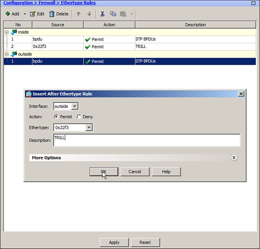
Figure 12-8. Configuring an EtherType Access List in ASDM
In the CLI, use the following command to create an entry in an EtherType ACL. You can repeat the command to define more entries.
ciscoasa(config)# access-list acl_id ethertype {permit | deny} {any | bpdu | ipx |
mpls-unicast | mpls-multicast | ethertype}
The ethertype value can be a 16-bit hex number greater than 0x600, or one of the following keywords:
• any: Any non-IP packet
• bpdu: Bridge protocol data units used for Spanning Tree Protocol operation
• ipx: Novell IPX
• mpls-unicast: MPLS unicast
• mpls-multicast: MPLS multicast
Example 12-5 lists the commands necessary to permit IEEE 802.1d Spanning Tree BPDU packets, as well as TRILL packets (EtherType 0x22F3). After you have configured the EtherType ACL, you must apply it to both interfaces in the inbound direction using the access-group command.
Example 12-5. Configuring an EtherType Access List for Non-IP Traffic
ciscoasa(config)# access-list MY-ETHERTYPES ethertype permit bpdu
ciscoasa(config)# access-list MY-ETHERTYPES ethertype permit 0x22f3
ciscoasa(config)# access-group MY-ETHERTYPES in interface outside
ciscoasa(config)# access-group MY-ETHERTYPES in interface inside
What if you need to permit some broadcast traffic and some non-IP traffic? You can apply one EtherType access list and one extended IP access list to the same interface.
Using ARP Inspection
Hosts on a network use the Address Resolution Protocol (ARP) to correlate IP addresses with MAC addresses. When a host needs to send a packet, it knows the destination’s IP address but not necessarily the destination’s MAC address. The host can send an ARP request packet that is broadcast to all nodes on the local network to ask for the MAC address of a given IP address. If a node using that IP address exists, it can send an ARP reply packet to identify itself by its MAC address.
By default, an ASA in transparent firewall mode forwards all ARP packets it receives on one interface out the other interface. This means that protected hosts on the inside ASA interface will exchange ARP packets with unprotected hosts on the outside interface. Normally, that isn’t a problem, as long as the unprotected hosts use ARP appropriately.
A malicious host, however, can abuse ARP to leverage a man-in-the-middle attack. Figure 12-9 shows how this is possible. Host 192.168.100.222 on the inside of the ASA is configured to use 192.168.100.1 as its default gateway. That address exists on the outside router. When the inside host needs to communicate with a destination that is outside its local 192.168.100.0/24 subnet, it must send those packets to the gateway, which will relay the packets on toward their destination. The inside host does this by sending the packets to the gateway router’s MAC address. If the MAC address isn’t already known, the inside host must send an ARP request to ask for the MAC address that goes with IP address 192.168.100.1.
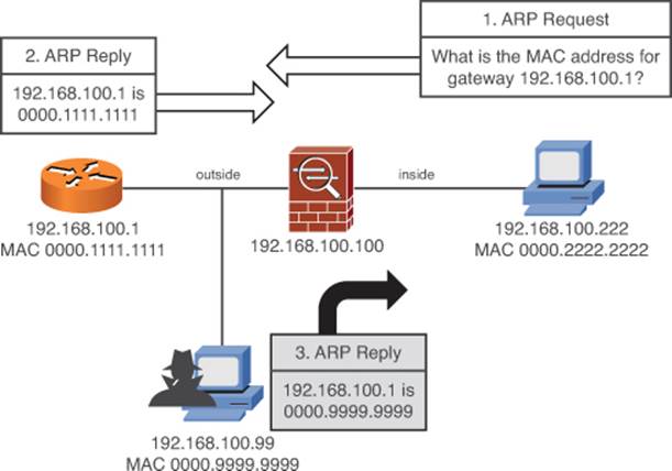
Figure 12-9. ARP Spoofing Attack with an ASA in Transparent Firewall Mode
The ASA will forward the ARP request to the outside, where it reaches the router. The router will answer with an ARP reply that contains its own IP and MAC addresses. So far, so good—after the ASA forwards the ARP reply back on its inside interface, the host will learn the router’s MAC address.
Now, suppose that a malicious host exists on the unprotected outside part of the network and would like to insert itself in the middle of the inside host’s conversations so that it can intercept and examine the traffic. When the ARP request packet is forwarded to the outside, the malicious host also receives it and sends its own spoofed ARP reply. The reply announces that IP address 192.168.100.1 (the gateway router) can be found at MAC address 0000.9999.9999 (the malicious host).
When the inside host receives this ARP reply, it will replace any other ARP entry for 192.168.100.1 with the MAC address of the malicious host. From now on, the inside host will send all of its outbound packets to the malicious host’s MAC address, unaware that the packets are now being intercepted, as shown in Figure 12-10.
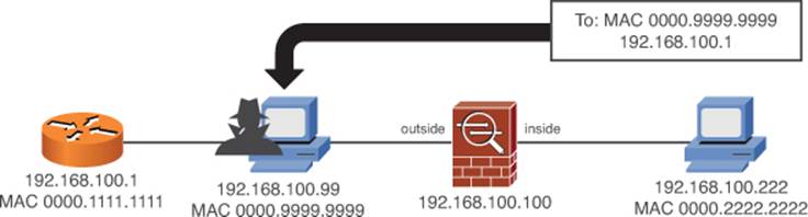
Figure 12-10. Man-in-the-Middle Attack Using Spoofed ARP Packets
The malicious host might also decide to send spoofed ARP replies that announce itself as the inside host too. If that happens, it can intercept all packets going to or coming from the inside host. This is known as a man-in-the-middle attack, which can be accomplished with exploit tools that are freely and readily available for downloading.
A transparent firewall can also maintain an ARP table, where MAC and IP addresses are associated as a pair. These are learned from ARP replies that are overheard on an interface. Normally, the ARP table is used only for management traffic to and from the transparent firewall, when the firewall itself needs to send packets to a destination.
To detect and prevent ARP spoofing, you can configure the ASA to support ARP inspection. ARP inspection uses static ARP entries as the basis for its inspection process. The ASA will examine each ARP reply packet it overhears and compare the source IP and MAC addresses, as well as the source interface, to known static entries in its own ARP table.
If the ARP reply matches an existing entry, the ASA forwards it out the other interface. If any of the ARP information conflicts with an existing entry, the ASA will assume the ARP reply contains spoofed addresses and will drop the packet. If an existing ARP entry can’t be found, the ASA can be configured to transmit or drop the ARP reply packet.
ARP inspection is only effective in handling ARP packets that need to traverse the ASA. In other words, the ARP requester and responder are located on different ASA interfaces. If both hosts are located on the same interface, the ARP reply can be answered directly without having to pass through the ASA.
To configure ARP inspection, begin by defining static ARP entries for all of the known hosts. Each entry will associate an IP address with a MAC address (dotted triplet nnnn.nnnn.nnnn format). These addresses are expected to be found on the specified ASA interface. Static ARP entries never age out.
In ASDM, navigate to Configuration > Device Management > Advanced > ARP > ARP Static Table. Click the Add button, and then select the interface and enter an IP and MAC address pair, as shown in Figure 12-11. The Proxy ARP check box is meant for routed firewall mode and does not apply to transparent firewall mode.
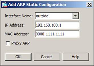
Figure 12-11. Configuring a Static ARP Entry for ARP Inspection
Next, select ARP Inspection. Select an ASA interface, click the Edit button, and then check the Enable ARP Inspection check box to enable the feature, as shown in Figure 12-12. You can also check the Flood ARP Packets check box to enable flooding.
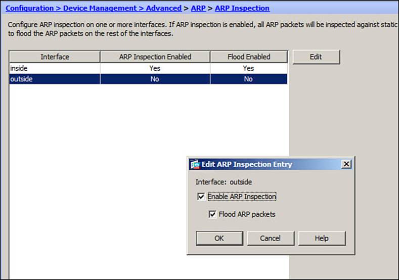
Figure 12-12. Enabling ARP Inspection in ASDM
Once ARP Inspection is enabled, the ASA takes one of the following actions as ARP reply packets are received:
• If the MAC address and the IP address are both found in a single ARP table entry, the ARP reply must be valid and therefore is allowed to pass through the ASA.
• If either the MAC address or the IP address is found in the ARP table, but not both in a single entry, the ARP reply contains invalid or spoofed information. Therefore, it is dropped and not forwarded through the ASA.
• If neither MAC address nor IP address is found in the ARP table, you can select the action as either flood (forward or flood the ARP packet out the other firewall interface so it can reach its destination) or no-flood (drop the ARP packet without forwarding it). By default, the floodaction is assumed.
If you choose to use the CLI instead, you can use the following command to define each static ARP entry. To clear a static ARP entry, repeat the command by beginning with the no keyword.
ciscoasa(config)# arp interface ip_address mac_address
By default, ARP inspection is disabled on all ASA interfaces. You can enable it on an ASA interface by entering the following command:
ciscoasa(config)# arp-inspection interface enable [flood | no-flood]
As an example, suppose you want to use ARP inspection in the scenario shown in Figure 12-6. The only two valid hosts are the router and the inside host, so you should configure static ARP entries for them. You could use the commands listed in Example 12-6 to prevent ARP spoofing attacks.
Example 12-6. Configuring ARP Inspection
ciscoasa(config)# arp inside 192.168.100.222 0000.2222.2222
ciscoasa(config)# arp outside 192.168.100.1 0000.1111.1111
ciscoasa(config)# arp-inspection inside enable
ciscoasa(config)# arp-inspection outside enable
You can verify the ARP inspection status on each interface with the show arp-inspection command. In Example 12-7, ARP inspection is enabled on both ASA interfaces.
Example 12-7. Verifying ARP Inspection Status
ciscoasa# show arp-inspection
interface arp-inspection miss
----------------------------------------------------
outside enabled flood
inside enabled flood
ciscoasa#
Disabling MAC Address Learning
In transparent firewall mode, an ASA will learn MAC addresses as they are received on either of its interfaces. This process works fine as long as hosts place their actual MAC addresses in the source address field of packets they send. The ASA’s MAC address table will be populated with results that can be trusted.
Suppose a malicious host is located on the outside of the ASA, as shown in Figure 12-13. Before the malicious host begins it work, the inside host has sent a packet and the ASA has learned that its source MAC address (0000.2222.2222) is located on the inside interface.
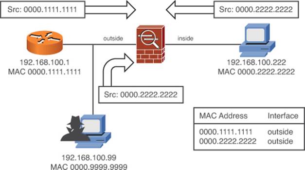
Figure 12-13. Attack Involving Spoofed MAC Addresses
Now, the malicious host is free to begin sending its own packets, but with spoofed MAC addresses in the source MAC address field. By sending a packet with source address 0000.2222.2222, the host can force the ASA to learn what is actually the inside host’s address on the outside interface. At this point, any packets arriving from the outside and destined for the inside host will simply be dropped because the host’s MAC address has been learned on the outside.
The malicious host might not stop with just one spoofed MAC address. It might also send so many packets with spoofed addresses that the ASA’s MAC address table is overrun. In effect, this would be a denial-of-service attack on the ASA, rendering it unable to forward any packets correctly.
To prevent MAC address spoofing attacks, you can disable MAC address learning completely. Without the capability to learn dynamically, the ASA must use statically configured MAC address entries instead. MAC address learning is configured on a per-interface basis.
You can use ASDM to configure static MAC address entries. Go to Configuration > Device Management > Advanced > Bridging and select MAC Address Table. Click the Add button to create a new static MAC address table entry, and then specify the interface name and the MAC address. Figure 12-14 shows two static entries that correspond to the scenario depicted in Figure 12-13.
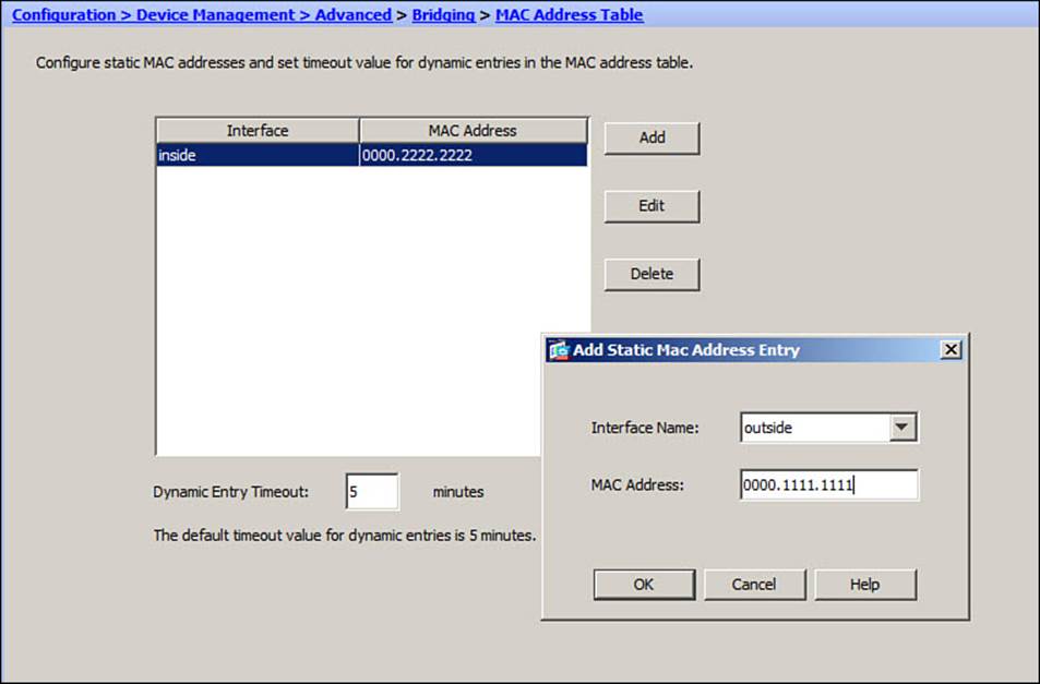
Figure 12-14. Creating Static MAC Address Table Entries in ASDM
Next, disable MAC address learning by selecting Bridging > MAC Learning. You can disable or enable MAC address learning on each interface individually. Select an interface, and then click the Enable or Disable button. In Figure 12-15, learning has been disabled on the inside interface.
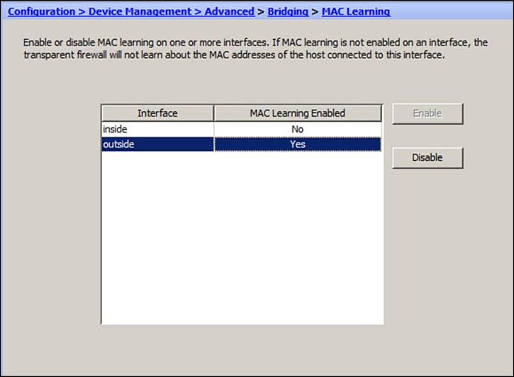
Figure 12-15. Disabling MAC Address Learning in ASDM
To use the CLI instead, configure a static MAC address entry by specifying the interface and MAC address with the following command:
ciscoasa(config)# mac-address-table static interface mac_address
Then, disable MAC learning on an interface:
ciscoasa(config)# mac-learn interface disable
Example 12-8 lists the commands necessary to disable MAC address learning and build two static entries for the two legitimate devices, as depicted in Figure 12-13.
Example 12-8. Disabling MAC Address Learning
ciscoasa(config)# mac-learn inside disable
ciscoasa(config)# mac-learn outside disable
ciscoasa(config)# mac-address-table static outside 0000.1111.1111
ciscoasa(config)# mac-address-table static inside 0000.2222.2222
To verify the MAC address learning status and to display the contents of the MAC address table, you can use the show mac-learn and show mac-address-table commands, respectively.
Exam Preparation Tasks
As mentioned in the section, “How to Use This Book,” in the Introduction, you have a couple of choices for exam preparation: the exercises here, Chapter 17, “Final Preparation,” and the exam simulation questions on the CD-ROM.
Review All Key Topics
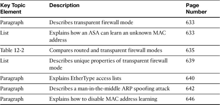
Review the most important topics in this chapter, noted with the Key Topic icon in the outer margin of the page. Table 12-3 lists a reference of these key topics and the page numbers on which each is found.
Table 12-3. Key Topics for Chapter 12
Define Key Terms
Define the following key terms from this chapter and check your answers in the glossary:
routed firewall mode
transparent firewall mode
bump-in-the-wire
EtherType access list
ARP inspection
MAC address learning
Command Reference to Check Your Memory
This section includes the most important configuration and EXEC commands covered in this chapter. It might not be necessary to memorize the complete syntax of every command, but you should be able to remember the basic keywords that are needed.
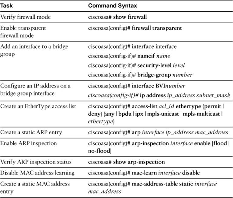
To test your memory of the commands, cover the right side of Table 12-4 with a piece of paper, read the description on the left side, and then see how much of the command you can remember.
Table 12-4. Commands Related to ASA Interface Configuration and Verification
The FIREWALL exam focuses on practical, hands-on skills that are used by a networking professional. Therefore, you should be able to identify the commands needed to configure and test an ASA feature.
All materials on the site are licensed Creative Commons Attribution-Sharealike 3.0 Unported CC BY-SA 3.0 & GNU Free Documentation License (GFDL)
If you are the copyright holder of any material contained on our site and intend to remove it, please contact our site administrator for approval.
© 2016-2026 All site design rights belong to S.Y.A.