CCNP Security FIREWALL 642-618 Official Cert Guide (2012)
Chapter 14. Deploying High Availability Features
This chapter covers the following topics:
• ASA Failover Overview: This section provides an overview of high availability or failover operation between two compatible Cisco ASA devices.
• Configuring Active-Standby Failover Mode: This section explains the configuration steps that are needed for two ASAs to operate as an active-standby failover pair.
• Configuring Active-Active Failover Mode: This section covers the configuration steps that are needed when two ASA are to operate as an active-active failover pair.
• Tuning Failover Operation: This section discusses the ways you can fine-tune threshold conditions that trigger an ASA pair to failover. A method to handle asymmetrically routed packets is also explained, along with the commands needed to manually control failover roles.
• Verifying Failover Operation: This section describes the command output you can use to observe and verify failover operation in an ASA failover pair.
• Leveraging Failover for a Zero Downtime Upgrade: This section explains the sequence of steps needed to upgrade the operating system on a live failover pair of ASAs, without causing network downtime in the process.
When a single Cisco Adaptive Security Appliance (ASA) is configured with security features and policies, it can offer reliable protection—as long as it continues to run properly, has a continuous source of power, and has consistent network connectivity. Power and connectivity are resources that are provided outside the ASA, but the ASA itself might experience a hardware or software failure, making it a single point of failure.
You can configure two ASAs as a failover pair, allowing them to operate in tandem. The result is greater reliability because one or both ASAs are always available for use. This chapter covers the configuration and operation of a high availability pair.
“Do I Know This Already?” Quiz
The “Do I Know This Already?” quiz allows you to assess whether you should read this entire chapter thoroughly or jump to the “Exam Preparation Tasks” section. If you are in doubt about your answers to these questions or your own assessment of your knowledge of the topics, read the entire chapter. Table 14-1 lists the major headings in this chapter and their corresponding “Do I Know This Already?” quiz questions. You can find the answers in Appendix A, “Answers to the ‘Do I Know This Already?’ Quizzes.”
Table 14-1. “Do I Know This Already?” Section-to-Question Mapping
Caution
The goal of self-assessment is to gauge your mastery of the topics in this chapter. If you do not know the answer to a question or are only partially sure of the answer, you should mark that question as wrong for purposes of the self-assessment. Giving yourself credit for an answer you correctly guess skews your self-assessment results and might provide you with a false sense of security.
1. Which one of the following best describes the high availability attributes of active-standby failover mode?
a. Interface redundancy
b. Device redundancy with load balancing
c. Context redundancy
d. Device redundancy with no load balancing
2. What is the maximum number of ASAs that can be configured together for failover operation?
a. 1
b. 2
c. It depends on the license purchased.
d. An unlimited number
3. When an ASA is configured to operate in multiple context mode, which one of the following failover methods can be used?
a. No failover mode
b. Single failover mode
c. Active-standby mode
d. Active-active mode
4. Suppose two ASAs are configured as a failover pair. Which one of the following best describes what happens to an interface on the standby unit when a failover occurs and it takes on the active role?
a. The interface IP address changes to match the previous active unit’s address, but the MAC address stays the same.
b. The interface IP address and MAC address both change to match that of the previous active unit.
c. The interface MAC address changes to match the previous active unit’s address, but the IP address stays the same.
d. Nothing; both the interface IP and MAC addresses stay the same.
5. In active-active failover mode, security contexts can be assigned to how many failover groups?
a. 1
b. 2
c. One per context
d. An unlimited number
6. Which one of the following links is used to replicate ASA configuration commands?
a. LAN failover link
b. Standby link
c. Stateful failover link
d. Cluster link
7. Which of the following is not something that is synchronized between failover peers? (Choose all that apply.)
a. Address translation entries
b. ARP table entries
c. TCP connections
d. Running configuration changes
e. Operating system image files
8. The following configuration commands have been entered on an ASA, yet the failover process doesn’t seem to be working. What command could be added to make failover work?
ciscoasa(config)# failover lan unit primary
ciscoasa(config)# failover lan interface LANfo Ethernet0/2
ciscoasa(config)# failover interface ip LANfo 192.168.200.1 255.255.255.0
standby 192.168.200.2
ciscoasa(config)# failover key B1gs3cr3tk3y
ciscoasa(config)# failover link stateful Ethernet0/3
ciscoasa(config)# failover interface ip stateful 192.168.201.1 255.255.255.0
standby 192.168.201.2
ciscoasa(config)# failover replication http
a. failover active
b. failover link stateful ethernet0/4
c. no failover standby
d. failover
9. When stateful failover is configured, which one of the following actions should be taken to synchronize HTTP connection state information?
a. Nothing; HTTP connections are always synchronized.
b. Enter the failover http command.
c. Enter the failover replication http command.
d. Enter the failover link http command.
10. Under which of the following conditions can an ASA preempt its failover peer to take over the active role?
a. Never; the failover role cannot change until the next failure occurs.
b. The preempt global configuration command has been entered.
c. The preempt failover group configuration command has been entered.
d. Failover peers can always preempt to take over the active role.
11. By default, how long does it take for a dead ASA peer to be detected to trigger a failover?
a. 1 second
b. 5 seconds
c. 15 seconds
d. 30 seconds
12. By default, how many ASA interfaces must fail before a failover is triggered?
a. 1
b. 2
c. None; failover occurs only if an ASA unit fails.
d. All interfaces
13. Which one of the following commands should be used to determine the current failover status?
a. show failover
b. show failover status
c. show active
d. show standby
14. A new ASA software image has been released. Which one of the following describes the best upgrade process you should use to upgrade a failover pair in your network?
a. Download the new image to both units, and then reload them both at the same time.
b. Download the new image to both units; power cycle one unit, and then power cycle the other unit.
c. Download the new image to both units; reload the standby unit first, and then reload the active unit.
d. Download the new image to both units; reload the standby unit first, toggle the active and standby roles, and then reload the new standby unit.
Foundation Topics
With its rich, versatile feature set, a single ASA can provide robust protection for a network. If that ASA experiences a failure of some sort, it might not be able to inspect and pass traffic until it is repaired. As a remedy, this chapter covers the methods you can use to configure two ASAs as a failover pair, providing redundancy and high availability.
ASA Failover Overview
Two ASAs can be configured to operate as a high availability or “failover” pair. The idea is to leverage two separate devices so that one of them is always available in case the other one fails. Naturally, there is a possibility that both ASAs might fail within the same time-frame, but your goal as a network professional should be to minimize that chance. For example, you might want to install each ASA in a different building to give them physical separation, in case power fails in one building for an extended time.
Cisco ASAs support two forms of failover:

• Active-standby: One ASA takes on the active role, handling all the normal security functions. The other ASA stays in standby mode, ready to take over the active role in the event of a failure. The active-standby failover mode provides device redundancy.
• Active-active: When the ASAs are running multiple security contexts, the contexts can be organized into groups. One ASA is active for one group of contexts, and the other ASA is active for another group. In effect, both ASAs are actively involved in providing security functions, but not in the same security context simultaneously. The active-active failover mode provides both device redundancy and load balancing across contexts.
Failover Roles
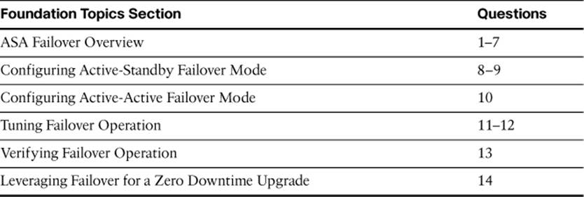
To coexist as a failover or redundant pair, two ASAs must be an identical model and must coordinate their failover roles. In active-standby failover, one ASA must function as the active unit, handling all traffic inspection at any given time. The other ASA must always sit idle, waiting to take over the active role. Figure 14-1 illustrates this arrangement. The topmost ASA is active, while the bottommost ASA is in standby mode.
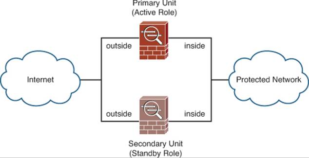
Figure 14-1. Active-Standby Failover Mode
Notice that the ASA pair must share identical sets of interfaces. For example, each unit has an inside and an outside interface, and the similar interfaces must be connected together. This is for two reasons:
• The standby unit must be ready to take over handling traffic at any time, so its interfaces must be connected and ready to use.
• The two ASAs monitor each other’s health by communicating over each of their interfaces.
If a failure is detected on the active unit, the two ASAs effectively swap roles, as shown in Figure 14-2. The lower ASA was previously in the standby mode, but has moved into the active role.
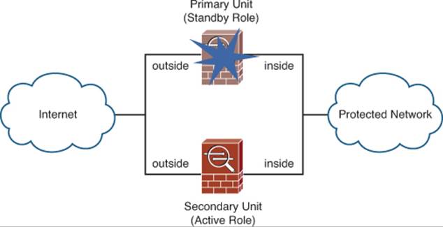
Figure 14-2. Failure Detected in Active-Standby Failover Mode
Once a failure is detected, the ASAs swap roles until the next failure. If an ASA moves into the standby role, it is not permitted to preempt its peer and take over the active role again—unless the active ASA has a failure of its own. This creates a stable mechanism where the ASAs toggle roles only when failures occur.
Each ASA maintains a unique MAC address and a unique IP address on each of its interfaces. In addition to swapping the active and standby roles, the ASAs must also swap MAC and IP addresses so that the active unit always uses consistent and predictable values—regardless of which physical unit is active at any time. Figure 14-3 illustrates this process. The address swap occurs on every ASA interface except the LAN failover, which always remains unchanged.
Figure 14-3. Address Swapping During Failover
The MAC and IP addresses used for the active role are taken from the burned-in MAC addresses or the values that might be configured on only one of the two ASAs. Therefore, one of the two units must be configured as the primary unit. The other ASA becomes the secondary unit, which supplies the addressing values for the standby role. The primary and secondary designations only determine the active and standby addresses—not the active and standby roles.
When two ASAs are configured to operate in active-active failover mode, they still alternate their roles so that one unit is active and one is in standby; however, the active-standby combination is carried out on a per-failover group basis, with each ASA running failover groups containing multiple security contexts. If the active-standby roles are alternated across different security contexts, both units can actively inspect traffic at the same time—hence the term active-active failover, where neither unit is required to sit completely idle.
Figure 14-4 illustrates the active-active concept, in which each ASA is configured to run three separate security contexts: ContextA, ContextB, and ContextC. Each context in the primary ASA can take on either the active or standby role, while the corresponding context in the secondary ASA takes on the alternate role. In the figure, the primary ASA has the active role for ContextA and ContextC; the secondary ASA is active for ContextB.
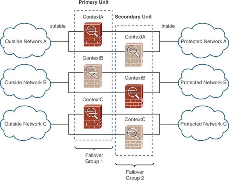
Figure 14-4. Active-Active Failover Mode
Notice how the failover roles of each context can be collected into two logical failover groups, corresponding to the physical ASA unit, as listed in Table 14-2. At any given time, one ASA will have the active role for all contexts that are assigned to its failover group, while the other ASA will be active for all contexts assigned to the other failover group.
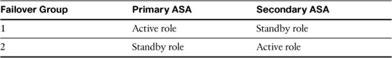
Table 14-2. Failover Group Roles in Active-Active Failover Mode
During a failure in active-active failover mode, the two ASAs effectively swap roles, but only on a failover group basis. In Figure 14-5, the entire primary ASA has failed, rendering both of its contexts in failover group 1 useless. The secondary ASA then takes on the active role for failover group 1 (ContextA and ContextC), although it was already active for failover group 2 (ContextB).
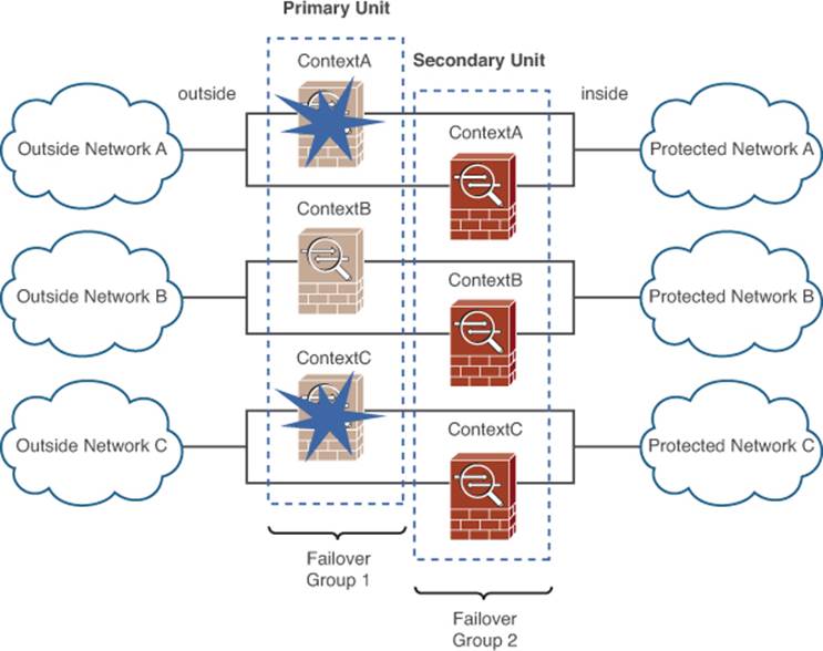
Figure 14-5. Failure Detected in Active-Active Failover Mode
In either active-standby or active-active mode, a failover pair of ASAs must have a special-purpose link set aside for failover communication between them. The LAN-based failover link, as shown in Figure 14-6, is used to check on the health of a failover peer ASA and to pass configuration updates and commands between peers.
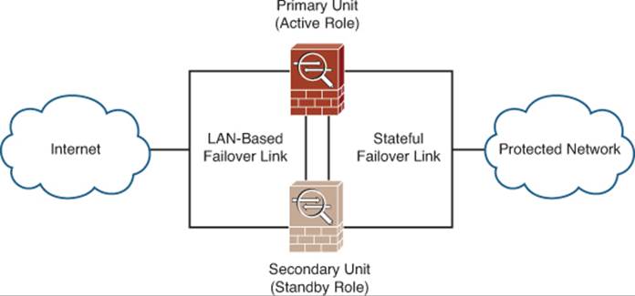
Figure 14-6. Links Used for Failover Communication
Note
The LAN failover interface should be connected to a switch that is separate from other ASA interfaces so that the ASAs can detect a switch failure that affects regular ASA interfaces without affecting the LAN failover interface and the failover process itself. To add even more resilience, you can configure the LAN failover interface using a pair of redundant interfaces, each connected to a different switch.
The ASA configurations are always maintained on the active unit. As you make changes to the running configuration, the commands are automatically synchronized from the active unit to the standby unit. You can force the running configuration synchronization by entering the write standby command on the active unit.
The startup configuration, however, is not automatically synchronized. The copy running-config startup-config command saves the running configuration to flash memory on the active unit and then to the flash on the standby unit.
Each ASA maintains its own flash file system, but files are not replicated between the units as a part of failover. This means that each ASA maintains its own operating system and ASDM images. To upgrade a software image, you must upgrade each of the failover peers independently. The “hitless upgrade” or “zero downtime upgrade” feature allows failover operation to continue, even while the two ASAs are running different, but compatible, software releases. The upgrade process is covered in more detail in the section, “Leveraging Failover for a Zero Downtime Upgrade.”
By default, an ASA failover pair operates in a stateless failover mode. The active unit stays busy building and tearing down address translations and connections, but does not inform the standby unit at all. If the active unit fails, none of the active UDP or TCP connections will be preserved because the standby unit doesn’t have anything in its connection state tables. Therefore, hosts will have to reinitiate any connections that they were using at the time.
To make the failover operation more seamless, you can configure an ASA pair to use stateful failover instead. A second special-purpose stateful failover link must be used to pass connection state information between failover peers, so that the standby unit can keep its translation and connection tables in sync with the active unit. Figure 14-6 shows this link. If the active unit fails, the standby unit will be fully equipped to pick up all existing stateful inspections so that no connections will be lost.
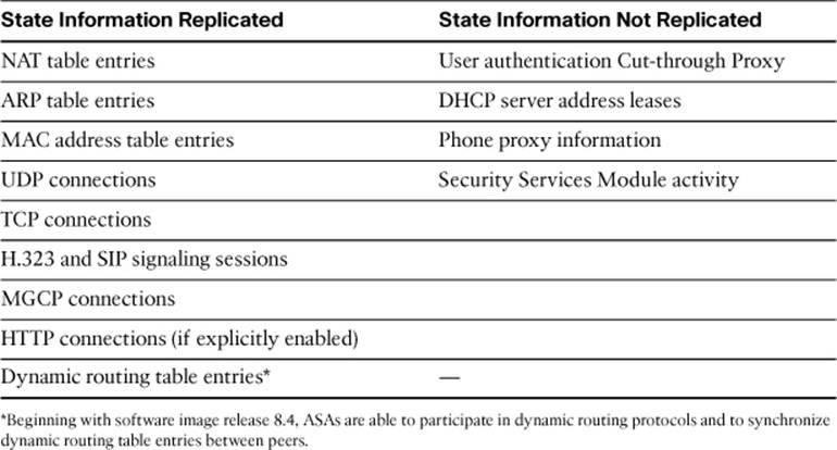
Stateful failover synchronizes many types of information between the active and standby units. Table 14-3 lists the types of state information that are replicated and the types that are not. You should leverage stateful failover whenever possible, to make the failover process as seamless as possible.
Table 14-3. State Information Synchronization Between Stateful Failover Peers
When stateful failover is used, you can dedicate one interface to LAN failover and another to stateful failover, or you can use a single interface to share both LAN failover and stateful failover information. The stateful failover data stream is usually much larger than the LAN failover data stream because of the large number of connections that come and go as traffic passes through the ASA pair. However, you should never use a regular data interface to carry stateful failover information, to prevent high volumes of data from crowding out critical failover updates. You should set aside the fastest interface that is available for stateful failover.
Be aware that even with stateful failover enabled, HTTP connection state information is not replicated between the active and standby units by default. You can remedy that by enabling HTTP connection synchronization to force the active unit to update the standby unit as HTTP and HTTPS connections are built and torn down.
Detecting an ASA Failure
Two ASAs must be configured with their primary and secondary failover identities, so that the active unit can determine which MAC and IP addresses to use. But what determines which unit takes on the active role? Each ASA must go through an election process when it boots.
By listening on the LAN failover interface, an ASA can determine which state its failover peer is in and can decide which role to use for itself. The failover peers can also compare their “health” rating by seeing if all interfaces are up and if the Security Services Module (SSM) is installed and functional.
The election process takes place as follows:
• If a peer is detected, is trying to negotiate its own role, and is equally healthy as the booting ASA, the primary unit will become active and the secondary unit will become standby.
• If a peer is detected, is trying to negotiate its own role, but is not equally healthy, the healthier of the two ASAs will become active.
• If a peer is detected and it already has the active role, the booting ASA will become standby.
• If no peer is detected at all, the booting ASA will become active.
• If the booting ASA becomes active, but later detects its peer that is also active, it will begin negotiating roles with its peer to elect only one active role.
Once failover is enabled and active, the two ASA peers continuously communicate and monitor each other. Hello packets are sent at regular intervals over the LAN failover interface and every interface that is configured to be monitored. By listening for hello packets from a peer device, an ASA can determine the health of its peer.
An ASA monitors the health of its peer according to the following rules:
• As long as hellos are received over the LAN failover interface, the peer must be alive and no failover occurs.
• If hellos are not received over the LAN failover interface, but hellos are received on other monitored interfaces, the peer must be alive and no failover occurs. Only the LAN failover interface is declared to be “failed” and should be repaired as soon as possible.
• If no hellos are received on any interface for a hold time interval, the peer is declared to be “failed” and failover occurs.
By default, hello packets are sent over the LAN failover interface every 1 second. The default hold timer is 15 seconds. You can shorten the failover unit poll (hello) and hold timers so that a failure is detected sooner, if desired. The failover timers are covered in more detail in the section, “Tuning Failover Operation.”
Each interface of one ASA must connect to the same network as the corresponding interface of the peer ASA. Hello packets are also sent on all interfaces that are configured to be monitored for failover, so that an ASA can determine the health of each interface on its peer.
The poll and hold times used by the interface-based hello monitoring are different from those used by the unit-based hello monitoring on the LAN failover interface. By default, interface hellos are sent and polled every 5 seconds, with an interface hold timer of five times the interface poll time.
If hello packets are not seen on a monitored interface within half of the hold time, that interface is moved into a “testing” mode to determine if a failure has occurred. The peer ASA is notified of the test via the LAN failover interface.
Interfaces in the “testing” mode are moved through the following sequence of tests:
1. Interface status: The interface is failed if the link status is down.
2. Network activity: If no packets are received over a 5-second interval, the next testing phase begins; otherwise, the interface can still be used.
3. ARP: The interface stimulates received traffic by sending ARP requests for the ten newest entries in the ASA’s ARP table. If no traffic is received in 5 seconds, the next testing phase begins.
4. Broadcast ping: Traffic is stimulated by sending an ICMP echo request to the broadcast address on the interface. If no replies are received over a 5-second interval, the interface is marked in a “failed” state; however, if the same interface on the peer ASA also fails the test, then the interface is marked in an “unknown” state because an actual failure cannot be determined.
At the conclusion of the tests, the two ASAs attempt to compare their status. If the active unit has more failed interfaces than a configured threshold, a failover occurs.
Once a monitored interface is marked as “failed,” it will become operational again as soon as any traffic is received on it.
Configuring Active-Standby Failover Mode
You can use ASDM to configure and enable failover. ASDM offers a wizard that will step through the configuration and push failover commands to the secondary unit automatically. Otherwise, you can configure failover parameters under separate ASDM tabs on the primary and secondary units manually. Both strategies are covered in the sections that follow.
As a configuration example, the failover scenario shown in Figure 14-7 is to be implemented. The inside and outside MAC addresses should be configured to the values shown in the figure. By default, all interfaces will be monitored for failover; because the Management0/0 interface is not used in this scenario, it should not be monitored.
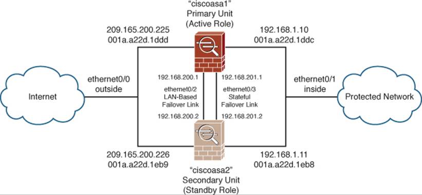
Figure 14-7. Network Diagram for the Example Active-Standby Failover Scenario
Configuring Active-Standby Failover with the ASDM Wizard
To use the wizard, start ASDM on the primary failover unit. Navigate to Configuration > Device Management > High Availability, and then select HA/Scalability Wizard. In the window shown in Figure 14-8, click the Launch High Availability and Scalability Wizard button.
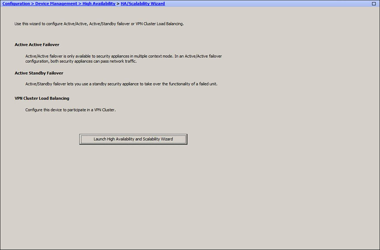
Figure 14-8. Accessing the High Availability Wizard to Configure Failover
Next, click the Configure Active/Standby Failover radio button, as shown in Figure 14-9, and then click Next.
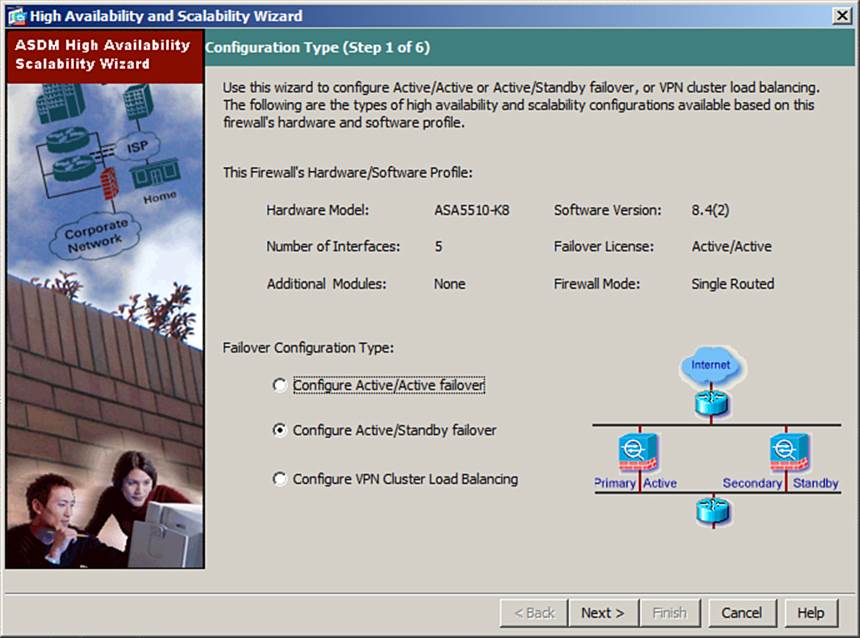
Figure 14-9. Beginning Active-Standby Failover Configuration
The wizard will begin by asking for the failover peer’s IP address. Enter the address of one of the secondary unit’s interfaces. In Figure 14-10, the address of the secondary inside interface has been entered. When you click the Next button, ASDM will go through a series of seven steps to communicate with the secondary unit and to make sure the two units are compatible for failover. The steps begin with question marks, as shown in the figure, and progress to green check marks after the failover tests are successful.
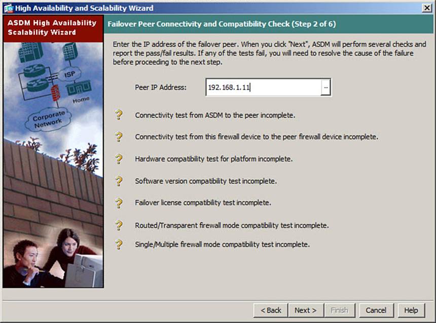
Figure 14-10. Testing Failover Compatibility in the ASDM Wizard
Before these tests can succeed, you must configure the secondary unit with enough information to be live on the network and to respond to the tests. At a minimum, the secondary unit must have at least one interface configured with an IP address, and the unit must allow remote access on that interface. ASDM will prompt for a username and password so that it can log in to the secondary unit remotely and parse through its configuration.
Next, the wizard will ask you to enter information about the LAN failover link and the stateful failover link. You will need to identify the interfaces and assign IP addresses to the active and standby units. These steps are shown in Figures 14-11 and 14-12. Be sure to choose the appropriate stateful failover link arrangement, whether the link will be shared with LAN failover or be a separate link.
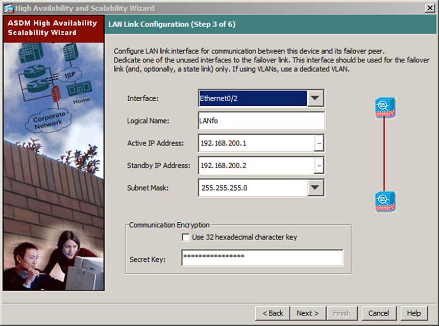
Figure 14-11. Configuring the LAN Failover Link in the ASDM Wizard
As a final step, the wizard will display a list of regular data interfaces on the ASA, as shown in Figure 14-13. You need to configure the active and standby IP addresses for each. To change an address, double-click in the address field and enter a new value. In the rightmost column, select each interface that should be monitored for failover.
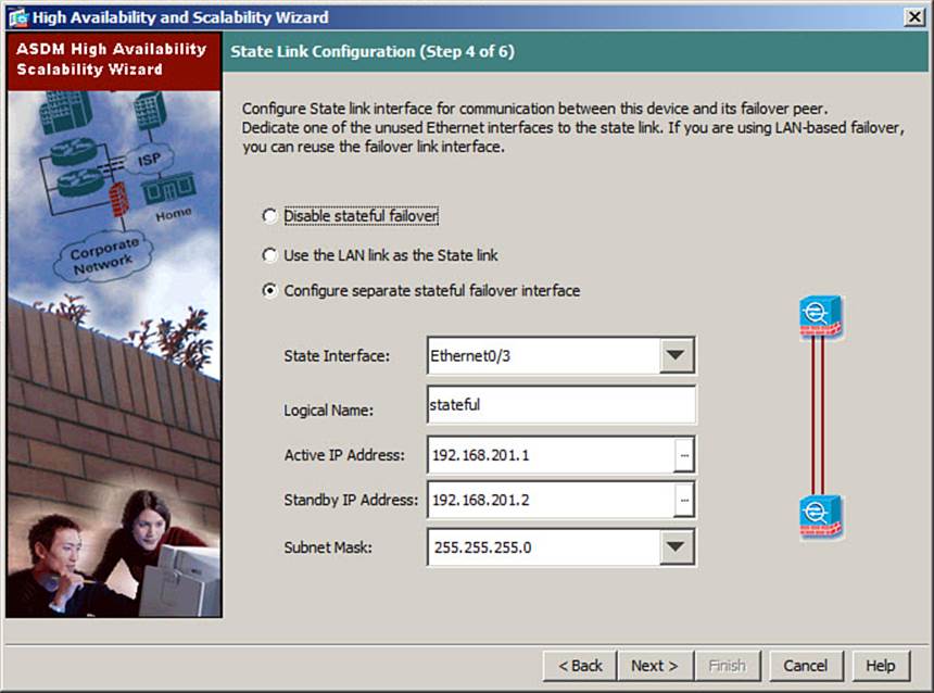
Figure 14-12. Configuring the Stateful Failover Link in the ASDM Wizard
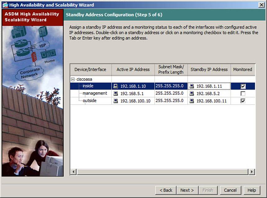
Figure 14-13. Configuring ASA Interfaces for Failover in the ASDM Wizard
Once you click the Next button, the wizard will display all the failover parameters it will send to the secondary ASA. After you review the list, click the Finish button. ASDM will send the commands and wait about 30 seconds for the two units to recognize their failover peer relationship and synchronize their configurations and interface states.
Configuring Active-Standby Failover Manually in ASDM
To configure each aspect of active-standby failover, start ASDM on the primary failover unit. Navigate to Configuration > Device Management > High Availability, and then select Failover. You can enable failover and enter information about the LAN failover and stateful failover links on the Setup tab, as shown in Figure 14-14.
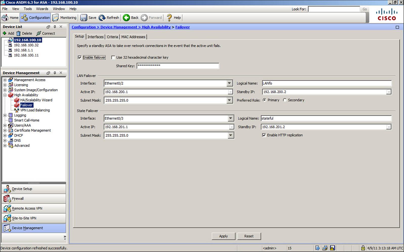
Figure 14-14. Configuring the LAN Failover and Stateful Failover Interfaces
Click the Interfaces tab to configure active and standby IP addresses on each data interface, as shown in Figure 14-15. You can also select which interfaces will be monitored for failover.
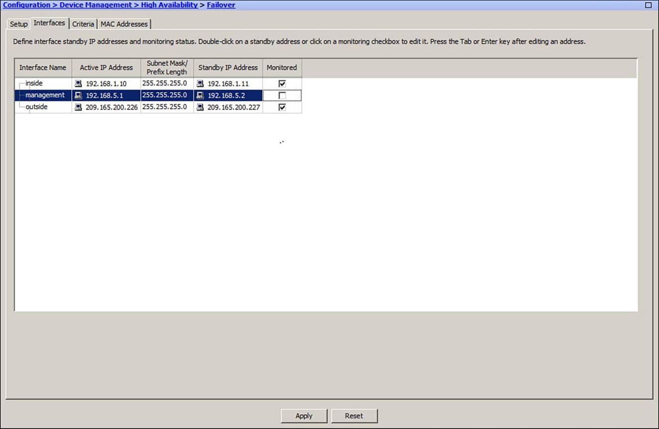
Figure 14-15. Configuring Failover Operation on Data Interfaces
If you decide to configure predetermined MAC addresses on some normal data interfaces, you can do that under the MAC Addresses tab. Click the Add button to select an interface. As shown in Figure 14-16, choose an interface from the drop-down list and enter both an active and a standby MAC address.
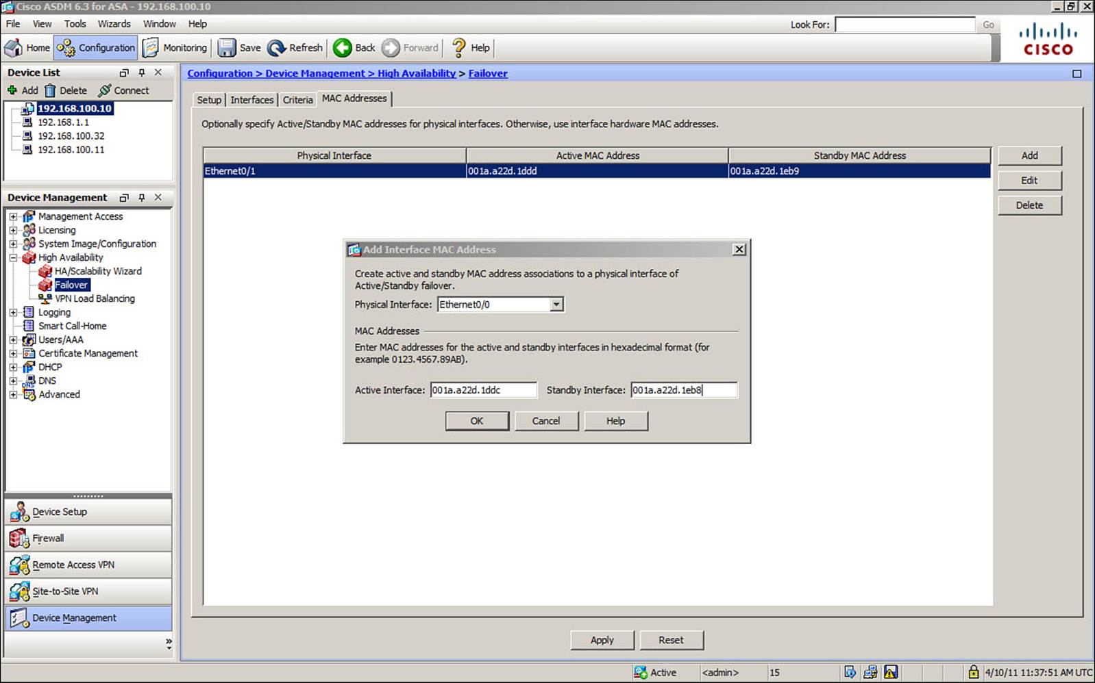
Figure 14-16. Configuring Failover MAC Addresses on Data Interfaces
You can make adjustments to the failover timers and health monitoring thresholds on the Criteria tab. These configuration changes are discussed in detail in the section, “Tuning Failover Operation.”
Finally, you will need to start ASDM on the secondary ASA and complete the failover configuration there.
Configuring Active-Standby Failover with the CLI
You can use the CLI to configure active-standby failover mode according to the following steps:
Step 1. Configure the primary failover unit.
Step 2. Configure failover on the secondary device.
Step 1: Configure the Primary Failover Unit
Begin by connecting to the primary unit and identifying it as such with the following command:
ciscoasa(config)# failover lan unit primary
Identify the LAN failover interface by its logical and physical names with the failover lan interface command. Then specify the IP address that will be used on the active and standby units with the failover interface ip command. You should also configure LAN failover encryption by giving an encryption key string with the failover key command. The key string is an arbitrary text string of up to 63 characters or a string of exactly 32 hex digits.
The commands needed to configure the LAN failover interface and to enable failover are as follows:
ciscoasa(config)# failover lan interface int_name [physical_int]
ciscoasa(config)# failover interface ip int_name ip_address mask standby
ip_address
ciscoasa(config)# failover key {key-string | hex key}
ciscoasa(config)# failover
Next, select a stateful failover interface with the failover link command. Assign an IP address for the active and standby units with the failover interface ip command. Enter the failover replication http command if you want stateful failover of HTTP connections.
ciscoasa(config)# failover link int_name [physical_int]
ciscoasa(config)# failover interface ip int_name ip_address mask standby
ip_address
ciscoasa(config)# failover replication http
For each interface that will carry normal data, you will need to configure the active and standby unit IP addresses. You can do this with the ip address interface configuration command, followed by the standby keyword, as follows:
ciscoasa(config-if)# ip address active_addr subnet_mask standby standby_addr
Normally, the active and standby units use their own burned-in MAC addresses for a regular data interface and inform each other through failover messages. The active MAC address can stay consistent, regardless of which unit has the active role. However, in the rare “corner” case where the standby unit is booted alone, it will use its own burned-in address instead.
You can prevent this from happening by using the following global configuration command to set the active and standby unit MAC addresses to unique, predetermined values. You should use arbitrary unique values or the burned-in MAC addresses from the primary and secondary units, as shown in the show interface command output:
ciscoasa(config)# failover mac address int_name active_mac standby_mac
By default, every ASA interface will be monitored to detect a failure that might trigger a failover. If you want to exclude an interface from being monitored, enter the following command:
ciscoasa(config)# no monitor-interface int_name
Interface and health monitoring are covered in detail in the section, “Tuning Failover Operation.”
At this point, the primary unit is configured for failover and is waiting to detect a secondary failover unit. Because it has been configured first, the primary unit will take on the active failover role.
Step 2: Configure Failover on the Secondary Device
Connect to the secondary ASA and identify it as the secondary failover unit. Configure the LAN failover interface with the following commands:
ciscoasa(config)# failover lan unit secondary
ciscoasa(config)# failover lan interface int_name [physical_int]
ciscoasa(config)# failover interface ip int_name ip_address mask standby
ip_address
ciscoasa(config)# failover key {key-string | hex key}
ciscoasa(config)# failover
The final failover command enables the failover function. Once the primary and secondary units recognize each other, the secondary unit should take on the standby role. The LAN failover interface will be used to replicate configuration commands from the active to the standby unit—including most of the failover commands you have already entered. From this point on, you should enter all configuration changes only on the ASA that has the active role.
Refer to Figure 14-7 for a network diagram of a configuration example. The configuration commands listed in Example 14-1 are entered on the primary ASA, while the commands listed in Example 14-2 are entered on the secondary ASA.
Example 14-1. Configuring Failover on the Primary ASA
ciscoasa(config)# failover lan unit primary
ciscoasa(config)# failover lan interface LANfo Ethernet0/2
ciscoasa(config)# failover interface ip LANfo 192.168.200.1 255.255.255.0 standby
192.168.200.2
ciscoasa(config)# failover key B1gs3cr3tk3y
ciscoasa(config)# failover
!
ciscoasa(config)# failover link stateful Ethernet0/3
ciscoasa(config)# failover interface ip stateful 192.168.201.1 255.255.255.0
standby 192.168.201.2
ciscoasa(config)# failover replication http
!
ciscoasa(config)# interface Ethernet0/0
ciscoasa(config-if)# nameif outside
ciscoasa(config-if)# security-level 0
ciscoasa(config-if)# ip address 209.165.200.226 255.255.255.0 standby
209.165.200.227
ciscoasa(config-if)# exit
!
ciscoasa(config)# interface Ethernet0/1
ciscoasa(config-if)# nameif inside
ciscoasa(config-if)# security-level 100
ciscoasa(config-if)# ip address 192.168.1.10 255.255.255.0 standby 192.168.1.11
ciscoasa(config-if)# exit
ciscoasa(config)# failover mac address inside 001a.a22d.1ddd 001a.a22d.1eb9
ciscoasa(config)# failover mac address outside 001a.a22d.1ddc 001a.a22d.1eb8
ciscoasa(config)# no monitor-interface management0/0
Example 14-2. Configuring Failover on the Secondary ASA
ciscoasa(config)# failover lan unit secondary
ciscoasa(config)# failover lan interface LANfo Ethernet0/2
ciscoasa(config)# failover interface ip LANfo 192.168.200.1 255.255.255.0 standby
192.168.200.2
ciscoasa(config)# failover key B1gs3cr3tk3y
ciscoasa(config)# failover
Configuring Active-Active Failover Mode
Configuring active-active failover is similar to configuring active-standby mode. The two failover units need the same LAN failover and stateful failover link configurations, and the same active and standby addresses on each interface. However, each ASA must be assigned its primary or secondary role in each of the two failover groups. As well, each security context must be assigned to a failover group.
As an example, the failover scenario shown in Figure 14-17 is to be implemented. Three security contexts are used. Failover group 1 should contain the admin and ContextB contexts, with the primary ASA normally having the active role. Failover group 2 should contain only ContextA, normally active on the secondary ASA.
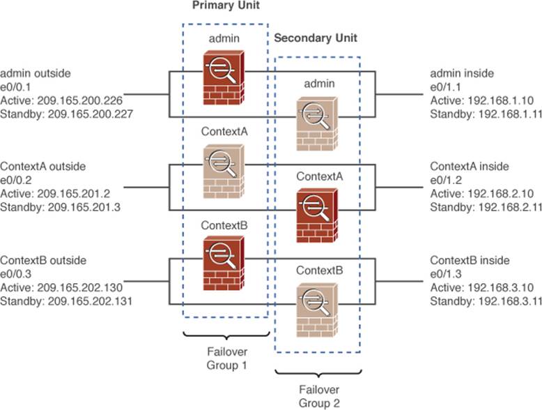
Figure 14-17. Network Diagram for the Example Scenario
Configuring Active-Active Failover in ASDM
You can use ASDM to configure active-active failover. As with active-standby failover, you can use the ASDM High Availability and Scalability Wizard to configure both the primary and secondary ASAs from the primary unit. To do that, double-click the System context in the device list. Then navigate to Configuration > Device Management > High Availability and select HA/Scalability Wizard.
Otherwise, you can configure active-active failover on the primary and secondary units manually. On the primary unit, double-click the System context in the device list, and then navigate to Configuration > Device Management > High Availability and select Failover.
On the Setup tab, shown in Figure 14-18, you can configure the LAN failover and stateful failover links, as well as enable failover.
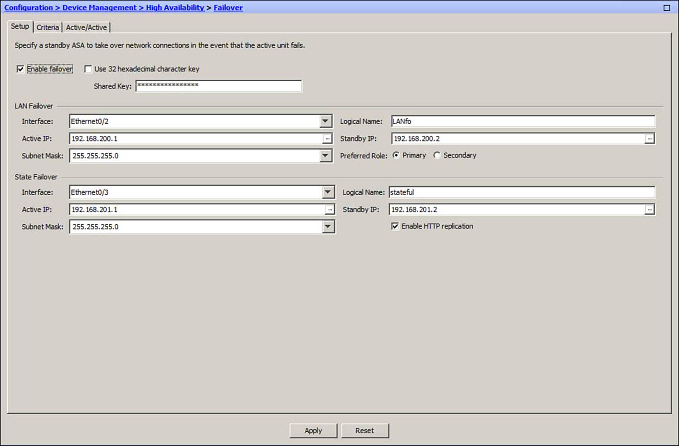
Figure 14-18. Configuring Failover Links for Active-Active Failover Mode
Under the Criteria tab, as shown in Figure 14-19, you can configure failover timers and health monitoring parameters. These are discussed in the section, “Tuning Failover Operation.”
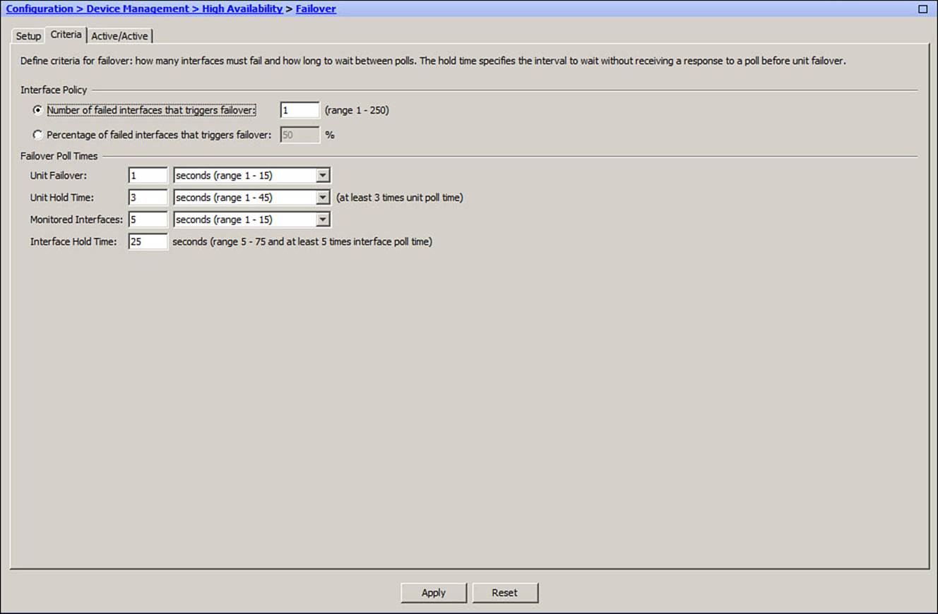
Figure 14-19. Configuring Failover Criteria in Active-Active Mode
Next, click the Active/Active tab to configure the ASA for its primary or secondary role in each failover group. Select a failover group from the list and click the Edit button to make changes. In Figure 14-20, the primary ASA has been configured to have the primary (normally active) role for failover group 1 and the secondary (normally standby) role for failover group 2.
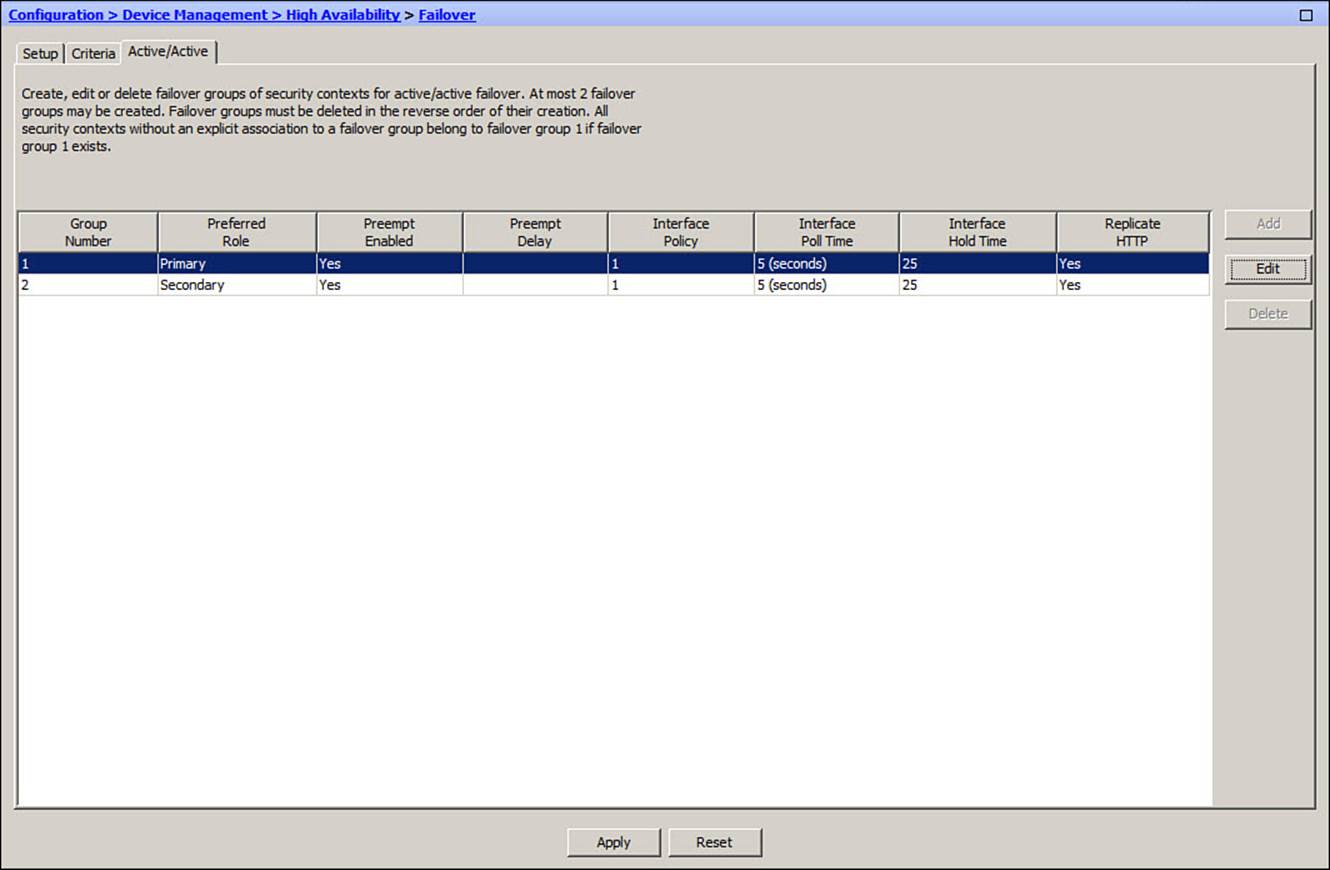
Figure 14-20. Configuring Failover Group Roles for Active-Active Failover Mode
Next, you will need to assign each security context to one of the two failover groups. By default, all contexts belong to failover group 1. Navigate to Configuration > Context Management and select Security Contexts. Each context that is configured on the ASA will be displayed in a list. To assign the failover group, select a context, click the Edit button, and then select a failover group, as shown in Figure 14-21.
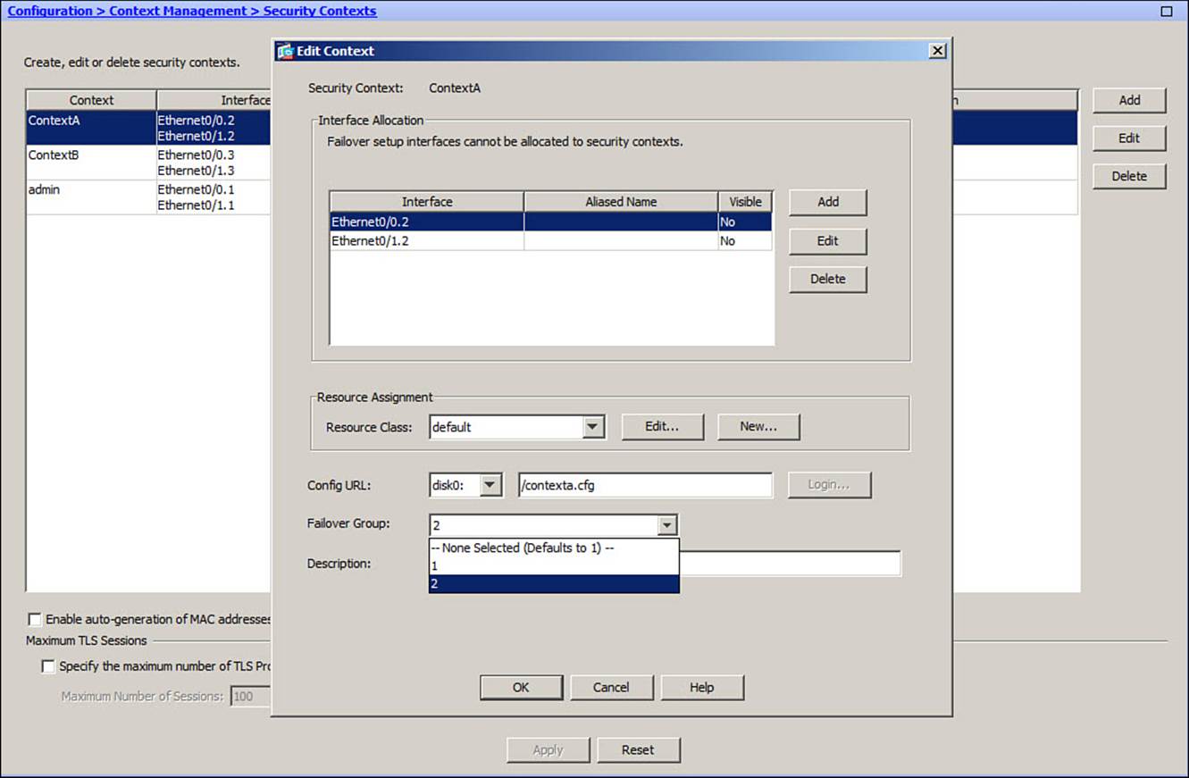
Figure 14-21. Assigning Security Contexts to Active-Active Failover Groups
Now that the primary ASA is configured for active-active failover operation, you must visit each context to configure the active and standby IP addresses on each interface. You can also configure interface monitoring. In the device list, double-click a context name, navigate to Configuration > Device Management, and select Failover. Figure 14-22 shows the interfaces in the admin context. You can double-click in any of the address fields to edit or change the IP address values.
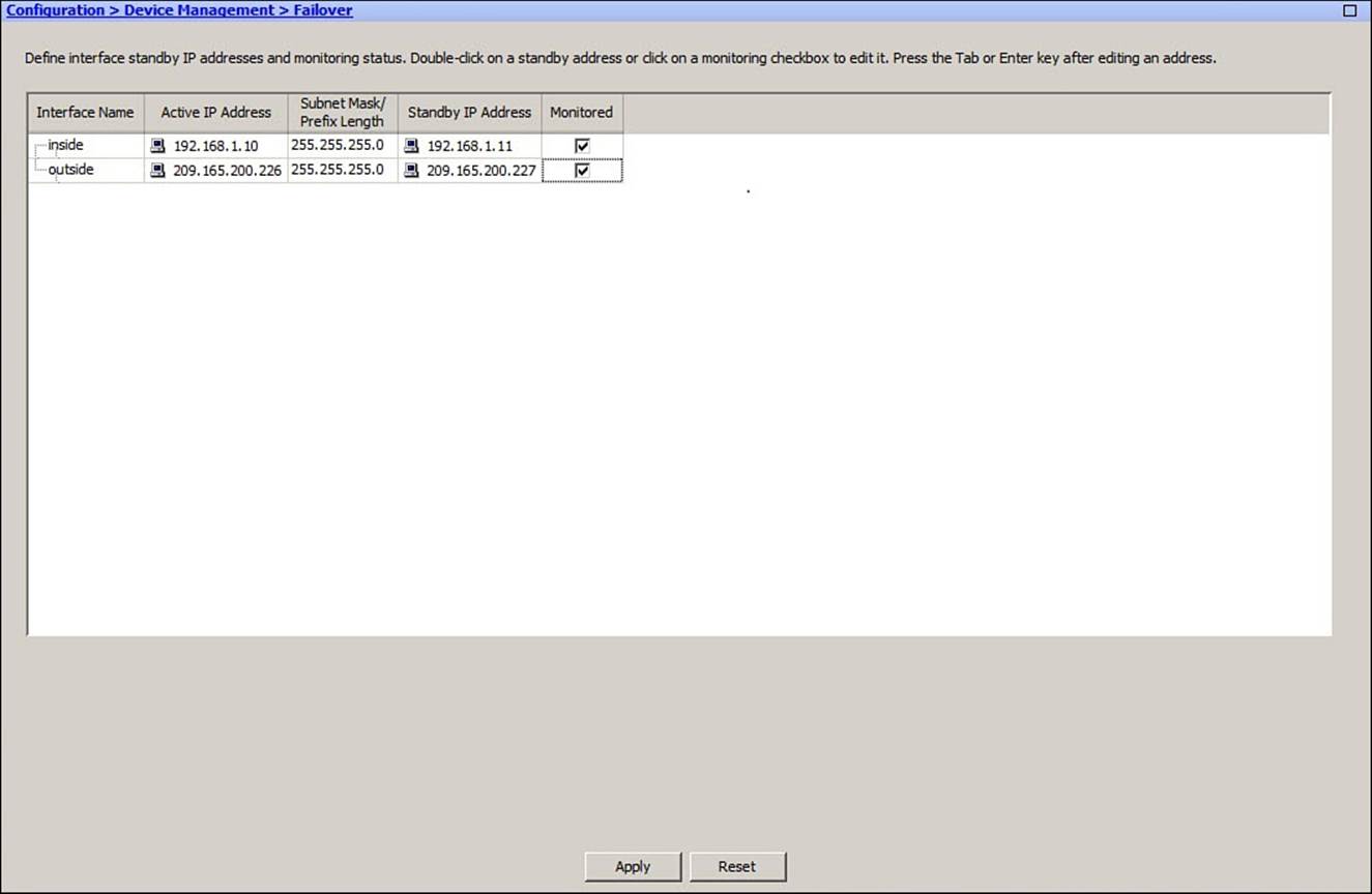
Figure 14-22. Configuring the Admin Context Interfaces for Active-Active Failover Mode
Finally, don’t forget to open an ASDM session with the secondary ASA and configure active-active failover in its system execution space. Once the LAN failover and stateful failover links are configured and failover is enabled, the primary unit will synchronize the system, admin, and any other context configuration with the secondary unit automatically. From that point on, any configuration changes you make should be entered on the ASA that currently has the active role for a specific security context.
Configuring Active-Active Failover with the CLI
You can use the CLI to configure active-active failover mode. Use the following steps to configure one ASA, and then move to the other ASA and repeat the steps there:
Step 1. Configure the primary ASA unit.
Step 2. Configure the secondary ASA unit.
Step 1: Configure the Primary ASA Unit
Begin by connecting to the system context of the primary ASA unit. Designate the ASA as the primary unit so that its system execution context can manage configuration replication. Identify the LAN failover interface, specify the IP addresses that will be used on the failover units, and configure LAN failover encryption with the following commands:
ciscoasa(config)# failover lan unit primary
ciscoasa(config)# failover lan interface int_name [physical_int]
ciscoasa(config)# failover interface ip int_name ip_address mask standby
ip_address
ciscoasa(config)# failover key {key-string | hex key}
ciscoasa(config)# failover
Next, configure the failover unit role in each failover group. Use the following commands to assign the role in one failover group, and then repeat the commands to assign the role in the other failover group:
ciscoasa(config)# failover group {1 | 2}
ciscoasa(config-fover-group)# {primary | secondary}
ciscoasa(config-fover-group)# [no] preempt
ciscoasa(config-fover-group)# exit
By default, the primary and secondary ASAs trade active and standby roles only after a failure. When a previously active unit is restored to service, it isn’t allowed to preempt its peer and resume the active role. You can change that behavior by entering the preempt command.
Next, select a stateful failover interface and assign IP addresses with the following commands:
ciscoasa(config)# failover link int_name [physical_int]
ciscoasa(config)# failover interface ip int_name ip_address mask standby
ip_address
If needed, interface MAC addresses and HTTP state replication must be configured in each failover group with the following commands:
ciscoasa(config)# failover group {1 | 2}
ciscoasa(config)# failover mac address int_name active_mac standby_mac
ciscoasa(config-fover-group)# replication http
ciscoasa(config-fover-group)# exit
You must assign each security context to one of the two failover groups, effectively distributing the load across the two ASA units. Use the following commands to assign a context to a failover group:
ciscoasa(config)# context context-name
ciscoasa(config-ctx)# join-failover-group {1 | 2}
ciscoasa(config-ctx)# exit
Next, use the changeto context command to move into each security context. For each interface that will carry normal data, you will need to configure the active and standby unit IP addresses. You can do this with the ip address interface configuration command, followed by the standbykeyword, as follows:
ciscoasa/context(config-if)# ip address active_addr subnet_mask standby
standby_addr
By default, every physical ASA interface will be monitored to detect a failure that might trigger a failover. You can use the following command to enable monitoring or add the no keyword to prevent monitoring:
ciscoasa/context(config)# [no] monitor-interface int_name
Interface and health monitoring are covered in detail in the section, “Tuning Failover Operation.”
At this point, the first ASA is configured for failover and is waiting to detect a failover peer unit.
Step 2: Configure the Secondary ASA Unit
Connect to the system context of the secondary ASA unit. Designate it as the secondary unit, and configure its failover role in each failover group. Use the following commands:
ciscoasa(config)# failover lan unit secondary
ciscoasa(config)# failover lan interface int_name [physical_int]
ciscoasa(config)# failover interface ip int_name ip_address mask standby
ip_address
ciscoasa(config)# failover key {key-string | hex key}
Next, configure the failover unit role in each failover group. Use the following commands to assign the role in one failover group, and then repeat the commands to assign the role in the other failover group. Make sure the roles assigned to the primary ASA are opposite those assigned to the secondary ASA:
ciscoasa(config)# failover group {1 | 2}
ciscoasa(config-fover-group)# {primary | secondary}
ciscoasa(config-fover-group)# [no] preempt
ciscoasa(config-fover-group)# exit
ciscoasa(config)# failover
The final failover command enables the failover function. Once the ASA units recognize each other, they will negotiate their roles in each failover group. The LAN failover interface will be used to replicate configuration commands from the active to the standby unit—including most of the failover commands you have already entered. From this point on, you should enter all configuration changes only on the ASA that has the active role for a specific security context.
See Figure 14-23 for a network diagram of an example scenario. The configuration commands listed in Examples 14-3 through 14-6 are entered on the primary ASA, while the commands listed in Example 14-7 are entered on the secondary ASA.

Figure 14-23. Network Topology for ASA Configurations
Example 14-3. Configuring Failover on the Primary ASA
ciscoasa(config)# failover lan unit primary
ciscoasa(config)# failover lan interface LANfo Ethernet0/2
ciscoasa(config)# failover interface ip LANfo 192.168.200.1 255.255.255.0 standby
192.168.200.2
ciscoasa(config)# failover key B1gs3cr3tk3y
ciscoasa(config)# failover
!
ciscoasa(config)# failover group 1
ciscoasa(config-fover-group)# primary
ciscoasa(config-fover-group)# preempt
ciscoasa(config-fover-group)# replication http
ciscoasa(config-fover-group)# exit
ciscoasa(config)# failover group 2
ciscoasa(config-fover-group)# secondary
ciscoasa(config-fover-group)# preempt
ciscoasa(config-fover-group)# replication http
ciscoasa(config-fover-group)# exit
!
ciscoasa(config)# failover link stateful Ethernet0/3
ciscoasa(config)# failover interface ip stateful 192.168.201.1 255.255.255.0
standby 192.168.201.2
!
ciscoasa(config)# context admin
ciscoasa(config-ctx)# allocate-interface Ethernet0/0.1
ciscoasa(config-ctx)# allocate-interface Ethernet0/1.1
ciscoasa(config-ctx)# config-url disk0:/admin.cfg
ciscoasa(config-ctx)# join-failover-group 1
ciscoasa(config-ctx)# exit
!
ciscoasa(config)# context ContextA
ciscoasa(config-ctx)# allocate-interface Ethernet0/0.2
ciscoasa(config-ctx)# allocate-interface Ethernet0/1.2
ciscoasa(config-ctx)# config-url disk0:/contexta.cfg
ciscoasa(config-ctx)# join-failover-group 2
ciscoasa(config-ctx)# exit
!
ciscoasa(config)# context ContextB
ciscoasa(config-ctx)# allocate-interface Ethernet0/0.3
ciscoasa(config-ctx)# allocate-interface Ethernet0/1.3
ciscoasa(config-ctx)# config-url disk0:/contextb.cfg
ciscoasa(config-ctx)# join-failover-group 1
ciscoasa(config-ctx)# exit
ciscoasa(config)# exit
Example 14-4. Configuring the Primary ASA “admin” Context Interfaces for Failover
ciscoasa/admin(config)# interface Ethernet0/0.1
ciscoasa/admin(config-if)# nameif outside
ciscoasa/admin(config-if)# security-level 0
ciscoasa/admin(config-if)# ip address 209.165.200.226 255.255.255.224 standby
209.165.200.227
!
ciscoasa/admin(config-if)# interface Ethernet0/1.1
ciscoasa/admin(config-if)# nameif inside
ciscoasa/admin(config-if)# security-level 100
ciscoasa/admin(config-if)# ip address 192.168.1.10 255.255.255.0 standby
192.168.1.11
ciscoasa/admin(config-if)# exit
!
ciscoasa/admin(config)# monitor-interface inside
ciscoasa/admin(config)# monitor-interface outside
Example 14-5. Configuring the Primary ASA “ContextA” Interfaces for Failover
ciscoasa/ContextA(config)# interface Ethernet0/0.1
ciscoasa/ContextA (config-if)# nameif outside
ciscoasa/ContextA (config-if)# security-level 0
ciscoasa/ContextA (config-if)# ip address 209.165.201.2 255.255.255.224 standby
209.165.201.3
!
ciscoasa/ContextA(config-if)# interface Ethernet0/1.1
ciscoasa/ContextA(config-if)# nameif inside
ciscoasa/ContextA(config-if)# security-level 100
ciscoasa/ContextA(config-if)# ip address 192.168.2.10 255.255.255.0 standby
192.168.2.11
ciscoasa/ContextA(config-if)# exit
!
ciscoasa/ContextA(config)# monitor-interface inside
ciscoasa/ContextA(config)# monitor-interface outside
Example 14-6. Configuring the Primary ASA “ContextB” Interfaces for Failover
ciscoasa/ContextB(config)# interface Ethernet0/0.1
ciscoasa/ContextB(config-if)# nameif outside
ciscoasa/ContextB(config-if)# security-level 0
ciscoasa/ContextB(config-if)# ip address 209.165.202.130 255.255.255.224 standby
209.165.202.131
!
ciscoasa/ContextB(config-if)# interface Ethernet0/1.1
ciscoasa/ContextB(config-if)# nameif inside
ciscoasa/ContextB(config-if)# security-level 100
ciscoasa/ContextB(config-if)# ip address 192.168.3.10 255.255.255.0 standby
192.168.3.11
ciscoasa/ContextB(config-if)# exit
!
ciscoasa/ContextB(config)# monitor-interface inside
ciscoasa/ContextB(config)# monitor-interface outside
Example 14-7. Configuring Failover on the Secondary ASA
ciscoasa(config)# failover lan unit secondary
ciscoasa(config)# failover lan interface LANfo Ethernet0/2
ciscoasa(config)# failover interface ip LANfo 192.168.200.1 255.255.255.0 standby
192.168.200.2
ciscoasa(config)# failover key B1gs3cr3tk3y
!
ciscoasa(config)# failover group 1
ciscoasa(config-fover-group)# secondary
ciscoasa(config-fover-group)# preempt
ciscoasa(config-fover-group)# replication http
ciscoasa(config-fover-group)# exit
ciscoasa(config)# failover group 2
ciscoasa(config-fover-group)# primary
ciscoasa(config-fover-group)# preempt
ciscoasa(config-fover-group)# replication http
ciscoasa(config-fover-group)# exit
ciscoasa(config)# failover
Tuning Failover Operation
When two ASA peers are configured to operate in failover mode, they use two mechanisms to determine each other’s health:
• Failover timers
• Interface failure threshold
These failover mechanisms, along with other configurable options, are discussed in the following sections.
Configuring Failover Timers
By default, failover hello messages are sent between the peers at a poll time interval of 1 second. If hello messages are not received from a peer within a default hold time period of 15 seconds, that peer is declared to have failed.
In active-standby mode, you can tune the failover timers by entering the following command on the active unit. For active-active failover, the command must be entered in the system execution space.
ciscoasa(config)# failover polltime [unit] [msec] polltime [holdtime [msec]
holdtime]
You can set the poll time from 1 to 15 seconds, or from 200 to 999 milliseconds if you add the msec keyword. The unit keyword is not necessary; it exists only to make the command easier for administrators to interpret.
You can set the hold time by adding the holdtime keyword. The holdtime value must always be set to a minimum of three times the poll time or hello interval, so that a peer will wait for three missing hellos before declaring a failure. You can set the hold time from 1 to 45 seconds, or from 800 to 999 milliseconds if you add the msec keyword.

The most aggressive peer monitoring policy has a unit interval of 200 milliseconds and a minimum hold time of 800 milliseconds. This allows a standby unit to detect a failure with the active unit and take over its role within 800 milliseconds, or under 1 second. However, be careful if you decide to tighten up the unit and hold time intervals for a more aggressive failure detection policy. Delayed or lost hellos on a congested LAN failover interface could be misinterpreted as a failure.
If your LAN failover traffic is carried over switches that separate the two ASA units, make sure the switches are configured to use the most efficient spanning-tree and link-negotiation features possible. Specifically, be sure to enable the Spanning Tree PortFast feature on switch interfaces that connect to the ASAs.
Failover peers also send hello messages to each other over each interface that they have in common. By default, the interface poll time is 5 seconds with a hold time of 25 seconds. You can configure interface polling with the following command in active-standby mode:
ciscoasa(config)# failover polltime interface [msec] polltime [holdtime holdtime]
In active-active failover mode, the interface timers must be configured within a failover group in the system execution space. The command syntax is slightly different, as follows:
ciscoasa(config)# failover group {1 | 2}
ciscoasa(config-fover-group)# polltime interface [msec] polltime [holdtime
holdtime]
In ASDM, you can adjust the failover timers under the Criteria tab, as shown in the lower portion of Figure 14-24.
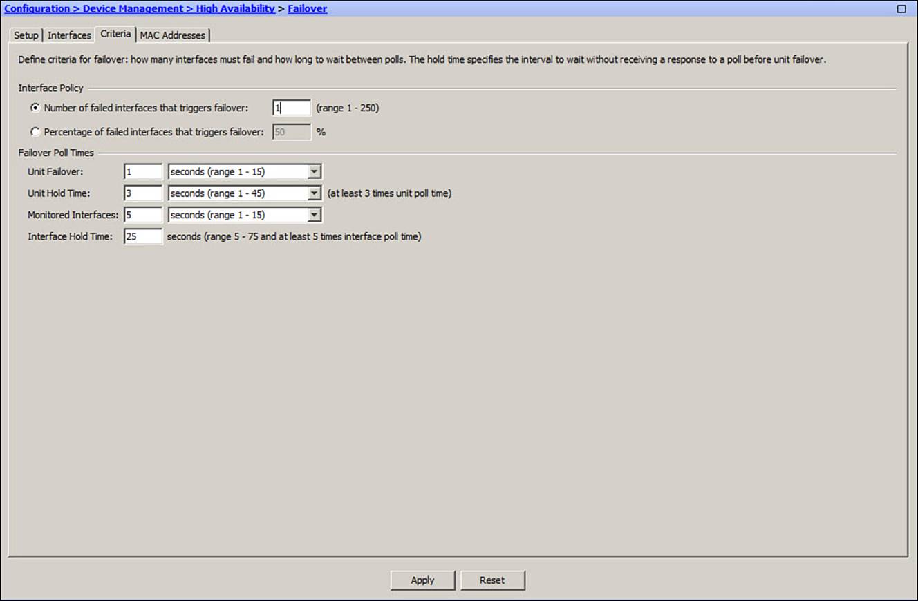
Figure 14-24. Configuring Failover Timer and Health Criteria
Configuring Failover Health Monitoring
By default, if an ASA tests and finds that at least one of its monitored interfaces has failed, it declares itself failed. In that case, if the ASA was in active mode, the other unit takes over the active role.
In active-standby mode, you can set the interface failure threshold with the following command:
ciscoasa(config)# failover interface-policy number[%]
Enter a specific number of failed interfaces as number or as a percentage of the total number of interfaces by adding the percent sign.
For active-active mode, you can use a similar command syntax in a failover group configuration in the system execution space. Use the following commands:
ciscoasa(config)# failover group {1 | 2}
ciscoasa(config-fover-group)# interface-policy number[%]
In ASDM, you can adjust the failover timers under the Criteria tab, as shown in the upper portion of Figure 14-23.
Detecting Asymmetric Routing
When two ASAs are configured as an active-active failover pair, traffic normally flows through one unit or the other for any given security context. After all, one unit is always active for a context while the other unit has the standby role. In some scenarios, however, two contexts might be configured to connect to the same network—effectively providing two active firewalls that can share or load balance the traffic load. The two contexts might be connected to different Internet service providers, yet connect to the same broad Internet on the outside, public network.
Although such scenarios are possible, they can be difficult to configure correctly. For example, outbound traffic can be handled by either of the two active contexts, but return traffic must come back through the same context that handled the connection originally. Otherwise, one context will build state information about the connection, while the other context will have no knowledge of it and will drop the return traffic.
This means that the upstream routers that connect the two contexts must be able to forward the return traffic to the appropriate ASA, to keep all packets belonging to the same traffic flow passing through the same firewall. This might require policy-based routing or a load-balancing function on the routers.
Sometimes, packets might exit one ASA, but the return traffic arrives on the other ASA. This is called asymmetric routing (ASR) and is shown in Figure 14-25. The ASA pair cannot prevent this from happening, but it can attempt to correct the mistake and keep related traffic flows that share the same source and destination address pairs together.
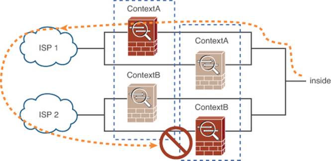
Figure 14-25. Asymmetric Routing
On ASA interfaces where asymmetric routing might be likely, you can configure the context interfaces into an ASR group. If a packet arrives on a grouped interface, the ASA will check for existing connection state information. If none is found, the ASA will check for other interfaces in the ASR group—even if they are located on the other active-active failover peer. If nothing is still found, the packet is dropped.
However, if connection state information is found on another interface in the group, the ASA will rewrite the Layer 2 header information and will resend the packet so that it is redirected to the correct interface, where it can be processed successfully. Packets will continue to be redirected as long as the traffic flow continues.
ASR groups require three features as prerequisites:
• Active-active failover
• Stateful failover between peers
• HTTP connection replication using the replication http command
To configure an ASR group, you must visit a specific context and configure the appropriate interface there. Interfaces in the same ASR group should be configured with the same group number, using the following commands:
ciscoasa/context(config)# interface phys_interface
ciscoasa/context(config-if)# asr-group number
In Examples 14-8 and 14-9, the outside interfaces in contexts ContextA and ContextB are assigned to the same ASR group, respectively.
Example 14-8. Configuring the ContextA Outside Interface for ASR Group 1
ciscoasa/ContextA(config)# interface ethernet0/0
ciscoasa/ContextA(config-if)# nameif outside
ciscoasa/ContextA(config-if)# security-level 0
ciscoasa/ContextA(config-if)# ip address 209.165.201.2 255.255.255.0 standby
209.165.201.3
ciscoasa/ContextA(config-if)# asr-group 1
Example 14-9. Configuring the ContextB Outside Interface for ASR Group 1
ciscoasa/ContextB(config)# interface ethernet0/0
ciscoasa/ContextB(config-if)# nameif outside
ciscoasa/ContextB(config-if)# security-level 0
ciscoasa/ContextB(config-if)# ip address 209.165.202.130 255.255.255.0 standby
209.165.202.131
ciscoasa/ContextB(config-if)# asr-group 1
Administering Failover
Sometimes, you might be connected to the active failover unit and find that you need to do something on the other failover unit. Rather than opening a new connection to the other unit, you can execute a command remotely on a failover peer.
Use the following command to send a command string to the appropriate failover unit and execute it there:
ciscoasa# failover exec {active | standby | mate} command_string
You can use the active keyword to execute the command string on the currently active unit, the passive keyword to execute on the currently passive unit, or the mate keyword to execute the command on the mate or peer unit, regardless of its current role.
As an example, suppose you are currently connected to the active unit. You can easily use the show version | include Serial command to display the unit’s serial number. You can use the failover exec command to run the same command on the failover peer remotely to get its serial number, as shown in Example 14-10.
Example 14-10. Remotely Executing the show version Command on a Failover Peer
ciscoasa# show version | include Serial
Serial Number: JMX1114L158
ciscoasa# failover exec mate show version | include Serial
Serial Number: JMX1114L14Z
ciscoasa#
Failover peers normally change their roles automatically, as failures are detected. In some cases, you might need to manually intervene to force a role change, so that you can take a unit out of service, upgrade the software, and so on. Use the failover active command to force the active role, or add the no keyword to force the standby role, as follows:
ciscoasa# [no] failover active
Verifying Failover Operation
Once you configure an ASA pair for failover operation, you can use the show failover command to verify the current status. The command output shows useful information like the failover timer values, operating system versions, the timestamp of the last failover event, the current peer roles, and the status of all monitored interfaces. Example 14-11 shows example output on an active-standby failover pair.
Example 14-11. Sample Output of the show failover Command in Active-Standby Mode
ciscoasa# show failover
Failover On
Failover unit Primary
Failover LAN Interface: LANfo Ethernet0/2 (up)
Unit Poll frequency 1 seconds, holdtime 3 seconds
Interface Poll frequency 5 seconds, holdtime 25 seconds
Interface Policy 1
Monitored Interfaces 2 of 110 maximum
failover replication http
Version: Ours 8.2(3), Mate 8.2(3)
Last Failover at: 03:25:39 UTC Apr 9 2011
This host: Primary - Active
Active time: 145986 (sec)
slot 0: ASA5510 hw/sw rev (2.0/8.2(3)) status (Up Sys)
Interface outside (209.165.200.226): Normal
Interface inside (192.168.1.10): Normal
Interface management (192.168.5.1): Normal (Not-Monitored)
slot 1: empty
Other host: Secondary - Standby Ready
Active time: 0 (sec)
slot 0: ASA5510 hw/sw rev (2.0/8.2(3)) status (Up Sys)
Interface outside (209.165.200.227): Normal
Interface inside (192.168.1.11): Normal
Interface management (192.168.5.2): Normal (Not-Monitored)
slot 1: empty
Stateful Failover Logical Update Statistics
Link : stateful Ethernet0/3 (up)
Stateful Obj xmit xerr rcv rerr
General 2262311522 0 117471377 0
sys cmd 13406589 0 13406554 0
up time 0 0 0 0
RPC services 18924 0 26 0
TCP conn 1953115393 0 91774144 0
UDP conn 200649501 0 12117485 0
ARP tbl 95121115 0 173168 0
Xlate_Timeout 0 0 0 0
IPv6 ND tbl 0 0 0 0
VPN IKE upd 0 0 0 0
VPN IPSEC upd 0 0 0 0
VPN CTCP upd 0 0 0 0
VPN SDI upd 0 0 0 0
VPN DHCP upd 0 0 0 0
SIP Session 0 0 0 0
Logical Update Queue Information
Cur Max Total
Recv Q: 0 8 110944928
Xmit Q: 0 23 108546628
ciscoasa#
Example 14-12 shows example output from the show failover command for an active-active failover pair. The output is similar to that of active-standby mode, but contains useful information about the current failover role for each failover group.
Example 14-12. Sample Output of the show failover Command in Active-Active Mode
ciscoasa# show failover
Failover On
Failover unit Primary
Failover LAN Interface: LANfo Ethernet0/2 (up)
Unit Poll frequency 1 seconds, holdtime 3 seconds
Interface Poll frequency 5 seconds, holdtime 25 seconds
Interface Policy 1
Monitored Interfaces 0 of 110 maximum
failover replication http
Version: Ours 8.2(3), Mate 8.2(3)
Group 1 last failover at: 02:00:24 UTC Apr 11 2011
Group 2 last failover at: 02:16:40 UTC Apr 11 2011
This host: Primary
Group 1 State: Active
Active time: 48024 (sec)
Group 2 State: Standby Ready
Active time: 626 (sec)
[output truncated for clarity]
Other host: Secondary
Group 1 State: Standby Ready
Active time: 0 (sec)
Group 2 State: Active
Active time: 47401 (sec)
[output truncated for clarity]
Finally, you can use the show failover history command to display a running record of failover activity. This output can be useful if you need to see how a failover event unfolded or evidence of a chain of failure events. Example 14-13 lists some sample output.
Example 14-13. Sample Output from the show failover history Command
ciscoasa# show failover history
==============================================================================
Group From State To State Reason
==============================================================================
02:00:24 UTC Apr 11 2011
2 Active Config Applied Active No Active unit found
02:10:32 UTC Apr 11 2011
2 Active Standby Ready Other unit wants me Standby
02:16:21 UTC Apr 11 2011
2 Standby Ready Just Active Set by the config command
02:16:21 UTC Apr 11 2011
2 Just Active Active Drain Set by the config command
02:16:21 UTC Apr 11 2011
2 Active Drain Active Applying Config Set by the config command
Leveraging Failover for a Zero Downtime Upgrade
Upgrading the operating system on a single standalone ASA is straightforward:
Step 1. Download a new image to the firewall.
Step 2. Save the running configuration.
Step 3. Reload the ASA.
Obviously, this should all be done during a scheduled maintenance time in your network, because the reload will interrupt network connectivity for a relatively long time.
A failover pair of ASAs can provide high availability even during a software upgrade by providing a “hitless upgrade” or “zero downtime upgrade.” The ASAs can be upgraded one at a time, and the failover function will maintain seamless operation even while the two units are running different releases of the software image. However, a zero downtime upgrade is possible only in the following scenarios:
• Upgrade from one maintenance release to another, such as from 8.3(1) to 8.3(4)
• Upgrade from one minor release to the next minor release increment, such as from 8.2(1) to 8.3(1)
• Upgrade from the last minor release of one major release to the first minor release of the next major release, such as from 8.4(7) to 9.0(1)
You can perform a zero downtime upgrade on a failover pair that is in either the active-standby or active-active mode. Although there are six steps to remember, they are all performed from the primary or active unit.
In a nutshell, the idea is to juggle the active and standby roles so that the standby unit is always the one being upgraded. Whichever unit has the active role at any time will always have the newer, upgraded image, and will continue to forward traffic and maintain all the state information. You should carefully follow these steps for a zero downtime upgrade:
Step 1. Download a new software image to both ASA devices.
Step 2. Use the boot system command to specify the new image file, and then save the running configuration.
Step 3. From the active unit, force the standby unit to reload by entering the failover reload-standby command, and then wait for it to finish booting completely.
Step 4. Force the active unit into the standby role by entering the no failover active command.
Step 5. Reload the former active unit by entering the reload command.
Step 6. Restore the former active unit to the active role by entering the failover active command.
Exam Preparation Tasks
As mentioned in the section, “How to Use This Book,” in the Introduction, you have a couple of choices for exam preparation: the exercises here, Chapter 17, “Final Preparation,” and the exam simulation questions on the CD-ROM.
Review All Key Topics
Review the most important topics in this chapter, noted with the Key Topic icon in the outer margin of the page. Table 14-4 lists a reference of these key topics and the page numbers on which each is found.
Table 14-4. Key Topics for Chapter 14

Define Key Terms
Define the following key terms from this chapter and check your answers in the glossary:
active-standby failover
active-active failover
LAN failover interface
stateless failover
stateful failover
failover group
asymmetric routing
zero downtime upgrade
Command Reference to Check Your Memory
This section includes the most important configuration and EXEC commands covered in this chapter. It might not be necessary to memorize the complete syntax of every command, but you should be able to remember the basic keywords that are needed.
To test your memory of the commands, cover the right side of Tables 14-5 through 14-7 with a piece of paper, read the description on the left side, and then see how much of the command you can remember.
Table 14-5. Commands Used for Active-Standby Failover Mode
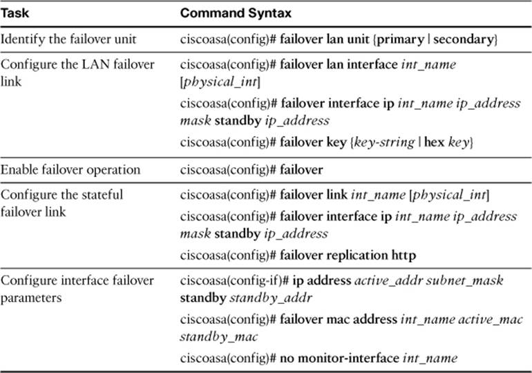
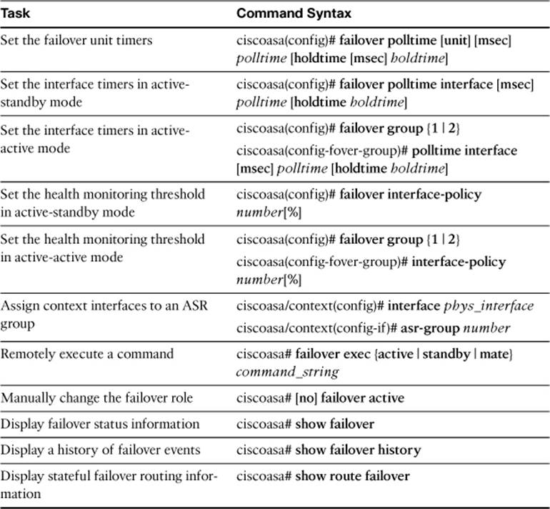
Table 14-6. Commands Used for Active-Active Failover Mode
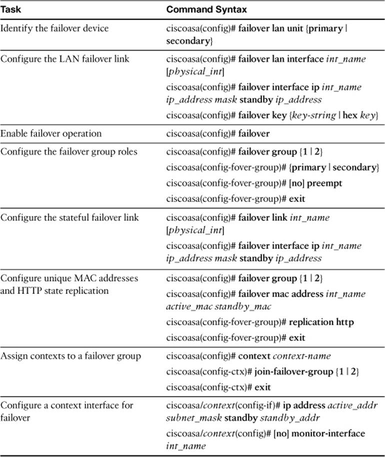
Table 14-7. Commands Used to Tune Failover Operation
The FIREWALL exam focuses on practical, hands-on skills that are used by a networking professional. Therefore, you should be able to identify the commands needed to configure and test an ASA feature.
All materials on the site are licensed Creative Commons Attribution-Sharealike 3.0 Unported CC BY-SA 3.0 & GNU Free Documentation License (GFDL)
If you are the copyright holder of any material contained on our site and intend to remove it, please contact our site administrator for approval.
© 2016-2026 All site design rights belong to S.Y.A.