CCNP Security FIREWALL 642-618 Official Cert Guide (2012)
Chapter 3. Configuring ASA Interfaces
This chapter covers the following topics:
• Configuring Physical Interfaces: This section discusses Cisco ASA interfaces that can be connected to a network through physical cabling, as well as the parameters that determine how the interfaces will operate.
• Configuring VLAN Interfaces: This section covers logical interfaces that can be used to connect an ASA to VLANs over a trunk link.
• Configuring Interface Security Parameters: This section explains the parameters you can set to assign a name, an IP address, and a security level to an ASA interface.
• Configuring the Interface MTU: This section discusses the maximum transmission unit size and how it can be adjusted to set the largest possible Ethernet frame that can be transmitted on an Ethernet-based ASA interface.
• Verifying Interface Operation: This section covers the commands you can use to display information about ASA interfaces and confirm whether they are operating as expected.
A Cisco Adaptive Security Appliance (ASA) must be configured with enough information to begin accepting and forwarding traffic before it can begin doing its job of securing networks. Each of its interfaces must be configured to interoperate with other network equipment and to participate in the IP protocol suite. This chapter discusses each of these topics in detail.
“Do I Know This Already?” Quiz
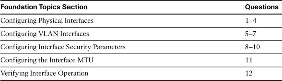
The “Do I Know This Already?” quiz allows you to assess whether you should read this entire chapter thoroughly or jump to the “Exam Preparation Tasks” section. If you are in doubt about your answers to these questions or your own assessment of your knowledge of the topics, read the entire chapter. Table 3-1 lists the major headings in this chapter and their corresponding “Do I Know This Already?” quiz questions. You can find the answers in Appendix A, “Answers to the ‘Do I Know This Already?’ Quizzes.”
Table 3-1. “Do I Know This Already?” Section-to-Question Mapping
Caution
The goal of self-assessment is to gauge your mastery of the topics in this chapter. If you do not know the answer to a question or are only partially sure of the answer, you should mark this question wrong for purposes of the self-assessment. Giving yourself credit for an answer you correctly guess skews your self-assessment results and might provide you with a false sense of security.
1. Which of the following answers describe an attribute of a redundant interface? (Choose all that apply.)
a. A redundant interface load balances traffic across member interfaces.
b. A redundant interface is made up of two or more physical interfaces.
c. An ASA can have up to eight redundant interface pairs.
d. Each member interface of a redundant interface cannot have its own security level.
e. IP addresses must be applied to the member physical interfaces of a redundant interface.
f. The member interfaces swap the active role when one of them fails.
2. What must happen for a member interface to take over the active role as part of a redundant interface?
a. Three hello messages must be missed.
b. The link status of the current active interface goes down.
c. A member interface, which was previously active before it went down, regains its link status.
d. Its member priority is higher than other member interfaces.
e. A timer must expire.
3. Which ASA command can be used to display a list of all physical interfaces?
a. show interfaces physical
b. show interface list
c. show hardware
d. show version
e. show ports
f. show
4. Suppose you want to double the bandwidth between an ASA’s outside interface and a neighboring switch. A single GigabitEthernet link exists today; a second link would also add redundancy. Which one of the following describes the best approach to meet the requirements?
a. Bring up a second GigabitEthernet interface on the same VLAN as the first one.
b. Configure the two interfaces as a redundant interface.
c. Configure the two interfaces as an EtherChannel.
d. Dual links are not possible on an ASA.
5. You have been assigned the task of configuring a VLAN interface on an ASA 5510. The interface will use VLAN 50. Which one of the following sets of commands should be entered first to accomplish the task?
a. interface vlan 50
no shutdown
b. interface ethernet0/0
no shutdown
c. interface ethernet0/0.5
vlan 50
no shutdown
d. interface ethernet0/0.50
no shutdown
6. Which of the following are correct attributes of an ASA interface that is configured to support VLAN interfaces? (Choose all that apply.)
a. The physical interface operates as an ISL trunk.
b. The physical interface operates as an 802.1Q trunk.
c. The subinterface numbers of the physical interface must match the VLAN number.
d. All packets sent from a subinterface are tagged for the trunk link.
e. An ASA can negotiate a trunk link with a connected switch.
7. Which one of the following answers contains the commands that should be entered on an ASA 5505 to create an interface for VLAN 6?
a. interface vlan 6
b. vlan 6
c. interface ethernet0/0.6
d. interface ethernet0/0.6
8. Which of the following represent security attributes that must be assigned to an active ASA interface when the ASA is in routed firewall mode? (Choose three answers.)
a. IP address
b. Access list
c. Interface name
d. Security level
e. Interface priority
f. MAC address
9. Which one of the following interfaces should normally be assigned a security level value of 100?
a. outside
b. dmz
c. inside
d. None of these answers are correct.
10. An ASA has two active interfaces, one with security level 0 and one with security level 100. Which one of the following statements is true?
a. Traffic is permitted to be initiated from security level 0 toward security level 100.
b. Traffic is permitted to be initiated from security level 100 toward security level 0.
c. Traffic is not permitted in either direction.
d. The interfaces must have the same security level by default before traffic can flow.
11. Suppose you are asked to adjust the MTU on the “inside” ASA interface Ethernet0/1 to 1460 bytes. Which one of the following answers contains the correct command(s) to enter?
a. ciscoasa(config)# mtu 1460
b. ciscoasa(config)# mtu inside 1460
c. ciscoasa(config)# interface ethernet0/1
ciscoasa(config-if)# mtu 1460
d. None of these answers are correct; the MTU must be greater than 1500.
12. From the following output, which of the following statements are true about ASA interface Ethernet0/2? (Choose all that apply.)
ciscoasa# show nameif
Interface Name Security
Ethernet0/0 outside 0
Ethernet0/1 inside 100
Management0/0 management 100
ciscoasa#
ciscoasa# show interface ethernet0/2
Interface Ethernet0/2 "", is administratively down, line protocol is down
Hardware is i82546GB rev03, BW 100 Mbps, DLY 100 usec
Auto-Duplex, Auto-Speed
Input flow control is unsupported, output flow control is unsupported
Available but not configured via nameif
MAC address 001a.a22d.1dde, MTU not set
IP address 10.1.1.1, subnet mask 255.255.255.0
0 packets input, 0 bytes, 0 no buffer
Received 0 broadcasts, 0 runts, 0 giants
0 input errors, 0 CRC, 0 frame, 0 overrun, 0 ignored, 0 abort
0 pause input, 0 resume input
0 L2 decode drops
0 packets output, 0 bytes, 0 underruns
0 pause output, 0 resume output
0 output errors, 0 collisions, 1 interface resets
0 late collisions, 0 deferred
0 input reset drops, 0 output reset drops, 0 tx hangs
input queue (blocks free curr/low): hardware (255/255)
output queue (blocks free curr/low): hardware (255/255)
ciscoasa#
a. The interface is configured and is live on the network.
b. The interface is not ready to use; the no shutdown command has not been issued.
c. The interface is not ready to use; it doesn’t have an IP address configured.
d. The interface is not ready to use; it doesn’t have a MAC address configured.
e. The interface is not ready to use; it doesn’t have a security level configured.
f. The interface is not ready to use; it doesn’t have an interface name configured.
Answer E might also be true, but you cannot confirm that a security level has been configured from the command output given. Because an interface name has not been configured with the nameif command, neither the interface name nor the security level is shown in the output.
Foundation Topics
Every ASA has one or more interfaces that can be used to connect to some other part of the network so that traffic can be inspected and controlled. ASA interfaces can be physical, where actual network media cables connect, or logical, where the interfaces exist internally and are passed to the network over a physical link. In this chapter, you learn how to configure both types of interfaces for connectivity and IP addressing.
In addition, to pass and inspect traffic, each interface must be configured with the following three security attributes:
• Interface name
• IP address and subnet mask
• Security level
You learn how to configure the security parameters in the section, “Configuring Interface Security Parameters.”
Configuring Physical Interfaces
An ASA supports multiple physical interfaces that can be connected into the network or to individual devices. From the Configuration tab in Cisco ASDM, you can view the list of interfaces by selecting Device Setup > Interfaces, as shown in Figure 3-1.
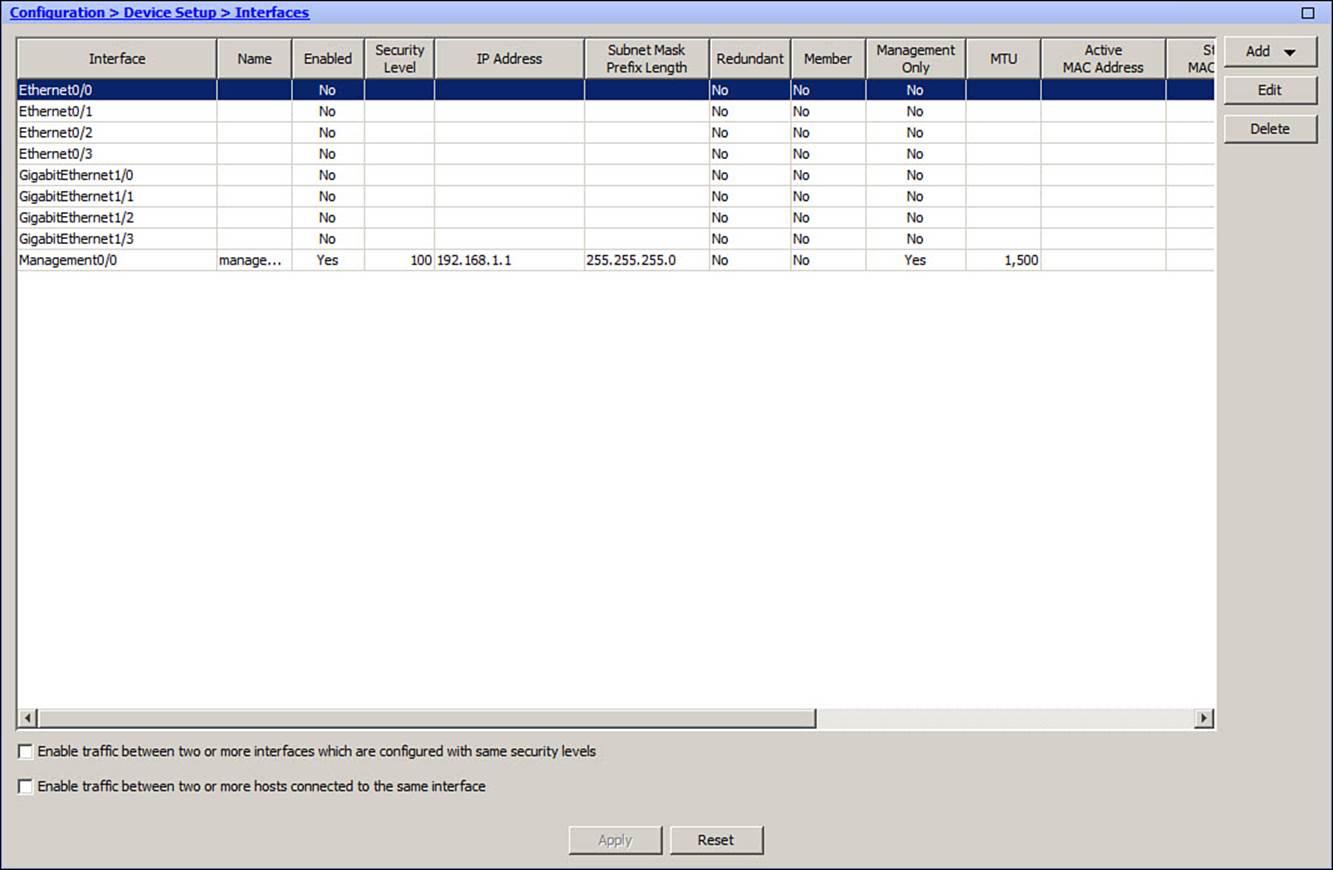
Figure 3-1. Using ASDM to View a List of Interfaces
From the CLI, you can see a list of the physical firewall interfaces that are available by using the following command:
ciscoasa# show version
Firewall interfaces are referenced by their hardware index and their physical interface names. Example 3-1 lists the physical interfaces in an ASA 5510. Ethernet0/0 through 0/3 and Management0/0 are built-in interfaces, while GigabitEthernet1/0 through 1/3 are installed as a 4GE-SSM module.
Example 3-1. Listing Physical ASA Interfaces
ciscoasa# show version
Cisco Adaptive Security Appliance Software Version 8.2(3)
Device Manager Version 6.3(4)
Compiled on Fri 06-Aug-10 07:51 by builders
System image file is "disk0:/asa823-k8.bin"
Config file at boot was "startup-config"
ciscoasa up 1 day 10 hours
Hardware: ASA5510-K8, 256 MB RAM, CPU Pentium 4 Celeron 1600 MHz
Internal ATA Compact Flash, 256MB
BIOS Flash M50FW080 @ 0xffe00000, 1024KB
Encryption hardware device : Cisco ASA-55x0 on-board accelerator (revision 0x0)
Boot microcode : CN1000-MC-BOOT-2.00
SSL/IKE microcode: CNLite-MC-SSLm-PLUS-2.03
IPSec microcode : CNlite-MC-IPSECm-MAIN-2.04
0: Ext: Ethernet0/0 : address is 001a.a22d.1ddc, irq 9
1: Ext: Ethernet0/1 : address is 001a.a22d.1ddd, irq 9
2: Ext: Ethernet0/2 : address is 001a.a22d.1dde, irq 9
3: Ext: Ethernet0/3 : address is 001a.a22d.1ddf, irq 9
4: Ext: Management0/0 : address is 001a.a22d.1ddb, irq 11
5: Int: Internal-Data0/0 : address is 0000.0001.0002, irq 11
6: Int: Not used : irq 5
7: Ext: GigabitEthernet1/0 : address is 001a.a22d.20f1, irq 255
8: Ext: GigabitEthernet1/1 : address is 001a.a22d.20f2, irq 255
9: Ext: GigabitEthernet1/2 : address is 001a.a22d.20f3, irq 255
10: Ext: GigabitEthernet1/3 : address is 001a.a22d.20f4, irq 255
11: Int: Internal-Data1/0 : address is 0000.0003.0002, irq 255
Licensed features for this platform:
Maximum Physical Interfaces : Unlimited
Maximum VLANs : 100
Inside Hosts : Unlimited
Failover : Active/Active
VPN-DES : Enabled
[output truncated for clarity]
Before you begin configuring the ASA interfaces, you should first use the interface list to identify each of the interfaces you will use. At a minimum, you need one interface as the “inside” of the ASA and one as the “outside.”
Default Interface Configuration
Some interfaces come predefined in the initial factory default configuration. You can view the interface mappings with the show nameif EXEC command. As shown in Example 3-2, an ASA 5510 or higher model defines only one interface, Management0/0, for use by default. The interface is named “management” and is set aside for out-of-band management access.
Example 3-2. Default Interface Configuration on ASA 5510 and Higher Models
ciscoasa# show nameif
Interface Name Security
Management0/0 management 100
ciscoasa#
An ASA 5505 takes a different approach with its default interfaces, as shown in Example 3-3. Rather than use physical interfaces, it defines an “inside” and an “outside” interface using two logical VLANs: VLAN 1 and VLAN 2.
Example 3-3. Default Interface Configuration on the ASA 5505
ciscoasa# show nameif
Interface Name Security
Vlan1 inside 100
Vlan2 outside 0
ciscoasa#
These two VLANs are then applied to the physical interfaces such that interface Ethernet0/0 is mapped to VLAN 2, while Ethernet0/1 through 0/7 are mapped to VLAN 1 (inside). This configuration gives one outside interface that can be connected to a service provider network for an Internet connection. The remaining seven inside interfaces can be connected to individual devices on the protected network.
You can display the ASA 5505 interface-to-VLAN mapping by entering the show switch vlan command, as shown in Example 3-4.
Example 3-4. Displaying the ASA 5505 Interface-to-VLAN Mapping
ciscoasa# show switch vlan
VLAN Name Status Ports
---- -------------------------------- --------- -----------------------------
1 inside up Et0/1, Et0/2, Et0/3, Et0/4
Et0/5, Et0/6, Et0/7
2 outside up Et0/0
ciscoasa#
Configuring Physical Interface Parameters

For each physical interface, you can configure the speed, duplex, and the interface state. In ASDM, select Configuration > Interfaces, select an interface, and click the Edit button. In the General tab, click Configure Hardware Properties, as shown in Figure 3-2.
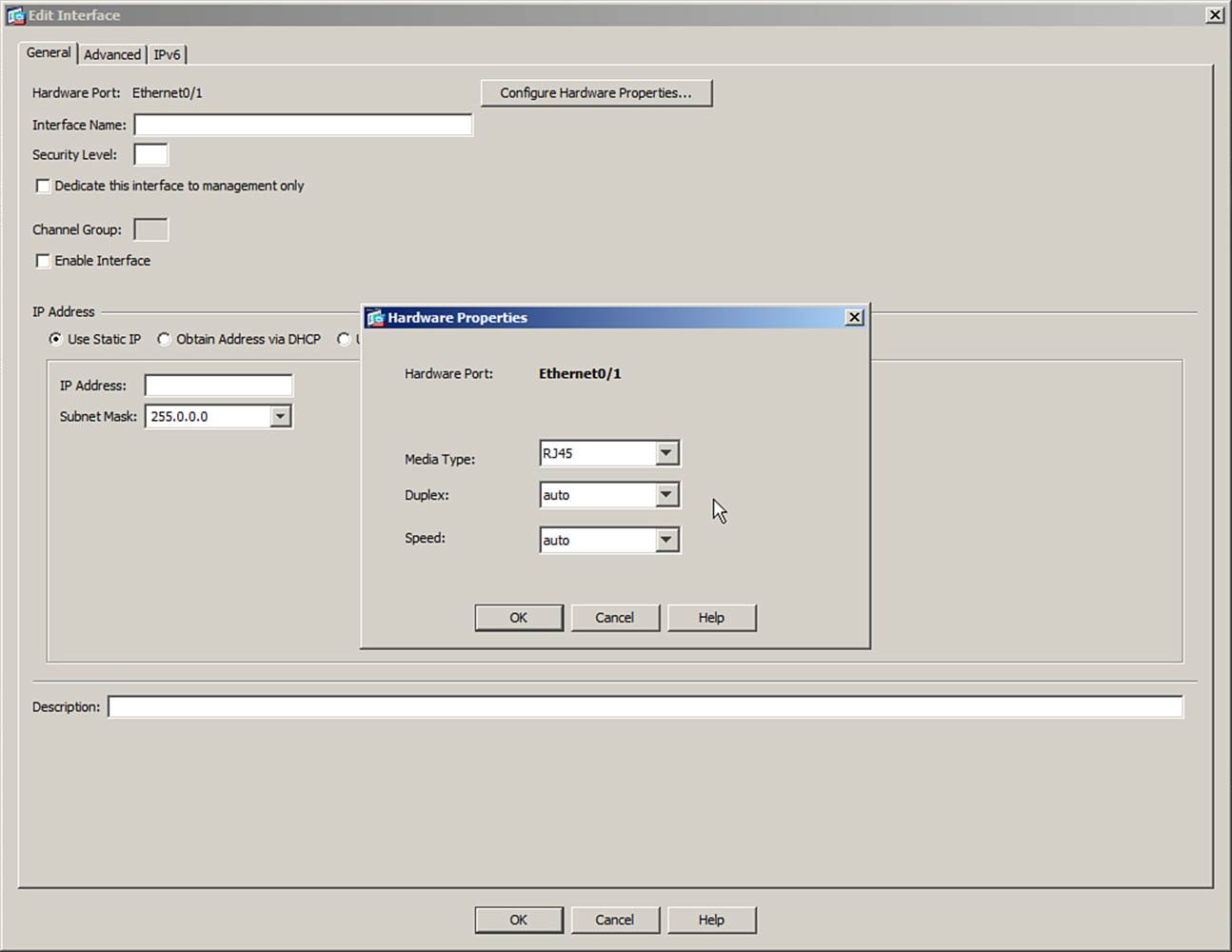
Figure 3-2. Configuring Physical Interface Parameters in ASDM
You can do the same task from the CLI by using the following commands:
ciscoasa(config)# interface hardware-id
ciscoasa(config-if)# speed {auto | 10 | 100 | 1000}
ciscoasa(config-if)# duplex {auto | full | half}
ciscoasa(config-if)# [no] shutdown
By default, an interface uses autodetected speed and autonegotiated duplex mode, as if the speed auto and duplex auto commands had been entered. As long as the ASA interface and the device connected to it are configured the same, the interface will automatically come up using the maximum speed and full-duplex mode. You can also statically configure the interface speed to 10, 100, or 1000 Mbps, as wellas full or half duplex mode.
By default, physical interfaces are administratively shut down. Use the no shutdown interface configuration command to enable each one individually. As well, you can shut an interface back down with the shutdown command.
Note
Other parameters, such as the interface name, security level, and IP address, should be configured, too. These are discussed in the section, “Configuring Interface Security Parameters.”
Mapping ASA 5505 Interfaces to VLANs
By default, an ASA 5505 maps interface Ethernet0/0 to VLAN 2 and interfaces Ethernet0/1 through 0/7 to VLAN 1. All eight interfaces are connected to an internal 8-port switch, with each interface configured as an access link mapped to a single VLAN.
Figure 3-3 shows how ASDM can be used to map a physical interface to a different VLAN number. First, a new interface is created and named vlan 10. At the top of the Add Interface dialog box, Ethernet0/3 is added to the list of interfaces that are mapped to VLAN 10.
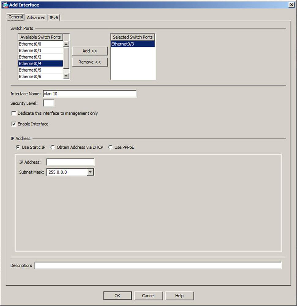
Figure 3-3. Mapping an ASA 5505 Interface to a VLAN
You can use the following CLI command to accomplish the same task:
ciscoasa(config-if)# switchport access vlan vlan-id
The vlan-id parameter represents a VLAN interface that has already been created and configured. The section, “Configuring VLAN Interfaces,” covers this in detail.
In Example 3-5, interface Ethernet0/3 is mapped to VLAN 10, while Ethernet0/4 is mapped to VLAN 20.
Example 3-5. Mapping Interfaces to VLANs on an ASA 5505
ciscoasa(config)# interface ethernet0/3
ciscoasa(config-if)# switchport access vlan 10
ciscoasa(config-if)# interface ethernet0/4
ciscoasa(config-if)# switchport access vlan 20
Configuring Interface Redundancy
By default, each physical ASA interface operates independently of any other interface. The interface can be in one of two operating states: up or down. When an interface is down for some reason, the ASA cannot send or receive any data through it. For example, the switch port where an ASA interface connects might fail, causing the ASA interface to go down, too.
To keep an ASA interface up and active all the time, you can configure physical interfaces as redundant pairs. As a redundant pair, two interfaces are set aside for the same ASA function (inside, outside, and so on), and connect to the same network. Only one of the interfaces is active at any given time; the other interface stays in a standby state. As soon as the active interface loses its link status and goes down, the standby interface becomes active and takes over passing traffic.
Both physical interfaces in a redundant pair are configured as members of a single logical “redundant” interface. To join two interfaces as a redundant pair, the interfaces must be of the same type (10/100/1000BASE-TX, for example).
The redundant interface, rather than its physical member interfaces, is configured with a unique interface name, security level, and IP address—all the parameters used in ASA interface operations.
First, you must create the redundant interface by entering the following configuration command:
ciscoasa(config)# interface redundant number
You can define up to eight redundant interfaces on an ASA. Therefore, the interface number can be 1 through 8.
Next, use the following command to add a physical interface as a member of the redundant interface:
ciscoasa(config-int)# member-interface physical_interface
Here, physical_interface is the hardware name and number, like ethernet0/1 or gigabitethernet0/1, for example. In Figure 3-4, ASA interfaces Ethernet0/0 and Ethernet0/1 are member interfaces of a logical redundant interface called Redundant1, while Ethernet0/2 and Ethernet0/3 are members of interface Redundant2.
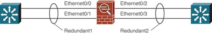
Figure 3-4. Example Redundant Interfaces
Be aware that the member interface cannot have a security level or an IP address configured. In fact, as soon as you enter the member-interface command, the ASA will automatically clear those parameters from the physical interface configuration. You should repeat this command to add a second physical interface to the redundant pair.
Keep in mind that the order in which you configure the interfaces is important. The first physical interface added to a logical redundant interface will become the active interface. That interface will stay active until it loses its link status, causing the second or standby interface to take over. The standby interface can also take over when the active interface is administratively shut down with the shutdown interface configuration command.
However, the active status will not revert to the failed interface, even when it comes back up. The two interfaces trade the active role back and forth only when one of them fails.
The redundant interface also takes on the MAC address of the first member interface that you configure. Regardless of which physical interface is active, that same MAC address will be used. You can override this behavior by manually configuring a unique MAC address on the redundant interface with the mac-address mac_address interface configuration command.
In Example 3-6, interfaces Ethernet0/0 and Ethernet0/1 are configured to be used as logical interface redundant 1.
Example 3-6. Configuring a Redundant Interface Pair
ciscoasa(config)# interface redundant 1
ciscoasa(config-if)# member-interface ethernet0/0
INFO: security-level and IP address are cleared on Ethernet0/0.
ciscoasa(config-if)# member-interface ethernet0/1
INFO: security-level and IP address are cleared on Ethernet0/1.
ciscoasa(config-if)# no shutdown
The redundant interface is now ready to be configured as a normal ASA interface. From this point on, you should not configure anything on the two physical interfaces other than the port speed and duplex.
Note
Make sure the logical redundant interface and the two physical interfaces are enabled with the no shutdown command. Even though they are all logically associated, they can be manually shut down or brought up independently.
To accomplish the same thing through ASDM, first select Add > Redundant Interface from the drop-down menu in the upper-right corner of the interface listing. A new Add Redundant Interface dialog box appears, as shown in Figure 3-5. Select the redundant interface number and the two physical interfaces that will operate as a redundant pair. To enable the new redundant interface for use, be sure to check the Enable Interface check box.
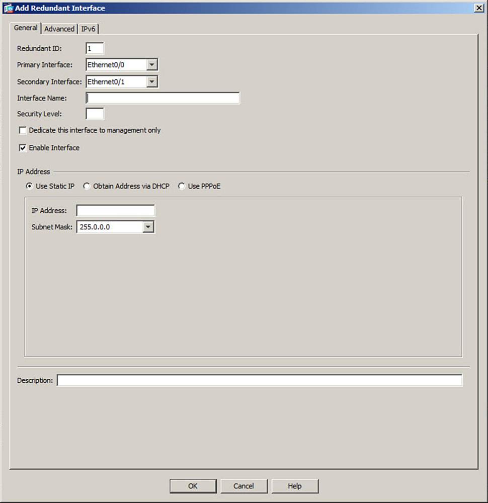
Figure 3-5. Adding a Redundant Interface in ASDM
Note
Other parameters, such as the interface name, security level, and IP address, should be configured, too. These are discussed in the section, “Configuring Interface Security Parameters.”
Configuring an EtherChannel
A single link between an ASA and a switch provides simple connectivity, but it is a single point of failure. If the link goes down, no data can travel across it. In the previous section, you learned that a redundant interface binds two physical interfaces into one logical interface. The possibility of a link failure is reduced, because one of the two interfaces will always be up and available; however, only one of the two links can pass data at any given time.
How can you maximize availability with more than one link, while leveraging the bandwidth of all of them at the same time? Beginning with ASA software release 8.4(1), you can use an EtherChannel to make that all possible. With an EtherChannel, two to eight active physical interfaces can be grouped or bundled together as a single logical port-channel interface. Each interface must be of the same type, speed, and duplex mode before an EtherChannel can be built.
Figure 3-6 shows an EtherChannel that is built out of multiple physical GigabitEthernet interfaces that connect an ASA to a Catalyst switch. On the ASA, the resulting logical interface is named interface port-channel 1. Notice that the individual links in the Ether-Channel can have different interface names on each end. The interfaces can also be connected and grouped in any arbitrary order. What matters is that the interfaces form one common EtherChannel link between the two devices.
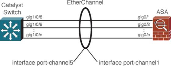
Figure 3-6. Building an EtherChannel from Multiple Physical Links
An ASA can support up to eight active interfaces in a single EtherChannel; however, you can configure up to 16 different interfaces per EtherChannel, although only eight of them can be active at any time. If one active interface fails, another one automatically takes its place. Although Figure 3-6 shows a single EtherChannel link, an ASA can support up to 48 different EtherChannels.
Because multiple interfaces are active in an EtherChannel, the available bandwidth can be scaled over that of a single interface. Traffic is load balanced by distributing the packets across the active interfaces. The ASA computes a hash value based on values found in the packet header, such as the source or destination MAC address, IP address, or the UDP or TCP port number. You can configure a preset combination of fields that are used. As long as the number of active interfaces is a multiple of two, the ASA can evenly distribute packets across them.
To build an EtherChannel, the ASA and the switch must both agree to do so. You can configure the ASA interfaces to statically participate, where the EtherChannel is “always on.” In that case, the switch interfaces must also be configured for “always on” operation. Instead, you can configure the ASA and switch to negotiate an EtherChannel with each other.
Negotiation uses the Link Aggregation Control Protocol (LACP), which is a standards-based protocol. LACP packets are exchanged between the ASA and the switch over the interfaces that can become part of an EtherChannel. The ASA and the switch use a system priority (a 2-byte priority value followed by a 6-byte switch MAC address) to decide which one is allowed to make decisions about what interfaces are actively participating in the EtherChannel at a given time.
Interfaces are selected and become active according to their port priority value (a 2-byte priority followed by a 2-byte port number), where a low value indicates a higher priority. A set of up to 16 potential links can be defined for each EtherChannel. Through LACP, up to eight of these having the lowest port priorities can become active EtherChannel links at any given time. The other links are placed in a standby state and will be enabled in the EtherChannel if one of the active links goes down.
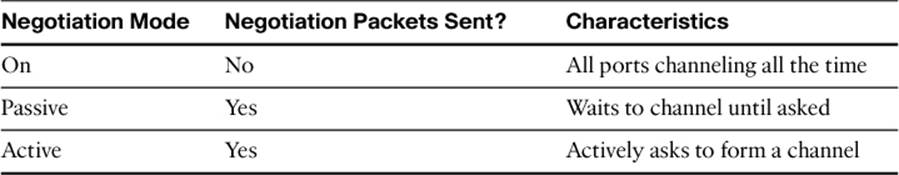
LACP can be configured in the active mode, in which the ASA actively asks a far-end switch to negotiate an EtherChannel, or in passive mode, in which the ASA negotiates an EtherChannel only if the far end initiates it. Table 3-2 summarizes the EtherChannel negotiation methods and characteristics.
Table 3-2. EtherChannel Negotiation Methods
To configure an EtherChannel in ASDM, begin by defining the port-channel interface. Select Configuration > Device Setup > Interfaces, click the Add button, and select
EtherChannel Interface. Under the General tab, enter an arbitrary Port Channel ID number (1 to 48) that will identify the port-channel interface.
Next, select an interface from the Available Physical Interface list and click the Add>> button to make it a member of the EtherChannel. You can repeat this process to add multiple interfaces. Make sure to select the Enable Interface check box to enable the port-channel interface for use. InFigure 3-7, interface port-channel1 has been created. Ethernet0/2 and Ethernet0/3 have been added as member interfaces.
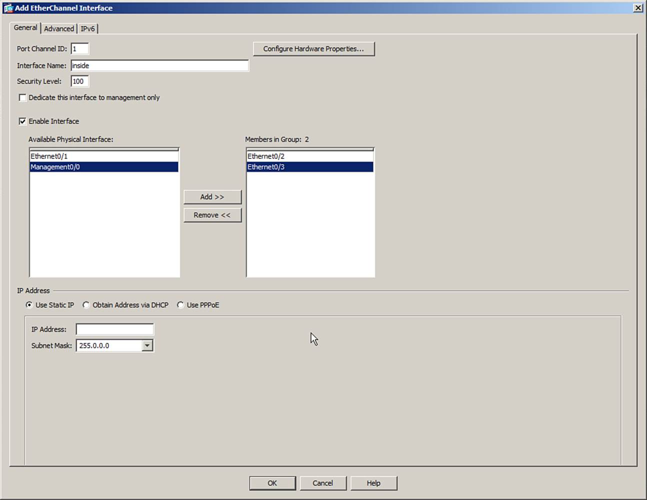
Figure 3-7. Configuring a New EtherChannel in ASDM
Note
Before an interface can be configured for an EtherChannel, it must not have a name configured. After the EtherChannel interfaces are configured, you can define a name and other security parameters on the port-channel interface.
Notice that Figure 3-7 also has fields for Interface Name, Security Level, and IP Address. These fields are not applied to the individual member interfaces; instead, they are applied to the port-channel interface. The fields are covered in the section, “Configuring Interface Security Parameters.”
Next, configure the method that the ASA will use to distribute packets across the links within the EtherChannel. By default, a packet’s source and destination IP addresses are used to compute a hash index that points to the link that will carry the packet. This is the appropriate choice in most cases, as long as the source and destination IP addresses are unique and diverse. The more varied the hash input values, the better the traffic will be distributed across the links in the EtherChannel.
In some scenarios, the majority of the traffic might travel between the same two IP addresses, causing most of the packets to travel over only one link of the EtherChannel. In that case, you can configure the EtherChannel load-balancing method to use additional information, such as a Layer 4 port number, MAC addresses, or a VLAN number, to provide more uniqueness so that the packets can be spread more evenly across the EtherChannel links. The possible load-balancing methods are as follows:
• Destination IP
• Destination IP and Layer 4 Port
• Destination MAC Address
• Destination Layer 4 Port
• Source and Destination IP Address
• Source and Destination MAC Address
• Source and Destination IP Address and Layer 4 Port
• Source and Destination Layer 4 Port
• Source IP Address
• Source IP Address and Layer 4 Port
• Source MAC Address
• Source Layer 4 Port
• VLAN Destination IP Address
• VLAN Destination IP and Layer 4 Port
• VLAN Only
• VLAN Source and Destination IP Address
• VLAN Source and Destination IP Address and Layer 4 Port
• VLAN Source IP Address
• VLAN Source IP Address and Layer 4 Port
To configure the load-balancing method, select the Advanced tab in the Add EtherChannel Interface screen and choose the method from the drop-down list at the bottom of the screen, as shown in Figure 3-8.
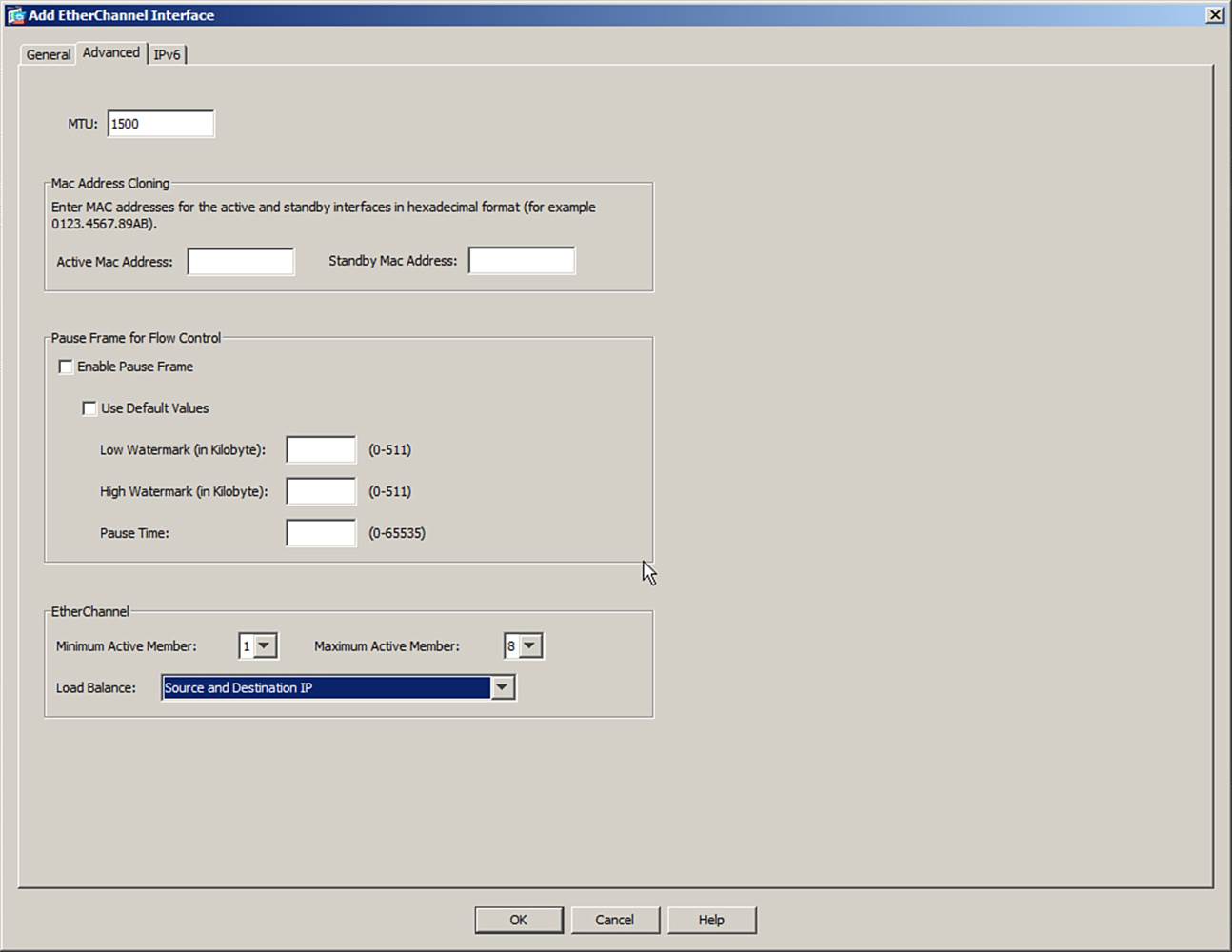
Figure 3-8. Configuring the EtherChannel Load-Balancing Method
Next, you need to configure a negotiation method for the EtherChannel. ASDM uses a default method of “active” on each member interface, where the ASA will use LACP to actively ask the far-end switch to bring up the EtherChannel. To configure the method, select Configuration > Device Setup > Interfaces, select an interface that is a member of the EtherChannel, and click the Edit button. In Figure 3-9, interfaces Ethernet0/2 and 0/3 are shown to be members of the Port-channel1 group. Because their individual configurations are restricted, they are shown with a lock icon next to their names. Remember that the security parameters of an EtherChannel are configured on the Port-channel interface instead.
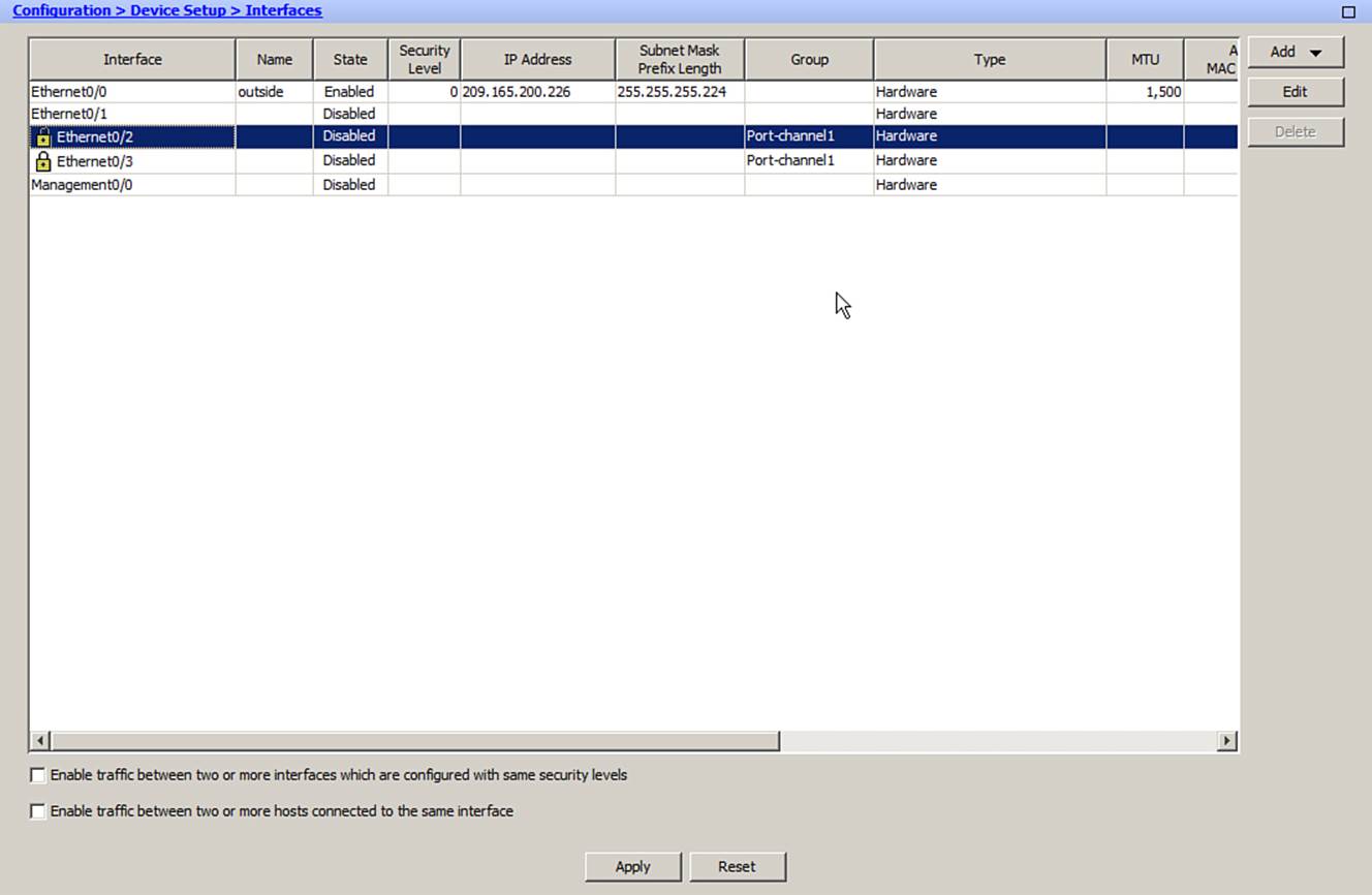
Figure 3-9. Selecting an EtherChannel Interface for Configuration
Under the General tab of the Edit Interface screen, make sure that the Enable Interface check box under the Channel Group is selected. Select the Advanced tab and use the EtherChannel drop-down menu to set the negotiation mode, which can be either Active, Passive, or On, as shown inFigure 3-10.
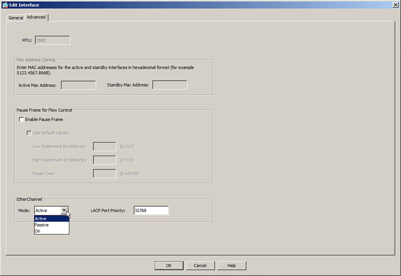
Figure 3-10. Configuring the EtherChannel Negotiation Method
You can configure more interfaces in the channel group number than are allowed to be active in the channel. This prepares extra standby interfaces to replace failed active ones. Set a lower LACP port priority (1 to 65,535; default 32,768) for any interfaces that must be active and a higher priority for interfaces that might be held in the standby state. Otherwise, just use the default scenario, in which all ports default to 32,768, and the lower port numbers (in interface number order) are used to select the active ports.
By default, an ASA uses LACP system priority of 32,768. If the ASA and the switch both use the same value, the one with the lower MAC address becomes the decision maker over the LACP negotiations. You can change the system priority by selecting Configuration > Device Setup > EtherChannel.
You can also configure an EtherChannel by using the CLI. Select a physical interface that will be a member of the EtherChannel, and then identify the port-channel number where it will belong, along with the negotiation method that will be used:
ciscoasa(config)# lacp system-priority priority
ciscoasa(config)# interface type mod/num
ciscoasa(config-if)# channel-protocol lacp
ciscoasa(config-if)# channel-group number mode {on | passive | active}
ciscoasa(config-if)# lacp port-priority priority
As an example of LACP configuration, suppose that you want to configure an ASA to actively negotiate an EtherChannel using interfaces Ethernet0/2 and 0/3. You can use the commands listed in Example 3-7 to accomplish this.
Example 3-7. Configuring an EtherChannel Using the CLI
CISCOASA(config)# interface ethernet0/2
CISCOASA(config-if)# channel-protocol lacp
CISCOASA(config-if)# channel-group 1 mode active
CISCOASA(config-if)# exit
CISCOASA(config)# interface ethernet0/3
CISCOASA(config-if)# channel-protocol lacp
CISCOASA(config-if)# channel-group 1 mode active
CISCOASA(config-if)# exit
If you find that an EtherChannel is having problems, remember that the entire concept is based on consistent configurations on both ends of the channel. You can verify the Ether-Channel state with the show port-channel summary command. Each port in the channel is shown, along with flags indicating the port’s state, as shown in Example 3-8.
Example 3-8. show port-channel summary Command Output
CISCOASA# show port-channel summary
Flags: D - down P - bundled in port-channel
I - stand-alone s - suspended
H - Hot-standby (LACP only)
U - in use N - not in use, no aggregation/nameif
M - not in use, no aggregation due to minimum links not met
w - waiting to be aggregated
Number of channel-groups in use: 1
Group Port-channel Protocol Ports
------+-------------+-----------+-----------------------------------------------
1 Po1(U) LACP Et0/2(P) Et0/3(P)
CISCOASA#
The status of the port channel shows the EtherChannel logical interface as a whole. This should show U (in use) if the channel is operational. You also can examine the status of each interface within the channel. Notice that both of the channel interfaces have flags (P), which indicate that they are active in the port-channel.
Configuring VLAN Interfaces
A physical ASA interface can be configured to connect to multiple logical networks. To do this, the interface is configured to operate as a VLAN trunk link. On ASA 5510 and higher platforms, each VLAN that is carried over the trunk link terminates on a unique subinterface of a physical interface. On an ASA 5505, each VLAN is defined by a unique VLAN interface and can connect to physical interfaces and be carried over a VLAN trunk link.
VLAN Interfaces and Trunks on ASA 5510 and Higher Platforms
An ASA trunk link supports only the IEEE 802.1Q trunk encapsulation method. As each packet is sent over a trunk link, it is tagged with its source VLAN number. As packets are removed from the trunk, the tag is examined and removed so that the packets can be forwarded to their appropriate VLANs. Figure 3-11 shows how a trunk link between an ASA and a switch can encapsulate or carry frames from multiple VLANs.
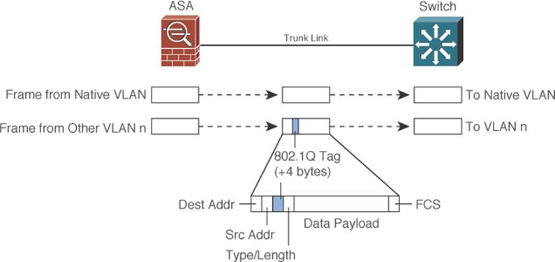
Figure 3-11. IEEE 802.1Q Trunk Link Operation with an ASA
IEEE 802.1Q trunk links support the concept of a native VLAN. Frames coming from the native VLAN are sent over the trunk link without a tag, while frames from other VLANs have a tag added while in the trunk. By default, only packets that are sent out the ASA’s physical interface itself are not tagged, and they appear to use the trunk’s native VLAN. Packets that are sent out a subinterface do receive a VLAN tag.
Note
Although a Cisco switch can be configured to negotiate the trunk status or encapsulation through the Dynamic Trunking Protocol (DTP), ASA platforms cannot. Therefore, an ASA trunk link is either on or off, according to the subinterface configuration. You should make sure that the switch port is configured to trunk unconditionally, too.
You can configure a trunk link by using the following configuration commands:
ciscoasa(config)# interface hardware_id.subinterface
ciscoasa(config-subif)# vlan vlan_id
First, use the interface command to identify the physical interface that will become a trunk link and the subinterface that will be associated with a VLAN number. The physical interface is given as hardware_id, such as Ethernet0/3, followed by a dot or period. A subinterface number is added to the physical interface name to create the logical VLAN interface. This is an arbitrary number that must be unique for each logical interface.
Use the vlan vlan_id subinterface configuration command to specify the VLAN number. The subinterface number does not have to match the VLAN number, although it can for convenience and readability.
As an example, Figure 3-12 shows a network diagram of a trunk link between an ASA and a switch. ASA physical interface Ethernet0/3 is used as the trunk link. VLAN 10 is carried over ASA subinterface Ethernet0/3.1, while VLAN 20 is carried over Ethernet0/3.2. The trunk link can be configured with the commands listed in Example 3-9.
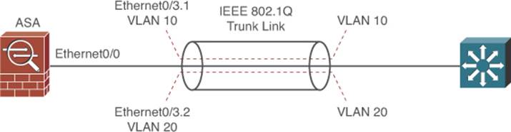
Figure 3-12. Network Diagram for Example 3-9 Trunk Link Configuration
Example 3-9. Configuring a Trunk Link on an ASA
ciscoasa(config)# interface ethernet0/3
ciscoasa(config-if)# no shutdown
ciscoasa(config-if)# interface ethernet0/3.1
ciscoasa(config-subif)# vlan 10
ciscoasa(config-subif)# no shutdown
ciscoasa(config-subif)# interface ethernet0/3.2
ciscoasa(config-subif)# vlan 20
ciscoasa(config-subif)# no shutdown
The same trunk link configuration can be accomplished with ASDM. Subinterfaces used in a trunk link must first be added or created. In the interface list view, select the Add > Interface function in the upper-right corner of the ASDM application. Select the hardware port or physical interface that will be used for the trunk link. In Figure 3-13, Ethernet0/3 is used. Because subinterface Ethernet0/3.1 is being created, the subinterface ID is set to 1. The VLAN ID is set to 10.
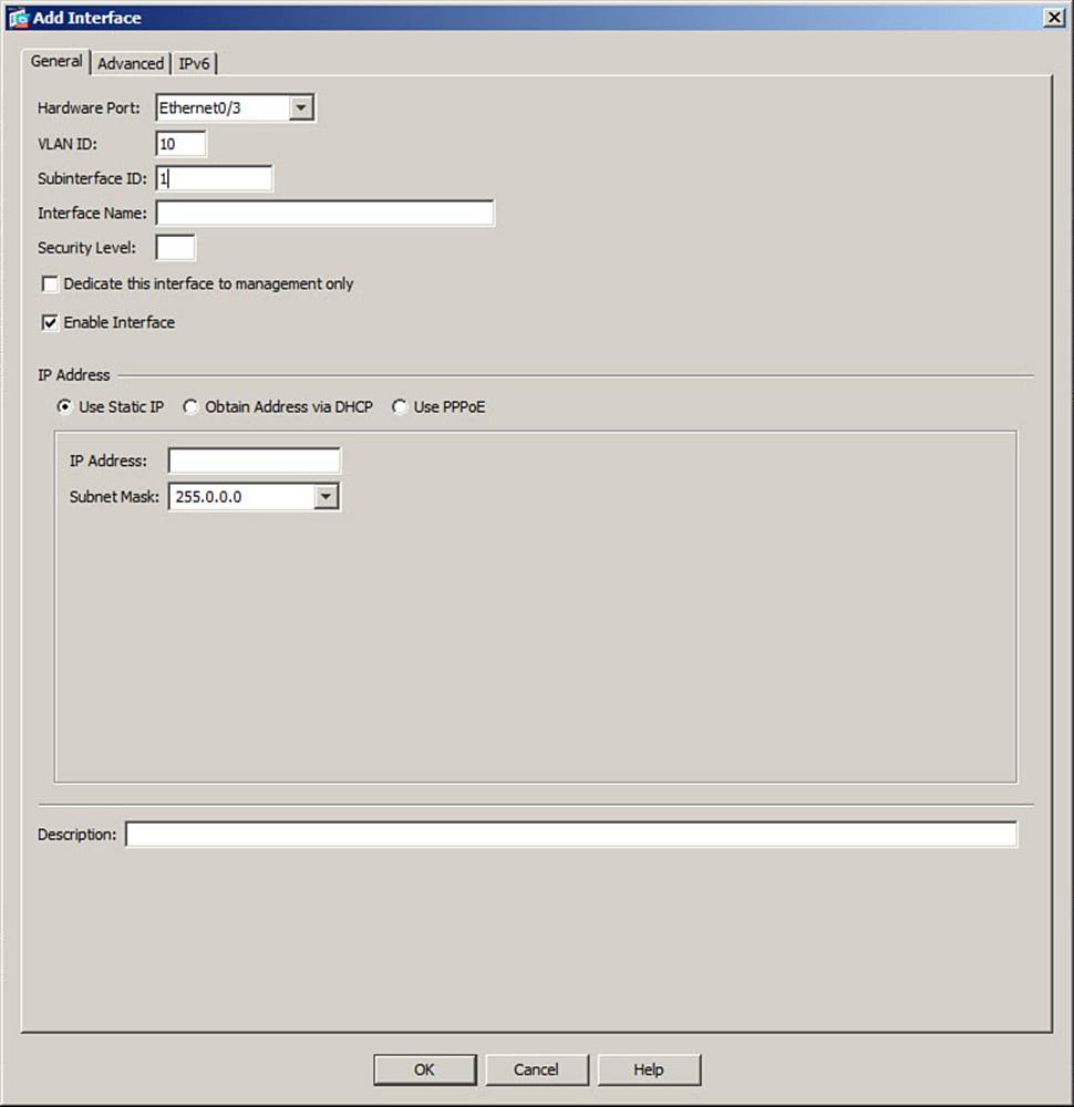
Figure 3-13. Configuring a Trunk Link in ASDM
Note
Other parameters, such as the interface name, security level, and IP address, should be configured, too. These are discussed in the section, “Configuring Interface Security Parameters.”
VLAN Interfaces and Trunks on an ASA 5505
On an ASA 5505, VLANs are supported on the physical interfaces, but only if corresponding logical VLAN interfaces are configured. For example, if VLAN 1 is to be used, the interface vlan 1 command must be entered to create the internal VLAN and the VLAN interface.
By default, the ASA 5505 platform includes the interface vlan 1 and interface vlan 2 commands in its configuration.
Other parameters, such as the interface name, security level, and IP address, should be configured on VLAN interfaces rather than on physical interfaces. These are discussed in the section, “Configuring Interface Security Parameters.”
If you need to carry multiple VLANs over a link to a neighboring switch, you can configure an ASA 5505 physical interface as a VLAN trunk link. First, create the individual VLANs with the interface vlan vlan-id configuration command. Then, configure the physical interface to operate in IEEE 802.1Q trunk mode and allow specific VLANs to be carried over it with the following interface configuration commands:
ciscoasa(config-if)# switchport mode trunk
ciscoasa(config-if)# switchport trunk allowed vlan vlan-list
By default, no VLANs are permitted to be carried over a trunk link. You must identify which VLANs can be carried by entering vlan-list, which is a comma-separated list of VLAN numbers. In Example 3-10, an ASA 5505 is configured to support VLANs 10 and 20 and carry those VLANs over interface Ethernet0/5, which is configured as a trunk link.
Example 3-10. ASA VLAN CLI Configuration
ciscoasa(config)# interface vlan 10
ciscoasa(config-if)# exit
ciscoasa(config)# interface vlan 20
ciscoasa(config-if)# exit
ciscoasa(config)# interface ethernet0/5
ciscoasa(config-if)# switchport mode trunk
ciscoasa(config-if)# switchport trunk allowed vlan 10,20
Configuring Interface Security Parameters
Once you identify an ASA interface that will be connected to the network, you will need to apply the following three security parameters to it:
• Interface name
• IP address
• Security level
These parameters are explained in the following sections.
Naming the Interface
ASA interfaces are known by two different names:
• Hardware name: Specifies the interface type, hardware module, and port number. The hardware names of physical interfaces can include Ethernet0/0, Management0/0, and GigabitEthernet1/0. Hardware names of VLAN interfaces have a subinterface suffix, such as Ethernet0/0.1. Hardware names are predefined and cannot be changed.
• Interface name: Specifies the function of the interface, relative to its security posture. For example, an interface that faces the outside, untrusted world might be named “outside,” whereas an interface that faces the inside, trusted network might be named “inside.” Interface names are arbitrary. An ASA uses the interface name when security policies are applied.
To assign an interface name to an ASA interface, you must first enter the interface configuration mode. Then, you can define the interface hardware name with the following interface configuration command:
ciscoasa(config-if)# nameif if_name
In Example 3-11, interface Ethernet0/0 is configured with the interface name “outside.”
Example 3-11. Assigning an Interface Name
ciscoasa(config)# interface ethernet0/0
ciscoasa(config-if)# nameif outside
You can set the interface name in ASDM by editing an existing interface or adding a new interface. The interface name is set by entering the name into the Interface Name field.
Assigning an IP Address
To communicate with other devices on a network, an ASA interface needs its own IP address. (The only exception is when the ASA is configured to operate in transparent mode. This mode is covered in Chapter 12, “Using Transparent Firewall Mode.”)
You can use the following interface configuration command to assign a static IP address and subnet mask to an ASA interface, if one is known and available:
ciscoasa(config-if)# ip address ip-address [subnet-mask]
If you omit the subnet-mask parameter, the firewall assumes that a classful network (Class A, B, or C) is being used. For example, if the first octet of the IP address is 1 through 126 (1.0.0.0 through 126.255.255.255), a Class A subnet mask (255.0.0.0) is assumed.
If you use subnetting in your network, be sure to specify the correct subnet mask rather than the classful mask (255.0.0.0, 255.255.0.0, or 255.255.255.0) that the firewall derives from the IP address.
Continuing the process from Example 3-9, so that the outside interface is assigned IP address 192.168.254.2 with a subnet mask of 255.255.255.0, enter the following:
ciscoasa(config-if)# ip address 192.168.254.2 255.255.255.0
If the ASA is connected to a network that offers dynamic IP address assignment, you should not configure a static IP address on the interface. Instead, you can configure the ASA to request an IP address through DHCP or PPPoE. Only DHCP is covered in the FIREWALL course and exam.
You can use the following interface configuration command to force the interface to request its IP address from a DHCP server:
ciscoasa(config-if)# ip address dhcp [setroute]
Adding the setroute keyword causes the ASA to set its default route automatically, based on the default gateway parameter that is returned in the DHCP reply. This is handy because the default route should always correlate with the IP address that is given to the interface. If the setroutekeyword is not entered, you will have to explicitly configure a default route.
Once the ASA obtains an IP address for the interface via DHCP, you can release and renew the DHCP lease by re-entering the ip address dhcp command.
You can set a static interface IP address in ASDM by editing an existing interface or adding a new one. First, select Use Static IP in the IP Address section, as shown previously in Figure 3-13, and then enter the IP address. For the subnet mask, you can type in a mask or select one from a drop-down menu.
If the interface requests an IP address through DHCP, select the Obtain Address via DHCP option. By default, the ASA will use the interface MAC address in the DHCP request. To get a default gateway automatically through DHCP, check the Obtain Default Route Through DHCP check box. You can click the Renew DHCP Lease button at any time to release and renew the DHCP lease.
Setting the Security Level
ASA platforms have some inherent security policies that are based on the relative trust or security level that has been assigned to each interface. Interfaces with a higher security level are considered to be more trusted than interfaces with a lower security level. The security levels can range from 0 (the least amount of trust) to 100 (the greatest amount of trust).
Usually, the “outside” interface that faces a public, untrusted network should receive security level 0. The “inside” interface that faces the community of trusted users should receive security level 100. Any other ASA interfaces that connect to other areas of the network should receive a security level between 1 and 99. Figure 3-14 shows a typical scenario with an ASA and three interfaces.
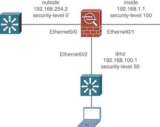
Figure 3-14. Example ASA with Interface Names and Unique Security Levels
By default, interface security levels must be unique so that the ASA can apply security policies across security-level boundaries. This is because of the two following inherent policies that an ASA uses to forward traffic between its interfaces:
• Traffic is allowed to flow from a higher-security interface to a lower-security interface (inside to outside, for example), provided that any access list, stateful inspection, and address translation requirements are met.
• Traffic from a lower-security interface to a higher one cannot pass unless additional explicit inspection and filtering checks are passed.
This concept is shown in Figure 3-15, applied to an ASA with only two interfaces.
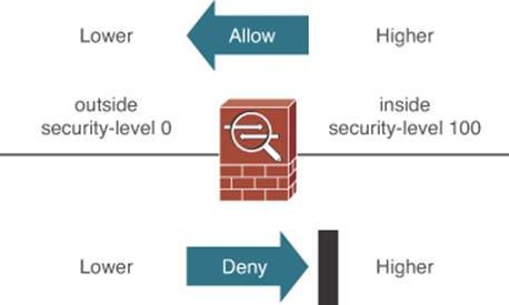
Figure 3-15. Inherent Security Policies Between ASA Interfaces
In addition, the same two security policies apply to any number of interfaces. Figure 3-16 shows an ASA with three different interfaces and how traffic is inherently permitted to flow from higher-security interfaces toward lower-security interfaces. For example, traffic coming from the inside network (security level 100) can flow toward the DMZ network (security level 50) because the security levels are decreasing. As well, DMZ traffic (security level 50) can flow toward the outside network (security level 0).
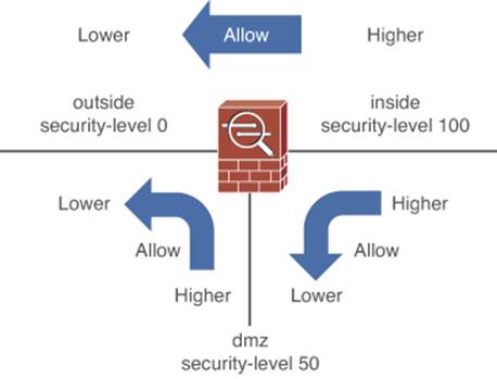
Figure 3-16. Traffic Flows Are Permitted from Higher to Lower Security Levels
Traffic that is initiated in the opposite direction, from a lower security level toward a higher one, cannot pass so easily. Figure 3-17 shows the same ASA with three interfaces and the possible traffic flow patterns.
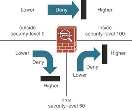
Figure 3-17. Traffic Flows Are Blocked from Lower to Higher Security Levels
You can assign a security level of 0 to 100 to an ASA interface with the following interface configuration command:
ciscoasa(config-if)# security-level level
From ASDM, you can set the security level when you edit an existing interface or add a new one.
Continuing from the configuration in the section, “Assigning an IP Address,” you can assign the outside interface with a security level of 0 by entering the following:
ciscoasa(config-if)# security-level 0
By default, interface security levels do not have to be unique on an ASA. However, if two interfaces have the same security level, the default security policy will not permit any traffic to pass between the two interfaces at all. You can override this behavior with the same-security-traffic permit inter-interface command.
In addition, there are two cases in which it is not possible to assign unique security levels to each ASA interface:
• The number of ASA interfaces is greater than the number of unique security level values: Because the security level can range from 0 to 100, there are 101 unique values. Some ASA platforms can support more than 101 VLAN interfaces, so it becomes impossible to give them all unique security levels. In this case, you can use the following command in global configuration mode so that you can reuse security level numbers and relax the security level constraint between interfaces, as shown in the left portion of Figure 3-18:
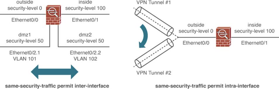
Figure 3-18. Permitting Traffic to Flow Across the Same Security Levels
ciscoasa(config)# same-security-traffic permit inter-interface
• Traffic must enter and exit through the same interface, traversing the same security level: When an ASA is configured to support logical VPN connections, multiple connections might terminate on the same ASA interface. This VPN architecture looks much like the spokes of a wheel, where the ASA interface is at the hub or center. When traffic comes from one VPN spoke and enters another spoke, it essentially enters the ASA interface and comes out of one VPN connection, only to enter a different VPN connection and go back out the same interface. In effect, the VPN traffic follows a hairpin turn on a single interface.
If an ASA is configured for VPN connections, you can use the following command in global configuration mode to relax the security level constraint within an interface, as shown in the right portion of Figure 3-18:
ciscoasa(config)# same-security-traffic permit intra-interface
If you are using ASDM, you can accomplish the same tasks from the Configuration > Device Setup > Interfaces using the two check boxes at the bottom of the interface list, as illustrated in Figure 3-19.
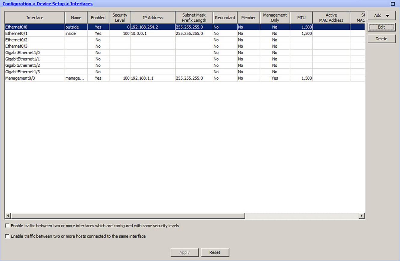
Figure 3-19. Check Boxes to Permit Traffic to Traverse the Same Security Levels
Interface Security Parameters Example
The ASA in Figure 3-14 has three interfaces. Example 3-12 shows the commands that can be used to configure each of the interfaces with the necessary security parameters.
Example 3-12. Configuring the ASA Interfaces from Figure 3-14
ciscoasa(config)# interface ethernet0/0
ciscoasa(config-if)# nameif outside
ciscoasa(config-if)# ip address 192.168.254.2 255.255.255.0
ciscoasa(config-if)# security-level 0
ciscoasa(config-if)# interface ethernet0/1
ciscoasa(config-if)# nameif inside
ciscoasa(config-if)# ip address 192.168.1.1 255.255.255.0
ciscoasa(config-if)# security-level 100
ciscoasa(config-if)# interface ethernet0/2
ciscoasa(config-if)# nameif dmz
ciscoasa(config-if)# ip address 192.168.100.1 255.255.255.0
ciscoasa(config-if)# security-level 50
As a comparison, Figure 3-20 shows the same outside interface configuration done in ASDM.
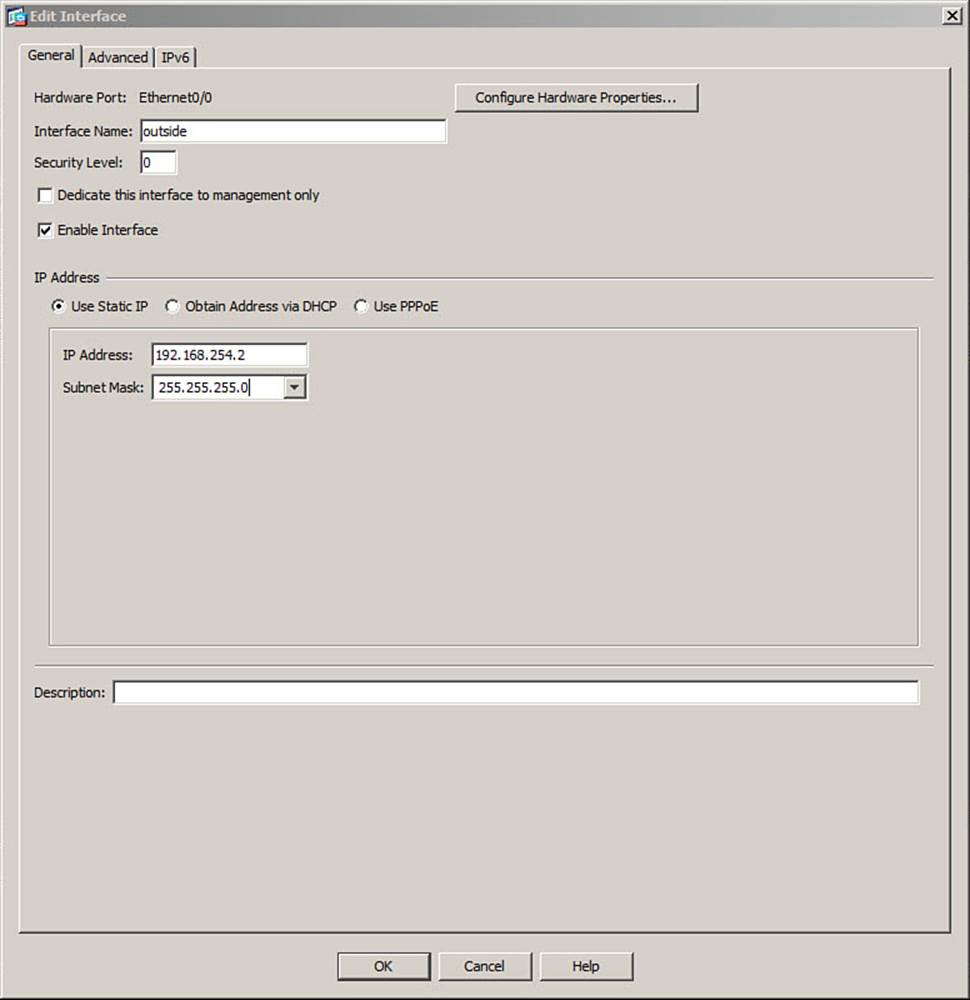
Figure 3-20. Configuring the Outside ASA Interface
Configuring the Interface MTU
By default, any Ethernet interface has its maximum transmission unit (MTU) size set to 1500 bytes, which is the maximum and expected value for Ethernet frames. If a packet is larger than the MTU, it must be fragmented before being transmitted. And before the packet can be presented at the destination, all of its fragments must be reassembled in their proper order.
The whole fragmentation and reassembly process takes time, memory, and CPU resources, so it should be avoided if possible. Normally, the default 1500-byte MTU is sufficient because Ethernet frames are limited to a standard maximum of 1500 bytes of payload data. Various IEEE standards use expanded frame sizes to carry additional information. As well, data centers often leverage Ethernet “giant” or “jumbo” frames, which are much larger than normal, to move large amounts of data efficiently.
If packets larger than 1500 bytes are commonplace in a network, you can increase the MTU size to prevent the packets from being fragmented at all. In some cases, you might need to reduce the MTU to avoid having to fragment encrypted packets where the encryption protocols add too much overhead to an already maximum-sized packet. Ideally, the MTU should be increased on every network device and interface along the entire data path.
To adjust the interface MTU from ASDM, first select Configuration > Device Setup > Interfaces, select an interface, and click the Edit button. Next, select the Advanced tab and enter the new MTU value, as shown in Figure 3-21. Although ASDM lets you type a new value, it won’t permit the value to change if the interface has not been configured with a name.
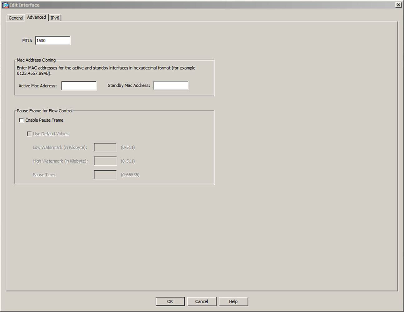
Figure 3-21. Configuring an Interface MTU in ASDM
To accomplish the same task from the CLI, you can use the following global configuration command to adjust the MTU on an ASA interface:
ciscoasa(config)# mtu if_name bytes
Identify the interface using its name, such as “inside” or “outside,” rather than the hardware name. The transmitted MTU can be sized from 64 to 9216 bytes.
You should also use the following interface configuration command to enable jumbo frame processing as frames are received on an interface:
ciscoasa(config-if)# jumbo-frame reservation
Although you can increase the MTU size on any ASA platform, be aware that the jumbo-frame reservation command is supported only on the ASA 5585-X.
You can display the current MTU configuration for all firewall interfaces by using the show running-config mtu command. Interface MTU settings are also displayed as a part of the show interface command output. Example 3-13 shows the output from each of the commands.
Example 3-13. Displaying the Interface MTU
ciscoasa# show running-config mtu
mtu outside 1500
mtu inside 1500
ciscoasa# show interface outside
Interface Ethernet0/0 "outside", is up, line protocol is up
Hardware is i82546GB rev03, BW 1000 Mbps, DLY 10 usec
Auto-Duplex(Full-duplex), Auto-Speed(100 Mbps)
Input flow control is unsupported, output flow control is unsupported
MAC address 001a.a22d.1ddc, MTU 1500
IP address 192.168.100.10, subnet mask 255.255.255.0
1996 packets input, 127860 bytes, 0 no buffer
Received 533 broadcasts, 0 runts, 0 giants
Verifying Interface Operation
To verify that an ASA interface is operating correctly, you can use the following command:
ciscoasa# show interface if_name
Here, you can specify either a hardware name, such as ethernet0/0, or an interface name, such as outside. The show interface command displays the current status, current speed and duplex mode, MAC address, IP address, and many statistics about the data being moved into and out of the interface. The command also lists traffic statistics, such as packets and bytes in the input and output directions, and traffic rates. The rates are shown as 1-minute and 5-minute averages. Example 3-14 shows a sample of the output.
Example 3-14. Sample Output from the show interface Command
ciscoasa# show interface ethernet0/0
Interface Ethernet0/0 "outside", is up, line protocol is up
Hardware is i82546GB rev03, BW 1000 Mbps, DLY 10 usec
Auto-Duplex(Full-duplex), Auto-Speed(100 Mbps)
Input flow control is unsupported, output flow control is unsupported
MAC address 001a.a22d.1ddc, MTU 1500
IP address 192.168.254.2, subnet mask 255.255.255.0
26722691 packets input, 27145573880 bytes, 0 no buffer
Received 62291 broadcasts, 0 runts, 0 giants
0 input errors, 0 CRC, 0 frame, 0 overrun, 0 ignored, 0 abort
0 pause input, 0 resume input
0 L2 decode drops
19039166 packets output, 5820422387 bytes, 0 underruns
0 output errors, 0 collisions, 0 interface resets
0 late collisions, 0 deferred
0 input reset drops, 0 output reset drops
0 rate limit drops
input queue (blocks free curr/low): hardware (255/253)
output queue (blocks free curr/low): hardware (255/255)
Traffic Statistics for "outside":
26722691 packets input, 27145573880 bytes
19039166 packets output, 5820422387 bytes
49550 packets dropped
1 minute input rate 16 pkts/sec, 16110 bytes/sec
1 minute output rate 17 pkts/sec, 16240 bytes/sec
1 minute drop rate, 0 pkts/sec
5 minute input rate 12 pkts/sec, 13867 bytes/sec
5 minute output rate 15 pkts/sec, 15311 bytes/sec
5 minute drop rate, 0 pkts/sec
ciscoasa#
You can verify the interface status in the second line of output. If the interface is shown as “up,” the interface has been enabled. If the line protocol is shown as “up,” there is an active link between the ASA interface and some other device.
To display a summary of all ASA interfaces and their IP addresses and current status, you can use the show interface ip brief command, as shown in Example 3-15.
Example 3-15. Sample Output from the show interface ip brief Command
ciscoasa# show interface ip brief
Interface IP-Address OK? Method Status Protocol
Ethernet0/0 192.168.254.2 YES manual up up
Ethernet0/1 10.0.0.1 YES manual up up
Ethernet0/2 unassigned YES unset administratively down down
Ethernet0/3 unassigned YES unset administratively down down
Internal-Data0/0 unassigned YES unset administratively down up
Management0/0 192.168.1.1 YES manual up up
GigabitEthernet1/0 unassigned YES unset administratively down down
GigabitEthernet1/1 unassigned YES unset administratively down down
GigabitEthernet1/2 unassigned YES unset administratively down down
GigabitEthernet1/3 unassigned YES unset administratively down down
Internal-Data1/0 unassigned YES unset up up
ciscoasa#
You can monitor the redundant interface status with the following command:
ciscoasa# show interface redundant number
Example 3-16 shows the output for interface redundant 1. Notice that physical interface Ethernet0/0 is currently the active interface, while Ethernet0/1 is not. The output also reveals the date and time of the last switchover.
Example 3-16. Verifying the Status of a Redundant Interface
ciscoasa# show interface redundant 1
Interface Redundant1 "inside", is up, line protocol is up
Hardware is i82546GB rev03, BW 100 Mbps, DLY 1000 usec
Auto-Duplex(Full-duplex), Auto-Speed(100 Mbps)
MAC address 0016.c789.c8a5, MTU 1500
[output omitted for clarity]
Redundancy Information:
Member Ethernet0/0(Active), Ethernet0/1
Last switchover at 01:32:27 EDT Sep 24 2010
ciscoasa#
Exam Preparation Tasks
As mentioned in the section, “How to Use This Book,” in the Introduction, you have a couple of choices for exam preparation: the exercises here, Chapter 17, “Final Preparation,” and the exam simulation questions on the CD-ROM.
Review All Key Topics
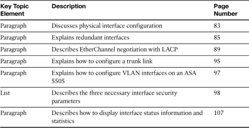
Review the most important topics from inside the chapter, noted with the Key Topics icon in the outer margin of the page. Table 3-3 lists a reference of these key topics and the page numbers on which each is found.
Table 3-3. Key Topics for Chapter 3
Define Key Terms
Define the following key terms from this chapter and check your answers in the glossary:
hardware name
interface name
security level
physical interface
redundant interface
member interface
EtherChannel
LACP
VLAN interface
VLAN trunk link
MTU
Command Reference to Check Your Memory
This section includes the most important configuration and EXEC commands covered in this chapter. It might not be necessary to memorize the complete syntax of every command, but you should be able to remember the basic keywords that are needed.
To test your memory of the commands, cover the right side of Table 3-4 with a piece of paper, read the description on the left side, and then see how much of the command you can remember.
Table 3-4. Commands Related to ASA Interface Configuration and Verification
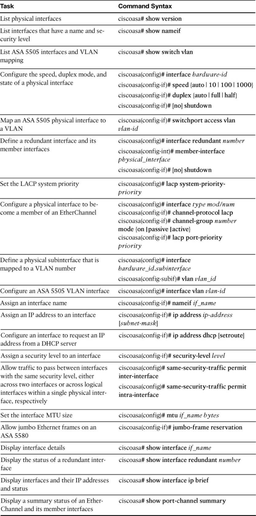
The FIREWALL exam focuses on practical, hands-on skills that are used by a networking professional. Therefore, you should be able to identify the commands needed to configure and test an ASA feature.
All materials on the site are licensed Creative Commons Attribution-Sharealike 3.0 Unported CC BY-SA 3.0 & GNU Free Documentation License (GFDL)
If you are the copyright holder of any material contained on our site and intend to remove it, please contact our site administrator for approval.
© 2016-2026 All site design rights belong to S.Y.A.