CCNP Security FIREWALL 642-618 Official Cert Guide (2012)
Chapter 4. Configuring IP Connectivity
This chapter covers the following topics:
• Deploying DHCP Services: This section covers how a Cisco ASA can operate as a DHCP server and a DHCP relay. These functions support dynamic addressing for protected hosts, either by the ASA or by an external dedicated DHCP server.
• Using Routing Information: This section presents an overview of the various sources of routing information and how an ASA can use them.
• Configuring Static Routing: This section covers manual configuration of static routes, as well as static route tracking, which can make static routes respond to changing conditions.
• Routing with RIPv2: This section covers the Routing Information Protocol (RIP) version 2 dynamic routing protocol.
• Routing with EIGRP: This section covers the Enhanced Interior Gateway Routing Protocol (EIGRP) and how it can provide an ASA with dynamic routing information.
• Routing with OSPF: This section covers the Open Shortest Path First (OSPF) dynamic routing protocol and how an ASA can interact with other OSPF routers.
• Verifying the ASA Routing Table: This section provides an overview of some tools you can use to verify the information in an ASA’s routing table and the relationship with neighboring routers.
This chapter covers two ways that a Cisco Adaptive Security Appliance (ASA) can help provide IP addressing information for hosts that it protects on a network—by operating as a DHCP server or as a DHCP relay.
Once you configure ASA interfaces with IP addresses, an ASA can inherently reach other devices that are connected to those interfaces and located on the respective IP subnets. But, before an ASA can reach other subnets and networks that are located outside its immediate surroundings, it must use either static routing information that you have configured manually or routing information exchanged dynamically with other Layer 3 routing devices.
This chapter discusses each of these topics in detail.
“Do I Know This Already?” Quiz
The “Do I Know This Already?” quiz allows you to assess whether you should read this entire chapter thoroughly or jump to the “Exam Preparation Tasks” section. If you are in doubt about your answers to these questions or your own assessment of your knowledge of the topics, read the entire chapter. Table 4-1 lists the major headings in this chapter and their corresponding “Do I Know This Already?” quiz questions. You can find the answers in Appendix A, “Answers to the ‘Do I Know This Already?’ Quizzes.”
Table 4-1. “Do I Know This Already?” Section-to-Question Mapping
Caution
The goal of self-assessment is to gauge your mastery of the topics in this chapter. If you do not know the answer to a question or are only partially sure of the answer, you should mark that question as wrong for purposes of the self-assessment. Giving yourself credit for an answer you correctly guess skews your self-assessment results and might provide you with a false sense of security.
1. Which one of the following is a valid scenario for using the DHCP relay feature on an ASA?
a. A group of users and a DHCP server are located on the same ASA interface.
b. A group of users is located on one ASA interface; a DHCP server is located on another ASA interface.
c. A group of users is located on an ASA interface, but no DHCP server exists.
d. Malicious users attempt to exploit DHCP requests.
2. Which one of the following represents the complete command to enable the DHCP server feature on an ASA?
a. dhcp server enable
b. dhcpd
c. dhcpd enable
d. dhcpd enable inside
3. Which source of routing information is considered to be the most stable?
a. Static routes
b. Routes learned through RIPv2
c. Routes learned through EIGRP
d. Routes learned through OSPF
4. Which of the following are recommended practices when configuring routing on an ASA? (Choose all that apply.)
a. Always use OSPF whenever possible.
b. Always rely on static routing unless the size of the network is too large.
c. Always authenticate all dynamic routing protocol peers.
d. Use route filtering to choose one routing protocol over another.
5. If static routes are the most trusted, which one of the following sources of routing information is the next most trusted?
a. EIGRP internal
b. RIPv2
c. OSPF
d. Directly connected route
6. Which of the following represents a correct command syntax for configuring a default route on an ASA? (Choose all that apply.)
a. route outside default 10.10.10.10
b. route outside 0.0.0.0 0.0.0.0 10.10.10.10
c. route outside 0 0 10.10.10.10
d. ip route outside 0.0.0.0 0.0.0.0 10.10.10.10
7. Which ASA feature is used as the basis for tracking a static route based on the results of pinging a target address?
a. ICMP tracking
b. Reverse route injection
c. SLA monitor
d. Object grouping
8. Which of the following enables RIPv2 on an ASA?
a. ripv2 enable
b. router ripv2
c. router rip
version 2
d. router rip
9. The following configuration commands are entered into an ASA. Which of the following answers are correct regarding the inside network? (Choose all that apply.)
router eigrp 100
network 192.168.1.0
passive-interface inside
a. The inside interface subnet will be advertised.
b. The inside interface subnet will not be advertised.
c. The ASA will discover an EIGRP peer on its inside interface.
d. The ASA will not discover an EIGRP peer on its inside interface.
10. If an ASA connects to OSPF area 0 on its inside interface and OSPF area 1 on its dmz interface, it is called which one of the following?
a. ABR
b. ASBR
c. SPF
d. Nothing; this is an invalid configuration.
11. Suppose you have configured OSPF on an ASA, but the show ospf neighbor command displays no active OSPF peers. Which one of the following could be the cause of the problem?
a. The MD5 authentication key entered on the ASA doesn’t match the key entered on any OSPF peer.
b. The ASA has not been configured with any access list rules to permit OSPF traffic.
c. You forgot to enter the copy running-config startup-config command.
d. The ASA and any neighboring routers should not be configured with the same OSPF area.
12. Which one of the following commands can be used to display the routing table on an ASA?
a. show routing-table
b. show ip route
c. show route
d. show run route
Foundation Topics
To forward traffic between its interfaces, an ASA must know how to reach other subnets and networks located outside its immediate surroundings. You can configure an ASA to use static routing information or information exchanged dynamically with other routing devices.
You can also configure an ASA to provide various DHCP services so that hosts connected to its interfaces can get their IP addresses dynamically.
This chapter discusses each of these topics in detail.
Deploying DHCP Services
Client devices that are connected to a network need to use unique IP addresses so that they can communicate. Although a client can be configured with a static IP address, most often it relies on a DHCP server to provide an IP address that can be “checked out” or leased for a period of time.
When a network architecture includes an ASA, either the clients have no local DHCP server or the clients can become separated or isolated from a working DHCP server. You can configure an ASA to assist the clients in either of these cases, as described in the sections that follow.
Configuring a DHCP Relay
When a client needs an IP address for itself, it sends a DHCP request, hoping that a DHCP server can hear the request and answer. DHCP requests are normally sent as broadcasts, because the DHCP server address is not known ahead of time. Therefore, a DHCP server must be located within the same broadcast domain as a client.
When an ASA is introduced into a network, it might also introduce a new security domain boundary that separates clients from a DHCP server. For example, a group of clients might be connected to one ASA interface, and the DHCP server might be connected to a different interface. By default, an ASA will not forward DHCP requests from one of its interfaces to another.

You can configure an ASA to use the DHCP relay agent feature to relay DHCP requests (broadcasts) received on one interface to a DHCP server found on another interface. The ASA does this by converting the requests to UDP port 67 unicast packets. The ASA can also intercept the DHCP replies that are returned by the DHCP server so that the default router address can be changed to become the IP address of the ASA itself.
Note
Once you enable the DHCP relay agent, the ASA will handle the DHCP packets as they are sent and received. You do not have to configure any specific rules or security policies to permit the DHCP packets to pass through any of the ASA interfaces.
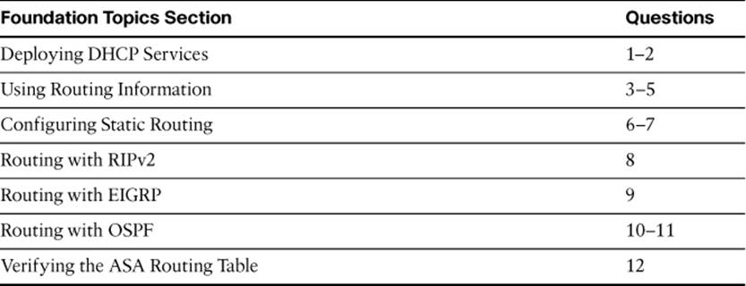
To enable the DHCP relay agent in ASDM, select Configuration > Device Management > DHCP > DHCP Relay and click the Add button. Define the IP address of a DHCP server and identify the ASA interface where the server can be found. In Figure 4-1, a DHCP server is at 192.168.50.11, located on the ASA’s dmz interface.
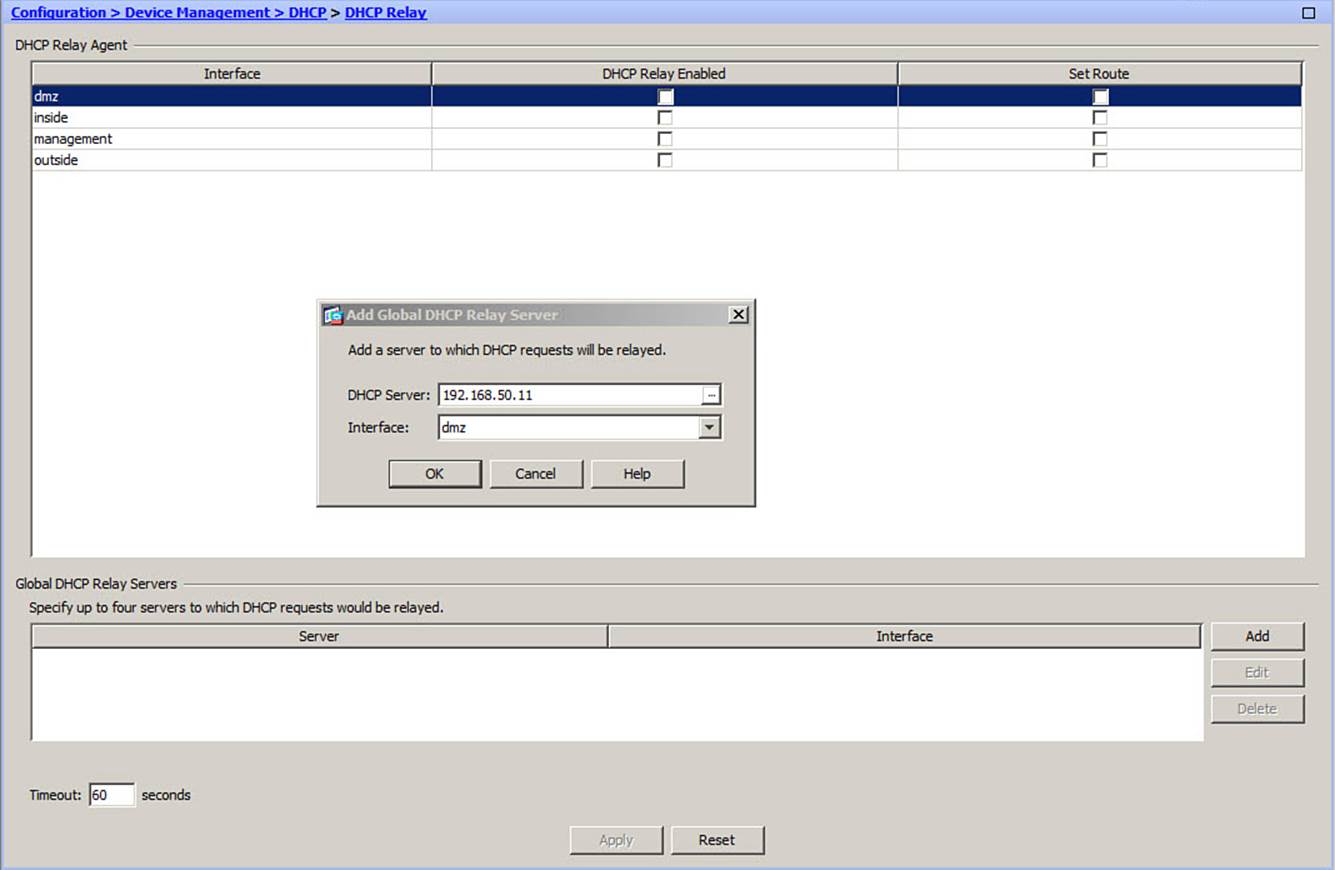
Figure 4-1. Defining a DHCP Server for the DHCP Relay Agent in ASDM
Next, look through the list of DHCP relay agent interfaces and find the one where the DHCP clients are located. Check the DHCP Relay Enabled check box to enable DHCP relay on that interface. You can check the Set Route check box to override the default gateway parameter in DHCP replies with the ASA interface address, as shown in Figure 4-2. The DHCP clients are located on the inside interface.
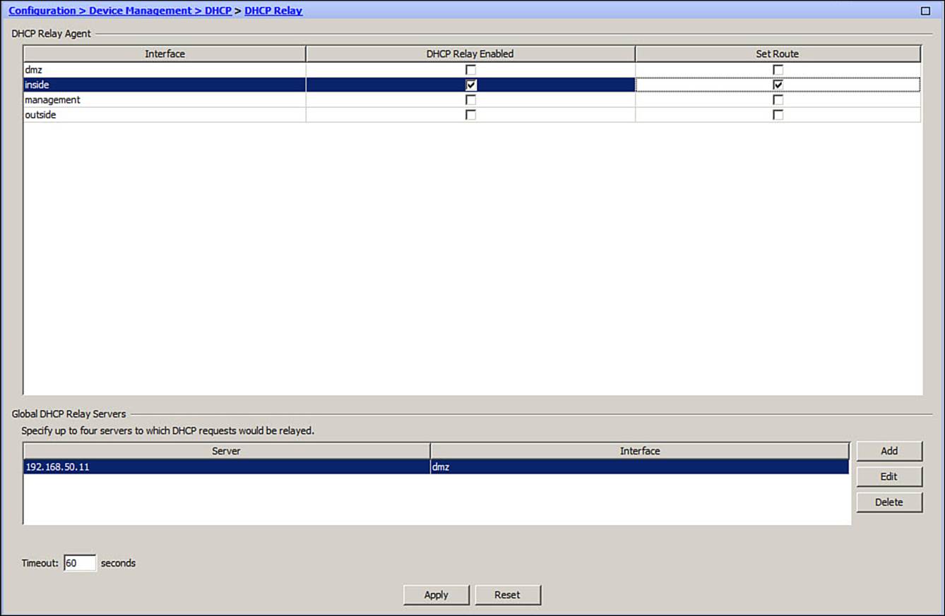
Figure 4-2. Enabling the DHCP Relay Feature on an ASA Interface
You can use the CLI to configure DHCP Relay with the following steps:
Step 1. Identify the DHCP server and its location:
ciscoasa(config)# dhcprelay server ip-address interface
If you have more than one DHCP server, you can repeat this command to define up to four different servers. In this case, the DHCP requests are relayed to each of the servers simultaneously.
Step 2. Identify the DHCP client locations:
ciscoasa(config)# dhcprelay enable interface
Step 3. Override the default router returned in the DHCP offers:
ciscoasa(config)# dhcprelay setroute interface
Example 4-1 shows the configuration commands that can be used to enable the DHCP relay agent for the clients located on the inside interface, where the server is located on the dmz interface.
Example 4-1. Configuring the DHCP Relay Agent Feature
ciscoasa(config)# dhcprelay server 192.168.50.11 dmz
ciscoasa(config)# dhcpreley enable inside
ciscoasa(config)# dhcprelay setroute inside
Configuring a DHCP Server
In some cases, a network might not have a dedicated DHCP server. You can configure an ASA to act as a DHCP server, assigning IP addresses dynamically to requesting clients. The DHCP server can also generate dynamic DNS information, allowing DNS records to be updated dynamically as hosts acquire an IP address.
An ASA will return its own interface address for the client to use as the default gateway. The interface subnet mask is returned for the client to use as well. You can define and enable DHCP servers on more than one interface, if clients are located there.
Note
No provisions are available for configuring static address assignments. An ASA can manage only dynamic address assignments from a pool of contiguous IP addresses.
As an example, suppose an ASA is configured as a DHCP server for clients on its inside interface. The inside interface has already been configured with IP address 192.168.10.1. The clients are to be assigned an address from the pool 192.168.10.10 through 192.168.10.254. The clients should also receive DNS addresses 192.168.1.20 and 192.168.1.21, WINS addresses 192.168.1.22 and 192.168.1.23, and a default domain name of mynewnetwork.com.
Figure 4-3 shows how you can begin to configure the scenario through ASDM. Navigate to Configuration > Device Management > DHCP > DHCP Server. Select the interface that will face the DHCP clients and click the Edit button. Check the Enable DHCP Server check box to enable the service, and then specify the first and last IP address in the DHCP address pool. You can also enter DNS, WINS, and a domain name that are specific to this DHCP scope, if needed; otherwise, leave those fields blank and click the OK button.
Figure 4-3. Configuring the DHCP Server Feature with ASDM
Next, in the Configuration > Device Management > DHCP > DHCP Server window, enter the values for global DNS and WINS, as well as a domain name. These parameters apply to all DHCP scopes on the ASA, as long as they are not overridden with specific values in a scope. InFigure 4-4, the global parameters for the example scenario are entered.
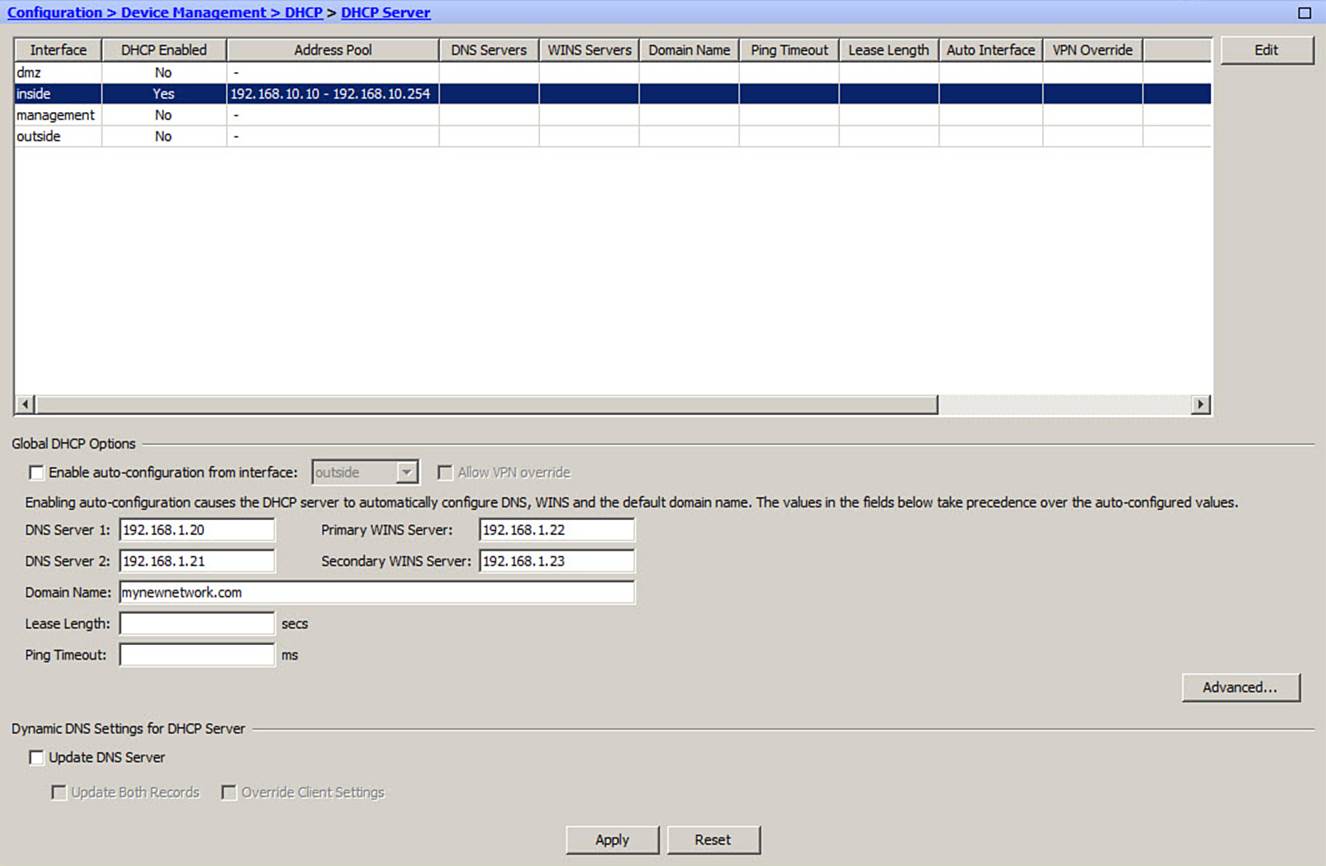
Figure 4-4. Entering Global DHCP Server Parameters
Alternatively, you can configure the DHCP server feature from the CLI by using the following steps:
Step 1. Enable the DHCP server on an ASA interface that faces the clients:
ciscoasa(config)# dhcpd enable interface
Step 2. Create an address pool for clients on an interface:
ciscoasa(config)# dhcpd address ip1[-ip2] interface
The DHCP scope of IP addresses begins with ip1 and ends with ip2. These two addresses must be separated by a hyphen and must belong to the same subnet. In addition, the pool of addresses must reside in the same IP subnet assigned to the ASA interface.
Step 3. Configure DHCP options for clients.
You can use the dhcp option command to define any specific DHCP options that clients need to receive. With the following command syntax, you can configure an option code number with an ASCII string, an IP address, or a hex string:
ciscoasa(config)# dhcpd option code {ascii string | ip ip_address |
hex hex_string}
As an example, you might want to hand out DHCP option 66 (TFTP server) or DHCP option 150 (multiple TFTP servers) to Cisco IP Phone clients. By default, an ASA hands out its own interface address as the client’s default gateway, but you can override that value by configuring an IP address with DHCP option 3 (default router).
Step 4. Configure any global DHCP parameters.
Some parameters are global in nature and can be handed out in all DHCP replies. You can define the DNS and WINS server addresses and the default domain name with the following commands, respectively:
ciscoasa(config)# dhcpd dns dns1 [dns2]
ciscoasa(config)# dhcpd wins wins1 [wins2]
ciscoasa(config)# dhcpd domain domain_name
By default, each DHCP lease is sent with a lease time of 3600 seconds, or 1 hour. You can override that value globally with the following command, where the lease length is given in seconds:
ciscoasa(config)# dhcpd lease lease_length
Finally, when an ASA receives a DHCP request from a potential client, it looks up the next available IP address in the pool. Before a DHCP reply is returned, the ASA sends an ICMP echo (ping) as a test to make sure that the IP address is not already in use by some other host. By default, the ASA waits 750 ms for an ICMP reply; if no reply is received, it assumes that the IP address is indeed available and assigns it to the client. If an ICMP reply is received from that address, the firewall knows that the address is already taken, so the next address from the pool is tried.
You can override the ping test timer by issuing the following command with a timeout (100 to 10,000) in milliseconds:
ciscoasa(config)# dhcpd ping_timeout timeout
Example 4-2 shows the commands that you can use to configure the example scenario on the ASA.
Example 4-2. Configuring the DHCP Server Feature
ciscoasa(config)# dhcpd enable inside
ciscoasa(config)# dhcpd address 192.168.10.10-192.168.10.254 inside
ciscoasa(config)# dhcpd dns 192.168.1.20 192.168.1.21
ciscoasa(config)# dhcpd wins 192.168.1.22 192.168.1.23
ciscoasa(config)# dhcpd domain mynewnetwork.com
You can verify the DHCP server operation with the show dhcpd state EXEC command. As well, you can display the active DHCP leases with the show dhcpd binding all command.
Using Routing Information
Once you configure an IP address and a subnet mask on an ASA interface, the entire IP subnet used on that interface becomes reachable from the ASA. This is known as a directly connected subnet or route. Before the ASA can forward packets toward other subnets that are not directly connected, it needs additional routing information.
An ASA keeps a table of routes to all IP subnets that are known to it. At a minimum, each route contains an IP subnet, a subnet mask, and the IP address of the next-hop router that can reach the subnet. By default, the routing table is populated with every directly connected subnet, where the next hop is the ASA’s own interface. An ASA can also import routing information into its routing table from the following sources:
• Static routes: Routes that are manually configured and do not change.
• RIP version 2: Routes learned dynamically from other routers running the Routing Information Protocol version 2 (RIPv2); RIPv1 is also supported, but is not covered on the FIREWALL exam.
• EIGRP: Routes learned dynamically from other routers running the Enhanced Interior Gateway Routing Protocol (EIGRP).
• OSPF: Routes learned dynamically from other routers running the Open Shortest Path First (OSPF) routing protocol.
An ASA can also advertise routes found in its own routing table to other routers running the RIPv2, EIGRP, and OSPF routing protocols. If multiple routing protocols are used, an ASA can even redistribute routing information from one protocol into another.
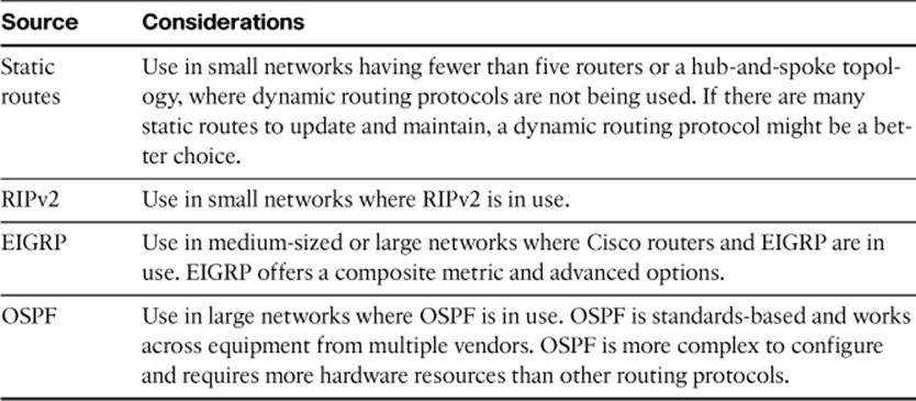
With so many choices for routing information exchange, how should you go about choosing and configuring an ASA? First, decide if there are other subnets in the network that are not directly connected to the ASA, but must be reachable from the ASA. Typically, these subnets are found on the trusted or secure interfaces. All subnets that are found on the outside, or untrusted, interface can be summarized by a default “catch all” route.
In a small network environment, you might find that there are no other subnets besides those that are directly connected. In that case, no other routing information is needed beyond a static default route leaving the outside interface.
If there are other subnets, begin considering how the ASA can learn about them. Use Table 4-2 as a general guide for choosing static routing or a dynamic routing protocol.
Table 4-2. Considerations for Routing Information Sources
If no other routers in the network are running dynamic routing protocols, it doesn’t make sense to configure a routing protocol on the ASA. Configure a routing protocol on an ASA interface only if there is a neighboring router that can exchange routing information. You can configure different routing protocols on different ASA interfaces, if necessary.
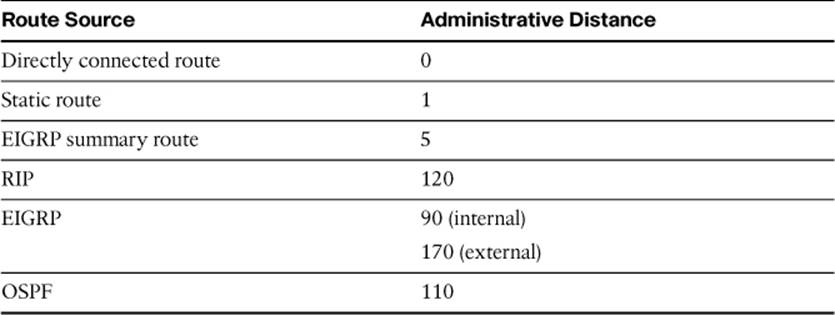
If various sources of routing information are used, the same subnet or route could be learned by more than one method. For example, suppose the route 10.10.0.0/16 has been configured as a static route, but has also been learned via RIP and OSPF. Each of the routing sources might come up with different next-hop addresses for the route, so which one should the ASA trust?
To prevent any confusion, some sources are generally considered to be more trustworthy than others. The degree of trustworthiness is given by the administrative distance, an arbitrary value from 0 to 255. Routes with a distance of 0 are the most trusted, whereas those with a distance of 255 are the least trusted. Table 4-3 lists the administrative distances for every possible source of routing information. Notice that directly connected routes are the most trusted, followed by static routes that are manually configured.
Table 4-3. Administrative Distance Values for Routing Information Sources
Consider the following rules of thumb when you are planning to use dynamic routing protocols on an ASA:
• Static routing is always preferred over dynamic routing protocols, because of the manual, trusted configuration and route stability. If static routing is impractical or cumbersome, consider dynamic routing protocols.
• Always use peer authentication with a dynamic routing protocol. However, you should never use cleartext authentication; use MD5 instead.
• Use route filtering to prevent internal, private subnets from being leaked or advertised to the unsecure side.
• Use route filtering to prevent spoofed or bogus routing information from being learned. This is especially important when the ASA must peer with untrusted routers.
• Use route summarization if possible, to reduce the complexity of routing information that is advertised from the ASA.
Although the following sections explain how to configure each source of routing information, this chapter is not meant to be a comprehensive source of information about each dynamic routing protocol. Instead, it explains the most common features that can be configured on an ASA, as included in the CCNP Security FIREWALL course and exam. You should already have a foundation in routing topics from the CCNA and CCNP ROUTE courses and exams.
Configuring Static Routing
Static routes are manually configured and are not learned or advertised by default. An IP subnet defined by an IP address and a subnet mask can be reached by forwarding packets out a specific ASA interface. The packets are forwarded to the next-hop gateway address By default, a static route receives an administrative distance of 1. You can override this behavior by specifying a distance value of 1 to 255.
As an example, suppose an ASA has its inside interface configured for the 192.168.10.0/24 subnet. The ASA will automatically define a directly connected route to 192.168.10.0 255.255.255.0 using its inside interface. In addition, the 192.168.200.0/24 subnet can be found through gateway 192.168.10.254 located on the inside interface. Because this subnet isn’t directly connected, you can configure a static route to reach it
You can configure static routes in ASDM by navigating to Configuration > Device Setup > Routing > Static Routes. In Figure 4-5, a new static route for subnet 192.168.200.0/24 and gateway 192.168.100.254 is being added. Don’t forget to click the Apply button to apply the newly configured route to the ASA running configuration.
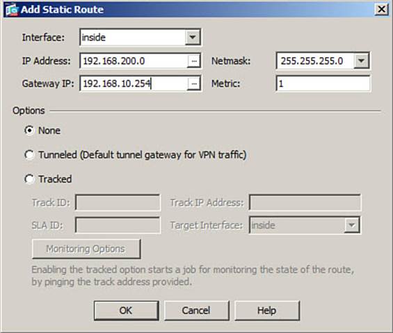
Figure 4-5. Adding a New Static Route with ASDM
A default route is a special-case static route, where the IP address and subnet mask are written as 0.0.0.0 0.0.0.0 (or more simply as 0 0 to save typing) to represent any address. The ASA must assume that the next-hop router or gateway listed in the default route knows how to reach any destination that isn’t found in the ASA’s routing table.
You can configure up to three different default routes on an ASA. If more than one default route exists, the ASA will distribute outbound traffic across the default-route next-hop gateways to load balance the traffic. In Figure 4-6, the list of static routes has grown after a default route has been added for network 192.168.200.0/24, with a next-hop gateway of 192.168.10.254.
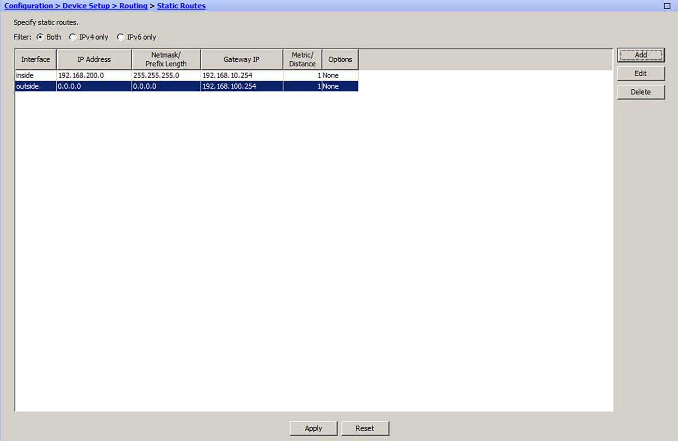
Figure 4-6. IDS and IPS Operational Differences
You can use the CLI to define a static route for an IP subnet by using the route configuration command, as follows:
ciscoasa(config)# route interface ip_address netmask gateway_ip [distance]
A static route for the example scenario can be configured by using the following command:
ciscoasa(config)# route inside 192.168.200.0 255.255.255.0 192.168.10.254
In the following command, a default route is created with a next-hop gateway at 192.168.100.254:
ciscoasa(config)# route outside 0.0.0.0 0.0.0.0 192.168.100.254
Tracking a Static Route
Normally, if a static route is configured, it stays active until it is manually removed with the no route configuration command. A static route is simply an unchanging definition of a next-hop destination, regardless of whether that destination is reachable. If a single Internet service provider (ISP) is the sole means of reaching the outside world, a static default route works nicely to point all outbound traffic to the ISP’s gateway address.
Suppose that you had connections to two ISPs, so you configured one default route to each. One ISP might be favored over the other, but the ASA will treat the default routes to each ISP equally and will try to balance the outbound traffic across the two connections. Even if the connection to one ISP goes down, the firewall will still use the static default route that points to that ISP as if nothing had happened—effectively sending some outbound traffic into a black hole.
You can leverage the static route tracking feature to make a static route conditional, based on the reachability of some target address. If the target address is reachable, the tracked static route remains active; if the target is not reachable, the static route becomes inactive, allowing other similar routes to be preferred. This allows you to configure multiple static or default routes without worrying about whether or not one ISP connection is working.
To make a static route conditional, you configure a service-level agreement (SLA) monitor process that monitors an arbitrary target address. That process is associated with a static route so that the route tracks the reachability of the target.
Figure 4-7 shows an example scenario where the ASA has two paths to the outside world. Therefore, it could be configured with two default routes that point to the two next-hop routers: 209.165.201.1 and 209.165.202.129. The link to 209.165.201.1 should be preferred and used, as long as the router 209.165.201.1 is alive and reachable; otherwise, the ASA should use the backup default route toward 209.165.202.129.
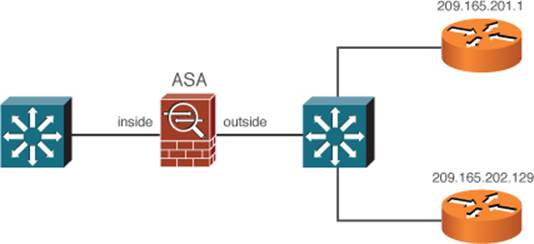
Figure 4-7. Tracking a Static Route
ASDM makes the tracked static route configuration quite easy. First, you must add a new static route by navigating to Configuration > Device Setup > Routing > Static Routes and clicking the Add button. Define the static route normally, but be sure to check the Tracked check box.
Then, in the same dialog box, you can define the SLA monitor test and the SLA target address. Click the Monitoring Options button to tune the SLA monitor test options, if needed. The options and their defaults are described in Table 4-4. Figure 4-8 shows how the example scenario from can be configured.
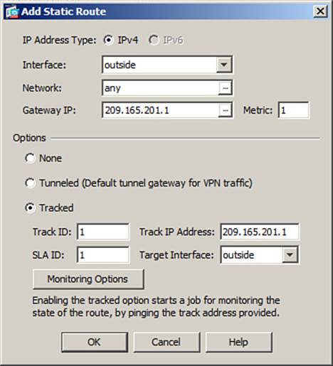
Figure 4-8. Configuring a Tracked Static Route in ASDM
Note
Before you configure the ICMP echo target address, you might want to manually test the target’s reachability with the ping target command.
Once you click OK, ASDM reminds you to define a backup route with a higher metric. Figure 4-9 shows a new static route being added with a metric of 100, which is higher than the tracked static route.
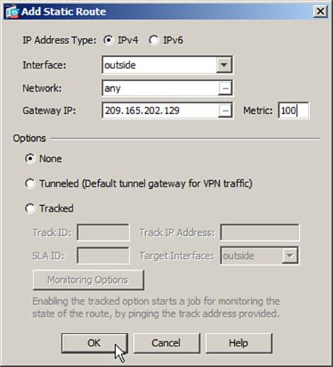
Figure 4-9. Configuring a Backup Default Route in ASDM
As an alternative, you can use the CLI to configure a tracked static route, though the process is a bit more complicated than ASDM. Use the following configuration steps to define an SLA process and then to bind it to a static route:
Step 1. Define an SLA monitor process and an arbitrary process number:
ciscoasa(config)# sla monitor sla-id
Step 2. Define the reachability test:
ciscoasa(config-sla-monitor)# type echo protocol ipIcmpEcho target
interface interface-name
Although the command syntax seems lengthy, it really isn’t too complex. The only test type is echo, which sends ICMP echo request packets to the target IP address found on the named ASA interface.
Step 3. Tune optional test parameters.
An SLA test has several parameters that you can change to tune the test according to your environment. Table 4-4 lists the parameters along with their default values and command syntax.
Table 4-4. Optional Parameters for an SLA Test
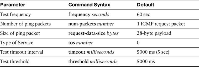
The test timeout interval is a rigid time period that determines when the echo test has failed. If the timeout interval has expired and no response has been received from the target, the target must be unresponsive.
An ASA also keeps track of a test threshold, which is used as an indicator that the target is getting increasingly hard to reach. The threshold isn’t used to decide whether the target is reachable. Instead, it can give you an idea of how realistic your choice of the timeout interval is.
By default, the threshold interval is set to 5000 ms (5 sec). You can set a different threshold value, but keep in mind that it must always be less than or equal to the timeout interval value.
For example, suppose you choose a timeout interval of 10,000 ms (10 sec) and a threshold value of 5000 ms. After many echo tests are run, you can look at the test statistics to see how often the threshold is exceeded. If it is rarely exceeded, you might decide to reduce the timeout value to something at or below the current threshold value. If you decide to reduce the timeout value, you should also reduce the threshold value.
Step 4. Schedule the SLA monitor test to run.
You can use the following command to run the SLA monitor test starting now and running continually forever:
ciscoasa(config)# sla monitor sla-id life forever now
The test continues to run until you manually remove it from the running configuration with the no sla monitor sla-id command.
Note
The sla monitor command has a much more complex syntax, as follows:
ciscoasa(config)# sla monitor schedule sla-id [life {forever | seconds}]
[start-time {hh:mm[:ss] [month day | day month] | pending |
now | after hh:mm:ss}] [ageout seconds] [recurring]
SLA monitor tests are meant to be more versatile than static route tracking requires. Be aware that you can set specific starting times and durations, although the life forever now keywords are most commonly used so that the test will always be running.
Step 5. Enable reachability tracking.
To use the SLA monitor test, you must identify the test as a trackable object using the following configuration command:
ciscoasa(config)# track track-id rtr sla-id reachability
The SLA monitor test identified by sla-id will be used to track reachability information. Each track process is known by its track-id index, an arbitrary value from 1 to 500. You should define a unique track index for each SLA monitor test that you configure, so that each test can be tracked independently.
Note
Don’t be confused by the rtr keyword in the command. The SLA feature originally was known as Response Time Reporter (RTR), but the keyword has not been updated to reflect the new naming scheme.
Step 6. Apply tracking to a static route:
ciscoasa(config)# route if_name ip_address netmask gateway_ip
[distance] track track-id
Notice that the normal static route command syntax is used, but the track keyword is added to make the static route conditional upon a tracked object (the SLA monitor test). If the test target is reachable (it returns ICMP echo replies to the ASA as expected), the static route will remain active in the routing table. If the target is not reachable (ICMP echo replies are not received as expected), the static route will remain in the running configuration, but will have a higher distance value and be less desirable than other identical routes in the routing table.
Therefore, be sure to give the tracked static route a very low distance value so that it will be preferred over any similar backup or secondary static routes while it is active. A distance value of 1 (the default) is commonly used.
Step 7. Define a backup static route:
ciscoasa(config)# route if_name ip_address netmask gateway_ip distance
Finally, you should define a backup route that will be preferred whenever the tracked static route becomes inactive. The backup and tracked static routes should be identical except for their distance values. The tracked static route should have a low distance so that it is normally preferred, while the backup static route should have a higher, less preferred, distance value.
Example 4-3 lists the commands that can be used to configure the ASA for the scenario shown in Figure 4-7. SLA monitor test 1 is configured to perform ICMP echo tests on the 209.165.201.1 router. Notice that the default route pointing toward 209.165.201.1 has a distance of 1, while the backup default route pointing toward 209.165.202.129 has a higher (less preferred) distance of 100.
Example 4-3. Static Route Tracking Configuration for Figure 4-7
ciscoasa(config)# sla monitor 1
ciscoasa(config-sla-monitor)# type echo protocol ipIcmpEcho 209.165.201.1
interface outside
ciscoasa(config-sla-monitor-echo)# exit
ciscoasa(config-sla-monitor)# exit
ciscoasa(config)# sla monitor schedule 1 life forever now
ciscoasa(config)# track 1 rtr 1 reachability
ciscoasa(config)# route 0.0.0.0 0.0.0.0 209.165.201.1 1 track 1
ciscoasa(config)# route 0.0.0.0 0.0.0.0 209.165.202.129 100
Static route tracking is a rather silent process, and an ASA won’t give you any obvious signs that it is actually testing the reachability. However, you can monitor the status of a tracking process with the show track EXEC command. You can also display details about the SLA monitor test with the show sla monitor configuration command. Example 4-4 shows the output from each of these commands.
Example 4-4. Displaying Information About Static Route Tracking
ciscoasa# show track
Track 1
Response Time Reporter 1 reachability
Reachability is Down
2 changes, last change 03:50:24
Latest operation return code: Timeout
Tracked by:
STATIC-IP-ROUTING 0
ciscoasa#
ciscoasa# show sla monitor configuration
SA Agent, Infrastructure Engine-II
Entry number: 1
Owner:
Tag:
Type of operation to perform: echo
Target address: 209.165.201.1
Interface: outside
Number of packets: 1
Request size (ARR data portion): 28
Operation timeout (milliseconds): 5000
Type Of Service parameters: 0x0
Verify data: No
Operation frequency (seconds): 60
Next Scheduled Start Time: Start Time already passed
Group Scheduled : FALSE
Life (seconds): Forever
Entry Ageout (seconds): never
Recurring (Starting Everyday): FALSE
Status of entry (SNMP RowStatus): Active
Enhanced History:
ciscoasa#
Routing with RIPv2
The Routing Information Protocol (RIP) is a distance-vector routing protocol that uses a simple router hop count to select the best path to a destination route. Routers running RIP exchange routing information broadcasts at regular intervals and when changes to the network topology occur.
RIP exists as two versions; by default, an ASA sends routing updates as RIPv1, but receives updates in either RIPv1 or RIPv2. RIPv1 supports only classful networks, and its routing advertisements are broadcast in the clear. With RIPv2, classless networks and authenticated advertisements are supported, making it the more flexible and secure version. In fact, the CCNP Security FIREWALL exam covers only RIPv2. The ASA supports automatic route summarization, where subnets are summarized into networks that fall on classful boundaries.
If you have routers running RIPv2 in your network, you might consider running RIPv2 on an ASA so that it can exchange routing information dynamically. Be aware that RIP is limited to a maximum hop count of 16 routers, so it is more suited to smaller networks. RIP is also relatively slow to converge when a network topology changes due to a failed link or router.
As an example, suppose you are asked to configure an ASA to participate in RIPv2 with another router on the inside interface. Only routes that begin with 192.168.x.x should be learned from the other router. The inside ASA interface is connected to the 192.168.1.0/24 network. MD5 authentication should be used for any routing information exchanges.
To configure the scenario in ASDM, navigate to Configuration > Device Setup > Routing > RIP. In the Setup section, you can check the box to enable RIP, disable auto-summarization, enable RIPv2, enable default information originate, and specify any passive interfaces, as shown inFigure 4-10.
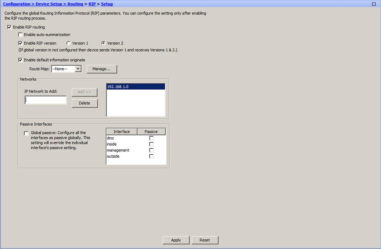
Figure 4-10. Configuring the RIPv2 Setup Section in ASDM
Next, go to the Interface section, select an interface that will participate in RIPv2, and then click the Edit button. In Figure 4-11, the inside interface is configured to use MD5 authentication and an authentication key.
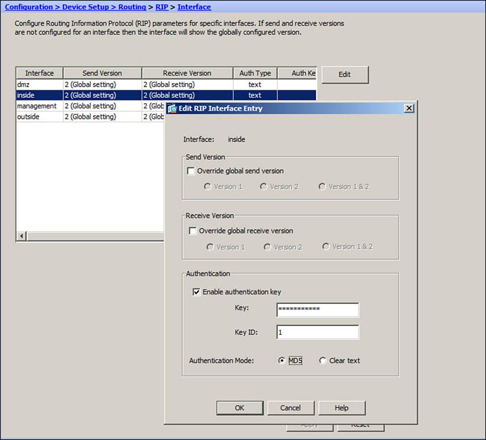
Figure 4-11. Configuring the RIPv2 Interface Section in ASDM
Next, click the Filter Rules section to configure any route filtering that is needed. In Figure 4-12, an access list has been configured to permit only routes containing the 192.168 prefix in the inbound direction.
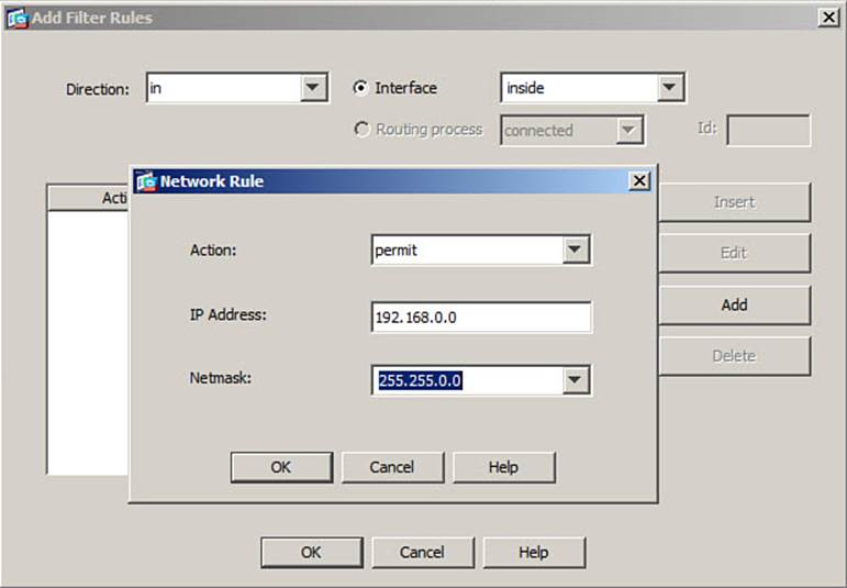
Figure 4-12. Configuring the RIPv2 Filter Rules Section in ASDM
As an alternative, you can use the following steps to configure RIPv2 on an ASA with the CLI:
Step 1. Enable RIPv2:
ciscoasa(config)# router rip
ciscoasa(config-router)# version 2
By default, automatic route summarization is enabled. To disable it, use the following command:
ciscoasa(config-router)# no auto-summary
If the ASA has a default route and you want it to be advertised to other RIPv2 routers, use the following command:
ciscoasa(config-router)# default-information originate
Step 2. Identify directly connected networks to advertise:
ciscoasa(config-router)# network ip-address
Once RIPv2 is enabled, the ASA will not advertise any of its own directly connected networks. In fact, the ASA won’t even participate in RIPv2 on any of its interfaces until you identify which networks it should use. By using the network command, you tell the ASA to enable RIPv2 on the interface that is connected to the IP subnet ip-address and to begin advertising that subnet.
Step 3. Identify any passive interfaces.
If there are ASA interfaces where routing information should be received but not transmitted, you can identify them as passive interfaces with the following command:
ciscoasa(config-router)# passive-interface {default | interface}
If you use the default keyword, all the firewall interfaces will become passive. Then, to explicitly permit an interface to actively participate in RIP, you must use the no passive-interface interface command.
Step 4. Optionally, filter routing information.
You can filter RIPv2 routing information that is sent or received on an ASA interface by applying a distribute list. In a nutshell, a distribute list uses a standard IP access list to identify specific routes; routes matching a permit statement are allowed to be used, whereas routes matching a deny statement are filtered out.
First, configure an access list that will identify the routes, and then bind the access list to a distribute list in the RIPv2 configuration, using the following commands:
ciscoasa(config)# access-list acl-id standard {permit | deny} ip-address
mask
ciscoasa(config-router)# distribute-list acl-id {in | out} interface
interface
Notice that the distribute list is applied in either the inbound or outbound direction, allowing routes to be filtered as they are received or transmitted, respectively.
Step 5. Use RIPv2 authentication on ASA interfaces.
Whenever you enable RIPv2 on an ASA, take every precaution to make sure that the routing information is coming from a trusted source. An ASA can support either cleartext or MD5 authentication to accomplish this. The same authentication method and key must be configured on each pair of RIPv2 peers. Because the cleartext key is passed along in the clear with routing updates, it is easily overheard and can be abused. Instead, you should use MD5 authentication, which passes an MD5 hash value that is computed on each routing advertisement and a hidden secret key.
RIPv2 authentication is configured on a per-interface basis. You can use the following interface configuration commands to select the authentication method and key:
ciscoasa(config-if)# rip authentication mode {text | md5}
ciscoasa(config-if)# rip authentication key key-string key_id id
The key-string field is a string of up to 16 characters. The key ID is a unique key identifier; although only one key can be used for RIPv2 authentication, you can define a different key number if you need to change keys periodically.
The commands listed in Example 4-5 can be used to configure the example scenario.
Example 4-5. RIPv2 Example Configuration
ciscoasa(config)# access-list ripfilter standard permit 192.168.0.0 255.255.0.0
ciscoasa(config)# router rip
ciscoasa(config-router)# version 2
ciscoasa(config-router)# no auto-summary
ciscoasa(config-router)# default-information originate
ciscoasa(config-router)# network 192.168.1.0
ciscoasa(config-router)# distribute-list ripfilter in interface inside
ciscoasa(config-router)# exit
ciscoasa(config)# interface ethernet0/1
ciscoasa(config-if)# rip authentication mode md5
ciscoasa(config-if)# rip authentication key myb1gs3cr3t key_id 1
Routing with EIGRP
The Enhanced Interior Gateway Routing Protocol (EIGRP) uses a complex routing metric that is based on a combination of delay, bandwidth, reliability, load, and MTU. EIGRP combines the advantages of link-state and distance-vector routing protocols, making it a hybrid of both methods.
EIGRP uses a neighbor discovery mechanism that works by sending hello messages to directly connected neighboring routers. Neighbors can be dynamically discovered or statically configured. All EIGRP messages, including the hello protocol, are sent as multicast packets to address 224.0.0.10, the “all EIGRP routers” address, using IP protocol 88.
EIGRP supports variable-length subnet masks (VLSM) and route summarization, providing plenty of flexibility in its routing information. It also uses the Diffusing Update
Algorithm (DUAL) to compute and maintain routing information from all of its neighbors. The ASA (or any other EIGRP router) always uses a feasible successor or a neighboring router with the lowest cost path to a destination.
EIGRP routers do not send periodic routing updates. Rather, routing information is exchanged only when a route’s metric changes, based on information from neighboring routers. If you have routers running EIGRP in your network, you might want to run EIGRP on your ASA too, so that the ASA can benefit from dynamic routing information. Be aware that an ASA can run only one EIGRP process.
As an example, suppose that an ASA has its Ethernet0/0 interface facing the outside, public network, while Ethernet0/1 faces the inside, protected network, as shown in Figure 4-13. EIGRP is being used on the internal network, due to the network’s size. The ASA will participate in EIGRP so that it can receive dynamic updates about internal IP subnets.
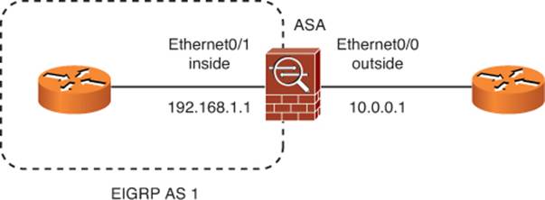
Figure 4-13. Example EIGRP Scenario
Because the ASA has only a single path to the outside world, it can become an EIGRP stub router. As well, there is no need for the outside interface to participate in routing updates because there is no trusted EIGRP neighbor there.
To configure the example scenario using ASDM, navigate to Configuration > Device Setup > Routing > EIGRP. Begin with the Setup option, where you enable EIGRP and set the autonomous system number, as shown in Figure 4-14. EIGRP routers can exchange routing information if they each belong to the same autonomous system. Make sure the autonomous system number (1 to 65,535) matches that of other EIGRP routers in your network.
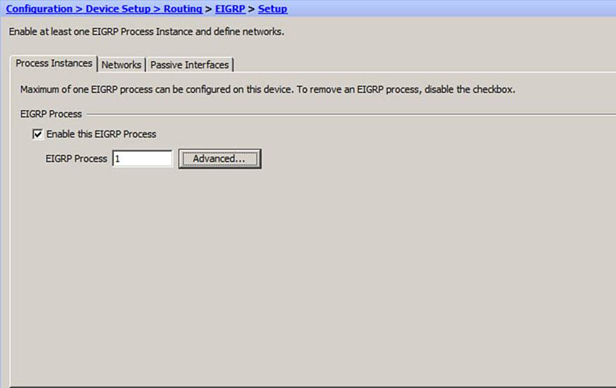
Figure 4-14. Configuring EIGRP Setup Parameters in ASDM
You can also click the Advanced button to configure autosummarization, set the default metric values, configure EIGRP stub routing, and tune the administrative distance.
Next, click the Networks tab within the Setup window and add any IP networks that will participate in EIGRP routing updates and which subnets to advertise, as shown in Figure 4-15.
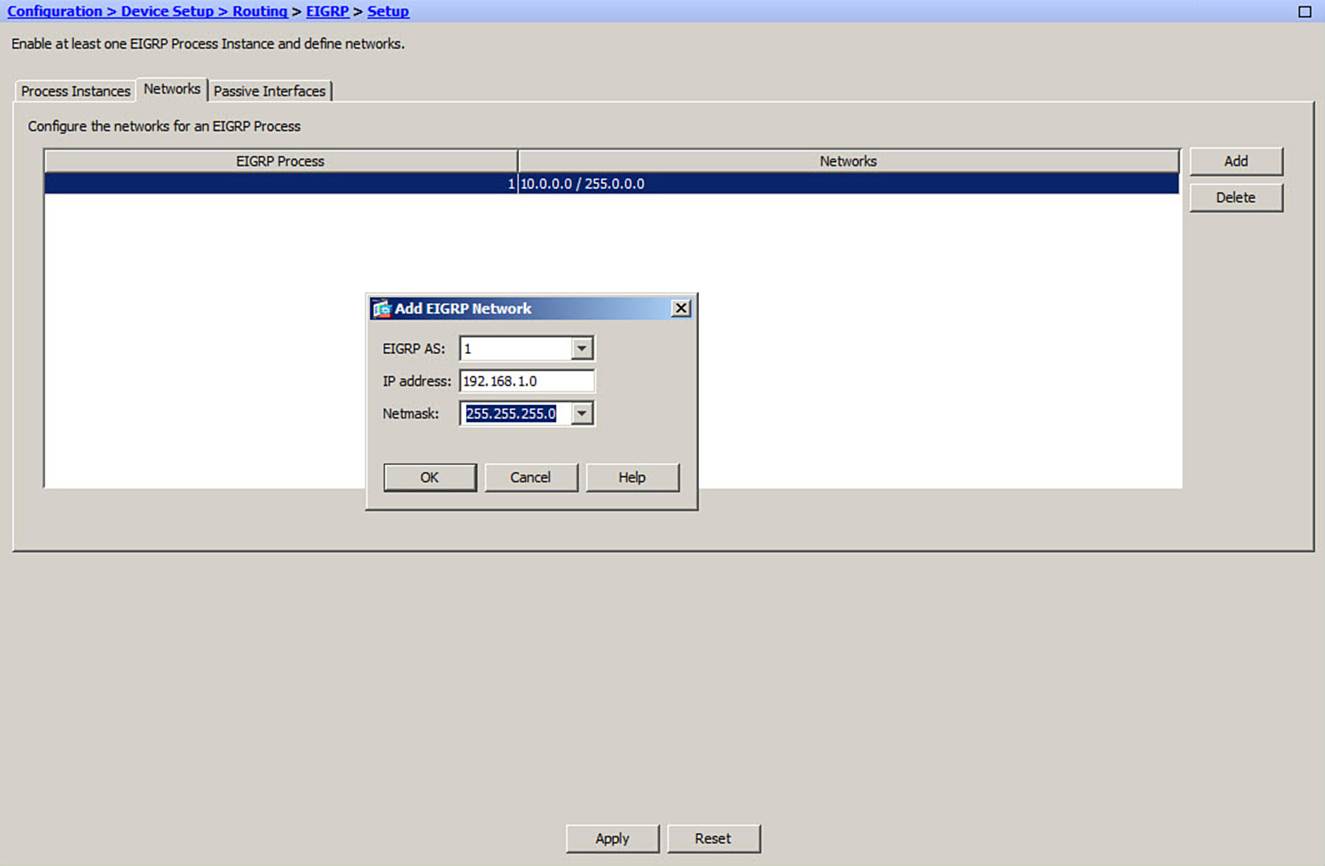
Figure 4-15. Configuring EIGRP Networks in the ASDM EIGRP Setup
Next, click the Passive Interfaces tab to identify any EIGRP passive interfaces. The subnet on a passive interface will be advertised, but the interface will not participate in EIGRP routing exchanges In Figure 4-16, the outside interface is configured to be passive.
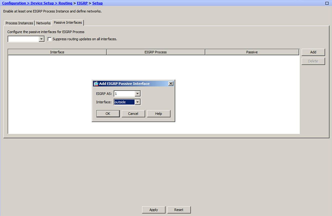
Figure 4-16. Configuring EIGRP Passive Interfaces in ASDM
To configure route filtering, choose Routing > EIGRP > Filter Rules and add any rules to a specific interface. Although route filtering is not used in the example scenario, the process is shown in Figure 4-17.
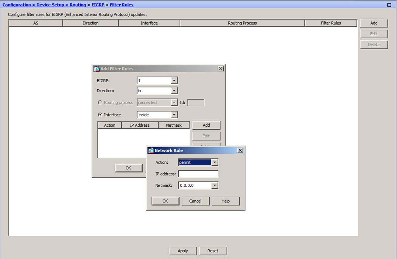
Figure 4-17. Configuring EIGRP Route Filtering in ASDM
Next, you can configure EIGRP authentication by choosing Routing > EIGRP > Interface, selecting an ASA interface, and then clicking Edit. You should always make sure that an ASA receives trusted routing information from neighboring routers by configuring MD5 authentication. Once authentication is enabled, any EIGRP neighbors that fail to present the correct key will be ignored. You can enable MD5 authentication and enter a key string and key identifier, as shown in Figure 4-18.
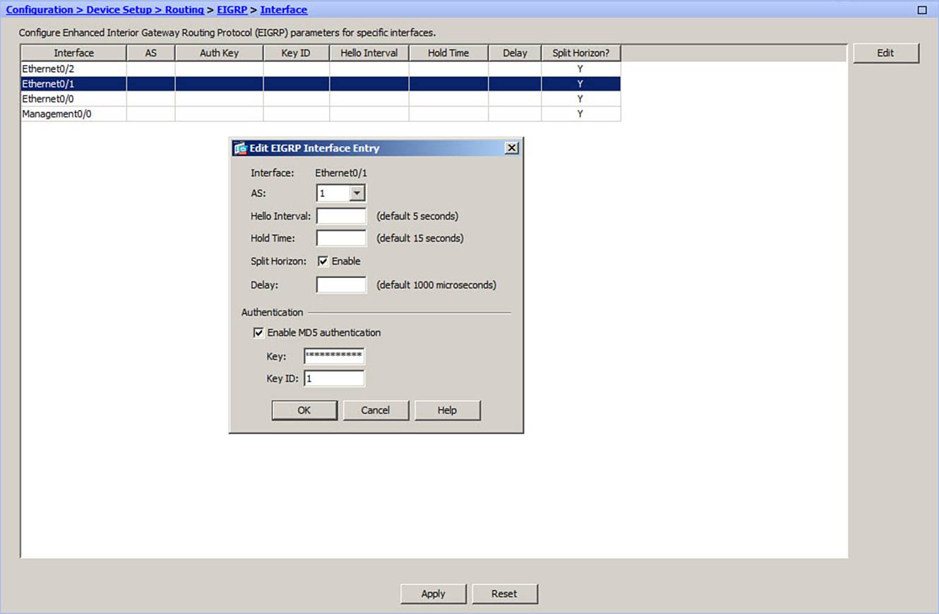
Figure 4-18. Configuring EIGRP Authentication in ASDM
An ASA can redistribute routes that it has learned from other sources into its EIGRP process. Directly connected and static routes, as well as routes learned from RIP or OSPF processes, can be redistributed. As a best practice, you should configure a route map to filter routing information from one routing protocol into EIGRP to prevent routing loops.
You should also define default metric values for all routes that are redistributed into EIGRP, because metrics from the different route sources are not equivalent. You can do this for each redistributed source or you can define a single set of default metrics for all sources that do not have explicit values defined.
To configure redistribution into EIGRP, navigate to Routing > EIGRP > Redistribution, click the Add button to add a routing source, and fill in the necessary parameters, as shown in Figure 4-19.
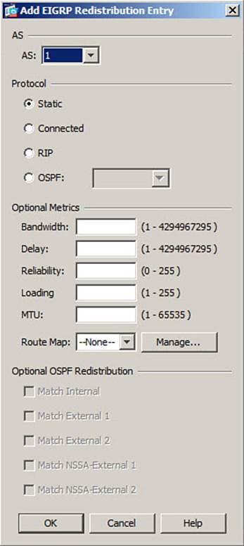
Figure 4-19. Configuring Route Redistribution into EIGRP from ASDM
You can configure any summary addresses by choosing Routing > EIGRP > Summary Address and then adding the network address, subnet mask, and interface, as shown in Figure 4-20. No summary addresses are used in the example scenario.
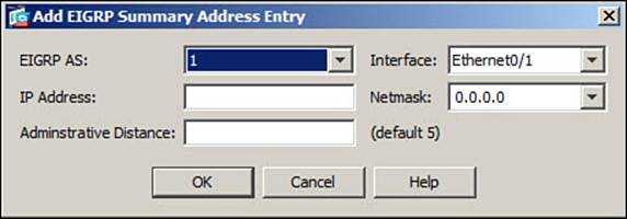
Figure 4-20. Configuring EIGRP Summary Addresses in ASDM
You can configure EIGRP with the CLI as well by using the following steps:
Step 1. Enable an EIGRP process:
ciscoasa(config)# router eigrp as-num
Step 2. Associate a network with the EIGRP process:
ciscoasa(config-router)# network ip-addr [mask]
EIGRP must know which interfaces will participate in routing updates and which interface subnets to advertise. If an interface address falls within the subnet ip-addr and mask, EIGRP will use it in its operation.
If you want the interface subnet to be advertised, but you don’t want the interface to participate in EIGRP routing exchanges, you can use the following command:
ciscoasa(config-router)# passive-interface interface
Step 3. Control route summarization.
By default, EIGRP will automatically summarize subnet routes into classful network routes when they are advertised. If you have contiguous subnets that are separated across ASA interfaces or across EIGRP routers, you should disable route summarization with the following EIGRP configuration command:
ciscoasa(config-router)# no auto-summary
Otherwise, you can configure a summary address that is advertised on a specific interface. This can be handy if you need a summary address that doesn’t fall cleanly within a network boundary. In addition, if you have already disabled automatic summarization, the firewall can still advertise a summary address that is manually configured. You can configure a summary address, the EIGRP autonomous system number, and an optional administrative distance, with the following commands:
ciscoasa(config)# interface interface
ciscoasa(config-if)# summary-address eigrp as-num address mask
[distance]
Step 4. Redistribute routing information from other sources.
To redistribute routes that were learned by RIP, that are statically defined, or that are directly connected, use the following EIGRP configuration command:
ciscoasa(config-router)# redistribute {rip | static
| connected} [metric bandwidth delay reliability load mtu]
[route-map map_name]
To redistribute routes learned from OSPF, use the following EIGRP configuration command:
ciscoasa(config-router)# redistribute ospf pid [match
{internal | external [1 | 2] | nssa-external [1 | 2]}]
[metric bandwidth delay reliability load mtu] [route-map map_name]
Identify the OSPF process as pid. You can match against OSPF internal, type 1 or 2 OSPF external, or external type 1 or 2 not-so-stubby area (nssa-external) routes.
You can define a set of default redistribution metric values with the following EIGRP configuration command:
ciscoasa(config-router)# default-metric bandwidth delay reliability
loading mtu
Specify the composite default metric as the combination of bandwidth (1 to 4,294,967,295 kbps), delay (1 to 4,294,967,295 in tens of microseconds), reliability (0 to 255, ranging from low to high), loading (1 to 255, ranging from low to high link usage), and mtu (1 to 65,535 bytes).
Step 5. Use stub routing for an ASA with a single exit point.
If the ASA has a single connection to the outside world through a neighboring router, it can become an EIGRP stub router. As a stub, it can receive routes (usually a default route) from its neighbor, but will advertise only specific routes of its own. The command syntax follows:
ciscoasa(config-router)# eigrp stub {receive-only | [connected]
[redistributed] [static] [summary]}
With the receive-only keyword, the ASA will receive updates but will not advertise anything; otherwise, you can specify one or more route types to advertise. Use the connected keyword to advertise routes that are directly connected to the ASA, the redistributed keyword to advertise any routes that the ASA has redistributed into its EIGRP process, the static keyword to advertise static routes defined on the ASA, or the summary keyword to advertise summary addresses defined on the ASA.
Step 6. Secure EIGRP updates with neighbor authentication.
You should always make sure that an ASA receives trusted routing information from neighboring routers by configuring MD5 authentication. EIGRP authentication is configured on a per-interface basis and must be associated with the EIGRP autonomous system number. Once authentication is enabled, any EIGRP neighbors that fail to present the correct key will be ignored. The command syntax follows:
ciscoasa(config)# interface interface
ciscoasa(config-if)# authentication mode eigrp as-num md5
ciscoasa(config-if)# authentication key eigrp as-num key-string
key-id key-id
Step 7. Optionally, filter EIGRP updates to suppress specific networks.
First, configure a standard access list that will permit only certain routes or subnets. Then, apply that access list to an EIGRP distribute list with the following EIGRP configuration command. The in keyword filters the routes as they are received from other EIGRP routers, whereas theout keyword filters the routes in EIGRP advertisements from the firewall. You can add the interface keyword to filter routes only on a specific interface:
ciscoasa(config-router)# distribute-list acl-id {in | out} [interface
interface]
To configure the ASA for EIGRP operation with the example scenario, you can use the commands listed in Example 4-6.
Example 4-6. Configuration Commands Used for EIGRP Scenario
ciscoasa(config)# router eigrp 1
ciscoasa(config-router)# network 10.0.0.0
ciscoasa(config-router)# network 192.168.1.0
ciscoasa(config-router)# eigrp stub
ciscoasa(config-router)# passive-interface ethernet0/0
ciscoasa(config-router)# exit
ciscoasa(config)# route outside 0.0.0.0 0.0.0.0 10.0.1.2 1
ciscoasa(config)# interface ethernet 0/1
ciscoasa(config-if)# authentication mode eigrp 1 md5
ciscoasa(config-if)# authentication key eigrp 1 myb1gs3cr3t key-id 1
ciscoasa(config-if)# exit
You can verify EIGRP operation by displaying any active EIGRP neighbor routers and the EIGRP routing topology using the following EXEC commands:
ciscoasa# show eigrp neighbors
ciscoasa# show eigrp topology
Routing with OSPF
OSPF is a link-state routing protocol that can partition a network into a hierarchy of distinct numbered areas. Area 0 is always considered the backbone area of the OSPF domain or autonomous system, which must connect to all other areas.
When an OSPF router connects to two or more different areas, it is called an Area Border Router (ABR). When an OSPF router connects an area to a non-OSPF domain and it imports routing information from other sources into OSPF, it is called an Autonomous System Boundary Router (ASBR).

OSPF routers build a common database of the status of all links in the area by exchanging link-state advertisements (LSA). The routers build their routing tables by computing the shortest path first (SPF) algorithm based on that database. OSPF uses a path cost value, which is based on link bandwidth, as a routing metric. An ASA can support at most two different OSPF processes.
An Example OSPF Scenario
A firewall is situated so that it connects to OSPF area 0 on its inside interface and to OSPF area 4 on its outside interface. Therefore, the firewall is an ABR. The inside interface is configured as 192.168.1.1/24, and the outside interface as 10.1.4.1/24. The subnets on the inside network fall within 172.16.0.0/16 and 192.168.0.0/16.
Network 10.1.4.0/24 falls in OSPF area 4 on the outside, whereas 192.168.0.0/16 falls in OSPF area 0 on the inside, as shown in Figure 4-21. MD5 authentication is used for both the inside and outside OSPF areas.
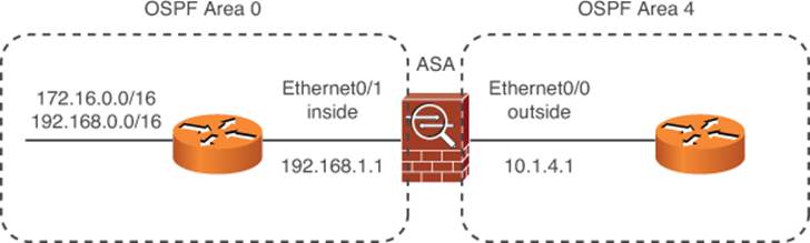
Figure 4-21. Example OSPF Scenario
The ASA is configured to allow any inside subnet except 192.168.99.0/24 to be advertised into OSPF area 4 on the outside.
You can use ASDM to configure the OSPF. Navigate to Configuration > Device Setup > Routing > OSPF > Setup. On the Process Instances tab, you can enable OSPF and configure the OSPF instance with a process ID, as shown in Figure 4-22. OSPF is identified by a unique, arbitrary process ID. Up to two separate OSPF processes can be run on a firewall. This allows each process to exchange routing information independently, although a single routing table is maintained in the firewall. (The process ID is only locally significant; it is not passed or matched among routers and firewalls.)
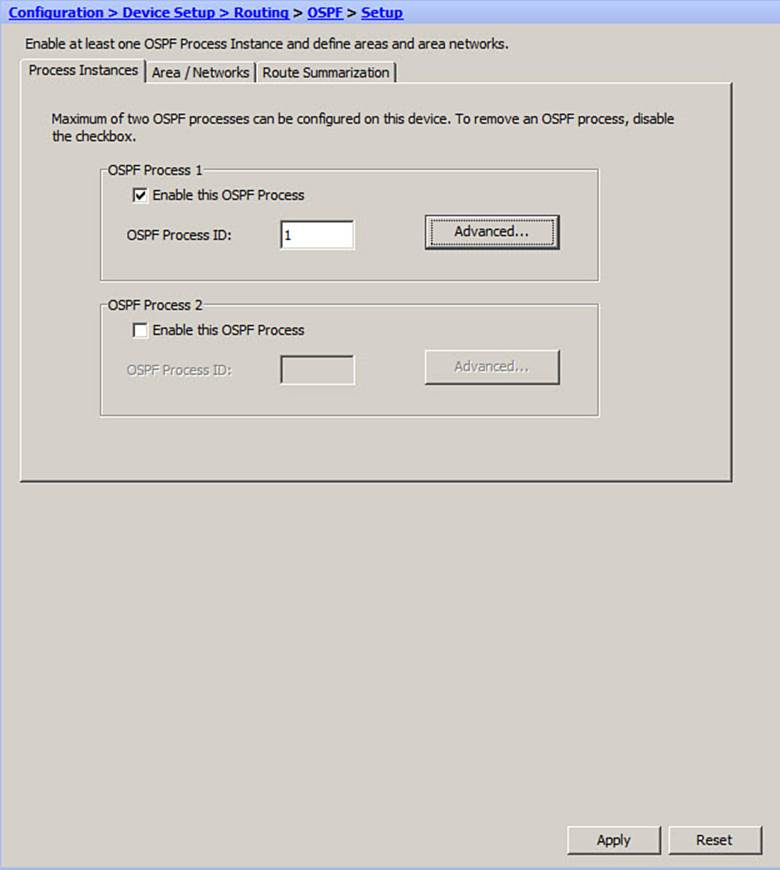
Figure 4-22. Configuring the OSPF Process in ASDM
By clicking the Advanced button, you can set the router ID, configure OSPF logging, adjust the administrative distance, tune the OSPF timers, and enable default information originate.
On the Area/Networks tab, you can define the IP networks in which OSPF will participate. Figure 4-23 shows the 192.168.1.0/24 network being added as OSPF area 0. Once all of the directly connected networks have been added, you can click the Route Summarization tab to add any summary routes that should be advertised.
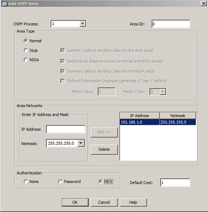
Figure 4-23. Configuring OSPF Networks in ASDM
Next, you can choose Routing > OSPF > Filtering to configure any route filtering. You can click the Add button to add a new rule to the route filter. Specify the OSPF process number and OSPF area where the rule will be applied. You can also specify the IP network, filter direction, filter sequence number, and action. In Figure 4-24, network 172.16.0.0/16 is permitted by the filter.
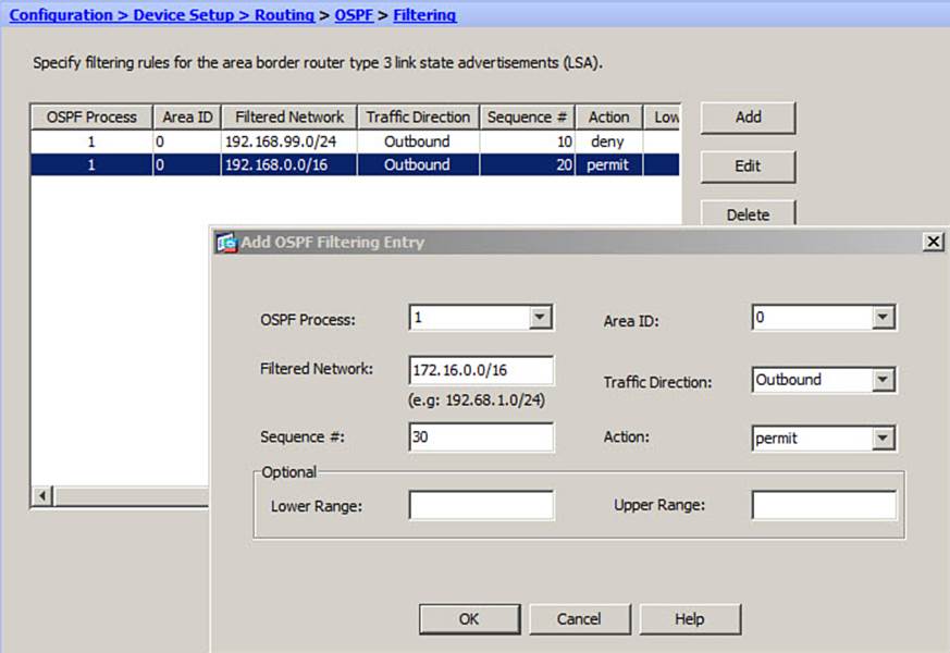
Figure 4-24. Configuring OSPF Route Filtering in ASDM
You can choose Routing > OSPF > Interface to configure any interface-related parameters. For example, Figure 4-25 shows the outside interface being configured for MD5 authentication, with key ID 1 and key string myoutsidekey.
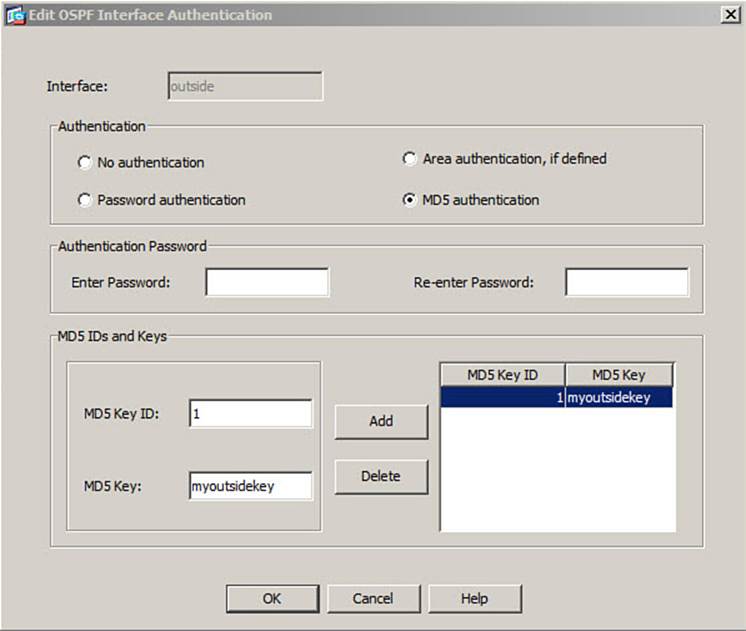
Figure 4-25. Configuring OSPF Interface Parameters in ASDM
If you have configured another routing information source besides OSPF, you might want to configure route redistribution. You can do this by choosing Routing > OSPF > Redistribution, although the example scenario does not require redistribution.
OSPF is a complex, robust routing protocol. This means that it is flexible but can be tedious to configure, especially through the CLI. You can configure OSPF by using the following steps:
Step 1. Define an OSPF process:
ciscoasa(config)# router ospf pid
Step 2. Configure Advanced options.
By default, OSPF uses the highest IP address defined on any ASA interface as the router ID, used to identify the ASA in any OSPF exchanges with neighboring routers. You can override that by using the following command:
ciscoasa(config-router)# router-id ip_address
By default, an ASA generates logging messages to indicate when an OSPF neighbor adjacency goes up or down. You can change the logging behavior with the following command:
ciscoasa(config-router)# log-adj-changes [detail]
An ASA can advertise a default route as an external route by using the following command:
ciscoasa(config-router)# default-information originate [always]
[metric value] [metric-type {1 | 2}] [route-map name]
If you use the always keyword, a default route is advertised even if one has not been specifically configured. The route is advertised with a metric of value (0 to 16777214; the default is 1). By default, the route is advertised as an external Type 2 route (metric-type 2); you can override that behavior with the metric-type keyword. You can also configure a route map separately and apply it with the route-map keyword to filter the default route that is advertised.
By default, all OSPF routes have an administrative distance of 110. This is consistent with Cisco routers. You can use the following command to change the distance values:
ciscoasa(config-router)# distance ospf [intra-area d1] [inter-area d2]
[external d3]
Use the intra-area keyword to set routes within an OSPF area to d1, the inter-area keyword to set routes from one area to another to d2, and the external keyword to set routes from another routing protocol into the OSPF area to d3.
You can adjust the OSPF route calculation timers with the following command:
ciscoasa(config-router)# timers {spf spf_delay spf_holdtime | lsa-group-
pacing seconds}
The OSPF process will wait a delay time of spf_delay (default 5 sec) after receiving a topology change before starting the SPF calculation. OSPF will wait spf_holdtime (default 10 sec) between two consecutive calculations. You can also tune the calculation process with the lsa-group-pacing keyword. LSAs are gathered and processed at regular intervals (the default is 240 sec).
Step 3. Associate a network with an OSPF area:
ciscoasa(config-router)# network ip_address netmask area area_id
The OSPF process exchanges routing information on any ASA interface that falls within the address range specified here. As well, the network assigned to that interface is advertised by OSPF.
An OSPF area can be referred to by a decimal number or by a subnet notation. For example, area 5 can also be written as 0.0.0.5, area 100 as 0.0.0.100, and area 0 as 0.0.0.0. Using subnet notation for OSPF areas is handy when you have a specific subnet by itself in one area. Also remember that OSPF must have one backbone area, called area 0 or area 0.0.0.0.
Step 4. Authenticate OSPF neighbors in an area.
OSPF peers can authenticate information from each other using cleartext passwords or MD5 hash values, although using MD5 is a best practice. If authentication is enabled on one device, it must be enabled on all the neighboring devices in the same area. Enable authentication with the following command:
ciscoasa(config-router)# area area_id authentication [message-digest]
In addition, the actual authentication keys must be defined on each OSPF interface with the following commands:
ciscoasa(config)# interface interface
ciscoasa(config-if)# ospf message-digest-key key-id md5 key
ciscoasa(config-if)# ospf authentication message-digest
If authentication has been enabled for an OSPF area, you must also set up the authentication key on each interface in that area. You can define several keys by repeating the command. Each key is known by a key-id index, ranging from 1 to 255. The actual MD5 key is a string of up to 16 text characters.
The key string found at index key-id on one router or firewall must match the same key at key-id on all other neighboring routers or firewalls. You can change the keys periodically by defining a new key at a new key-id index. The old key continues to be used even though a new one has been defined. As soon as all neighboring routers have the new key too, OSPF rolls over and uses the new authentication key. At that time, you should remove the old MD5 keys with the no ospf message-digest key-id interface configuration command.
Step 5. Optionally, define a special case area.
You can define an OSPF area as a stub area if there is only one path into and out of the area. All OSPF neighbors in a stub area must configure it as a stub. You can use the following command to configure a stub area:
ciscoasa(config-router)# area area_id stub [no-summary]
Include the no-summary keyword to create a totally stubby area, where OSPF prevents the introduction of any external or interarea routes into the stub area.
You can configure an area as a not-so-stubby area (NSSA), where external routes are allowed to be transported through. In the following command, you can use the no-redistribution keyword on an ABR ASA if you want external routes to be redistributed only into normal areas, but not into any NSSAs:
ciscoasa(config-router)# area area_id nssa [no-redistribution]
[default-information-originate [metric-type 1 | 2] [metric
metric_value]]
Use the default-information-originate keyword to generate a default route into the NSSA. If that is used, you can define the default route as an external route type 1 (route cost plus the internal OSPF metric) or 2 (route cost without the internal OSPF metric). You can also specify a default route metric.
Step 6. Optionally, configure route filtering.
If an ASA is configured as an ABR, it sends type 3 LSAs between the areas it touches. This means that the networks in each area are advertised into other areas. Naturally, you wouldn’t want private networks to be advertised toward the outside, for security and network translation reasons. You can define a prefix list to filter routes that are advertised:
ciscoasa(config)# prefix-list list_name [seq seq_number] {permit | deny}
prefix/len [ge min_value] [le max_value]
Note
Unlike RIPv2 and EIGRP, OSPF does not use a distribute list to filter routes that are advertised. This is because every OSPF router maintains its own snapshot of the entire routing topology.
The prefix list is given a text string name. You can repeat this command to add more conditions to the list. By default, prefix list entries are automatically numbered in increments of 5, beginning with sequence number 5. Routes are evaluated against the prefix list entries in sequence, starting with the lowest defined sequence number. By giving a specific sequence number here, you can wedge a new statement between two existing ones.
A prefix list entry can either permit or deny the advertisement of matching routes in type 3 LSAs. A prefix list entry matches an IP route address against the prefix (a valid IP network address) and len (the number of leftmost bits in the address) values. The ge (greater than or equal to a number of bits) and le (less than or equal to a number of bits) keywords can also be used to define a range of the number of prefix bits to match. A range can provide a more specific matching condition than the prefix/len values alone.
For example, to permit advertisements of routes with a prefix of 172.16.0.0/16, but having any mask length between 16 and 24 bits, you could use the following command:
ciscoasa(config)# prefix-list LIST permit 172.16.0.0/16 ge 16 le 24
Next, apply the prefix list to filter LSAs into or out of an area with the following command:
ciscoasa(config-router)# area area_id filter-list prefix list_name
[in | out]
If you want to suppress advertisement of an internal network, you can apply the prefix list for LSAs going in or out of the area area_id. This means you can stop the advertisements from leaving a private area by applying the prefix list to the private area_id in the out direction. Or you can filter the advertisements on the public area area_id side in the in direction.
Step 7. Summarize routes between areas.
An ABR can reduce the number of routes it sends into an area by sending a summary address instead. The summary address is sent in place of any route that falls within the range defined by ip_address and netmask in the following command:
ciscoasa(config-router)# area area_id range ip_address netmask
[advertise | not-advertise]
The advertise keyword is assumed by default; if you don’t want the summary address advertised, use the not-advertise keyword.
Step 8. Optionally, redistribute routes from another source.
When a firewall redistributes routes from any other source into OSPF, it automatically becomes an ASBR by definition. You can (and should) use a route map to control which routes are redistributed into OSPF. You can define a route map with the following command:
ciscoasa(config)# route-map map_tag [permit | deny] [seq_num]
The route map named map_tag (an arbitrary text string) either permits or denies a certain action. You can repeat this command if you need to define several actions for the same route map. In this case, you should assign a sequence number seq_num to each one.
Use the permit keyword to define an action that redistributes routes into OSPF. The deny keyword defines an action that is processed but does not redistribute routes.
Next, define one or more matching conditions with the match command. If you configure multiple match statements, all of them must be met. Table 4-5 lists the possible match commands.
Table 4-5. Route Map match Commands
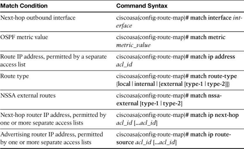
For each match in a route map, you can configure one or more attributes to be set by using the set commands listed in Table 4-6.
Table 4-6. Route Map set Commands
Finally, you can use the following command to redistribute routes from another source into the OSPF process:
ciscoasa(config-router)# redistribute {static | connected
| rip | eigrp as_num} [metric metric_value] [metric-
type metric_type] [route-map map_name] [tag tag_value] [subnets]
Either static routes (configured with the route command), connected routes (subnets directly connected to firewall interfaces), or routes learned through RIPv2 or EIGRP can be redistributed into the OSPF process. Use the connected keyword only when you have ASA interfaces that aren’t configured to participate in OSPF. Otherwise, OSPF automatically learns directly connected interfaces and their subnets from the OSPF configuration.
If you configure a route map for redistribution, you should specify it with the route-map keyword. If the route-map keyword is omitted, all routes are distributed.
You can also set fixed values for the OSPF metric_value (0 to 16777214), the metric_type (internal, external, type-1, or type-2), and the route tag value (an arbitrary number that can be used to identify and match routes on other ASBRs) for all routes, not just ones matched by a route map.
By default, only routes that are not subnetted (classful routes) are redistributed into OSPF unless the subnets keyword is given.
Because an ASA can have two independent OSPF processes running, you can also redistribute routes from one OSPF process into the other. You can use the following command to identify the source OSPF process ID:
ciscoasa(config-router)# redistribute ospf pid [match
{internal | external [1 | 2] | nssa-external [1 | 2]}]
[metric metric_value] [metric-type metric_type]
[route-map map_name] [tag tag_value] [subnets]
If you do not use a route map, you can still redistribute only routes with specific metric types by using the match keyword. The types include internal (internally generated), external (OSPF type 1 or 2), and nssa-external (OSPF type 1 or 2 coming into an NSSA).
You can use the commands listed in Example 4-7 to build the example scenario.
Example 4-7. Configuration Commands Used for the Figure 4-21 Scenario
ciscoasa(config)# interface ethernet0
ciscoasa(config-if)# nameif outside
ciscoasa(config-if)# security-level 0
ciscoasa(config-if)# ip address 10.1.4.1 255.255.255.0
ciscoasa(config-if)# ospf authentication message-digest
ciscoasa(config-if)# ospf message-digest-key 1 md5 myoutsidekey
ciscoasa(config-if)# exit
ciscoasa(config)# interface ethernet1
ciscoasa(config-if)# nameif inside
ciscoasa(config-if)# security-level 100
ciscoasa(config-if)# ip address 192.168.1.1 255.255.255.0
ciscoasa(config-if)# ospf authentication message-digest
ciscoasa(config-if)# ospf message-digest-key 1 md5 myinsidekey
ciscoasa(config-if)# exit
ciscoasa(config)# prefix-list InsideFilter 10 deny 192.168.99.0/24
ciscoasa(config)# prefix-list InsideFilter 20 permit 192.168.0.0/16
ciscoasa(config)# prefix-list InsideFilter 30 permit 172.16.0.0/16
ciscoasa(config)# router ospf 1
ciscoasa(config-router)# network 192.168.1.0 255.255.255.0 area 0
ciscoasa(config-router)# network 10.1.4.0 255.255.255.0 area 4
ciscoasa(config-router)# area 0 filter-list prefix InsideFilter out
ciscoasa(config-router)# exit
Verifying the ASA Routing Table
You can display the routes in an ASA’s routing table in ASDM by navigating to Monitoring > Routing > Routes. Figure 4-26 shows the routing table, which lists the directly connected and static routes.
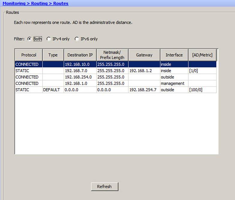
Figure 4-26. Displaying the Routing Table in ASDM
Through the CLI, you can verify the routes in an ASA’s routing table by using the show route command. The output shows routes learned by any possible means, whether directly connected, through static configuration, or through a dynamic routing protocol.
Example 4-8 lists the contents the routing table on an ASA that has only directly connected and static routes.
Example 4-8. Displaying the Routing Table Contents with show route
ciscoasa# show route
Codes: C - connected, S - static, I - IGRP, R - RIP, M - mobile, B - BGP
D - EIGRP, EX - EIGRP external, O - OSPF, IA - OSPF inter area
N1 - OSPF NSSA external type 1, N2 - OSPF NSSA external type 2
E1 - OSPF external type 1, E2 - OSPF external type 2, E - EGP
i - IS-IS, L1 - IS-IS level-1, L2 - IS-IS level-2, ia - IS-IS inter area
* - candidate default, U - per-user static route, o - ODR
P - periodic downloaded static route
Gateway of last resort is 192.168.254.7 to network 0.0.0.0
C 192.168.10.0 255.255.255.0 is directly connected, inside
S 192.168.7.0 255.255.255.0 [1/0] via 192.168.1.2, inside
C 192.168.254.0 255.255.255.0 is directly connected, outside
C 192.168.1.0 255.255.255.0 is directly connected, management
S* 0.0.0.0 0.0.0.0 [100/0] via 192.168.254.7, outside
ciscoasa#
Notice the legend of route codes in the first several lines. Directly connected routes are displayed with a C code in the left column. Static routes are displayed with an S code. This ASA has one static route for a subnet located on the inside interface. It also has one static default route pointing toward a next-hop router on the outside interface.
Static routes and routes learned from a dynamic routing protocol are shown with square brackets containing two values. The first value is the administrative distance, and the second value is the metric derived or used by the routing protocol.
Notice that the default route in Example 4-8 has an administrative distance of 100, not the normal distance of 1 that a static route should have by default. In this case, static route tracking is involved; the tracked route must be down, so the backup (less preferable, greater distance) route is active in the routing table. You can display all the configured static routes with the show running-config route command, as demonstrated in Example 4-9.
Example 4-9. Displaying Configured Static Routes
ciscoasa# show running-config route
route outside 0.0.0.0 0.0.0.0 192.168.254.2 1 track 1
route outside 0.0.0.0 0.0.0.0 192.168.254.7 100
route inside 192.168.7.0 255.255.255.0 192.168.1.2 1
ciscoasa#
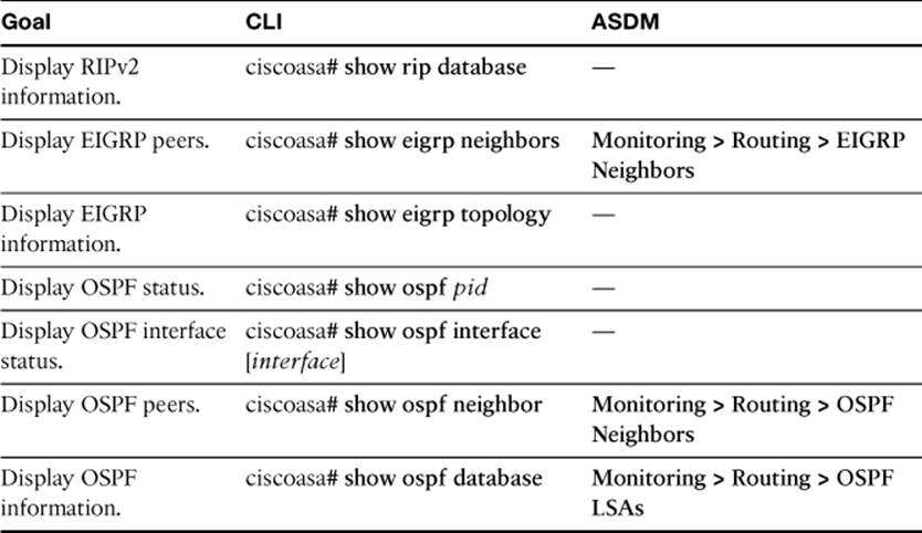
You can use the EXEC commands listed in Table 4-7 to verify dynamic routing protocol operation.
Table 4-7. Useful Commands for Verifying Dynamic Routing Protocols
Exam Preparation Tasks
As mentioned in the section, “How to Use This Book,” in the Introduction, you have a couple of choices for exam preparation: the exercises here, Chapter 17, “Final Preparation,” and the exam simulation questions on the CD-ROM.
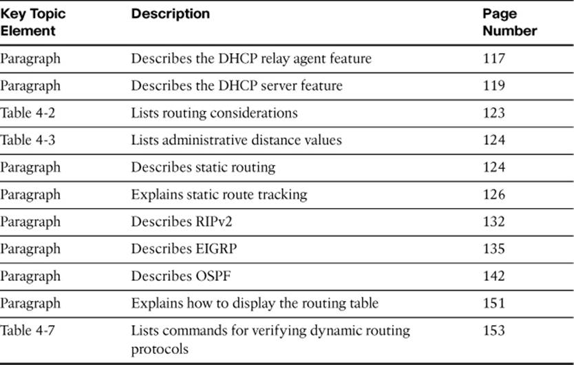
Review All Key Topics
Review the most important topics in this chapter, noted with the Key Topic icon in the outer margin of the page. Table 4-8 lists a reference of these key topics and the page numbers on which each is found.
Table 4-8. Key Topics for Chapter
Define Key Terms
Define the following key terms from this chapter and check your answers in the glossary:
DHCP relay
DHCP server
static route
RIPv2
EIGRP
OSPF
administrative distance
SLA monitor
Command Reference to Check Your Memory
This section includes the most important configuration and EXEC commands covered in this chapter. It might not be necessary to memorize the complete syntax of every command, but you should be able to remember the basic keywords that are needed.
To test your memory of the commands, cover the right side of Tables 4-9 through 4-13 with a piece of paper, read the description on the left side, and then see how much of the command you can remember.
Table 4-9. Commands Related to DHCP Service Configuration and Verification
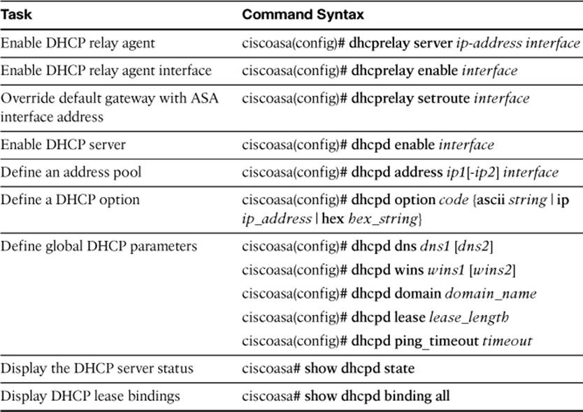
Table 4-10. Commands Related to Static Route Configuration and Verification
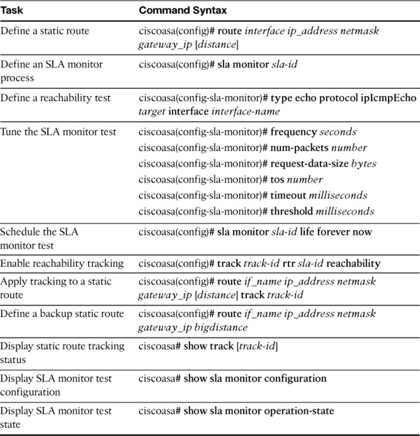
Table 4-11. Commands Related to RIPv2 Configuration and Verification
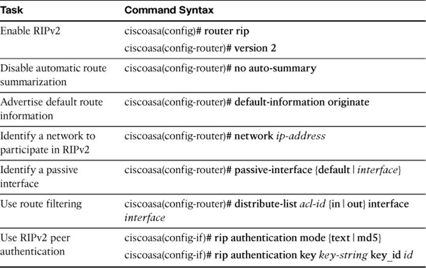
Table 4-12. Commands Related to EIGRP Configuration and Verification
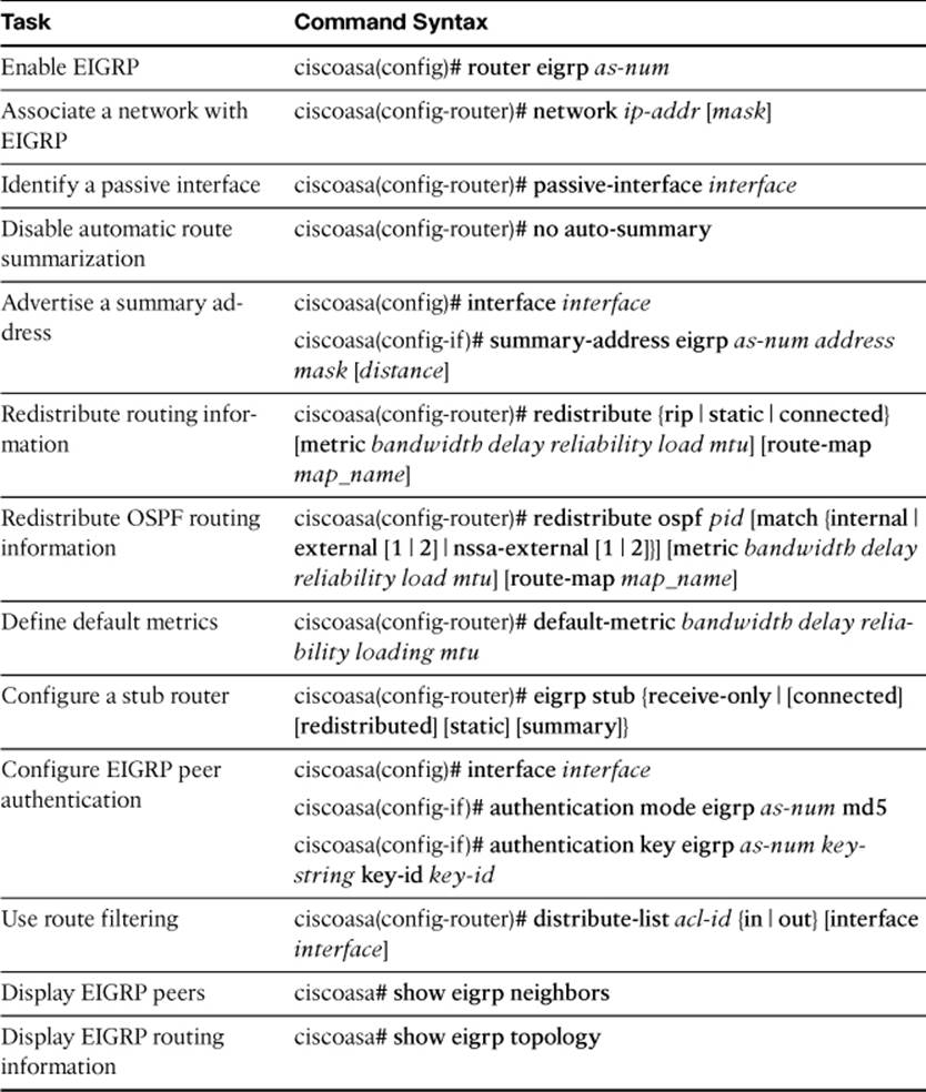
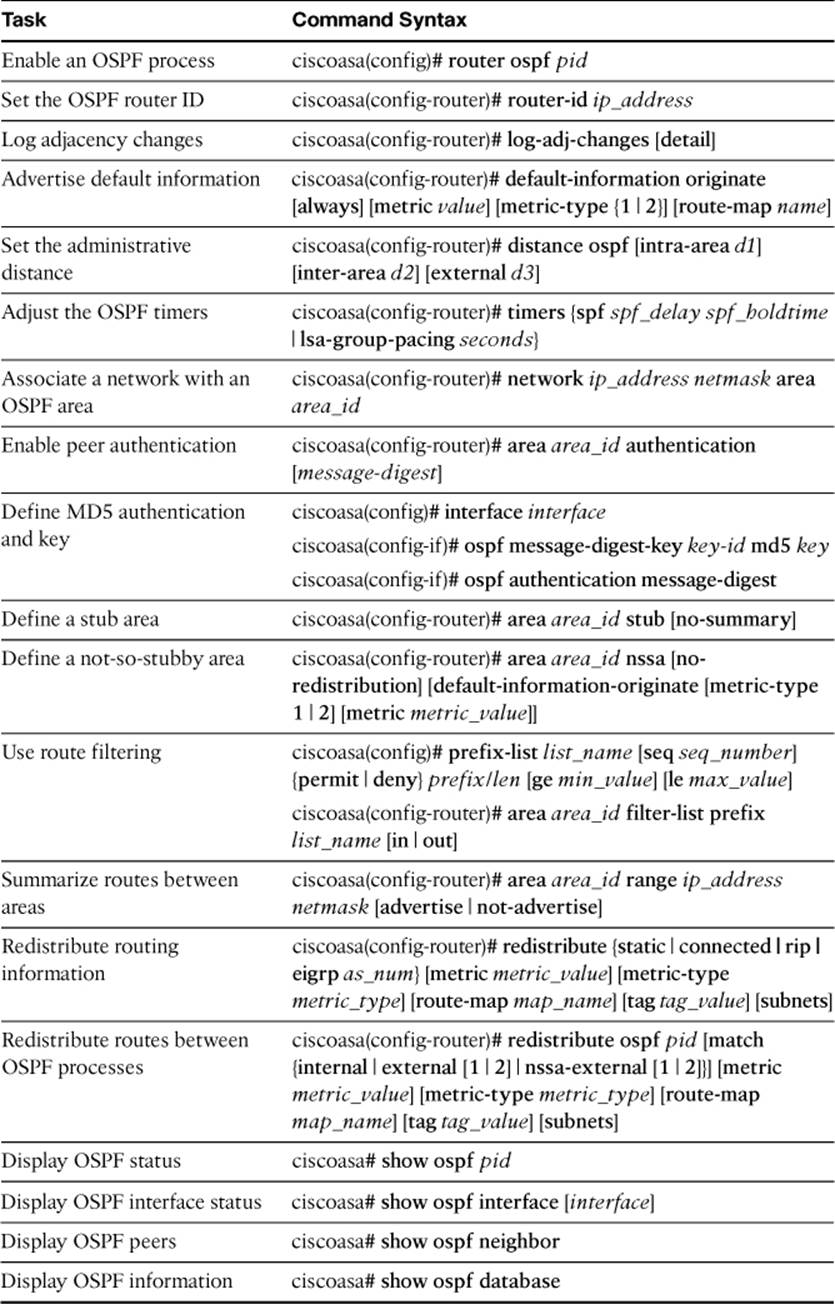
Table 4-13. Commands Related to OSPF Configuration and Verification
The FIREWALL exam focuses on practical, hands-on skills that are used by a networking professional. Therefore, you should be able to identify the commands needed to configure and test an ASA feature.
All materials on the site are licensed Creative Commons Attribution-Sharealike 3.0 Unported CC BY-SA 3.0 & GNU Free Documentation License (GFDL)
If you are the copyright holder of any material contained on our site and intend to remove it, please contact our site administrator for approval.
© 2016-2026 All site design rights belong to S.Y.A.