CCNP Security FIREWALL 642-618 Official Cert Guide (2012)
Chapter 5. Managing a Cisco ASA
This chapter covers the following topics:
• Basic Device Settings: This section describes configuration of basic device settings, such as hostname, domain, enable password, and Telnet password.
• Configuring DNS Resolution: This section describes configuration of a Domain Name System (DNS) server group.
• File System Management: This section describes how to manage the file system in flash memory on a Cisco ASA, including where the ASA keeps its configuration, system software, and auxiliary files.
• Managing Software and Feature Activation: This section describes how to manage the activation of features within the operating system of an ASA and how to change the activation key of the security appliance.
• Configuring Management Access: This section describes how to configure an ASA for remote management, using Telnet, Secure Shell (SSH), a dedicated out-of-band interface, or HTTP over SSL/TLS (HTTPS) using Cisco Adaptive Security Device Manager (ASDM).
• Controlling Management Access with AAA: This section describes how to configure an ASA to perform authentication, authorization, and accounting, using the local database, a remote AAA server, or a combination of the two.
• Configuring Monitoring Using SNMP: This section describes how to configure an ASA to send SNMP traps to a management console for monitoring purposes.
• Troubleshooting Remote Management Access: This section describes common methods for troubleshooting remote management access problems.
• Cisco ASA Password Recovery: This section describes how to perform password recovery on an ASA to regain access after the loss of all administrative passwords.
A Cisco Adaptive Security Appliance (ASA), like any other networking device, offers several ways for an administrative user to connect to and interact with it. The ASA supports in-band management (using a traffic-passing interface) and out-of-band management (using a dedicated management-only interface). You can access the ASA using Telnet, Secure Shell (SSH), and HTTPS protocols (after the ASA is configured to allow such access), as well as SNMP (versions 1, 2c, and 3) for monitoring purposes. You can achieve highly granular control over such access using authentication, authorization, and accounting (AAA) features of the ASA.
“Do I Know This Already?” Quiz
The “Do I Know This Already?” quiz allows you to assess whether you should read this entire chapter thoroughly or jump to the “Exam Preparation Tasks” section. If you are in doubt about your answers to these questions or your own assessment of your knowledge of the topics, read the entire chapter. Table 5-1 lists the major headings in this chapter and their corresponding “Do I Know This Already?” quiz questions. You can find the answers in Appendix A, “Answers to the ‘Do I Know This Already?’ Quizzes.”
Table 5-1. “Do I Know This Already?” Section-to-Question Mapping
Caution
The goal of self-assessment is to gauge your mastery of the topics in this chapter. If you do not know the answer to a question or are only partially sure of the answer, you should mark that question as wrong for purposes of the self-assessment. Giving yourself credit for an answer you correctly guess skews your self-assessment results and might provide you with a false sense of security.
1. Which two commands establish a fully qualified domain name (FQDN) that can be used by an ASA for certificate generation? (Choose two answers.)
a. crypto ca trustpoint ASA-Self-Signed
b. hostname FIREWALL
c. ip domain-name CISCOPRESS.CCNP
d. domain-name CISCOPRESS.CCNP
2. Why would you issue the command delete FSCK*.REN?
a. To delete “junk” files created by the ASA during a file system integrity check
b. Because your ASA is running out of memory blocks
c. To delete the autogenerated backup configuration files, which are named FSCKx.REN, where x is a number, beginning at 0 and incrementing to 4
d. To delete all directories in flash named FSCKx.REN, where x is one or more characters
3. Which of the following are displayed by using the show version command? (Choose all that apply.)
a. The device flash BIOS serial number
b. The current value of the config-register
c. The running activation key
d. The number of active security contexts
e. The type and amount of system flash memory
4. When does the ASA generate a self-signed X.509 certificate used to authenticate the device during ASDM use?
a. On initial boot only, the ASA generates a persistent self-signed certificate.
b. Upon each boot, the ASA generates a self-signed certificate, but you can create a persistent self-signed certificate.
c. After you delete and regenerate the RSA key pair, upon the next boot only, the ASA generates a persistent self-signed certificate.
d. The ASA does not use a certificate for ASDM access.
5. Which of the following is not a supported server type for AAA?
a. TACACS+
b. Kerberos
c. LDAP
d. SQL
e. SecurID
f. All of these are supported server types.
6. What is the default privilege level for users created with the username command?
a. 0
b. 1
c. 2
d. 5
e. 15
f. There is no default privilege level; you must explicitly assign one.
7. Where in Cisco Secure ACS are Shell Command Authorization Sets created?
a. Administration Control
b. Network Access Profiles
c. Group Setup > TACACS+
d. Shared Profile Components
e. Shell Command Authorization Sets are not created in ACS; they are created locally on the ASA.
8. Which of the following SNMP trap types are enabled by default? (Choose all that apply.)
a. Link Up
b. Link Down
c. Cold Start
d. Authentication
e. Session Threshold Exceeded
f. All of the answers are correct.
9. What would happen during the initiation of an SSH connection that would generate the following system log message?
%ASA-3-315011: SSH session from 192.168.1.8 on interface management for user ""
disconnected by SSH server, reason: "Internal error" (0x00)
a. The user’s SSH client does not support SSH version 2.
b. The user is attempting an SSH version 2 connection, and the ASA is configured to accept version 1 only.
c. The ASA does not have an RSA key pair configured.
d. The ASA is not configured to accept SSH connections from the indicated source address.
10. What value do you set the config-register to in order to perform password recovery?
a. 0x01
b. 0x02
c. 0x41
d. 0x24
e. 0xFF
Foundation Topics
To properly integrate a Cisco ASA into your local network, you need to be able to configure the ASA with appropriate information about itself and the local environment. Before you can perform these basic management tasks, you will need to gather information about the local network environment into which the ASA will be integrated, such as the local Domain Name System (DNS) servers, Network Time Protocol (NTP) servers (and, if using authenticated NTP, their authentication credentials), file servers that are used by network devices to store files remote to themselves, and syslog servers for logging event information. Additionally, you will need to know which features are required for the ASA to satisfy the security requirements of your business. This information is necessary in order to choose the correct software image and activation key.
The FIREWALL exam focuses on practical, hands-on skills that are used by a networking professional. You will be expected to be familiar with how to configure various features either from the ASDM GUI or from the CLI, and to be able to use either for verification and troubleshooting. This being the case, this book will show the use of both tools, primarily configuring an ASA using ASDM, and recapping the equivalent CLI commands for each section.
Basic Device Settings
An ASA can operate with default settings for many items. For instance, it is possible to secure a network and pass traffic to and from the Internet without configuring items like the hostname, domain name, enable password, and local time parameters. However, if you want to provide the ASA with protection from unauthorized access, allow Secure Shell (SSH) management, write syslog messages with correct time stamps, register your device for a digital certificate that properly identifies it as an asset of your organization, and otherwise integrate the ASA into your local environment, you will have to perform some or all of the following tasks:
• Configure device identify (host and domain name)
• Configure basic authentication (enable and Telnet passwords)
Configuring Device Identity
Providing the ASA with information identifying itself is more than just a matter of seeing a unique device name in a CLI prompt. The device hostname and domain name together construct the fully qualified domain name (FQDN) of the ASA, which is used to generate a self-signed digital certificate upon boot. This certificate is used when authenticating the device for HTTPS (ASDM) management and can be used, if a certificate from another certificate authority (CA) is not configured, to authenticate the ASA for IP Security (IPsec) or Secure Sockets Layer (SSL) Virtual Private Network (VPN) operations (a certificate from a public CA is highly preferable). The hostname can also be sent by the ASA as part of syslog messages, to make it easier to identify their source, and can be registered in local DNS records, if so desired.
You can configure both hostnames and domain names (each limited to 63 characters maximum) within ASDM, but the following examples use the CLI to demonstrate a change in the command prompt. To configure the hostname of the ASA, use the hostname command from global configuration mode, as demonstrated here:
ciscoasa(config)# hostname FIREWALL
FIREWALL(config)#
Notice that the ASA changes the command prompt to show the newly configured hostname.
To complete the FQDN, a domain name is needed to complement the hostname. This is optional under most circumstances, but it is necessary when deploying any kind of X.509 digital certificates (which can be used for HTTPS access, SSL VPN, or IPsec VPN). To configure a domain name for the ASA, use the domain-name command from global configuration mode:
FIREWALL(config)# domain-name CISCOPRESS.CCNP
Note
The domain name CISCOPRESS.CCNP is used strictly for illustrative purposes, as no such top-level domain exists.
Configuring Basic Authentication
By default, a Cisco ASA requires no password to enter privileged EXEC (enable) mode. Because initial access to the console port necessitates physical access, this is understandable. However, if an ASA is going to enter production, it is unacceptable to provide access without requiring at least basic authentication. Also, although an ASA does require a password for remote Telnet access, it is set to “cisco” by default, which should be changed before the ASA enters a production network. By default, this password is also used for SSH access (with the username being “pix”) in the absence of AAA authentication being configured. It is therefore critical to configure a strong password or configure AAA.
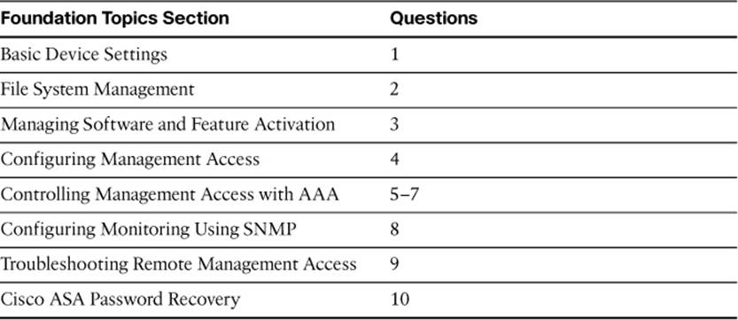
The hostname, domain name, enable password, and Telnet password are all configured within the same ASDM window. After launching ASDM, navigate to Configuration > Device Setup > Device Name/Password to make changes to these settings, as demonstrated in Figure 5-1.
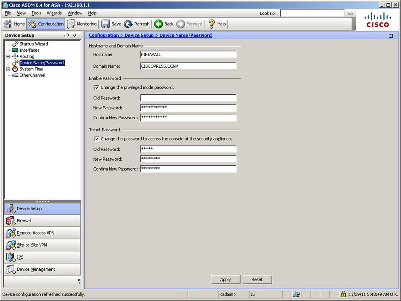
Figure 5-1. Configuring Identity and Basic Passwords in ASDM
Figure 5-1 shows the ASA with the hostname and domain name already set. To change the enable password, check the Change the Privileged Mode Password check box. Because there is no enable password on the device prior to this, leave the Old Password field under Enable Password blank and enter the new password twice, the second time to ensure you entered it correctly. To change the Telnet password, first check the Change the Password to Access the Console of the Security Appliance check box. Because the ASA has a default Telnet password, you need to entercisco in the Old Password field under Telnet Password, and then enter a new password twice, to set a new password. Click Apply to send the changes to the ASA.
The CLI commands generated by the changes made are as follows:
enable password sH5punHtqaLcqj3E level 15 encrypted
passwd w8iLGf/6z5hYvVsP encrypted
If you are configuring the ASA from the CLI, you can enter these commands directly in global configuration mode.

If you are configuring from the CLI, use the enable password command to set the privileged mode password. The ASA automatically converts the password to an MD5 hash when storing it. The keyword encrypted at the end of output line specifies that the password is shown in encrypted form (actually, an MD5 hash) rather than in plain text. You would not type this when configuring the enable password, but if you want to copy this password to another ASA, copy the entire line, including this keyword, to enable the new ASA to recognize that you are not entering a plain-text password.
Note
If entering the enable password command from the CLI in cleartext, simply enter the command as enable password string level privilege_level. The absence of the encrypted keyword is interpreted by the ASA as meaning that the string represents the new password in plain text. Subsequent show output, however, always displays the password in it MD5 hashed form.
Use the passwd (or password) command to set the Telnet password of the ASA. The ASA automatically converts the password to an MD5 hash when storing it.
Note
In the absence of AAA authentication (discussed later in this chapter), the Telnet password is also used for SSH authentication, coupled with the username “pix.”
The configured enable password is used for access to Cisco Adaptive Security Device Manager (ASDM) in the absence of other HTTP authentication (covered later in the section, “Controlling Management Access with AAA”). Although you have set a Telnet password, accessing the ASA with Telnet is not currently possible. Enabling Telnet access is covered in the section, “Configuring Remote Access Using Telnet.”
When you create passwords, write them down and store them in a manner consistent with your site security policy. You cannot view these passwords using show commands on the ASA because they are stored as Message Digest 5 (MD5) hashes. The show running-config command lists the encrypted form of the passwords.
Verifying Basic Device Settings
Device identity configuration can be verified using two commands, show hostname and show running-config domain-name (there is no show domain-name command), as demonstrated in Example 5-1.
Example 5-1. Displaying Device Identity
FIREWALL# show hostname
FIREWALL
FIREWALL# show running-config domain-name
CISCOPRESS.CCNP
The enable password can be verified by exiting privileged mode and then re-entering it, as demonstrated in Example 5-2.
Example 5-2. Verifying Basic Authentication
FIREWALL# disable (or logout or exit)
FIREWALL> enable
Password: ***********
FIREWALL#
Configuring DNS Resolution
Because people have trouble remembering complex numbers, trying to remember multiple IP addresses would be impractical. Fortunately, the Domain Name System (DNS) enables you to use logical names for IP addresses by resolving those names to the IP addresses they represent.
Configuring DNS Server Groups
To configure the ASA to use DNS for name-to-address resolution, you create or modify the default DNS server group. To do so using ASDM, navigate to Configuration > Device Management > DNS > DNS Client, as shown in Figure 5-2.
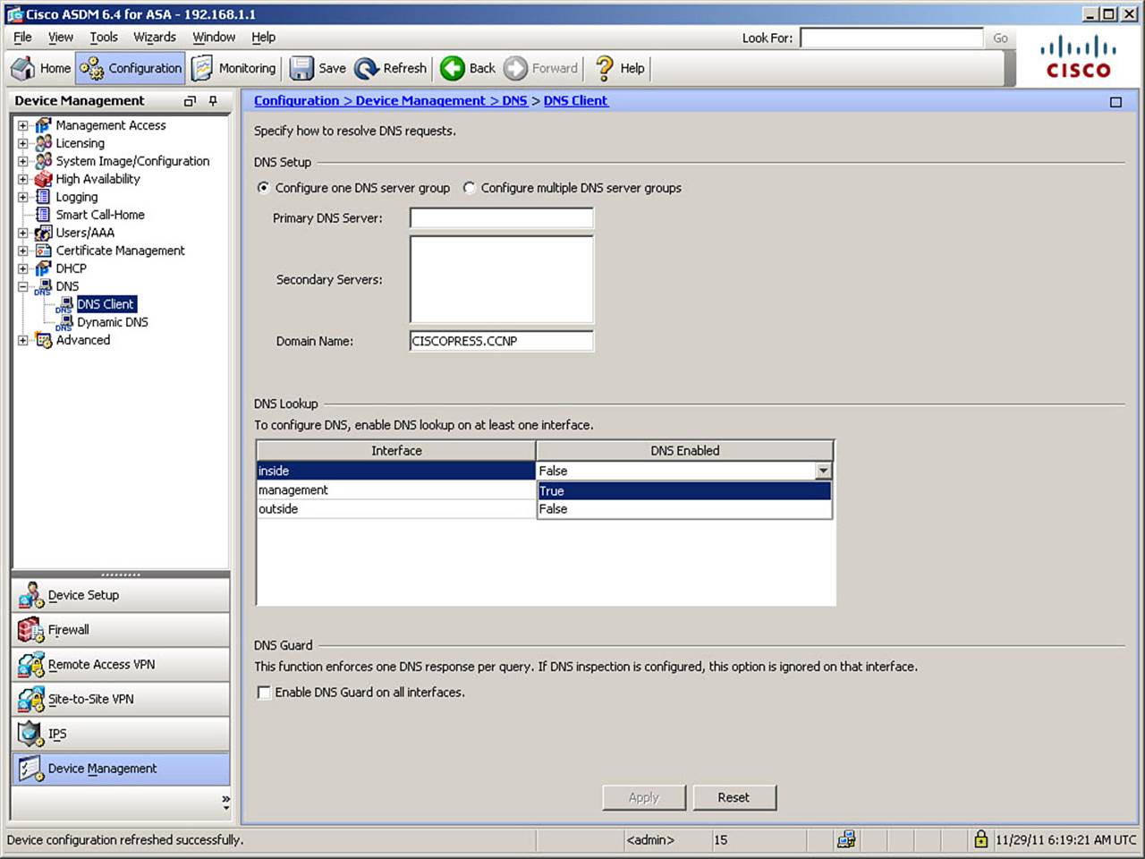
Figure 5-2. Activating DNS on an Interface
In the DNS Lookup area, as shown in Figure 5-2, you must enable DNS on at least one interface before you can add a DNS server to a DNS server group. You should enable DNS lookup on all interfaces from which the configured DNS servers are reachable. In Figure 5-3, DNS has been enabled on the inside interface, and you are ready to define specific DNS servers.
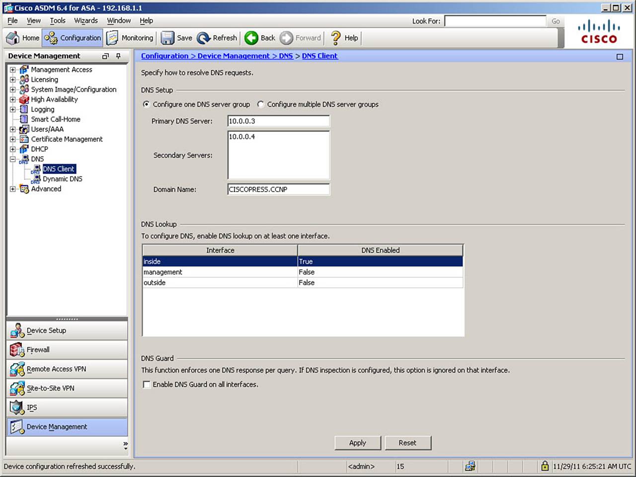
Figure 5-3. Defining DNS Server Group Members
After DNS is enabled on at least one interface, you can configure a primary DNS server and any secondary DNS servers you want the ASA to use. In Figure 5-3, a primary DNS server (IP address 10.0.0.3) and one secondary DNS server (IP address 10.0.0.4) are configured. Note that the domain name suffix is assumed to be that configured earlier, CISCOPRESS.CCNP. If you enter a different domain name suffix when configuring the default DNS server group, it will also change the ASA’s domain name. Optionally, you can enable DNSGuard on all interfaces to enforce a one-to-one balance of DNS replies to DNS queries to guard against DNS spoofing attacks. If you use DNS servers on networks outside your domain of control, this is highly recommended.
Note
The explicit definition of DNS servers is required in order to use the Botnet Traffic Filtering function, as well as if you need the ASA to be able to resolve URLs when using clientless SSL VPN.
The CLI commands generated by the changes made are as follows:
dns domain-lookup inside
dns server-group DefaultDNS
name-server 10.0.0.3
name-server 10.0.0.4
If you are configuring the ASA from the CLI, you can enter these commands in global configuration mode.
The dns domain-lookup command enables the ASA DNS client to query DNS servers over a particular interface. The dns server-group command defines a set of DNS resolver settings, including server IP addresses and the domain suffix used in lookups that lack a FQDN (for example, typing ROUTER instead of ROUTER.CISCOPRESS.CCNP). The DefaultDNS server group is the set of DNS settings the ASA uses by default.
Verifying DNS Resolution
There are a variety of ways to verify DNS functionality. Perhaps the easiest way is to simply ping a destination by name, as demonstrated in Example 5-3.
Example 5-3. Verifying DNS Resolution
FIREWALL# ping time.nist.gov
Type escape sequence to abort.
Sending 5, 100-byte ICMP Echos to 192.43.244.18, timeout is 2 seconds:
!!!!!
Success rate is 100% (5/5), round-trip min/avg/max = 127/130/133 ms
To troubleshoot DNS resolution, use the debug dns resolver command. You can also use this command with other options to see more than just resolver messages. The full syntax and options are shown here:
debug dns [resolver | all] [level]
The parameters for this command are described as follows:
• resolver: (Optional) Shows only DNS resolver messages.
• all: (Default) Shows all messages, including messages about the DNS cache.
• level: (Optional) Sets the debug message level to display, between 1 and 255. The default is 1. To display additional messages at higher levels, set the level to a higher number.
File System Management
A Cisco ASA uses built-in flash memory (flash: or disk0:) to store its configuration files, operating system binaries, and several auxiliary files used to provide system features (for example, AnyConnect client and Cisco Secure Desktop images). You can also install additional CompactFlash memory in the provided slot to expand storage capability (disk1:).
The flash memory is structured into a file system similar to that used by other operating systems, and supports the use of common file management commands and functions. You can manage the file system either from ASDM or from the CLI.
File System Management Using ASDM
To open the ASDM file system management interface, click Tools > File Management in the ASDM menu. The File Management window opens, as shown in Figure 5-4.
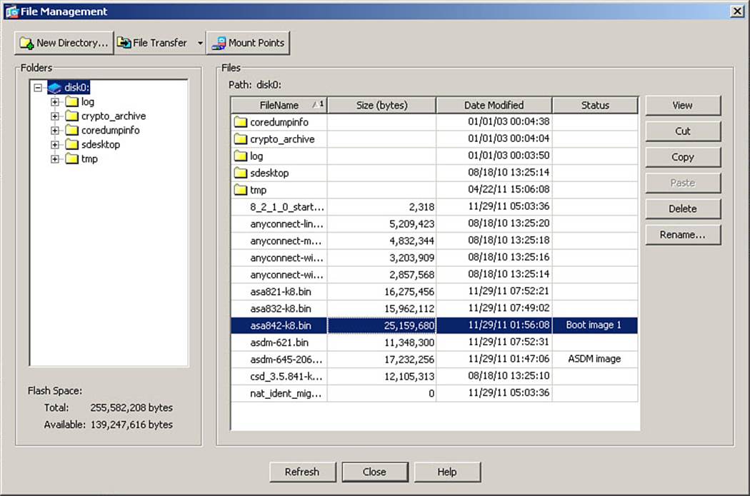
Figure 5-4. ASDM File Management Window
Note
File management using ASDM offers unique capabilities not accessible from the CLI: the capability to move files directly to or from the host on which ASDM is running, without a server protocol such as FTP or HTTP running on that host, or download updated images directly fromCisco.com.
Figure 5-4 shows the File Management window of a typical ASA. From this window, you can view, copy, move, delete, or rename files in flash memory, transfer files to the host running ASDM or remote servers using a variety of protocols, and manage files on remote mount points (remote storage devices). The window is split into two panes:
• Folders: This pane (on the left) allows quick navigation through available folders.
• Files: By default, this pane displays the contents of built-in flash memory (disk0:).
The buttons on the right side of the File Management window give immediate access to various file management functions: View (which opens a selected file in a browser window), Cut, Copy, Paste, Delete, and Rename.
Additionally, across the top of the File Management window are three buttons:
• New Directory: Creates a new directory on the file system
• File Transfer: Opens the File Transfer window, from which you can copy files to or from the computer running ASDM using the HTTPS connection of ASDM, or copy a file to or from a remote HTTP, HTTPS, FTP, or TFTP server
• Mount Points: Opens the Manage Mount Points window, enabling you to configure remote storage for file systems using a Common Internet File System (CIFS) or FTP connection
File System Management Using the CLI

The ASA CLI has equivalent file management functions. Although the sections that follow present some samples, full details on all possible parameters will not be covered in this book. Full information on the meaning and use of all available parameters is available in the Cisco ASA 5500 Series Command Reference, 8.4 and 8.5, which is available at www.cisco.com/en/US/docs/security/asa/asa84/command/reference/cmdref.html.
dir
The dir command, used without parameters, displays the contents of the current directory. You can specify other locations by adding appropriate parameters to the dir command. The syntax for the dir command is as follows:
dir [/all] [all-filesystems] [/recursive] [disk0: | disk1: | flash: | system:] [path]
Note
On a Cisco ASA, the keyword flash: aliases to disk0: (internal flash).
more
The more command displays the contents of a file. The syntax for the more command is as follows:
more [/ascii | /binary | /ebcdic] [disk0: | disk1: | flash: | ftp: | http: |
https: | smb: | system: | tftp:]filename
copy
The copy command is used to copy a file from one location to another. It can also be used to copy a file to your startup or running configuration. The syntax for the copy command is as follows:
copy [/noconfirm] [/pcap] {url | running-config | startup-config} {running-config
| startup-config | url}
Note
A server parameter within a URL can be expressed as an IP address or a name to be resolved by DNS or local name-to-address mappings.
delete
The delete command allows you to delete a file from the local flash file system only. The syntax for the delete command is as follows:
delete [/noconfirm] [/recursive] {disk0: | disk1: | flash:}filename
rename
The rename command allows you to rename a file on the local flash file system only. The syntax for the rename command is as follows:
rename [/noconfirm] {disk0: | disk1: | flash:}source-path {disk0: | disk1: |
flash:}destination-path
Example 5-4 demonstrates this command in action.
Example 5-4. Renaming a File
FIREWALL# rename disk0:/saved111010.cfg disk0:/test.cfg
Source filename [saved111010.cfg]? <press Enter>
Destination filename [test.cfg]? <press Enter>
FIREWALL#
mkdir
The mkdir command is used to create a new directory (make directory) in the file system. You are asked to confirm the creation, unless you specify the noconfirm parameter. If a directory with the specified name already exists, an error is generated and no new directory is created. The syntax for the mkdir command is as follows:
mkdir [/noconfirm] [disk0: | disk1: | flash:]path
In Example 5-5, an attempt is made to create a new directory named newdir, but this directory already exists.
Example 5-5. Attempting to Create a Duplicate Directory Name
FIREWALL# mkdir newdir
Create directory filename [newdir]?
%Error Creating dir disk0:/newdir (File exists)
FIREWALL#
rmdir
The rmdir command is used to delete a directory in the file system. You are asked to confirm the deletion, unless you specify the noconfirm parameter. The syntax for the rmdir command is as follows:
rmdir [/noconfirm] [disk0: | disk1: | flash:]path
Example 5-6 demonstrates this command in action.
Example 5-6. Removing a Directory from the Local File System
FIREWALL# rmdir newdir
Remove directory filename [newdir]?
Delete disk0:/newdir? [confirm]
FIREWALL#
cd
Use the cd command to change the current working directory to a specified location. If you do not specify a location, the working directory is changed to the root directory. The syntax for the cd command is as follows:
cd [disk0: | disk1: | flash:] [path]
pwd
Use the pwd command to display the current working directory (pwd stands for Print Working Directory).
In Example 5-7, an administrator changes the working directory to the “logs” directory. Note that the system prompt does not indicate the working directory location. Thus, the administrator uses the pwd command to confirm the current working directory. The example closes with a demonstration that using the cd command without parameters returns to the root directory.
Example 5-7. Changing Directory and Confirming Location
FIREWALL# cd logs
FIREWALL# pwd
disk0:/logs/
FIREWALL# cd
FIREWALL# pwd
disk0:/
FIREWALL#
fsck
If you suspect corruption in the local flash file system, you can use the fsck (file system check) command to check for it. If any is found, the ASA creates files with the name FSCKxxxx.REN, where xxxx is a sequential number starting with 0000. The ASA also performs a file system check every time it boots, so .REN files may appear in flash memory, even if you never use this command. These files sometimes contain a fraction of a file or even an entire file that was recovered by FSCK. In rare cases, you might need to inspect these files to recover data. Generally, these files are not needed and can be deleted. The syntax for the fsck command is as follows:
fsck [/noconfirm] {disk0: | disk1: | flash:}
Example 5-8 demonstrates this command in action.
Example 5-8. Performing a File System Check and Deleting .REN Files
FIREWALL# fsck disk0:
FIREWALL# delete FSCK*.REN
Delete filename [FSCK*.REN]? <press Enter>
Delete disk0:/FSCK0000.REN? [confirm] <press Enter>
Delete disk0:/FSCK0001.REN? [confirm] <press Enter>
FIREWALL#
Tip
The regular use of fsck to find and clear file system corruption is a good practice. Note that the ASA performs an fsck as part of its boot routine.
format or erase
You can completely erase all files in the local file system (including all hidden content such as startup-config, RSA private keys, and so on) using the format or erase command. The difference between these commands is that format rewrites the file allocation table, whereas erase overwrites all memory with the 0xFF pattern first. Therefore, using a raw disk read tool could see information deleted by format but not by erase. The syntax for the format and erase commands is as follows:
{format | erase} [disk0: | disk1: | flash:]
Caution
These commands should be used only in extraordinary circumstances because all data on the selected partition, including hidden system files, will be lost. Note also that use of either of these commands on disk0: (flash:) resets your device activation key to all zeros and removes licensing of all features beyond the standard feature set until a valid activation key is re-entered. This is because the activation key is stored in a hidden system file. Therefore, if you intend to use either of these commands, you should first execute the show version command and write down the displayed activation key. To delete only visible files (excluding hidden system files), use the delete /recursive command instead.
Managing Software and Feature Activation
Prior to software version 7.0, Cisco PIX Firewall allowed an administrator to place only three commonly used files on an ASA:
• One operating system binary
• One PDM file (the predecessor of ASDM)
• A startup-config file
Use of the dir command displayed cryptic information that didn’t facilitate the identification of individual files. No directories could be created. In short, it was not a truly functional file system.
As of version 7.0, there is much more flexibility for managing the file system, including the ability to place multiple versions of operating system binaries and ASDM images, as well as multiple configuration files, in an organized file system in flash, limited only by how much flash memory is installed on your particular ASA. Commands have been added to specify which version of each of these files you want the firewall to use from one boot to another. The complication that comes along with this flexibility is the need to maintain proper organization and ensure that the version of ASDM you intend to use is compatible with the operating system binary that you intend to use.
Managing Cisco ASA Software and ASDM Images
To upgrade ASA software or an ASDM image, you must first download the appropriate files from Cisco.com. ASDM includes a wizard that enables you to download these files directly to the ASA itself. It is vital to always ensure that the ASDM file you upgrade to is compatible with the operating system binary you upgrade to. Information on which ASDM versions are compatible with which system binaries is available on Cisco.com. You also need to ensure that the ASDM version you want to use is compatible with your local desktop.
Additionally, you should always read the relevant release notes before implementing any new version of operating system or ASDM (to ensure hardware and software compatibility) and familiarize yourself with any factors that may influence operation of the proposed versions in your particular networking environment.
To use ASDM to specify which system image binary, ASDM image, and, optionally, nonstandard startup configuration file to load upon the next reboot, navigate to Configuration > Device Management > System Image/Configuration > Boot Image/Configuration. From this screen, you can add an image to the list of available choices and set the order in which these files will be selected upon next boot. The ASA will boot with the first image listed, unless it is either unavailable or determined to be corrupted upon next boot. On this same screen, you can specify a compatible version of ASDM to load. Figure 5-5 shows a new image, asa823-k8.bin, being added to the list of choices. The Browse Flash dialog box is accessed by clicking Add and then clicking Browse Flash in the Add Boot Image dialog box.
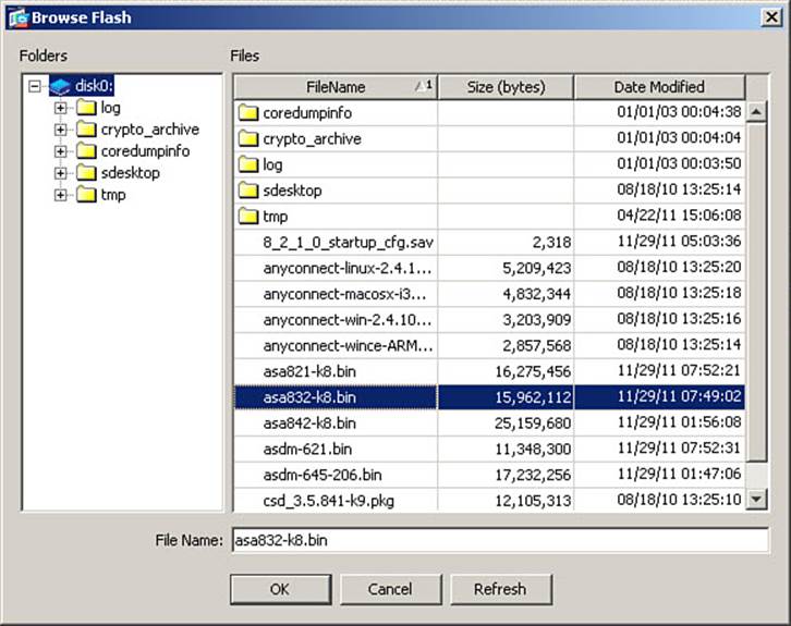
Figure 5-5. Adding a New Boot Image to the Boot Order List
Note
Whereas a change of operating system binary requires a reboot of the ASA, a change of ASDM image will be effective upon the next login to the ASA using ASDM.
Figure 5-6 shows the ASA boot order list after adding two additional image choices. You can adjust the order in which they will be searched by selecting an image name and clicking Move Up or Move Down to change the order.
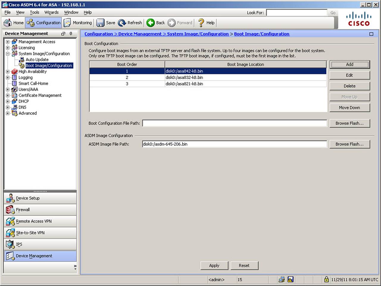
Figure 5-6. ASDM Boot Configuration Pane with Three Binary Choices in the Boot Order List
The CLI commands generated by the changes made are as follows:
boot system disk0:/asa832-k8.bin
boot system disk0:/asa821-k8.bin
If you are configuring the ASA from the CLI, you can enter these commands directly in global configuration mode. Note that because you are adding additional system images as fallback choices, these new commands appear below any existing boot system command in the ASA configuration.
Upgrading Files from a Local PC or Directly from Cisco.com
During normal operation, you can copy files to and from the flash file system and a TFTP, FTP, SMB, HTTP, or HTTPS server. As mentioned previously, if using ASDM, you can also transfer files directly to and from the host running ASDM or directly from Cisco.com. To do so, navigate toTools > Upgrade Software from Local Computer. In the Upgrade Software dialog box, choose whether the upgrade will come from the local computer or from Cisco.com. Select the type of file you want to upload from the Image to Upload list, which includes the following choices:
• APCF file
• ASA image file
• ASDM image file
• Client Secure Desktop (CSD) file
• Cisco AnyConnect VPN Client file
Note
The APCF, CSD, and AnyConnect files are related to functions covered in the VPN course, and therefore are not covered in this book.
If you are upgrading from the local computer, enter a path to the source file and then enter the path to where in flash memory you want to copy the file. To execute the update, click Upload Image. Figure 5-7 shows an ASDM image selected for copying from the local computer.
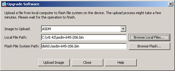
Figure 5-7. Image Update from Local Computer
As mentioned, you can also choose to upgrade directly from Cisco.com. To do so, navigate to Tools > Check for ASA/ASDM Updates, as shown in Figure 5-8.
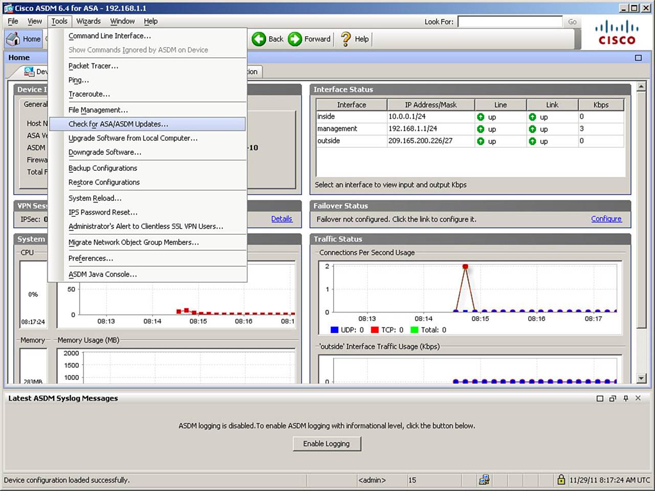
Figure 5-8. Choosing to Check for Software Updates Directly on Cisco.com
Note
To demonstrate this function, the ASA was temporarily downgraded to software version 8.3.2, and the 8.4.2 system binary was deleted from flash memory.
You are required to provide a valid Cisco.com username and password. Once you do, the Upgrade Software from Cisco.com Wizard opens. Complete the wizard to upgrade your ASA directly from Cisco.com. Figure 5-9 shows the wizard in action after selecting to upgrade the ASA to software version 8.4.2.
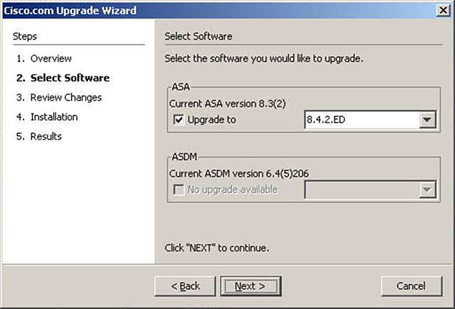
Figure 5-9. Cisco.com Upgrade Wizard
After upgrading images from either location, verify the correct boot order, as previously discussed, and reload the ASA. If using the Upgrade Wizard, you will be asked if you want to make the newly downloaded file the active system image, and reload the ASA. If you choose to do this, the wizard removes all existing boot system commands from the configuration and replaces them with a new list in the proper order, saves the changes to startup-config, and reloads the appliance.
Considerations When Upgrading from OS Version 8.2 to 8.3 or Higher
When upgrading an ASA to OS version 8.3 or higher for the first time, some items merit special attention.
Almost all ASA models have higher memory requirements for running these higher OS versions. Additionally, Cisco upgrading to versions 8.3 or higher only from version 8.2. It is important to consult the release notes for the version you intend to use to ensure your ASA meets the minimum memory requirements, and to ensure that your ASA is currently running software version 8.2 prior to performing a first upgrade to version 8.3 or higher.
Caution
It is possible that you could upgrade an ASA that contained less than the “required” amount of memory and it would function; however, any ASA containing less than the stated required minimum RAM is not supported by Cisco.
If you are upgrading an ASA from software version 8.2 to 8.3 or higher, and the ASA already has a configuration in place, the upgrade automatically updates the configuration to use the new NAT structure for versions 8.3 and higher. The version 8.2 configuration file and logs related to the migration process are saved as files in flash memory (as <version>_startup_cfg.sav and upgrade_startup_errors_<timestamp>.log, respectively).
If you are upgrading an ASA with a configuration, you should probably remove the nat-control command (covered in Chapter 7, in the sections, “Enforcing NAT” and “Configuring NAT Control”), if it is present in your configuration. Software versions 8.3 and higher do not support this command. If this command is present when the upgrade process migrates the configuration file, the ASA creates a NAT and ACL configuration that replicates the requirement that NAT take place in order for traffic to flow through the ASA between certain interfaces, which might add unnecessary complexity to your configuration.
The updating of the ASA to using the NAT structure required for versions 8.3 and higher also necessitates changes to any access lists, AAA rules, class maps, and so on that formerly made use of “mapped” IP addresses in versions prior to version 8.3. These features are all discussed elsewhere in this book. At this time, it is only important to know that these things will happen. You will see messages to this effect displayed on the ASA console the first time the ASA boots after being upgraded.
License Management
The ASA activates licensed features based on the currently installed activation key, which is a hexadecimal string that identifies the feature set available on this particular ASA. Note that activation keys are not transferrable between ASAs. The activation key is bound to the flash BIOS serial number (shown in the show version command output, which is sometimes not the same as the chassis serial number that is engraved on the outside of the chassis). Some features are permanent, purchased features, while others can be temporary, test, and demonstration features.
You can view and update the ASA activation key and licensed feature set from ASDM or the CLI. In ASDM, navigate to Configuration > Device Management > Licensing > Activation Key. As shown in Figure 5-10, the Activation Key window has three areas:
• Permanent Activation Key: This area displays the ASA serial number and the Permanent Activation Key.
• New Activation Key: Enter a new activation key in this area to update the activation key running on the ASA.
• Effective Running Licenses: This area lists licensed features, the license value (whether the feature is active, or a quantity for items such as VLANs, security contexts, SSL VPN peers allowed, and so on), and a license duration, which is listed as “perpetual” for permanently licensed features.
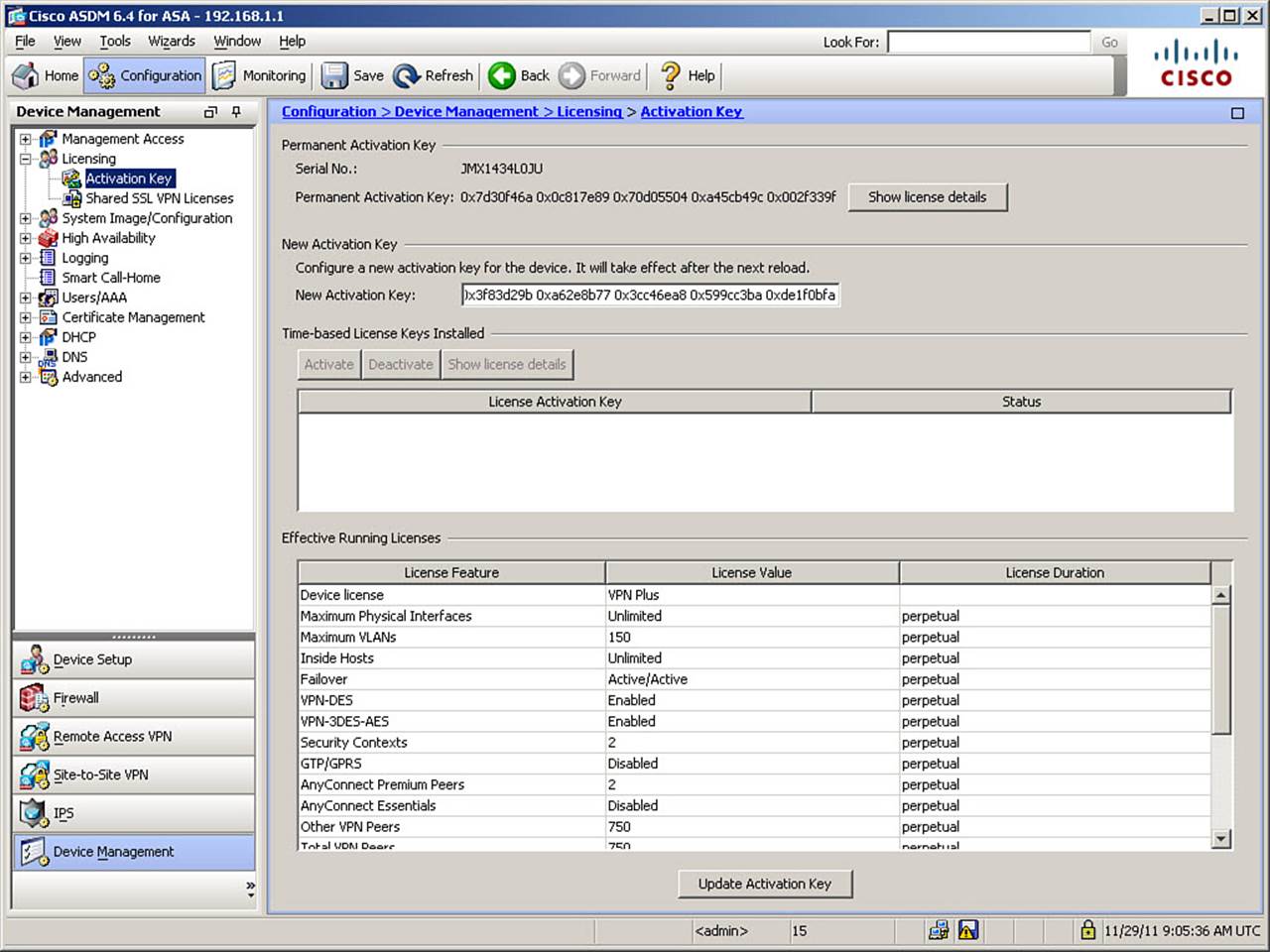
Figure 5-10. Changing Activation Key with ASDM
Note
Older versions of ASA software show blank License Duration for permanently licensed features.
Figure 5-10 shows an example of using ASDM to enter a new activation key on an ASA. Note that when typing an activation key, leading 0x is optional, as all values are assumed to be hexadecimal. Click Update Activation Key, and the new activation key is applied to the system image on the ASA. Note that the activation key is not part of the ASA configuration file but is stored in a hidden system file within flash memory.
The new activation key should not take effect until the next reboot of the ASA. You can verify this by using the CLI command show activation-key. The final line of output will state that the flash activation key is not the same as the running key. You can also use the command show activation-key detail to display both permanent and temporary activation keys with their enabled features, including all previously installed temporary keys and their expiration dates.
Upgrading the Image and Activation Key at the Same Time
Because an image upgrade will, and an activation key change should, require an ASA reboot, it is generally advisable, if changing both, to reboot as part of the same maintenance procedure.
Because the new key might be necessary to activate features not present in the current system image, the preferred method of doing this requires two reboots.
When you upgrade the system image file, the existing activation key is extracted from the original image and stored in a file in the ASA to be applied to the upgraded image. There is no need to change activation keys when updating system images, unless you are activating a new feature set.
To upgrade both the system image and activation key at the same time, first install the new image, and then reboot the system. Once rebooted, update the activation key, and reboot again.
If you are downgrading an image, you need to reboot only once, after installing the new image. The old key is both verified and changed with the current image.
Cisco ASA Software and License Verification
To verify the current system image software version and ASDM version used by the ASA, navigate to the Home view in ASDM, as shown in Figure 5-11.
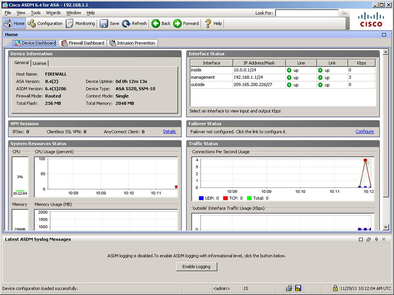
Figure 5-11. Verifying Image Information in the ASDM Home View
As shown in Figure 5-11, the ASA system image and ASDM image versions, device type, and firewall and context modes are all listed. To view key licensed features, click the License tab, as shown in Figure 5-12.
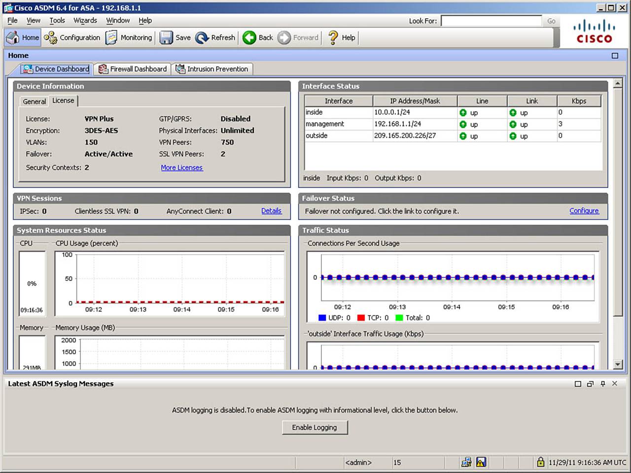
Figure 5-12. Verifying License Information in ASDM
As shown in Figure 5-12, key license information is displayed on the License tab. Clicking the More Licenses hyperlink opens the Activation Key window shown previously, in Figure 5-10.
The same information can be verified using the CLI show version command, as shown in Example 5-9. Key information discussed in this section is highlighted for easy reference.
Example 5-9. Verifying Device Image and License Information
FIREWALL# show version
Cisco Adaptive Security Appliance Software Version 8.4(2)
Device Manager Version 6.4(5)206
Compiled on Fri 26-Aug-11 14:59 by builders
System image file is "disk0:/asa842-k8.bin"
Config file at boot was "startup-config"
FIREWALL up 41 mins 32 secs
Hardware: ASA5520, 2048 MB RAM, CPU Pentium 4 Celeron 2000 MHz
Internal ATA Compact Flash, 256MB
BIOS Flash M50FW016 @ 0xfff00000, 2048KB
Encryption hardware device : Cisco ASA-55x0 on-board accelerator (revision 0x0)
Boot microcode : CN1000-MC-BOOT-2.00
SSL/IKE microcode : CNLite-MC-SSLm-PLUS-2.03
IPSec microcode : CNlite-MC-IPSECm-MAIN-2.06
Number of accelerators: 1
0: Ext: GigabitEthernet0/0 : address is c84c.75be.15a8, irq 9
1: Ext: GigabitEthernet0/1 : address is c84c.75be.15a9, irq 9
2: Ext: GigabitEthernet0/2 : address is c84c.75be.15aa, irq 9
3: Ext: GigabitEthernet0/3 : address is c84c.75be.15ab, irq 9
4: Ext: Management0/0 : address is c84c.75be.15ac, irq 11
5: Int: Internal-Data0/0 : address is 0000.0001.0002, irq 11
6: Int: Internal-Control0/0 : address is 0000.0001.0001, irq 5
Licensed features for this platform:
Maximum Physical Interfaces : Unlimited perpetual
Maximum VLANs : 150 perpetual
Inside Hosts : Unlimited perpetual
Failover : Active/Active perpetual
VPN-DES : Enabled perpetual
VPN-3DES-AES : Enabled perpetual
Security Contexts : 2 perpetual
GTP/GPRS : Disabled perpetual
AnyConnect Premium Peers : 2 perpetual
AnyConnect Essentials : Disabled perpetual
Other VPN Peers : 750 perpetual
Total VPN Peers : 750 perpetual
Shared License : Disabled perpetual
AnyConnect for Mobile : Disabled perpetual
AnyConnect for Cisco VPN Phone : Disabled perpetual
Advanced Endpoint Assessment : Disabled perpetual
UC Phone Proxy Sessions : 2 perpetual
Total UC Proxy Sessions : 2 perpetual
Botnet Traffic Filter : Disabled perpetual
Intercompany Media Engine : Disabled perpetual
This platform has an ASA 5520 VPN Plus license.
Serial Number: JMX1434L0JU
Running Permanent Activation Key: 0x7d30f46a 0x0c817e89 0x70d05504 0xa45cb49c
0x002f339f
Configuration register is 0x1
Configuration last modified by enable_15 at 09:02:08.259 UTC Tue Nov 29 2011
Configuring Management Access
There are several access methods available for managing a Cisco ASA. The management interface can be accessed locally; using the console port; or remotely using Telnet, SSH, or HTTPS if the ASA is configured to accept these remote connection types. Additionally, the ASA supports the use of SNMP, but SNMP for management is limited to read-only access to the ASA, so it is used only for monitoring. The use of SNMP for monitoring is covered later in the chapter in the section, “Configuring Monitoring Using SNMP.”
If you are using remote access for management, it is imperative that you securely configure such access, to ensure the integrity of the ASA, particularly if you are using in-band management access (the management path uses an untrusted network, which includes any network bearing nonmanagement traffic, such as user or application traffic) instead of out-of-band (OOB) access (using a dedicated management network).
The sections that follow describe how to configure management access to the ASA, how to configure remote management access, how to configure AAA features, and how to troubleshoot management access.
Securing the local console port beyond the use of an enable password requires the use of AAA, as covered in the section, “Controlling Management Access with AAA.”
Overview of Basic Procedures
When designing and implementing local or remote management access to the ASA, you need to perform some or all of the following main configuration tasks:
• Configure remote management channels to the ASA, choosing optimal protocols and using proper access control to limit the possible sources of remote management connections. Give preference to secure protocols such as SSH and SSL, even if using OOB networks for management access.
• Configure appropriately strong authentication for remote management access to gain assurance of remote administrator identity before allowing access to the ASA management interface.
• Configure authorization for the use of management features and commands, to differentiate various management roles and provide a policy where each administrator has the minimal required rights to perform their assigned job tasks (least-privilege Role-Based Access Control [RBAC] policy).
• Configure accounting for management access, to establish an audit trail for the purposes of intrusion detection, monitoring of management practices, and documentation required for compliance with various directives.
Note that these configuration tasks might not all be necessary in every environment, depending on the local organizational requirements, security policy, and management practices and capabilities.
Before deploying these management functions, you should consider several factors, including the following:
• Existing administrator computing platforms (operating systems and applications) and the software available to administrators to perform management tasks: These need to be verified for their compatibility with the ASA management functions.
• Existing authentication methods and infrastructures present in the network, such as existing AAA servers, and their supported protocols: This information is necessary to properly integrate the ASA into the existing infrastructure. Sometimes it might not be feasible to integrate the ASA into an existing infrastructure or to create a new centralized AAA infrastructure. In such a case, you might need to deploy the local AAA subsystem of the ASA and use a local user authentication and authorization database. Note that there is no local accounting database for administrative actions.
• Existing security policies related to infrastructure management processes: These policies might dictate the use of particular security controls for management access, particular management protocols, or a particular workflow process when managing devices.
• The trustworthiness and type of management paths between administrators and the ASA: This is necessary to determine the need for strongly authenticated, cryptographically protected management protocols that can operate over untrusted networks, and/or to choose between in-band or out-of-band management paths.
When deploying remote management access to the ASA, consider the following general deployment guidelines:
• Analyze all paths between administrators and the ASA end to end. If any part of such paths is routed across untrusted networks, use only encrypted management protocols coupled with strong authentication.
• Give preference to centralized AAA infrastructures rather than local AAA on the ASA. Centralized systems are more manageable and scalable and allow for centralized auditing.
• Group administrators into role-based groups and grant each group only the minimal privileges required for that particular administrative role (least-required privileges model).
• Use an administrative model in which no one person is allowed to make changes to security-critical settings. For example, you could let several people each know only a portion of a required passphrase, or you could implement a management system requiring review cycles for change control, where a configuration change created by one person needs to be approved by another (known as “dual control”).
Configuring Remote Management Access
The Cisco ASA provides three remote access management protocols to access management functions: Telnet, Secure Shell (SSH), and HTTP over SSL/TLS (HTTPS).
Unlike some networking platforms that allow management access by default, the Cisco ASA must be configured to accept management access from specific source IP ranges, on specific interfaces, on a per-management-protocol basis, before any remote management access will succeed.
Telnet is a clear-text (and thus inherently unsecured) access protocol that authenticates access to the ASA based on the IP address of the session source (hence its strength is bounded by the resistance of the intermediate network path to IP spoofing) and authenticates administrators based on passwords or one-time passwords (OTP). If AAA is in use, usernames can also be required (covered later). The Telnet protocol should never be used over untrusted networks, and is generally considered obsolete for security device management. You should instead use SSH wherever possible.
The SSH protocol is a strongly encrypted and strongly authenticated protocol, allowing CLI terminal access to the ASA. The SSH protocol authenticates the ASA to the administrator using public-key-based authentication, and authenticates administrators to the ASA based on a combination of username and password or OTP. In the absence of AAA, a default username of “pix” is used. The SSH protocol can be used over untrusted networks, provided appropriate care is taken when managing the ASA’s public key (not accepting it over an untrusted network without using some OOB verification mechanism, or having a preprovisioned authentic copy already stored on the client system).
The HTTPS protocol is also a strongly encrypted and strongly authenticated protocol, allowing access to the ASA using ASDM. The HTTPS protocol authenticates the ASA to the administrator using public-key-based authentication in the form of X.509 certificates (a self-signed certificate is used by default), and authenticates administrators to the ASA using a password, OTP, or client X.509 certificate. The HTTPS protocol can be used over untrusted networks, provided appropriate care is taken when managing the ASA’s public key, similar to that previously detailed for SSH.
Configuring an Out-of-Band Management Interface
The first, optional task when configuring remote management access to the Cisco ASA is to dedicate one of its network interfaces as a management-only interface. You would typically use a dedicated management interface only in environments using a dedicated, out-of-band management network to access management interfaces of network devices and systems.
An ASA interface configured as a management-only interface can accept and respond to traffic where the ASA itself is the destination (PING, management session, and so on), but cannot pass any transit traffic through the ASA to or from another interface. Despite this restriction, you still need to specify in the ASA configuration exactly which systems can access the ASA using remote management protocols over the dedicated management network. Additionally, you might need to configure routes to remote management systems through the dedicated management interface.
If you are using OOB management, recommended practice dictates that you use the Management0/0 physical interface of the ASA for this function, as it is the lowest-bandwidth interface of the ASA. Additionally, as a precaution, consider applying a high security level to this interface and placing a deny-all transit access list on the interface (interface access lists are covered in Chapter 8, “Controlling Access Through the ASA”), in case the management-only setting is ever accidentally removed.
Note
Although the Cisco ASA 5500 Series appliances have a physical interface named Management0/0, this interface does not have to be used as an OOB management interface. Additionally, any other interface could be designated as a management-only interface.
To configure any ASA routed interface as a dedicated management interface, navigate to Configuration > Device Setup > Interfaces. Select an interface from the interfaces pane, and then click Edit to open the Edit Interface dialog box, shown in Figure 5-13.
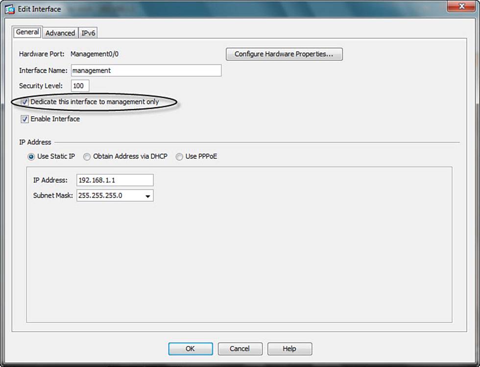
Figure 5-13. Configuring an OOB Management Interface
Figure 5-13 shows the Edit Interface dialog box for the Management0/0 interface. To set the selected interface to be an OOB management interface, check the Dedicate This Interface for Management Only check box, click OK, and then click Apply.
The CLI commands generated by the changes made are as follows:
interface Management0/0
management-only
If you are configuring the ASA from the CLI, you can enter these commands directly in global configuration mode.
Note
The Management0/0 physical interface is assigned a security level of 0 by default, so the details shown in Figure 5-13 are based on alterations previously made in compliance with the best practices mentioned earlier, of assigning a high security level to this interface, in case the management-only parameter was ever removed accidentally.
Configuring Remote Access Using Telnet
Although the use of Telnet is generally not recommended, you might prefer it on occasion. For example, you might require Telnet if you are using a client that does not support SSH; if you are managing a device on a secure OOB network, where there is no possibility of rogue sniffers being present; or if you are managing a device through a VPN tunnel that already provides encryption for the management session. In such a case, you can enable the Telnet server of a Cisco ASA by specifying the IP addresses that can connect to the ASA using Telnet, along with the interface that such source addresses are allowed to use Telnet to reach.
By configuring Telnet access, you can allow a maximum of five concurrent Telnet connections to an ASA (or per context, if using multicontext mode, with a maximum of 100 connections divided among all contexts).
To configure Telnet access to the ASA, navigate to Configuration > Device Management > Management Access > ASDM/HTTPS/Telnet/SSH. In the ASDM/HTTPS/Telnet/SSH window, click Add to add an access rule. The Add Device Access Configuration dialog box opens, as shown in Figure 5-14.
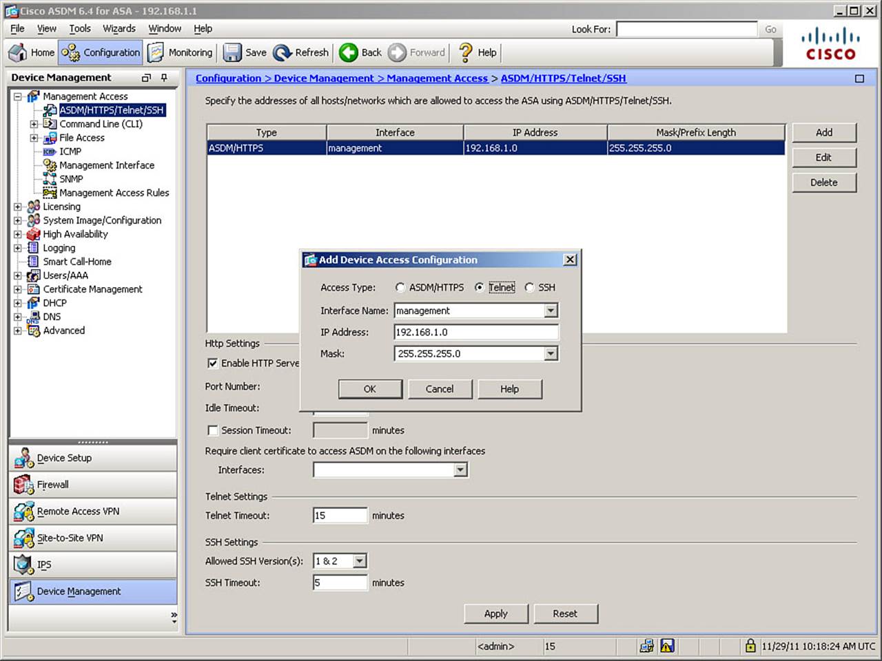
Figure 5-14. Configuring a Telnet Access Rule
As shown in Figure 5-14, you can configure a Telnet access rule in the Add Device Access Configuration dialog box by selecting Telnet as the access type and then specifying the IP address and mask of the source of permitted access sessions, along with the incoming interface where the session will reach the ASA. Click OK to finish defining the rule. The example in Figure 5-14 allows incoming Telnet sessions from the 192.168.1.0/24 network to arrive on the management (Management0/0) interface. Because the management network is OOB in the example network, and thus secure from other network segments, it is the only interface for which allowing an unsecured protocol might be acceptable.
To set the maximum time, in minutes, that a Telnet session can be idle before being logged out by the ASA, enter a value from 1 to 1440 in the Telnet Timeout field. By default, Telnet sessions are closed after being idle for 5 minutes. Figure 5-14 shows a setting of 15 minutes. Click Applyto apply the completed Telnet access rule to the configuration.
The CLI commands generated by the changes made are as follows:
telnet timeout 15
telnet 192.168.1.0 255.255.255.0 management
If you are configuring the ASA from the CLI, you can enter these commands directly in global configuration mode.
Tip
Although it is possible to configure a Telnet access rule on any interface of the ASA, Telnet traffic will be refused at the lowest security level (usually “outside”) interface, unless it arrived at the ASA under the protection of an IP Security (IPsec) tunnel. This works only with IPsec, not with an SSL VPN tunnel. It is generally preferred to enable Telnet sessions to the inside interface and designate this as the management interface for sessions coming through an encrypted tunnel, using the management-access inside command. Note that this method works over both IPsec and SSL VPN tunnels. For more information, refer to the Cisco ASA 5500 Series Command Reference, 8.4 and 8.5, which is located at www.cisco.com/en/US/docs/security/asa/asa84/command/reference/cmdref.html.
To view or clear Telnet sessions, you can use the following commands:
• who: Displays which IP addresses are currently accessing the ASA console via Telnet.
• kill session id: Terminates a designated Telnet session (the session id number is obtained with the who command). When you kill a Telnet session, any active commands terminate normally, and then the ASA drops the connection, without warning the user.
Configuring Remote Access Using SSH
The SSH protocol provides an option for secure remote management of the ASA. Like Telnet, the ASA allows up to five concurrent SSH connections per context, with up to 100 total SSH sessions across all security contexts, when in multicontext mode.
Before you can enable the SSH server on the ASA, you must provide the ASA with a public-private pair of RSA keys. You can create an RSA key pair (or replace an existing pair) by using the crypto key generate rsa command from CLI global configuration mode. The full syntax and options are as follows:
crypto key generate rsa [usage-keys | general-keys] [label key-pair-label]
[modulus size] [noconfirm]
• general-keys: Generates a single pair of general-purpose keys. This is the default key-pair type.
• label key-pair-label: Specifies the name to be associated with the key pair(s). This key pair must be uniquely labeled. If you attempt to create another key pair with the same label, the ASA displays a warning message. If no label is provided when the key is generated, the key pair is statically named <Default-RSA-Key>.
• modulus size: Specifies the modulus size of the key pair(s): 512, 768, 1024, or 2048. The default modulus size is 1024.
• noconfirm: Suppresses all interactive prompting.
• usage-keys: Generates two key pairs, one for signature use and one for encryption use. This implies that two certificates for the corresponding identity are required.
The default key-pair type is general-keys. SSH connections always use this key pair. The default modulus size is 1024. If replacing an existing pair, first use the crypto key zeroize rsa default command to delete the existing pair, as demonstrated in Example 5-10.
Example 5-10. Creating a Default RSA Key Pair
FIREWALL(config)# crypto key zeroize rsa default
FIREWALL(config)# !Use to delete an existing default RSA key pair
FIREWALL(config)# copy running-config startup-config
FIREWALL(config)# !Save the configuration with no default RSA key pair
FIREWALL(config)# crypto key generate rsa modulus 2048
INFO: The name for the keys will be: <Default-RSA-Key>
Keypair generation process begin. Please wait...
FIREWALL(config)# copy running-config startup-config
Once an RSA key pair exists for use, configuring SSH access is almost exactly the same as configuring Telnet access, with the exception that it is also possible to limit which SSH version can be used by clients to initiate management sessions. Whenever possible, you should use SSH version 2 only because it has stronger methods of key management and message integrity checking. Additionally, the idle time can be set from 1 to 60 minutes, whereas Telnet allows a range from 1 to 1440.
To configure SSH access to the ASA, navigate to Configuration > Device Management > Management Access > ASDM/HTTPS/Telnet/SSH and click Add, as shown in Figure 5-15.
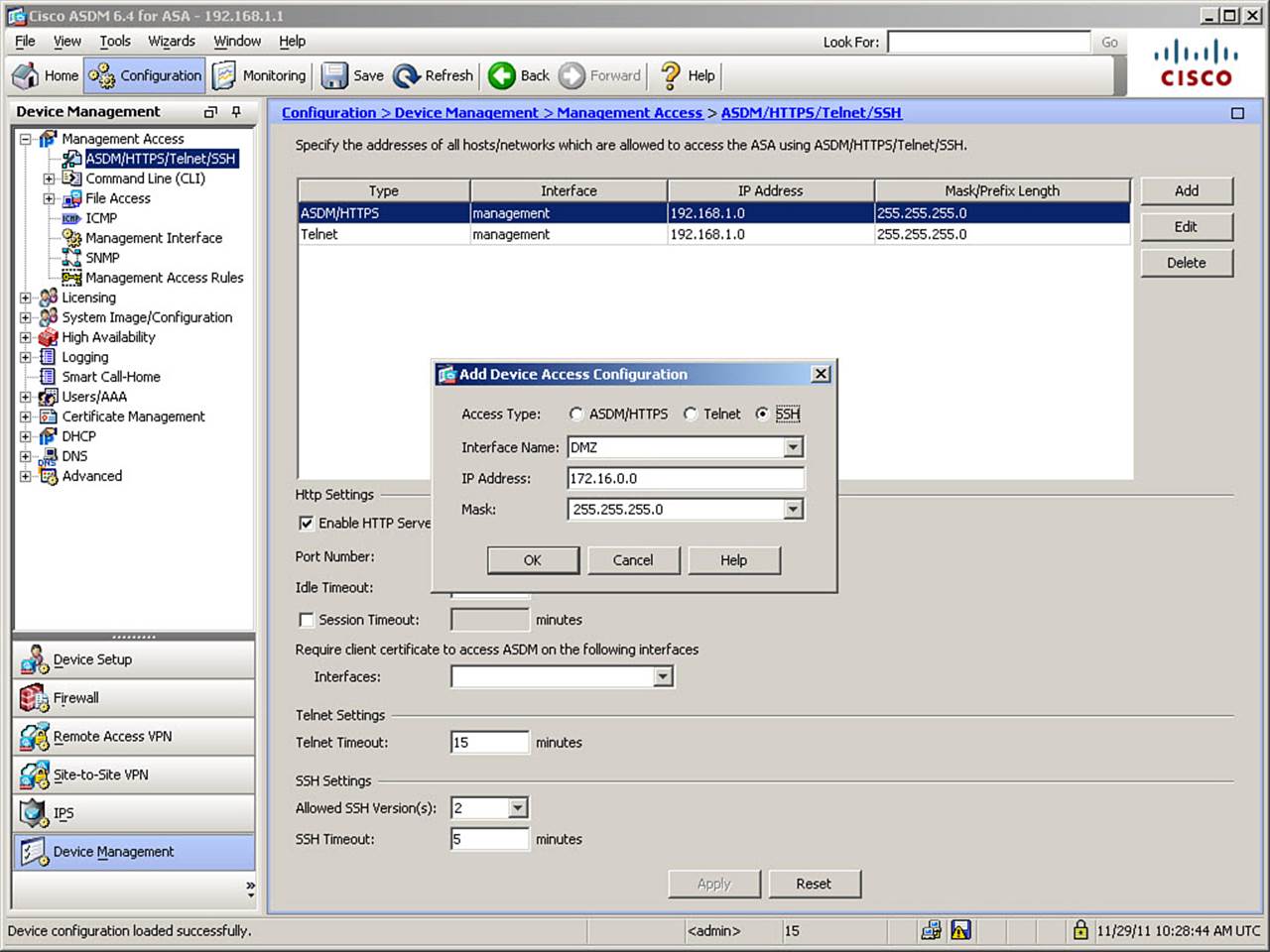
Figure 5-15. Configuring an SSH Access Rule
The example in Figure 5-15 allows incoming SSH sessions from the 172.16.0.0/24 network to arrive on the DMZ interface. Additionally, only SSH version 2 is permitted. The idle timeout is left at the default of 5 minutes.
The CLI commands generated by the changes made are as follows:
ssh version 2
ssh 172.16.0.0 255.255.255.0 DMZ
If you are configuring the ASA from the CLI, you can enter these commands directly in global configuration mode.
To view or clear SSH sessions, you can use the following commands:
• show ssh sessions: Displays which IP addresses are currently accessing the ASA console via SSH, as well as the SSH version used, the encryption algorithm used for the session, the session state, and the username that is logged in.
• ssh disconnect session id: Terminates a designated SSH session (the session id number is obtained with the show ssh sessions command), similarly to the kill command.
Configuring Remote Access Using HTTPS
HTTPS management access is used by ASDM. To configure HTTPS access to the ASA, the ASA must have an HTTPS X.509 server certificate. The ASA uses this certificate to authenticate itself to the client (browser or ASDM Launcher application). By default, the ASA will generate a self-signed server certificate each time it is rebooted, for this purpose. However, this changing certificate leads to a lot of browser security warnings because it cannot be verified. Therefore, you might want to generate a permanent self-signed certificate or, better yet, enroll the ASA in a Public Key Infrastructure (PKI) and obtain a server certificate in this manner. Generating a permanent self-signed certificate is simpler, and acceptable if accessing the ASA over a secure network, but enrolling the ASA in a PKI is more scalable, and thus the recommended solution.
Creating a Permanent Self-Signed Certificate
By creating a self-signed server certificate that is persistent across reboots, you can save the certificate on the administrator’s client computer and thus avoid further browser security warnings when administering the ASA using HTTPS.
To deploy a permanent self-signed certificate, you must first set the ASA hostname and domain name (covered earlier in the section, “Configuring Device Identity”) to insert a proper subject name in the server certificate. Additionally, you must generate an RSA key pair (you can use the default key pair, or generate a labeled key pair, for use with the server certificate, so that SSH and HTTPS access rely on different RSA keys).
To configure a permanent self-signed certificate using ASDM, navigate to Configuration > Device Management > Certificate Management > Identity Certificates and click Add. The Add Identity Certificate dialog box opens, as shown in Figure 5-16.
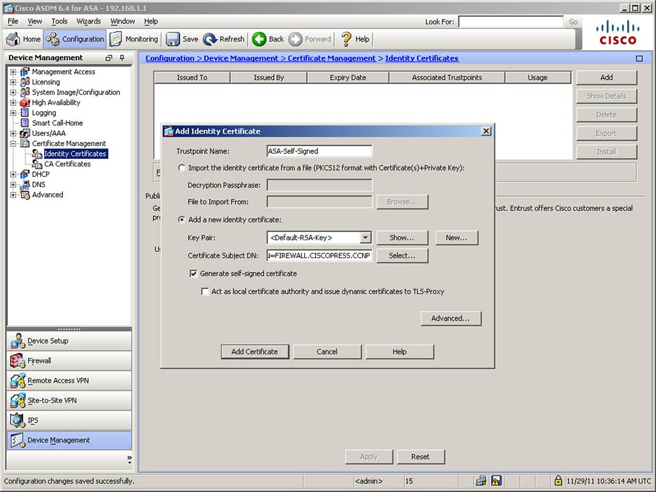
Figure 5-16. Creating a Permanent Self-Signed Certificate
In the Add Identity Certificate dialog box, a trustpoint name is defined (which is how this certificate can be referenced in configuring features that use certificates). The ASA auto-generates trustpoint names, although you can also define your own name. In Figure 5-16, the default name is replaced with a new name of ASA-Self-Signed to clearly identify this certificate as self-signed.
You can import an identity certificate from a file, but in Figure 5-16, the choice is made to add a new identity certificate. You can then either select a key pair or create one by clicking the New button. In Figure 5-16, the default RSA key pair is selected.
Certificates must be bound to a specific identity. In X.509 certificates, the identity is known as the Subject Name. The ASA prefills the Certificate Subject DN (Distinguished Name) field with the device hostname. Generally, you will want to enter the common name of the ASA in the form CN=hostname.domainname for an identity certificate. If you want to construct a more complex Subject DN, click the Select button and create the desired string in the Certificate Subject DN dialog box. Figure 5-16 shows the Subject DN of CN=FIREWALL.CISCOPRESS.CCNP.
Because the purpose is to create a self-signed certificate, check the Generate Self-Signed Certificate check box, as shown in Figure 5-16. Click the Add Certificate button to finish creating the certificate. Finally, click Apply to send the generated commands to the ASA.
The CLI commands generated by the changes made are as follows:
crypto ca trustpoint ASA-Self-Signed
id-usage ssl-ipsec
no fqdn
subject-name CN=FIREWALL.CISCOPRESS.CCNP
enrollment self
crypto ca enroll ASA-Self-Signed noconfirm
If you are configuring the ASA from the CLI, you can enter these commands directly in global configuration mode.
Obtaining an Identity Certificate by PKI Enrollment
Instead of using a self-signed certificate, you could enroll the ASA in a Public Key Infrastructure (PKI) and deploy the PKI-provisioned certificate to the ASA. This is the preferred and more scalable method. It is similar to the creation of a self-signed certificate, except that you have to forward your certificate enrollment request (containing identifying information and the ASA’s public RSA key) to a PKI enrollment server (a registration authority [RA] or a certificate authority [CA]).
Enrollment with a PKI can be done using one of two methods:
• Manually, wherein you copy and paste your certificate information into the RA or CA interface as instructed.
• Simple Certificate Enrollment Protocol (SCEP), wherein you define an Enrollment URL (provided to you by the CA) and any relevant password, and the remainder of the process happens automatically, essentially without further human intervention. Note that this depends on the configuration of the CA server.
To enroll with a PKI for a certificate using ASDM, navigate to Configuration > Device Management > Certificate Management > Identity Certificates and click Add. In the Add Identity Certificate dialog box (shown previously in Figure 5-16), accept the autogenerated trustpoint name, click the Add a New Identity Certificate radio button, choose an RSA key pair, and construct a Subject DN, as detailed previously for self-signed certificates. Leave the Generate Self-Signed Certificate check box unchecked. To enroll in a PKI, next click the Advanced button. The Advanced Options dialog box opens, as shown in Figure 5-17.
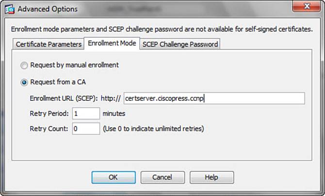
Figure 5-17. Enrolling in a PKI for an Identity Certificate
Click the Enrollment Mode tab, and click the Request from a CA radio button to specify the enrollment method. The Enrollment URL (SCEP) field is already prepended with “http://” and is completed in Figure 5-17 with certserver.ciscopress.ccnp. In this example, no SCEP challenge password is required, so you can simply click OK to finish defining advanced options. Finally, click Apply to send the generated commands to the ASA.
The CLI commands generated by the changes made are as follows:
crypto ca trustpoint ASDM_TrustPoint0
id-usage ssl-ipsec
no fqdn
subject-name CN=FIREWALL.CISCOPRESS.CCNP
enrollment url http://certserver.ciscopress.ccnp
crypto ca authenticate ASDM_TrustPoint0 nointeractive
crypto ca enroll ASDM_TrustPoint0 noconfirm
If you are configuring the ASA from the CLI, you can enter these commands directly in global configuration mode.
Deploying an Identity Certificate
After you have obtained an identity certificate for the ASA, you must next bind the self-signed or PKI-obtained identity certificate to the interface(s) on which you want the ASA to accept HTTPS management sessions. To do so, navigate to Configuration > Device Management > Advanced > SSL Settings.
In the SSL Settings window, go to the Certificates area (bottom) and select an interface on which you want the ASA to accept HTTPS management connections. Then, click Edit to open the Select SSL Certificate dialog box, shown in Figure 5-18.
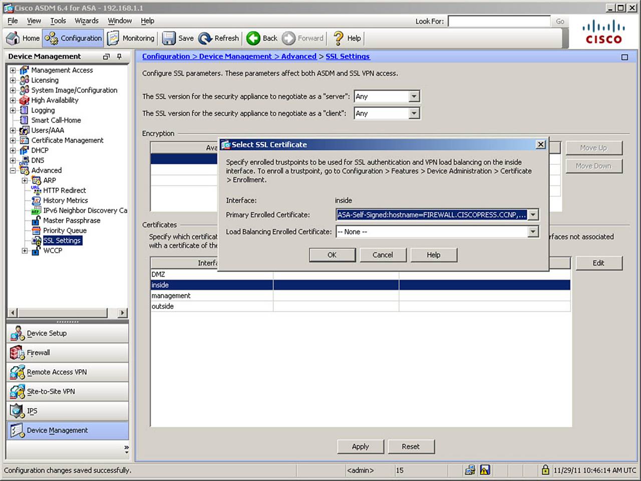
Figure 5-18. Binding an Identity Certificate to an ASA Interface
In the Primary Enrolled Certificate drop-down box, the self-signed or PKI-obtained certificate is selected. In Figure 5-18, the ASA-Self-Signed certificate is selected for use on the inside interface. Repeat these steps to activate the self-signed certificate on the management interface.
The CLI commands generated by the changes made are as follows:
ssl encryption rc4-sha1 aes128-sha1 aes256-sha1 3des-sha1
ssl trust-point ASA-Self-Signed inside
ssl trust-point ASA-Self-Signed management
If you are configuring the ASA from the CLI, you can enter these commands directly in global configuration mode.
Note
If you want a particular identity certificate associated with all interfaces to which a specific certificate is not bound, you can select it in the Fallback Certificate field at the bottom of the SSL Settings window. The fallback certificate is used on all interfaces not associated with a certificate of their own. Note also that this includes the outside interface, so strong authentication of users is exceptionally important.
After you have bound a server certificate to an ASA interface connected to a trusted network, browse to the ASA from the Administrator client and permanently install the ASA self-signed certificate in the browser. The specific steps differ depending on the browser used.
After you have created or obtained an identity certificate and bound it to an interface of the ASA, you need to configure the ASA to accept HTTPS administrative sessions, in the same manner as for Telnet or SSH.
To configure HTTPS access to the ASA, navigate to Configuration > Device Management > Management Access > ASDM/HTTPS/Telnet/SSH, and then click Add to open the Add Device Access Configuration dialog box, as shown in Figure 5-19.
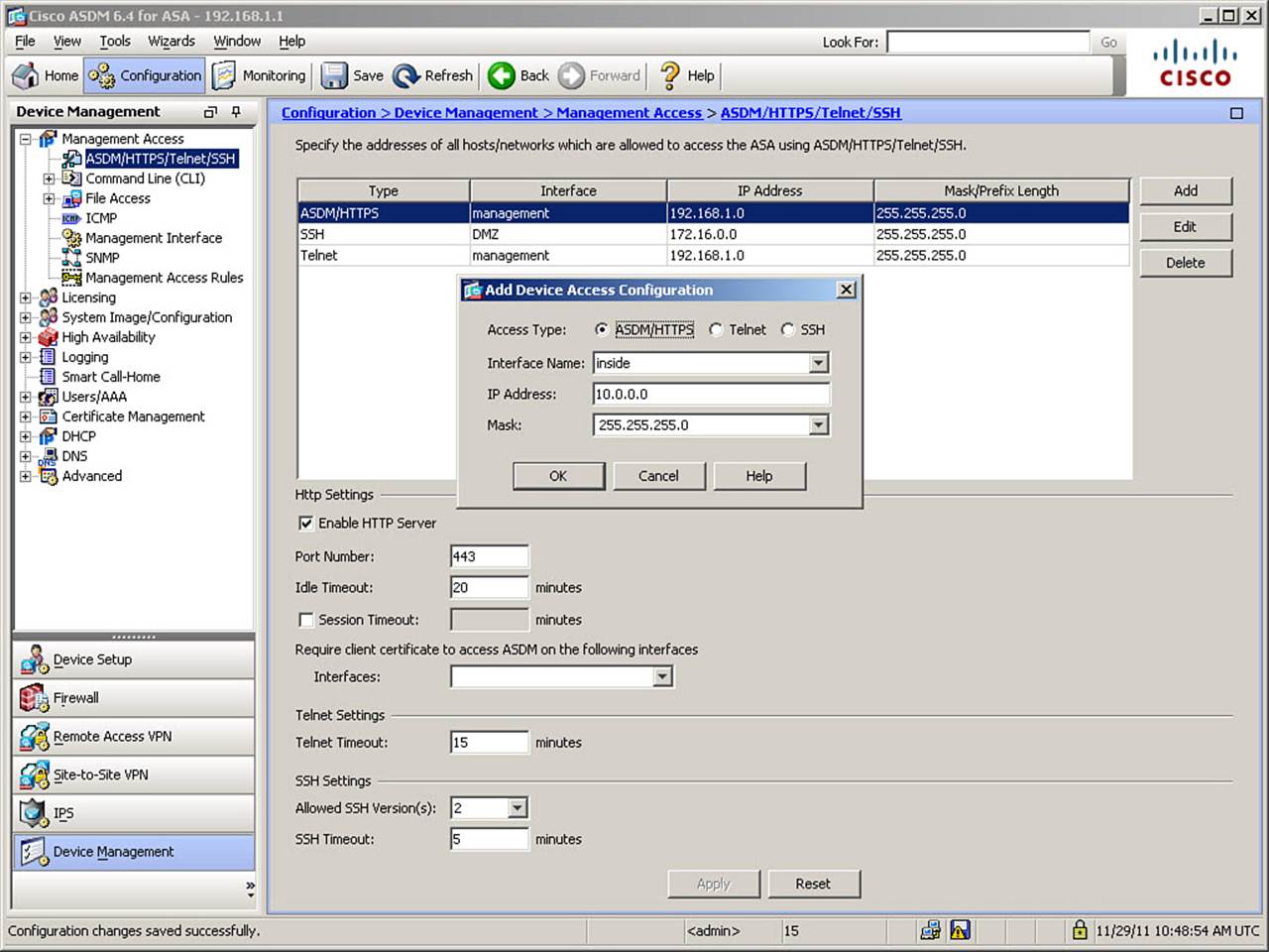
Figure 5-19. Configuring an HTTPS Access Rule
In Figure 5-19, HTTPS access is configured for the inside interface, with potential source IPs in the 10.0.0.0/24 network. Also, in the ASDM/HTTPS/Telnet/SSH window, ensure that the Enable HTTP Server check box is checked (it is by default). Additional options are available to change the TCP port on which the ASA listens for HTTPS connections, set an idle time for session closure, or set a session timeout value, which limits the maximum connection time even for sessions that are not idle. Repeat these steps to allow ASDM access from the network attached to the management interface.
The CLI command generated by the changes made is as follows:
http 10.0.0.0 255.255.255.0 inside
http 192.168.1.0 255.255.255.0 management
If you are configuring the ASA from the CLI, you can enter these commands directly in global configuration mode.
Configuring Management Access Banners
An ASA has the capability to display various configured banners both before and after login using various types of access to its management interface. These banners can contain whatever information is deemed appropriate in your environment, based on your local security policy. They are generally used to inform users of terms of use, warn of the consequences of unauthorized access, or display important maintenance-related information. Occasionally, they contain administrator contact information.
The banners supported by the ASA are as follows:
• Message-of-the-day (MOTD) banner: The first banner displayed when connecting to the console port, or remotely using Telnet or SSH. This banner is displayed before the CLI login banner and is generally where messages such as contact information are displayed.
• Login banner: Displayed before the CLI login prompt and is generally used to warn users against unauthorized access attempts.
• Exec banner: Displayed after CLI login and is generally used for messages such as maintenance-related information or reminders for all administrators.
• ASDM banner: Displayed after ASDM login. Because ASDM is an alternate management interface, and this banner is the only one seen by users logging in through ASDM, it should include all the same information as the login banner, at a minimum. It might be used to include all the information in all the other banners, as some information shown to CLI users might otherwise be missed by ASDM users.
Note
Although various urban legends exist of hackers who were acquitted of penetrating networks by courts who ruled that, because a management access banner used words such as “welcome,” the organization had invited such access, no credible references to any such court action exist. However, various attorneys seem to agree on the following guidelines for what should definitely be included in a login banner: It must clearly identify which organization owns the asset, so connecting users cannot claim they accidentally logged in to the wrong network; it must clearly state that only authorized access is acceptable; it should clearly state that a user should disconnect if not authorized; it should clearly state what actions the organization will take in response to unauthorized access (generally, prosecution to the full extent of the law); and, if actions taken during access are logged, the banner must clearly state this, and that accessing the system provides both user acknowledgment and acceptance of this fact.
All of these banners are configured in the same window within ASDM. Navigate to Configuration > Device Management > Management Access > Command Line (CLI) > Banner, as illustrated in Figure 5-20, and enter appropriate text in the provided banner fields.
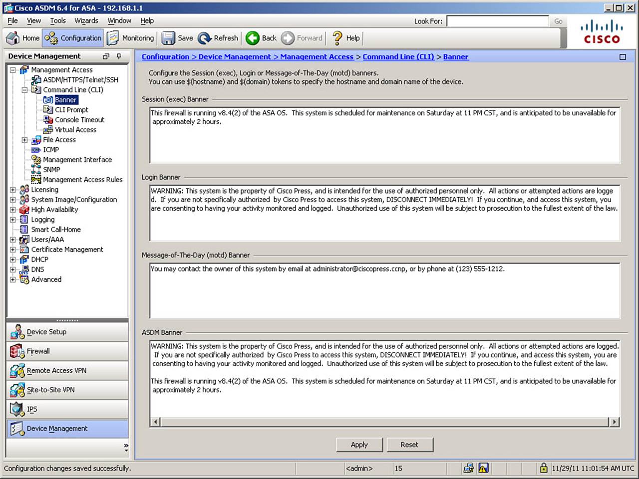
Figure 5-20. Configuring Management Access Banners
In Figure 5-20, all banner types are configured. Note the explicit nature of the warnings in the login banner, which include giving a connecting user the opportunity to disconnect immediately.
The CLI commands generated by the changes made are as follows:
no banner motd
banner motd You may contact the owner of this system by email at administra
tor@ciscopress.ccnp, or by phone at (123) 555-1212.
no banner exec
banner exec This firewall is running v8.4(2) of the ASA OS. This
system is scheduled for maintenance on Saturday at 11 PM CST, and is anticipated
to be unavailable for approximately 2 hours.
no banner login
banner login WARNING: This system is the property of Cisco Press, and is
intended for <...output omitted...>
no banner asdm
banner asdm WARNING: This system is the property of Cisco Press, and is intended
for <...output omitted...>
If you are configuring the ASA from the CLI, you can enter these commands directly in global configuration mode.
Note
The banners configured are merely examples and are not intended to imply “best practices.” For instance, the MOTD banner is seen by connecting users prior to successful login, so it is highly unlikely it would contain the administrator’s phone number. The login banner, on the other hand, contains all the elements previously discussed as desirable for full legal protection.
Controlling Management Access with AAA
The ASA uses its AAA subsystem to provide a user-based security model for access to its management interface, to user sessions crossing the firewall (cut-through proxy), and for remote access VPNs. This chapter discusses the first of those, using AAA to control management access.
The ASA has the capability to use a locally defined database for authentication and authorization purposes (note that there is no local accounting). It also supports a wide variety of external server types and protocols for full AAA support. External servers provide many potential benefits, such as centralized control, scalability (you have to create only one database of users to support a theoretically unlimited number of client systems), improved manageability, database mirroring, mass import/export of records, and integration with advanced and existing AAA methods.
The AAA server types supported by the ASA are as follows:
• Local database
• TACACS+
• RADIUS
• NTLM
• Kerberos
• LDAP
• SecurID
Although it is possible to use simpler administrative access control methods, it is strongly recommended that you use the AAA subsystem to control management access to the ASA. The use of the AAA subsystem allows you to use stronger authentication methods (with the use of external servers), implement a Role-Based Access Control (RBAC) system using authorization, reuse existing user authentication databases, implement strong auditing of management access (important for compliance with various regulations), and centralize all AAA functions.
AAA authorization requires an existing authentication configuration (it is not possible to know which privileges you have if the ASA cannot identify you). AAA accounting is possible without authentication, but it is of limited value without it (although it is possible to know that something was done without knowing who did it, it is certainly much more useful to know who did it).
To use the AAA subsystem to control management access to the ASA, you need to perform some or all of the following tasks:
• Create user objects in the local database. You can do this if you are using only locally defined administrator accounts, or as a fallback for times when communication to a central AAA database is not possible. (Having such a fallback is strongly recommended, as you might otherwise be unable to administer the ASA.)
• Configure local or remote administrator authentication information. At a minimum, this will include username, password, and associated privilege level.
• Configure a remote AAA server group and populate it with members. Available AAA features will depend on which type of server is defined. TACACS+ is preferred when configuring management access control due to its robust support for command authorization and accounting.
• Configure local or remote administrator authorization information. This allows you to control access to specific device management features and commands.
• Configure remote accounting for maintenance of a central auditing database.
Because there are so many possible combinations available within AAA configuration, this discussion is limited to a reasonable subset, to provide sufficient, albeit not exhaustive, coverage. As such, this section demonstrates how to configure the following scenario:
• An administrator account with a strong password and level 15 (highest level) access in the local database. This will be for fallback use if the remote AAA infrastructure is not available to the ASA, or for accessing the ASA via the Serial console.
• Authentication against the local database only, if accessing the Serial console port of the ASA. This is for illustration only, as centralized AAA would still be preferable for console access.
• Authentication against a TACACS+ server at 192.168.1.5, reachable through the “management” interface, for all remote management access sessions, with a fallback to the local database if this server is unreachable.
• Command and session authorization against the TACACS+ server, for all management access sessions (console or remote), with a fallback to the local database if this server is unreachable.
• Command and session accounting to the TACACS+ server, for all management access sessions.
Creating Users in the Local Database
To use local AAA authentication, or for local fallback in case remote, centralized AAA servers become unavailable, you must configure at least one user in the local database. The local database supports only password authentication (and not OTPs, tokens, and so on) and can be used to assign a privilege level to all locally defined users. A privilege level is a simple mechanism that allows differentiation of user access privileges and provides a simple method for multiple levels of management access. A privilege level defines which management functions and commands are available to a user. Privilege levels range from 0 (no access) to 15 (full administrative control). More information on privilege levels appears later, in the section, “Configuring AAA Command Authorization.”
It is recommended that you create at least one local administrator account, even if you intend to use remote AAA authentication on a regular basis. You will use this account in emergencies if communication to the central AAA servers fails, either because the servers are experiencing problems or because of network issues. This one account should be granted full administrative access, to ensure that it is not limited in its functionality should its use become necessary.
To create a local user database object, navigate to Configuration > Device Management > Users/AAA > User Accounts. The Add User Account window opens, as shown in Figure 5-21.
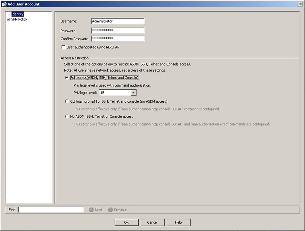
Figure 5-21. Adding User Accounts to Local AAA Database
Figure 5-21 shows creation of a user account. Enter a username—in this case, Administrator—in the Username field, and enter a sufficiently strong password in the Password and Confirm Password fields. Next, select the correct radio button for the level of access you want to give the user account. Because this example is configuring a full administrative access account, to be used as a fallback in case of remote AAA communication failure, click Full Access. When you choose Full Access, you should also set a specific Privilege Level. The default is 2, and in the absence of AAA command authorization, this level will provide full administrative access. Remember, however, that you want to ensure that this account is not limited in functionality, because it is intended for use in emergencies. Setting the level to 15 ensures that, even if AAA command authorization is configured on the ASA, this account will continue to have full administrative access. Therefore, the level is set to 15 in Figure 5-21.
Note that ASDM contains reminders that the other two settings are effective only if certain other commands are part of the ASA’s configuration. Assuming the correct commands are present, choosing CLI Login Prompt for SSH, Telnet and Console (No ASDM Access) is fairly self-explanatory—you are giving this local account access to the terminal, but not to ASDM. This might be necessary if you are using local command authorization (discussed later, in the section “Configuring AAA Command Authorization”) because an authenticated ASDM user has de facto level 15 access to the ASA. If you want to limit users to CLI access so you can limit their access to specific commands, this would be an appropriate setting.
The third option, No ASDM, SSH, Telnet or Console Access, might seem strange at first. Why create a local user account that has no access? The answer is, in case you use the local user database to authenticate VPN users. VPN support is not a subject covered in the FIREWALL exam, so it will not be discussed in this book, but that would be the purpose of a local user account with no administrative access.
To complete the creation of the local user account, click OK, and then click Apply to send the changes to the ASA.
The CLI command generated by the changes made is as follows:
username Administrator password loLkxe5el7hVzl6M encrypted privilege 15
If you are configuring the ASA from the CLI, you can enter this command directly in global configuration mode.
Note
Again, this is merely an example. In a production network, it is strongly recommended that you create a username that does not in itself identify this account as having super-user privileges. Therefore, usernames like “Admin,” “Administrator,” or “root” are strongly discouraged because they tend to be the first target for attackers.
Using Simple Password-Only Authentication
If there is no AAA authentication of any kind configured for the Telnet, SSH, or HTTP (ASDM) consoles, the ASA supports a simple password authentication method where all administrators use the same password (and in the case of SSH, the same username) to access the ASA. This is strongly discouraged as a mode of authentication. Setting the default Telnet and SSH passwords was already covered earlier in this chapter. By default, the configured enable password is used, without a username, for ASDM access.
Configuring AAA Access Using the Local Database
You can configure AAA authentication to any of the following five “consoles” for interactive management access to an ASA:
• Serial (the physical console port)
• Telnet
• SSH
• HTTP (actually HTTPS using ASDM)
• Enable (Setting AAA authentication on the Enable console requires a user to provide a username and password when moving from unprivileged mode to privileged mode and is an integral part of command authorization, as discussed later in the section, “Configuring AAA Command Authorization.”)
To enable AAA authentication on the consoles using the local database, navigate to Configuration > Device Management > Users/AAA > AAA Access. Figure 5-22 shows the resulting window.
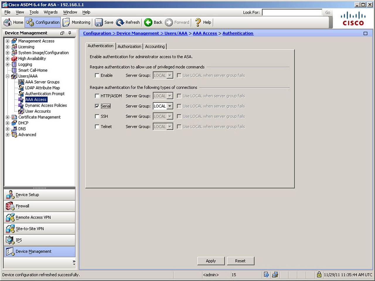
Figure 5-22. Configuring AAA Serial Console Authentication
Recall that the scenario in this section is that administrative access using the Serial console will be controlled using the local AAA database, as an illustration. As such, Figure 5-22 shows setting only the Serial console to use the local database for authentication. To do this, check the Serialcheck box, and then choose LOCAL in the drop-down box for the AAA server group. Click Apply to send the change to the ASA.
The LOCAL server group is the name used to refer to the locally configured user database. The LOCAL server group can never fail to be reached (similar to a router loopback interface). As such, it can only accept or reject authentication based on whether the user-names and passwords entered are correct. You can edit the properties of the LOCAL server group and set a maximum number of failed logins, after which the ASA can lock a local user account. To do so, navigate to Configuration > Device Management > Users/AAA > AAA Server Groups. Select the LOCAL server group, and click Edit to open the Edit LOCAL Server Group dialog box, shown in Figure 5-23.
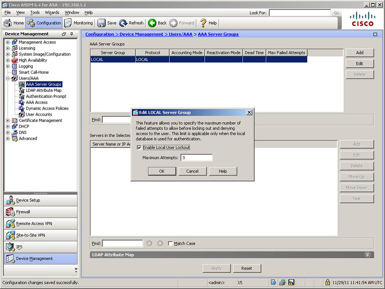
Figure 5-23. Enabling Local User Lockout
Figure 5-23 demonstrates enabling local user lockout. Check the Enable Local User Lockout check box, and set the number of failed attempts that will trigger locking of an account (the valid range is from 1 to 16). In Figure 5-23, this value is set to 3. Click OK, and then click Apply to send these changes to the ASA. This setting is available only for the LOCAL server group, as account locking following failed attempts is configured on the remote server if you are using remote AAA services.
The CLI commands generated by the changes made are as follows:
aaa authentication serial console LOCAL
aaa local authentication attempts max-fail 3
If you are configuring the ASA from the CLI, you can enter these commands directly in global configuration mode.
Note
The name LOCAL is case sensitive. Only LOCAL in all caps is recognized by the ASA as a reference to the local user database. Other database names can be in any mixture of case, at your discretion.
At this point, it is a good idea to test the user authentication using the LOCAL database, to ensure it works properly, before moving on to securing other management access channels. Remember, this is your fallback for situations where remote AAA server communication fails. If you fail to test it to ensure it works, and remote AAA server communication fails, you could end up locked out of your firewall, requiring password recovery to regain access. By performing this test prior to securing other management access channels, if anything goes wrong, you will temporarily be locked out from the Serial console port, but you will still have access to the ASA via Telnet, SSH, or HTTP/ASDM (depending on which is configured as allowed).
Testing of remote AAA servers is possible either from within ASDM or from the CLI using the test aaa-server command. Unfortunately, this is not supported for the LOCAL database. So, to test the LOCAL database, you need to connect to the ASA (in our example) using the Serial console and see if your authentication is successful.
Configuring AAA Access Using Remote AAA Server(s)
As mentioned earlier in this chapter, using a centralized server (or set of servers) for AAA control is preferable to using the local database. Configuring the use of remote AAA authentication on the ASA is a three-step process (additional configuration is necessary on the servers to be used for this function):
Step 1. Create a AAA server group, if none already exists, and configure how servers in the group are accessed (protocol, port, and how to determine if a server is failing communication).
Step 2. Populate the server group with member servers. Define the location of each server and assign a symmetric password, which will be used to encrypt the communication session (or portions thereof, depending on the protocol used) between the ASA and the remote AAA server. This same password must be configured on the server when defining the ASA as a AAA client.
Step 3. Enable user authentication for each remote management access channel (the consoles). Define which authentication server group will be used for each console upon which AAA authentication is enabled (note that you define a group here, not a specific server).
The sections that follow describe these steps in more detail.
Step 1: Create a AAA Server Group and Configure How Servers in the Group Are Accessed
To create a new AAA server group, navigate to Configuration > Device Management > Users/AAA > AAA Server Groups and click Add. The Add AAA Server Group dialog box opens, as shown in Figure 5-24.
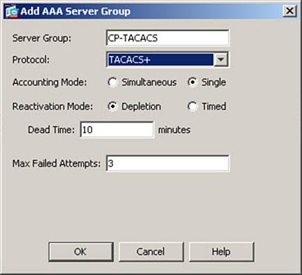
Figure 5-24. Creating a AAA Server Group
Figure 5-24 shows a new server group named CP-TACACS being created. TACACS+ is selected as the communication protocol to use with this server group. All other settings are left at their default settings.
If you choose a AAA accounting method, to be used if AAA accounting is configured (covered later, in the section, “Configuring Remote AAA Accounting”), the choices are Simultaneous, which means any accounting messages are sent to all servers in the selected group, and Single, which means one server in the group will act as the sole recipient of all AAA accounting records.
If a server is declared “dead” by the ASA, you can choose a Reactivation Mode for determining when it will be put back into the group’s active list of servers, for the ASA to attempt communication to it again. The default mode is Depletion, which means as soon as all servers that are members of this group are declared dead, they are all reactivated, and the ASA once again attempts to reach member servers in the order in which they are defined within the group. The other choice is Timed, which means a server will be declared dead for a predefined number of minutes and then automatically reactivated within the group. You define this time period in the Dead Time field.
At the bottom of the configurable fields is Max Failed Attempts. You can change the number of times the ASA should retry a member server before declaring the server dead. You configure on a per-server basis the number of seconds the ASA waits per attempt before a retry, as discussed later. Click OK to complete the creation of the new server group.
Step 2: Populate the Server Group with Member Servers
To populate the server group with member servers, select the AAA Server Group in the AAA Server Groups area, and then click Add in the Servers in the Selected Group area. The Add AAA Server dialog box opens, as shown in Figure 5-25.
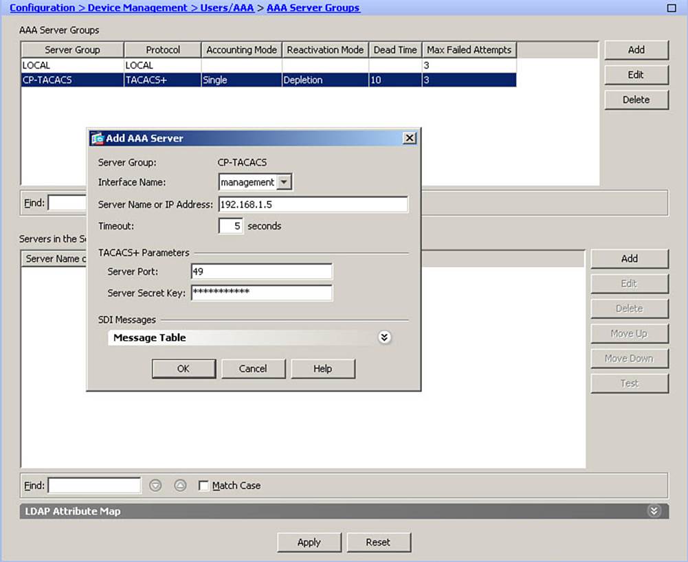
Figure 5-25. Adding a New AAA Server
For each server in a group, you must specify a location, IP address, and a symmetrical password used for session encryption. (This is a TACACS+ example; if you are using RADIUS, only user passwords are encrypted in the ASA-AAA server communication.) Optionally, you can adjust the default timeout per request, and set the port on which the server listens for AAA requests.
In Figure 5-25, a new server is defined as a member of the CP-TACACS group. The server is reachable through the ASA interface named management and has an IP address of 192.168.1.5. The timeout is set to 5 seconds per request, instead of 10. The default TCP port of 49 for TACACS+ is left unaltered, and the symmetrical password is set (the string is masked in the ASDM interface). Click OK, and then click Apply to complete the creation of the new member server.
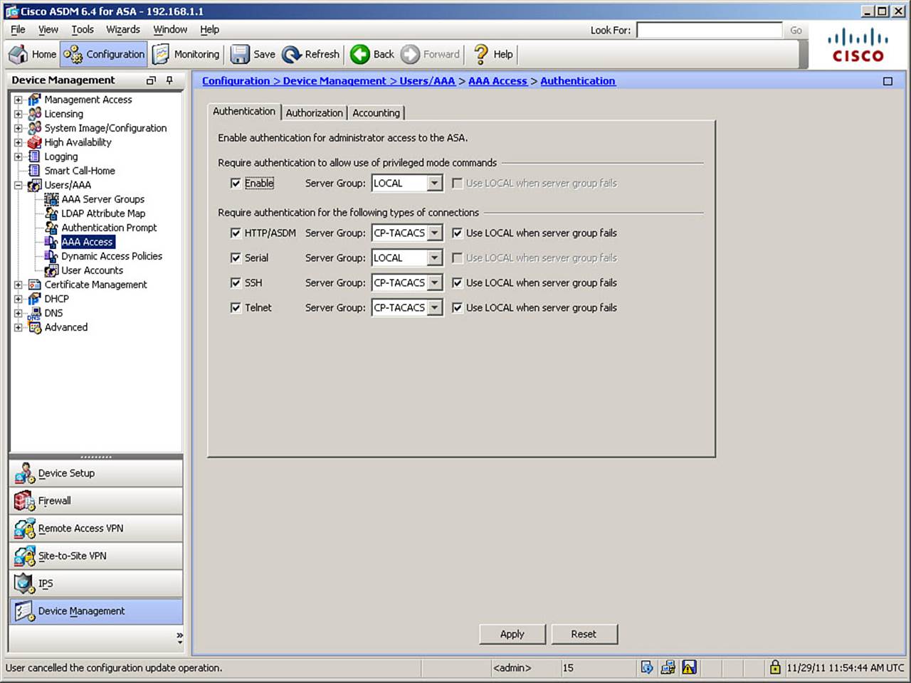
Figure 5-26. Configuring AAA Authentication
The CLI commands generated by the changes made are as follows:
aaa-server CP-TACACS protocol tacacs+
aaa-server CP-TACACS (management) host 192.168.1.5 key **********
timeout 5
If you are configuring the ASA from the CLI, you can enter these commands directly in global configuration mode.
Step 3: Enable User Authentication for Each Remote Management Access Channel
The final step is to configure AAA authentication using the new server group for each of the management access methods. In this scenario, it was decided to use remote AAA services for all consoles other than Serial and to set the use of the LOCAL server group for fallback, in case of failure of the remote AAA server group. To complete this process, navigate to Configuration > Device Management > Users/AAA > AAA Access once again, as shown in Figure 5-26.
In Figure 5-26, AAA authentication is configured on all consoles other than the Serial console, which was configured previously. In addition to enabling AAA authentication for each console, and selecting the newly configured AAA server group, the Use LOCAL When Server Group Fails check box is checked for each console. This means that if communication attempts by the ASA fail with all member servers in the selected group, remote AAA will be deemed to have failed, and the local database will be used for authentication. Note that the entry of an incorrect username or password is a failed authentication, not a failure of communication to the AAA server.
In Figure 5-26, the Enable console is set up to use server group LOCAL, due to the command authorization example in the next section.
Note
To authenticate console access, you may use any authentication protocol that is supported by the ASA AAA server groups, except the HTTP Form protocol, which is supported only in clientless SSL VPNs.
The CLI commands generated by the changes made are as follows:
aaa authentication enable console LOCAL
aaa authentication http console CP-TACACS LOCAL
aaa authentication ssh console CP-TACACS LOCAL
aaa authentication telnet console CP-TACACS LOCAL
If you are configuring the ASA from the CLI, you can enter these commands directly in global configuration mode.
Although the ASA is now configured to use a remote TACACS+ server for console authentication, this obviously will not function until you configure a remote TACACS+ server to accept such requests from the ASA, as described next.
Configuring Cisco Secure ACS for Remote Authentication
In the example, ASA is configured to use a remote TACACS+ server to perform authentication of remote management access. This server will be a Cisco Secure Access Control Server version 4.2. Because this book is focused on firewall configuration and troubleshooting, it covers only minimal information on Cisco Secure ACS—just enough to function as a server for AAA requests being sent by the firewall.
Figure 5-27 shows the Cisco Secure ACS window in which an ASA is defined as a AAA client. To access this window, navigate to the Network Configuration page in ACS, click the Not Assigned hyperlink under Network Device Groups, and then click Add Entry under the (Not Assigned) AAA Clients section of the resulting screen. Alternatively, you can create a network device group (NDG) for AAA clients if your organization chooses to use a NDG organization structure. The Add AAA Client pane opens.
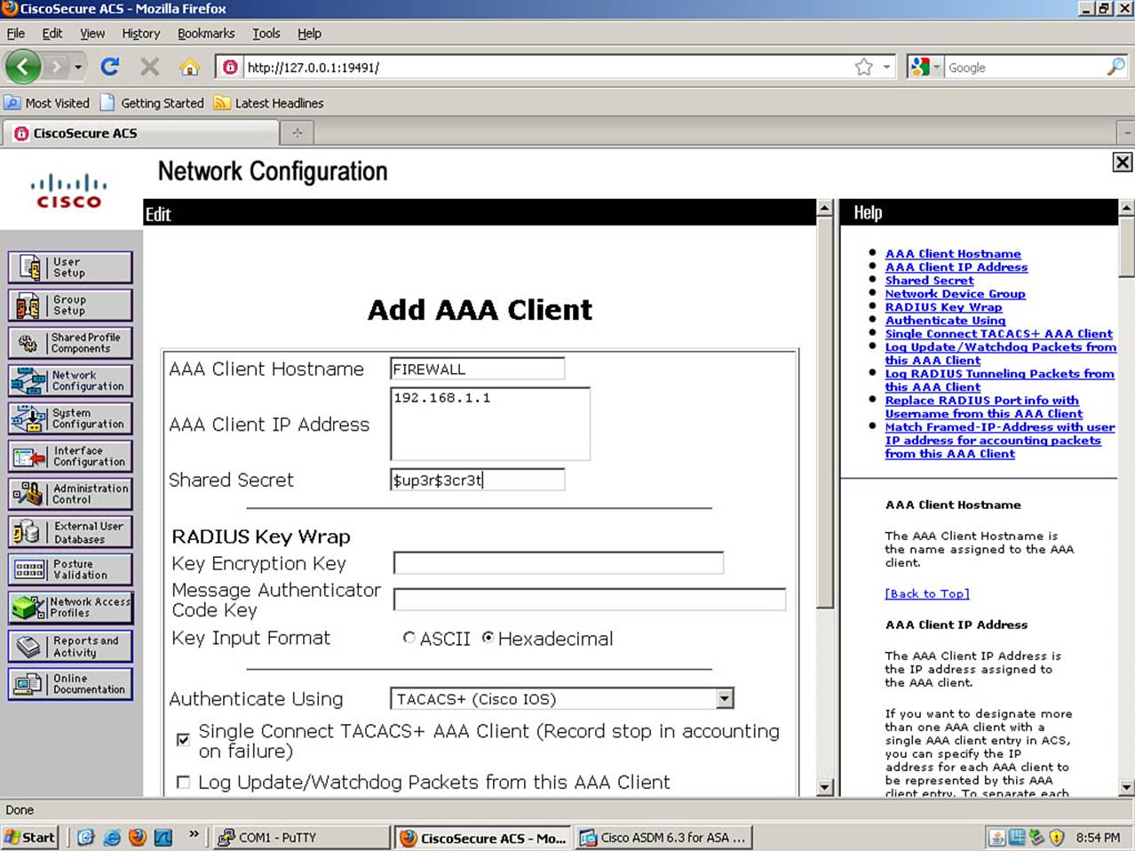
Figure 5-27. Defining a AAA Client in ACS
In the AAA Client Hostname box, enter the name for your ASA. Although this field does not have to match the configured hostname on your ASA, it is generally good practice to do so. In the AAA Client IP Address box, enter the IP address of the ASA interface that will generate AAA requests. For instance, if this AAA server is on the OOB management network connected to the Management0/0 interface of the firewall (as is the case in our example), enter the IP address 192.168.1.1, the ASA’s interface IP.
In a production environment, the symmetrical Shared Secret configured on the ASA and the AAA server should be very long and random. The reason is that this value is used as a seed to create the session encryption key used to safeguard communication between the ASA and this server. In our example, for the sake of expediency, it is set to a much simpler value of $up3r$3cr3t (SuperSecret, with common character substitutions).
In the Authenticate Using field, select the protocol used for communication of AAA requests/responses. In our example, select TACACS+ (Cisco IOS) for an ASA. Optionally, to create a persistent connection that will be used for future AAA requests (rather than renegotiating a new TCP handshake for each request), check the Single Connect TACACS+ AAA Client check box. Note that this applies only to TACACS+, not RADIUS, as RADIUS is a UDP protocol. When complete, click the Submit + Apply button at the bottom of the screen. (You must scroll down to see it.)
Now that the ASA is configured as a client on the AAA server, you must populate the AAA database with usernames, their passwords, and access privileges. To do so, click the User Setup button in Cisco Secure ACS 4.2.
Enter a new username in the User field, and click the Add/Edit button to open the User Setup screen, where you define a user database object, as shown in Figure 5-28.
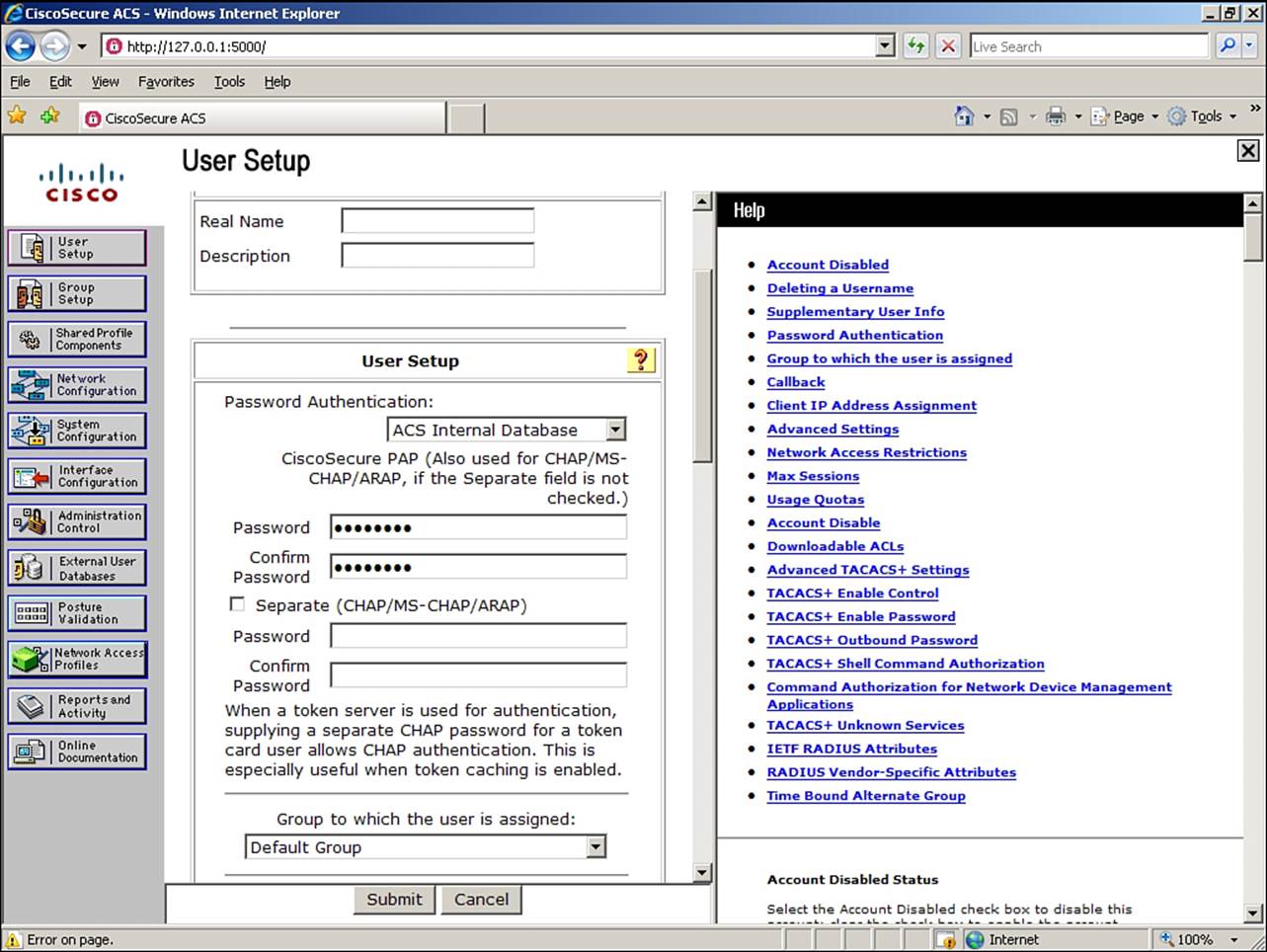
Figure 5-28. Adding a User in ACS
Add any optional details you choose, such as a real name and description. Select ACS Internal Database in the Password Authentication field. Enter and verify the password in plain text in the section labeled CiscoSecure PAP.
It is strongly recommended that you also configure password complexity rules within Cisco Secure ACS, to enforce the creation of strong passwords. For information on how to do this, consult the documentation for the Cisco Secure ACS product.
There are many other options that could be set for a user, and several become important if you are performing AAA command authorization using a remote AAA server. For now, however, you have configured everything necessary to perform AAA authentication for remote management access to the ASA, so click the Submit button at the bottom of the screen.
There are two ways to test communication with the remote AAA server from the ASA. From the CLI, use the test aaa-server command, entering the proper parameters for server group name, username, and password. You will be separately prompted for a specific server IP address. If you are using ASDM, navigate to the Configuration > Device Management > Users/AAA > AAA Server Groups window. Select a server from the lower pane, and click the Test button to the right. The Authentication radio button is selected by default. Enter a username and password, and click OK to test. Ensuring that configured users are successfully authenticated by your AAA servers is critical prior to configuring command authorization (covered in the next section).
Example 5-11 shows both a successful test and a failed test of AAA authentication.
Example 5-11. Testing AAA Authentication
FIREWALL# test aaa-server authentication CP-TACACS username Dave password
Z3br@Gr@yT
Server IP Address or name: 192.168.1.5
INFO: Attempting Authentication test to IP address <192.168.1.5> (timeout: 10
seconds)
INFO: Authentication Successful
FIREWALL# test aaa-server authentication CP-TACACS username Bob password Z3br@Gr@y
Server IP Address or name: 192.168.1.5
INFO: Attempting Authentication test to IP address <192.168.1.5> (timeout: 10
seconds)
ERROR: Authentication Rejected: Unspecified
Tip
If remote AAA communication fails when a user is authenticating for administrative access, the user attempting access is given no notification. As such, it can be difficult to determine that failure of remote AAA communication is the issue. If authenticating to the Serial, Telnet, or SSH console, the key is to watch carefully and note how long it takes to receive the Username prompt, how long after you enter your username you are prompted to enter your password, and how quickly you receive an Authentication Failure message after entering your password. If the Username prompt takes a long time to be displayed, but the Password prompt is immediate, and you get a failed authentication response almost instantaneously, your ASA is failing to communicate with the remote AAA server.
Configuring AAA Command Authorization
There are a number of approaches you can use for authorizing management functions on an ASA. Like AAA authentication, this can be done using either a local or remote authorization database, or by using both, with the local database acting as a fallback for the remote database. In our example, we will first configure the local authorization method, and then later change it to a fallback method after we’ve configured remote authorization.
All CLI commands (which are mapped to ASDM user interface functions) have an associated privilege level. Privilege levels are integers, between 0 and 15. Most commands by default are either privilege level 1 (commands executable from unprivileged mode) or privilege level 15 (commands requiring privileged mode for execution). An administrative user with a particular privilege level can execute all commands having a level up to and including the privilege level assigned to that user. For instance, a user with privilege level 15 can execute all commands (which is why we assigned user Administrator privilege level 15 in the previous section), but a user with privilege level 8 could only execute commands having levels 1 through 8.
By setting command privilege levels in a planned manner, you can therefore create multiple levels of administrative access, allowing you to implement an RBAC policy. Creating users and assigning privilege levels to them was covered in a previous section, “Creating Users in the Local Database.” Recall that the default privilege level for any newly created user is 2. The default behavior of privilege levels is as follows:
• Privilege level 0: Denies all access to management functions
• Privilege level 1: Allows CLI access only
• Privilege level 2: Allows CLI and ASDM access
Configuring Local AAA Command Authorization
To enable AAA authorization using the LOCAL database, you can use a wizard function in ASDM to quickly set up RBAC privilege levels to most commands, while still being able to make manual customizations to each command. To do so, navigate to Configuration > Device Management > Users/AAA > AAA Access and click the Authorization tab, shown in the background in Figure 5-29.
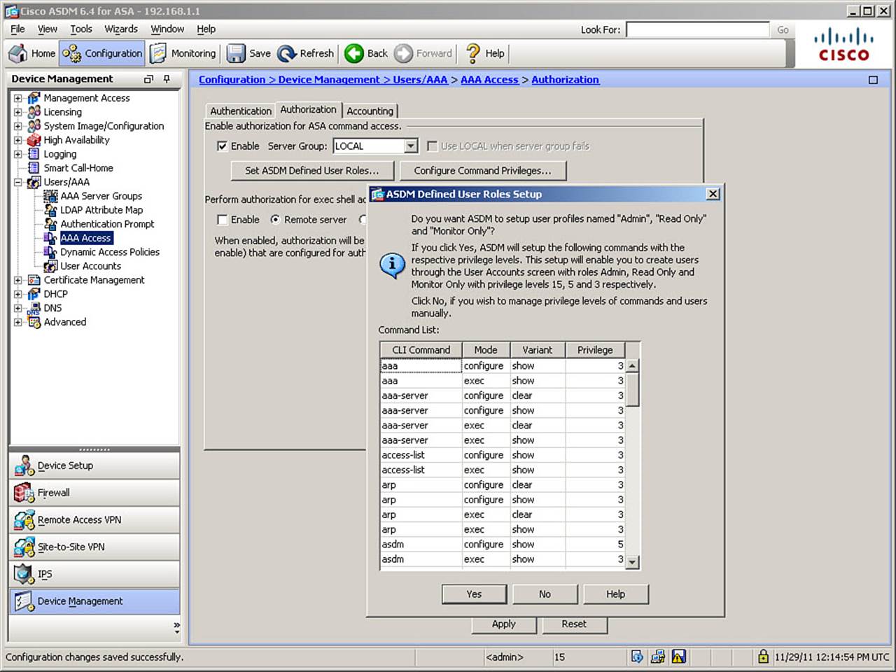
Figure 5-29. Defined User Roles Wizard
First, check the Enable check box. Enabling AAA command authorization has the effect that every time an administrative user enters a command (or attempts to use a feature in ASDM), the firewall will check that user’s privilege level against the configured level of the command they are attempting to use. If the user has sufficient privileges, the command will execute. If not, the user will receive a Command Authorization Failed error.
Leave LOCAL as the server group (which it is by default). To invoke the wizard, click the Set ASDM Defined User Roles button. Figure 5-29 shows the resulting dialog box. The three predefined roles, and their associated privilege levels, are as follows:
• Admin: Privilege level 15
• Read Only: Privilege level 5
• Monitor Only: Privilege level 3
As you can see, a wide range of ASA commands will be set to privilege level 3 (and a few to privilege level 5) if you click Yes, mapping them to the Monitor Only or Read Only roles, respectively. All other commands remain at their default privilege level.
Note
It is important that the database used for command authorization be the same as that used to authenticate to the Enable console. This is critical, as commands entered in privileged mode will be deemed to have been entered by the user who authenticated to the Enable console. If user Dave authenticated to the SSH console using server group CP-TACACS, but then authenticated as Administrator to the Enable console, using server group LOCAL, user Administrator is seen by the ASA as the issuer of commands being authorized.
After you have set up command privilege levels by using the wizard, you can customize command privilege levels by clicking the Configure Command Privileges button on the Authorization tab of the AAA Access window, which opens the Command Privilege Setup dialog box, shown inFigure 5-30.
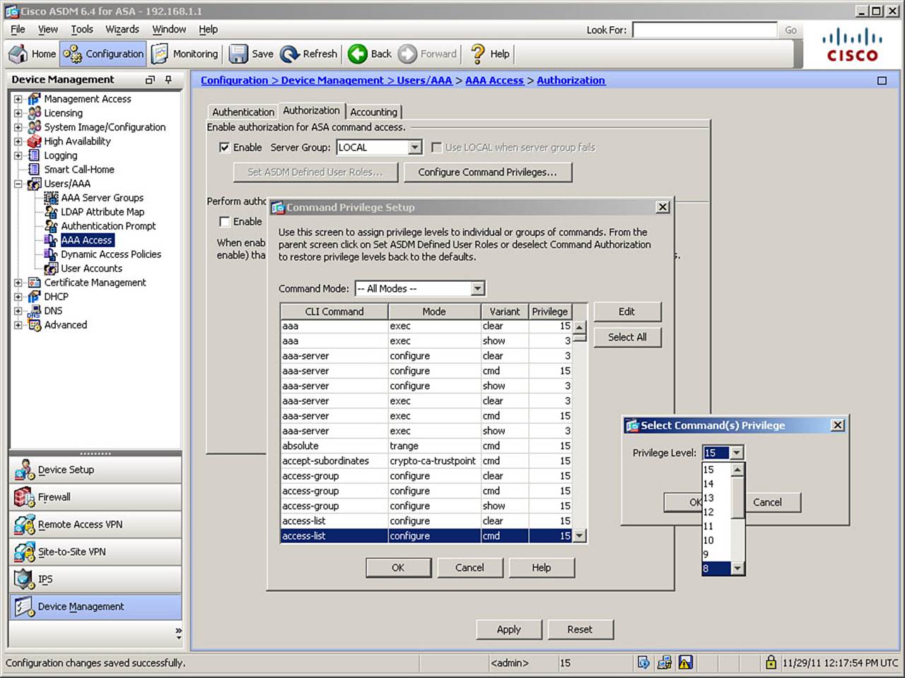
Figure 5-30. Customizing Command Privilege Levels
From the list of configurable commands, select a command to alter, and click Edit. In the resulting dialog box, also shown in Figure 5-30, click the selection arrow and choose a privilege level. The figure shows selecting a privilege level of 8 for the access list cmd variant (creating or editing an access list). Click OK twice, and then click Apply to complete the command customization.
The CLI commands generated by the changes made are as follows:
aaa authorization command LOCAL
privilege show level 3 mode configure command aaa
privilege show level 3 mode exec command aaa
privilege clear level 3 mode configure command aaa-server
privilege show level 3 mode configure command aaa-server
privilege clear level 3 mode exec command aaa-server
privilege show level 3 mode exec command aaa-server
privilege cmd level 8 mode configure command access-list
privilege show level 3 mode configure command access-list
privilege show level 3 mode exec command access-list
privilege clear level 3 mode configure command arp
privilege show level 3 mode configure command arp
privilege clear level 3 mode exec command arp
privilege show level 3 mode exec command arp
privilege show level 5 mode configure command asdm
privilege show level 3 mode exec command asdm
privilege show level 3 mode exec command asp
privilege show level 3 mode exec command blocks
privilege show level 3 mode configure command clock
privilege show level 3 mode exec command clock
privilege show level 3 mode exec command compression
privilege show level 3 mode exec command cpu
privilege clear level 3 mode configure command crypto
privilege show level 3 mode configure command crypto
privilege clear level 3 mode exec command crypto
privilege show level 3 mode exec command crypto
privilege show level 3 mode configure command dhcpd
privilege show level 3 mode exec command dhcpd
privilege clear level 3 mode exec command dns-hosts
privilege show level 3 mode exec command dns-hosts
privilege clear level 3 mode exec command dynamic-filter
privilege show level 3 mode exec command dynamic-filter
privilege show level 3 mode exec command eigrp
privilege cmd level 3 mode configure command failover
privilege show level 3 mode configure command failover
privilege cmd level 3 mode exec command failover
privilege show level 3 mode exec command failover
privilege show level 3 mode exec command firewall
privilege show level 5 mode exec command import
privilege show level 3 mode configure command interface
privilege show level 3 mode exec command interface
privilege show level 3 mode configure command ip
privilege show level 3 mode exec command ip
privilege show level 3 mode exec command ipv6
privilege clear level 3 mode configure command logging
privilege show level 3 mode configure command logging
privilege clear level 3 mode exec command logging
privilege cmd level 3 mode exec command logging
privilege show level 3 mode exec command logging
privilege show level 3 mode exec command mode
privilege show level 3 mode exec command module
privilege show level 3 mode exec command ospf
privilege cmd level 3 mode exec command packet-tracer
privilege cmd level 3 mode exec command perfmon
privilege cmd level 3 mode exec command ping
privilege show level 5 mode configure command privilege
privilege show level 3 mode exec command reload
privilege show level 3 mode configure command route
privilege show level 3 mode exec command route
privilege show level 5 mode exec command running-config
privilege show level 3 mode configure command ssh
privilege show level 3 mode exec command ssh
privilege show level 3 mode exec command uauth
privilege show level 3 mode exec command vlan
privilege show level 3 mode exec command vpn
privilege show level 3 mode exec command vpn-sessiondb
privilege show level 3 mode exec command wccp
privilege show level 3 mode exec command webvpn
privilege cmd level 3 mode exec command who
If you are configuring the ASA from the CLI, you can enter these commands directly in global configuration mode. The customized command is highlighted for reference.
Note
If you set command privilege levels for the configuration command (mode configure), it is imperative that the users have sufficient privileges to execute the configure terminal command. By default, this remains a level 15 command, so even if a user has privilege level 8, for example, and the configure access-list privilege level is set to 8, as in the example, the user cannot configure access lists until you first make configure terminal a level 8 or lower command. The required syntax to do so is privilege cmd level 8 mode exec command configure.
Configuring Remote AAA Command Authorization
You can also enable command authorization using a remote TACACS+ server group. You should first configure all command authorization parameters on the AAA server because once you activate this feature on the ASA, any commands that you try to issue are immediately rejected if not part of the authorized command set configured on the AAA server. It is also recommended that you configure the use of the LOCAL database as a fallback, and configure at least one username in the local database with privilege level 15 access, in case of remote server communication failure. Note that only the TACACS+ protocol supports command authorization.
The configuration of command authorization on a Cisco Secure ACS server will not be covered in detail in this book. However, it can be reached in ACS by navigating to Shared Profile Components > Shell Command Authorization Sets. One Shell Command Authorization Set is created per profile (for example, Admin, View Only, and so on). Within each set, you are allowed to specify commands and command parameters to be explicitly permitted or denied, and also whether to permit or deny any commands or command parameters not explicitly configured.
Note
It might seem odd that you use Shell Command Authorization Sets, and not PIX/ASA Command Authorization Sets, which is an available option under Shared Profile Components. PIX/ASA Command Authorization Sets were used with software versions prior to 8.0. With software versions 8.0 and higher, Shell Command Authorization Sets are used.
After you have configured command authorization sets, you edit user or group records within ACS, granting them shell access (authorization to enter privileged mode) and assigning them a Shell Command Authorization Set, which defines which commands they are allowed to use. This can be done for all AAA clients of the ACS server (firewalls, routers, switches, and so on), or by sorting AAA clients into network device groups. Figure 5-31 shows an example of assigning a shell command authorization set for all AAA client devices.
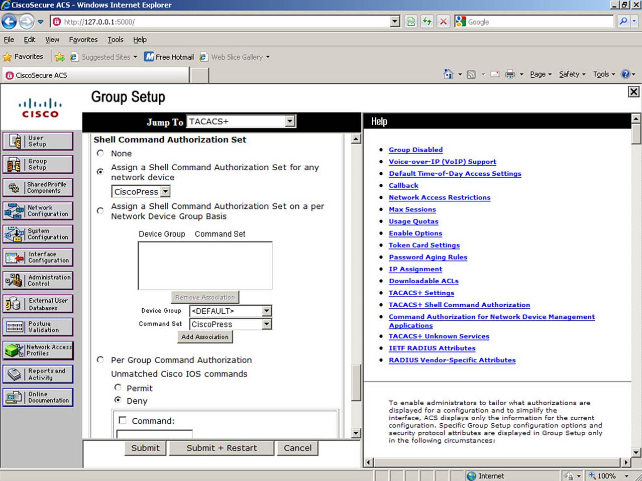
Figure 5-31. Assigning a Shell Command Authorization Set to Group
It is recommended that you always apply permissions to groups, rather than to individual users, for scalability and ease of use, unless you have specific requirements for some users to have specialized access rights. In the figure, a group has been granted Shell access and assigned the shell command authorization set named CiscoPress.
Note
Preliminary configuration of the Cisco Secure ACS interface options is necessary before these options will become available for configuration. Please refer to documentation for the ACS product for complete instructions. Also, other options on ACS are relevant to command authorization. Although not relevant to the FIREWALL exam, this is one of the most maddeningly difficult configuration issues that the author has repeatedly been asked about. Therefore, the following ACS configuration is necessary for remote AAA command authorization to function properly:
1. Click the Interface Configuration button, and then TACACS+ (Cisco).
2. Scroll down and check the Advanced TACACS+ Features check box, and then click Submit.
3. Return to Group Setup, select the correct group, and click Edit Group Settings.
4. Under the Enable Options heading, set the Max Privilege Level to 15, either for any AAA client, or per Network Device Group, if you are using them. Finally, click the Submit + Restart button at the bottom of the screen.
5. For each user you want to use Command Authorization, edit his profile on the ACS Server. After the Interface Configuration changes are made, there will be a new section available: Advanced TACACS+ Settings. Within this section, under the TACACS+ Enable Control heading, select the Use Group Level Setting radio button. Then, under the TACACS+ Enable Password heading, select what password this user will use to enter privileged mode. Finally, click the Submit button at the bottom of the screen.
Only after all these steps are completed will remote AAA Command Authorization function properly.
After you have configured the remote AAA server with proper settings, you must configure the ASA to check for user authorizations, using the appropriate AAA server group. To do so, return to Configuration > Device Management > Users/AAA > AAA Access, and then click theAuthorization tab, as shown in Figure 5-32.
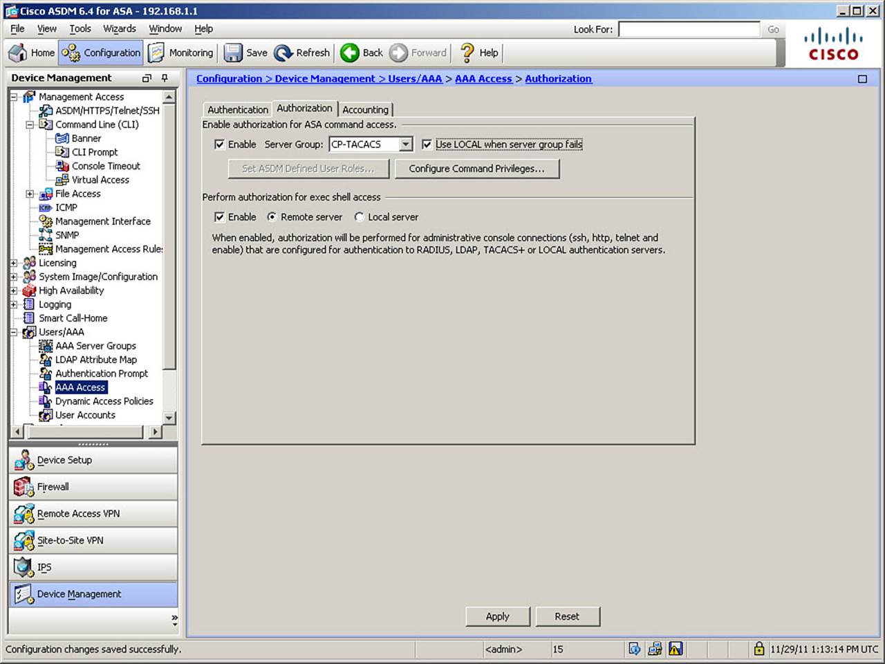
Figure 5-32. Configuring Remote AAA Command Authorization
Figure 5-32 shows the changes from the previous example that are necessary to redirect command authorization queries to a remote AAA server group instead of to the local database. The box is still checked to enable command authorization, but this time, the CP-TACACS server group is selected, and the local database is selected as a fallback method.
In addition to performing command authorization, it is possible to separately authorize shell access. This feature allows you to prevent users without the shell access privilege from being able to log into the ASA and gain CLI access (the ability to distinguish network users from device administrators). Note that gaining access is different from being able to execute commands, which is why this is a separate feature. Figure 5-32 also shows this separate authorization check being enabled, and the selection of the remote server to perform the check. This automatically performs the check against the same server group that performed the original user authentication. If only this option is enabled, then remotely defined user privilege levels are used along with locally defined command privilege levels, to determine user command authorization.
If you configure the ASA to perform command authorization using a TACACS+ server, it is imperative that the Enable console authentication be performed using TACACS+. If a TACACS+ server is not used for Enable console authentication, then the user successfully gaining access to privileged EXEC mode is known to the ASA only as the “enable_15” (system default privileged username) user. The ASA would thus send authorization requests to the TACACS+ server as user enable_15 attempting to perform commands. Because it is highly unlikely that a TACACS+ server would have an enable_15 user defined, all command authorization requests would fail. Configuring Enable console authentication to use TACACS+ would ensure the proper username is sent to the TACACS+ server for subsequent command authorization requests.
Once these changes are made, click Apply to finish activating remote command authorization.
The CLI commands generated by the changes made are as follows:
aaa authorization command CP-TACACS LOCAL
aaa authorization exec authentication-server
If you are configuring the ASA from the CLI, you can enter these commands directly in global configuration mode.
Configuring Remote AAA Accounting
The ASA remote AAA accounting feature supports recording of specific events to a centralized AAA server or group of servers. You can audit access to privileged mode (enable console access), audit when administrative users gain Serial, Telnet, or SSH console access to the ASA via RADIUS or TACACS+, or audit the execution of individual commands via TACACS+ only. If auditing command execution, you set a privilege level to be recorded. All executions of commands having the configured privilege level or a higher level are recorded to the AAA Accounting log. To configure AAA accounting, navigate to Configuration > Device Management > Users/AAA > AAA Access and then click the Accounting tab, shown in Figure 5-33.
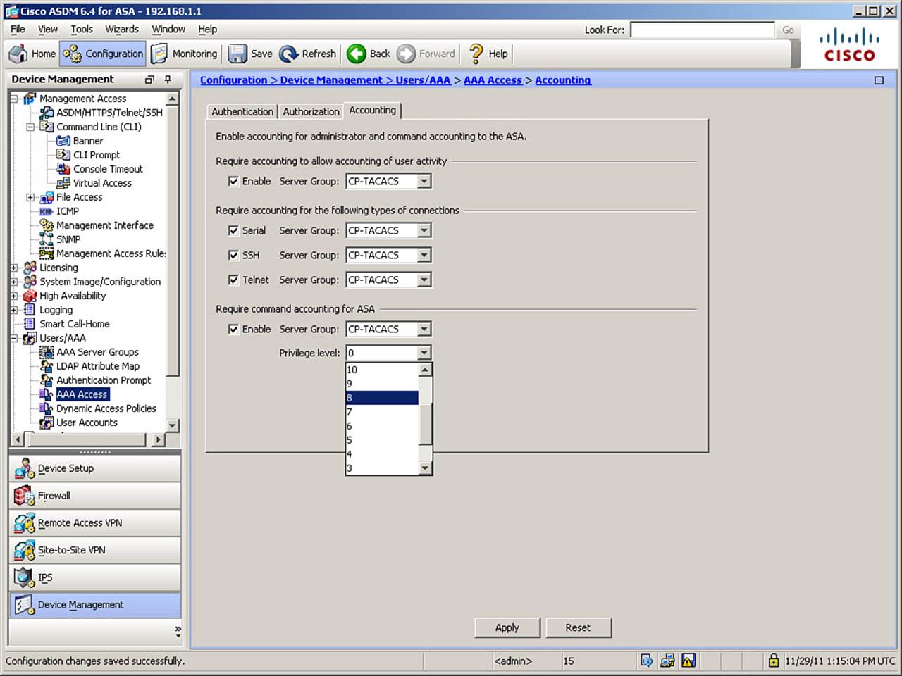
Figure 5-33. Configuring AAA Accounting
In Figure 5-33, all accounting options are enabled, with log messages being sent to the CP-TACACS server group. Remember that whether accounting messages are sent to a single server or to all group members is configured as part of creating the server group.
Check the Enable check box in the Require Accounting to Allow Accounting of User Activity area, which activates accounting of access to the Enable console (entry into privileged mode). Access to the Serial, SSH, and Telnet consoles can be logged by checking the appropriate check boxes.
To record successful or failed attempts to execute specific commands (incomplete or otherwise invalid commands and “typos” are not logged), check the Enable check box in the Require Command Accounting for ASA area. When this option is enabled, you will also want to select a Privilege Level option, which will record all desired command execution.
In Figure 5-33, privilege level 8 is selected, which will cause all commands having privilege level 8 or higher to be logged. The selected level should be based on your local security policy. For instance, most organizations would want to record only commands that change the ASA configuration, and not commands that only monitor activity (such as show commands). Other organizations require the recording of all command activity.
The CLI commands generated by the changes made are as follows:
aaa accounting enable console CP-TACACS
aaa accounting serial console CP-TACACS
aaa accounting ssh console CP-TACACS
aaa accounting telnet console CP-TACACS
aaa accounting command privilege 8 CP-TACACS
If you are configuring the ASA from the CLI, you can enter these commands directly in global configuration mode.
Verifying AAA for Management Access
When using AAA servers, you can easily verify successful communication between your ASA and the AAA server by observing the AAA server status and statistics, using the show aaa-server command. As Example 5-12 demonstrates, this command displays the server group to which a server belongs, the protocol used by the server group for AAA exchanges, the IP address of the server, the current status (active or inactive) of the AAA server, and statistics about AAA exchanges (requests and responses).
Example 5-12. Viewing AAA Server Statistics
FIREWALL# show aaa-server
Server Group: LOCAL
Server Protocol: Local database
Server Address: None
Server port: None
Server status: ACTIVE, Last transaction at 13:07:14 UTC Tue Nov 29 2011
Number of pending requests 0
Average round trip time 0ms
Number of authentication requests 33
Number of authorization requests 0
Number of accounting requests 0
Number of retransmissions 0
Number of accepts 4
Number of rejects 29
Number of challenges 0
Number of malformed responses 0
Number of bad authenticators 0
Number of timeouts 0
Number of unrecognized responses 0
Server Group: CP-TACACS
Server Protocol: tacacs+
Server Address: 192.168.1.5
Server port: 49
Server status: ACTIVE, Last transaction at 13:36:34 UTC Tue Nov 29 2011
Number of pending requests 0
Average round trip time 3ms
Number of authentication requests 47
Number of authorization requests 115
Number of accounting requests 4
Number of retransmissions 0
Number of accepts 125
Number of rejects 38
Number of challenges 15
Number of malformed responses 0
Number of bad authenticators 0
Number of timeouts 3
Number of unrecognized responses 0
The test aaa-server command is the other principal method of verifying AAA functionality. Due to the importance of verifying successful authentication prior to configuring command authorization, this command was discussed and demonstrated earlier in this chapter.
Configuring Monitoring Using SNMP
The Cisco ASA supports network monitoring using SNMP versions 1, 2c, and 3 (not supported prior to OS version 8.2), and supports any combination of those being used simultaneously (that is, different monitoring platforms using different versions). As stated earlier, the ASA supports SNMP read-only access through the use of SNMP GET requests. SNMP write access is not allowed, so using SNMP SET requests or attempting to modify the configuration in any way using SNMP is not permitted.
The ASA can be configured to send SNMP traps, which are unsolicited messages from the managed device to a network management system (NMS) for certain events (event notifications). You can also use an NMS to browse the Management Information Bases (MIB) on the ASA. A MIB is a collection of information definitions, and the ASA maintains a database of values for each definition. Browsing a MIB requires using an NMS to determine values by issuing a series of GET-NEXT and/or GET-BULK requests of the MIB tree.
SNMP on the ASA requires client authentication. With SNMP version 1 or 2c, this is done by the NMS sending the proper community string (a password, sent in clear text) with its request. Such community strings can be set either as a default or uniquely per NMS IP address. SNMP version 3 can use strong, cryptographic protection for its information exchanges, and/or a combination of username and key for authentication.
To configure the ASA to permit NMS polling or sending of SNMP traps to an NMS, navigate to Configuration > Device Management > Management Access > SNMP to open the SNMP configuration window, shown in Figure 5-34.
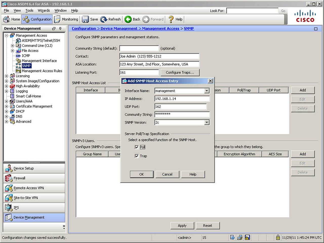
Figure 5-34. SNMP Configuration Window
If the Community String (Default) field is left blank, this ASA will be configured with specific community strings on a per-IP-address basis. Contact and location information is entered only once, if completed, because this information refers to the ASA itself and does not change on a per-management-station basis. This ASA will listen on the default SNMP polling port of UDP 161, unless changed.
To add an NMS definition, click the Add button in the SNMP Management Stations area. This opens the Add SNMP Host Access Entry dialog box. If you are editing or deleting existing configured NMS definitions, use the Edit or Delete key. When adding or editing, configure the NMS definition according to the settings in your network. In Figure 5-34, the OOB management network attached to interface management is selected. The NMS IP address of 192.168.1.14 is defined. The default SNMP trap port of UDP 162 is left unaltered, a unique community string is defined for this NMS host, and the SNMP version is selected as version 2c.
Note that you can configure an SNMP host to perform polling, receive traps, or both by checking the appropriate box in this dialog box. Both choices are checked by default, as shown in Figure 5-34. Complete the NMS definition by clicking OK. If you select an interface other than “inside” for the sending of SNMP traps, you receive a warning message that this might be insecure. Acknowledge the message and complete the configuration by clicking Apply.
The CLI commands generated by the changes made are as follows:
snmp-server location 123 Any Street, 2nd Floor, Somewhere, USA
snmp-server contact Joe Admin (123) 555-1212
snmp-server host management 192.168.1.14 community SNMP1234 version 2c
If you are configuring the ASA from the CLI, you can enter these commands directly in global configuration mode.
The ASA can be configured to send several types of SNMP traps. If your local policy dictates, click the Configure Traps button in the SNMP configuration window to open the SNMP Trap Configuration dialog box, shown in Figure 5-35.
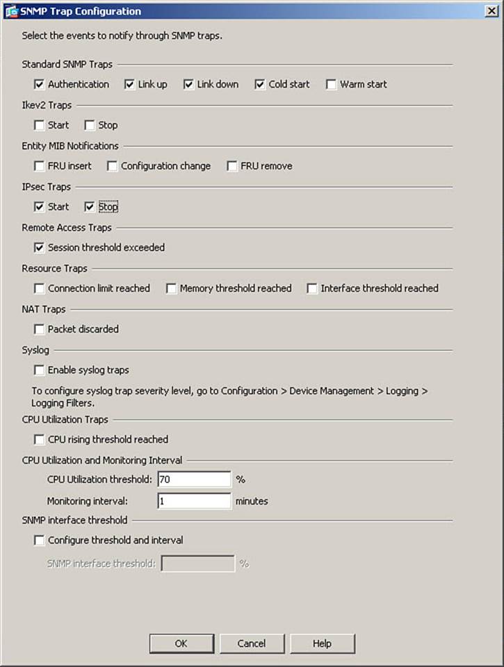
Figure 5-35. IDS and IPS Operational Differences
In Figure 5-35, in addition to the four standard SNMP traps (which are enabled by default), traps are enabled for IPsec Start and Stop and for Remote Access Session Threshold Exceeded. Complete the traps configuration by clicking OK and then clicking Apply. If you want to send SNMP traps as syslog messages, in addition to enabling syslog traps within the SNMP Trap Configuration screen, you need to configure a logging filter and destination in order to send traps (as syslog messages) to a configured syslog server. Configuration of logging is covered in Chapter 6, “Recording ASA Activity.”
The CLI commands generated by the changes made are as follows:
snmp-server enable traps ipsec start
snmp-server enable traps ipsec stop
snmp-server enable traps remote-access session-threshold-exceeded
If you are configuring the ASA from the CLI, you can enter these commands directly in global configuration mode.
If you are using SNMP version 3, you will need to configure SNMPv3 users and groups. This is the major difference between SNMPv3 and earlier versions. Groups define the protection model used for communication between the ASA and the NMS. The definition of groups and users allows for highly granular control over access to the SNMP agent and MIB objects.
Three SNMPv3 group definitions are supported by the ASA:
• No Authentication, No Encryption: Cleartext communication between the ASA and NMS
• Authentication Only: Communication is authenticated but unencrypted
• Authentication and Encryption: Authentication and full encryption for communication between the ASA and NMS
To use authenticated and/or encrypted communication, you need to configure the cryptographic keys and choose algorithms to authenticate and/or encrypt SNMP packets. These are symmetric keys and must be defined on both the ASA and the NMS.
To configure new SNMPv3 user information, from the SNMP configuration window, click Add in the SNMPv3 Users area to open the Add SNMP User Entry dialog box, shown in Figure 5-36. If you are editing or deleting existing configured users, use the Edit or Delete button.
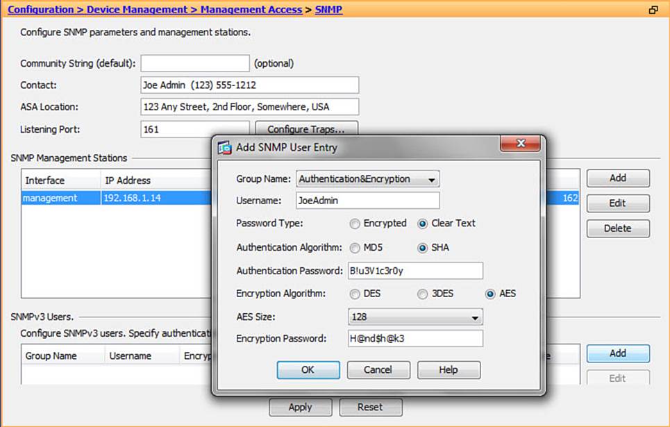
Figure 5-36. Adding SNMPv3 User Information
In this case, an SNMPv3 group name of Authentication and Encryption is selected. The remote username is configured, and Clear Text is selected for Password Type. If Encrypted is selected here, both password fields must be completed with hexadecimal strings, in the format xx:xx:xx:.... Because Clear Text is selected, a plaintext password is entered for the password to be used with the selected Authentication Algorithm (you should prefer SHA over MD5). If AES is selected as the Encryption Algorithm, you must also select the size of the AES key, either 128-, 192-, or 256-bit (AES or 3DES is recommended). The encryption password is then entered, either in plaintext or hexadecimal format, once again depending on the Password Type selected. A maximum of 64 characters is allowed for either password. Complete the addition of the new user by clicking OKand then clicking Apply.
The CLI commands generated by the changes made are as follows:
snmp-server group Authentication&Encryption v3 priv
snmp-server user JoeAdmin Authentication&Encryption v3 auth B!u3V1c3r0y priv AES
128 H@nd$h@k3
If you are configuring the ASA from the CLI, you can enter these commands directly in global configuration mode.
The full syntax and options of the snmp-servers group command are as follows:
snmp-server group group-name {v3 {auth | noauth | priv }}
• auth: Specifies packet authentication without encryption.
• group-name: Defines the name of the group.
• noauth: Specifies no packet authentication or encryption.
• priv: Specifies both packet authentication and encryption.
• v3: Specifies the group is using the SNMP v3 security model, which is the most secure of the supported security models. This version allows you to explicitly configure authentication characteristics.
The full syntax and options of the snmp-server user command are as follows:
snmp-server user username group-name {v3 [encrypted] [auth { md5 | sha} auth-pass
word]} [priv {des | 3des | aes {128 | 192 | 256}} priv-password ]
• 128 | 192 | 256: Specifies the number of bits used by the AES algorithm for encryption.
• auth: Specifies which authentication algorithm should be used, when using authentication.
• auth-password: Specifies the string that enables the agent to receive packets from the ASA. The maximum length is 64 characters. You can specify a plaintext password or localized digest. The digest must be formatted as xx:xx:xx..., where xx are hexadecimal values. The digest should be exactly 16 octets in length.
• des | 3des | aes: Specifies encryption algorithm.
• encrypted: Specifies that the passwords appear in digest format, rather than plaintext.
• group-name: Specifies the name of the group to which the user belongs.
• md5 | sha: Specifies the authentication algorithm.
• priv-password: Specifies a string as the privacy user password. The maximum length is 64 characters. You can specify a plaintext password or a localized digest. The digest must be formatted as xx:xx:xx..., where xx are hexadecimal values. The digest should be exactly 16 octets in length.
• username: Specifies the name of the user on the host that connects to the agent.
• v3: Specifies that the SNMP Version 3 security model should be used. Allows the use of the encrypted, priv, and auth keywords.
Troubleshooting Remote Management Access
Most issues with remote management access appear in the ASA system log (or remote syslog server) depending on the severity level. Use the show logging command, use the ASDM real-time log viewer, or examine your centralized log files for such messages.
Some examples follow:
%ASA-3-710003: TCP access denied by ACL from 10.10.5.12/6724 to
inside:10.0.0.1/22
The preceding message indicates that management access rules do not permit the management session.
%ASA-3-315004: Fail to establish SSH session because RSA host key retrieval failed.
%ASA-3-315011: SSH session from 192.168.1.8 on interface management for user ""
disconnected by SSH server, reason: "Internal error" (0x00)
This message pair indicates that the local RSA key pair has not been generated, as required for the ASA SSH server.
If system log messages do not pinpoint the issue, consider debugging management protocols on the ASA, such as the following (note that some of these commands support different levels of debugging):
• debug ssh: Debugs the SSH daemon to determine low-level protocol failures, such as algorithm or version incompatibility
• debug http: Debugs HTTP exchanges to determine problems with the ASDM image
• debug snmp: Debugs SNMP exchanges to help determine problems with SNMP authentication and OIDs
To troubleshoot AAA for management access, you have to troubleshoot activity on both the ASA and, in the case of remote AAA, the AAA server.
The recommended troubleshooting task flow when troubleshooting local or remote AAA is as follows:
Step 1. For remote AAA, verify mutual reachability between the ASA and the server using ping, traceroute, show aaa-server, or similar tools. Also, verify that symmetrical session keys (shared secret) are used in the AAA protocol association.
Step 2. Verify the status of AAA authentication requests. Use show logging, debug aaa authentication, debug tacacs, and debug radius on the ASA. On the remote server, view failure reports and check for locked user accounts.
Step 3. Verify the AAA authorization process. In addition to the previously mentioned commands, use debug aaa authorization. Check the failure reports and verify user or group privileges on remote AAA servers.
Step 4. Verify that AAA accounting messages are properly being sent by the ASA, using the debug aaa accounting command, and received on the AAA server, by viewing its accounting reports.
The ASA logs many system messages related to the AAA subsystem. By using the show logging command, using the ASDM real-time log viewer, or examining logs in a centralized logging or management system, you may be able to pinpoint the cause of AAA issues.
Some examples follow:
%ASA-6-113015: AAA user authentication Rejected : reason = Invalid password :
local database : user = Administrator
The preceding message indicates that authentication failed due to bad credentials.
%ASA-6-113014: AAA authentication server not accessible : server = 192.168.1.5 :
user = Dave
%ASA-2-113022: AAA Marking TACACS+ server 192.168.1.5 in aaa-server group CP-
TACACS as FAILED
This message pair indicates that user authentication failed due to server communication failure.
%ASA-6-113004: AAA user authentication Successful : server = 192.168.1.5 :
user = Dave
%ASA-6-113005: AAA user authorization Rejected : reason = User was not found :
user = Dave
This message pair indicates that the user was not found in the authorization database (note that remote AAA was used for authentication, but authorization is checked against the local database).
Finally, you can debug protocol-level details to troubleshoot possible compatibility issues between your ASA and a remote AAA server by using the debug tacacs or debug radius commands. You can specify conditional debugging (such as limiting to a single username) to avoid excessive output and performance issues. Because much of the output uses terms that are unique to TACACS+ (“verbs”) and RADIUS (“attributes”), knowledge of these terms are necessary to properly interpret the debug output.
Unlocking Locked and Disabled User Accounts
A user account is normally locked when a configurable threshold of successive and unsuccessful login attempts have been made using that account.
If a local database user account becomes locked, and you need to unlock it, within ASDM, navigate to Monitor > Properties > Device Access > AAA Local Locked Out Users, as shown in Figure 5-37.
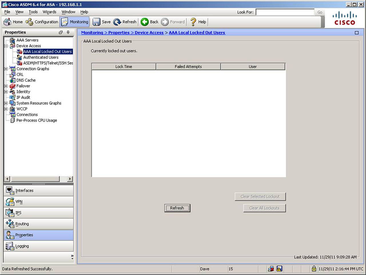
Figure 5-37. Unlocking Local User Accounts
If any local user accounts appear in the list of locked accounts, you may either select one account name and click the Clear Selected Lockout button to unlock a single account, or simply click the Clear All Lockouts button to remove the lock from all accounts.
Cisco ASA Password Recovery
If you lose the ability to gain management access to the ASA, either due to loss of necessary passwords or due to accidental lockout from the incorrect application of AAA functions, you can regain access to the ASA using a special procedure that can be performed only through the Serial console. Although this procedure is referred to as password recovery, it is not actually possible to “recover” lost passwords. Instead, you replace previously set passwords with new ones of your choosing.
Performing Password Recovery
To perform password recovery, connect to the serial console port of the ASA. Power cycle the ASA and watch the messages during boot. Two messages will appear, as follows:
Use BREAK or ESC to interrupt boot.
Use SPACE to begin boot immediately.
A 10-second countdown appears directly below these messages. Press the Esc key to interrupt the boot process and enter ROM Monitor (ROMMON) mode. From ROMMON mode, you set the configuration register value to instruct the ASA to bypass its startup configuration file (where passwords and AAA commands are stored), and reboot it. Example 5-13 shows the full procedure.
Example 5-13. Performing Password Recovery
rommon #0> confreg 0x41
rommon #1> boot
Loading disk0:/asa823-k8.bin...
<...output omitted...>
ciscoasa> enable
Password: <press Enter>
ciscoasa# copy startup-config running-config
FIREWALL# configure terminal
FIREWALL (config)# password NEWPASSWORD
FIREWALL (config)# enable password NEWPASSWORD
FIREWALL (config)# username Administrator password NEWPASSWORD
FIREWALL (config)# no aaa authorization command
FIREWALL (config)# config-register 0x1
FIREWALL (config)# exit
FIREWALL# copy running-config startup-config
FIREWALL# reload noconfirm
In ROMMON mode, you can use the confreg command, without specifying a value, to go through a prompted series of questions that will set the configuration register value. You can also use the reset command where the example shows the boot command.
In configuration mode, you can change whichever passwords or AAA commands need to be changed to ensure access to the ASA is regained. Example 5-13 shows some typical changes, but is not intended to imply that all those changes will be needed. It is important to remember to reset the configuration register back to the value of 0x1, so the ASA will return to the normal boot procedure.
Enabling or Disabling Password Recovery
Password recovery is enabled by default on the Cisco ASA. The no service password-recovery command prevents users from entering ROMMON mode with the ASA configuration intact. If this command is used to disable the password recovery feature, a user entering ROMMON mode is prompted to erase all flash file systems. The user cannot enter ROMMON mode without performing this erasure. If a user declines to perform the erasure, the ASA reboots.
Password recovery requires the use of ROMMON mode to reset the value of the configuration register while retaining the ASA configuration. Confirming the erasure of all files deletes the configuration files, and thus prevents the resetting of passwords without loss of the remaining configuration. However, by disabling password recovery, you also ensure that unauthorized users cannot view the configuration or change passwords, despite having physical access to the ASA. The only way to recover the ASA to an operating state, without password recovery, is to load a new image and a backup configuration file, if available.
The service password-recovery command appears in the configuration file for informational purposes only. When you enter the command, or its no form, at the CLI prompt, the setting is saved in flash memory. The only way to change this setting is to enter the command at the CLI prompt. Loading a new configuration that contains the command does not change the setting.
If you disable password recovery while the ASA is configured to ignore the startup configuration at startup (as in password recovery), the ASA changes the setting to boot the startup configuration file as usual.
To re-enable password recovery after it has been disabled, enter the service password-recovery command in global configuration mode.
Exam Preparation Tasks
As mentioned in the section, “How to Use This Book,” in the Introduction, you have a couple of choices for exam preparation: the exercises here, Chapter 17, “Final Preparation,” and the exam simulation questions on the CD-ROM.
Review All Key Topics
Review the most important topics in this chapter, noted with the Key Topic icon in the outer margin of the page. Table 5-2 lists a reference of these key topics and the page numbers on which each is found.
Table 5-2. Key Topics for Chapter 5
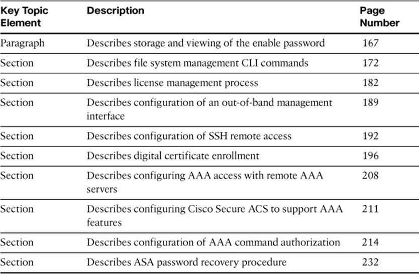
Command Reference to Check Your Memory
This section includes the most important configuration and EXEC commands covered in this chapter. It might not be necessary to memorize the complete syntax of every command, but you should be able to remember the basic keywords that are needed.
To test your memory of the commands, cover the right side of Tables 5-3 through 5-10 with a piece of paper, read the description on the left side, and then see how much of the command you can remember.
Table 5-3. Basic Device Settings Commands
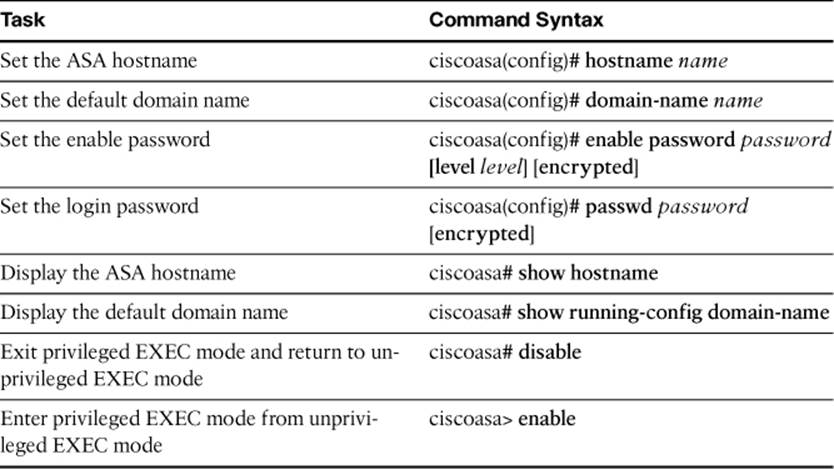
Table 5-4. Commands Related to Name-to-Address Mapping
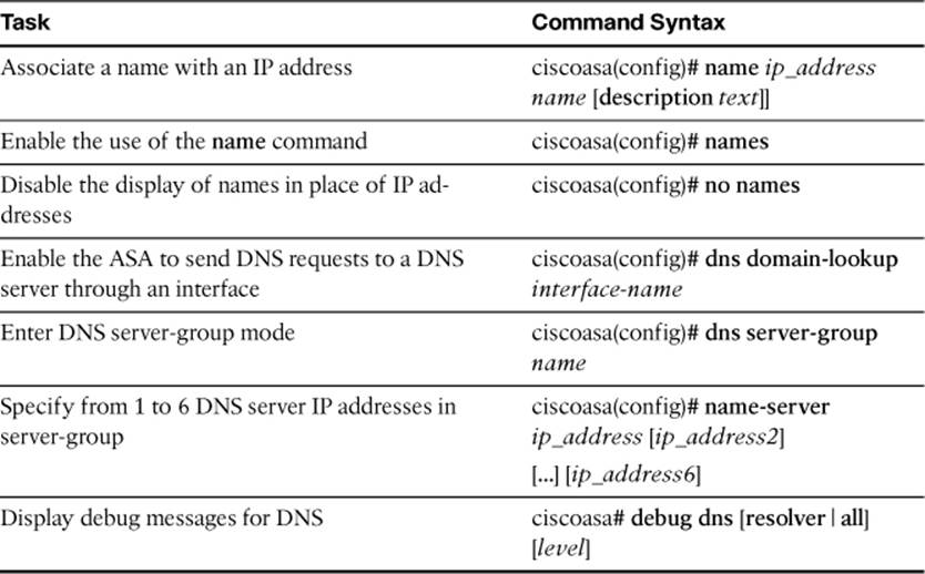
Table 5-5. File System Management Commands
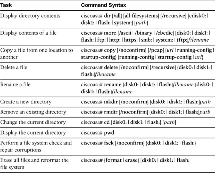
Table 5-6. Commands Related to Managing Software and Feature Activation
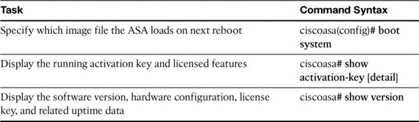
Table 5-7. Commands Related to Management Access
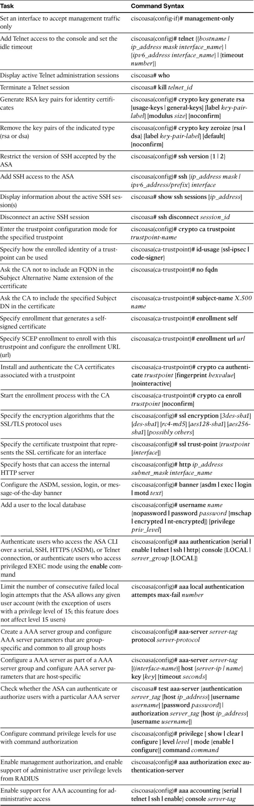
Table 5-8. SNMP Monitoring Commands
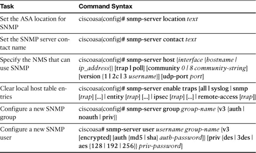
Table 5-9. Troubleshooting Commands
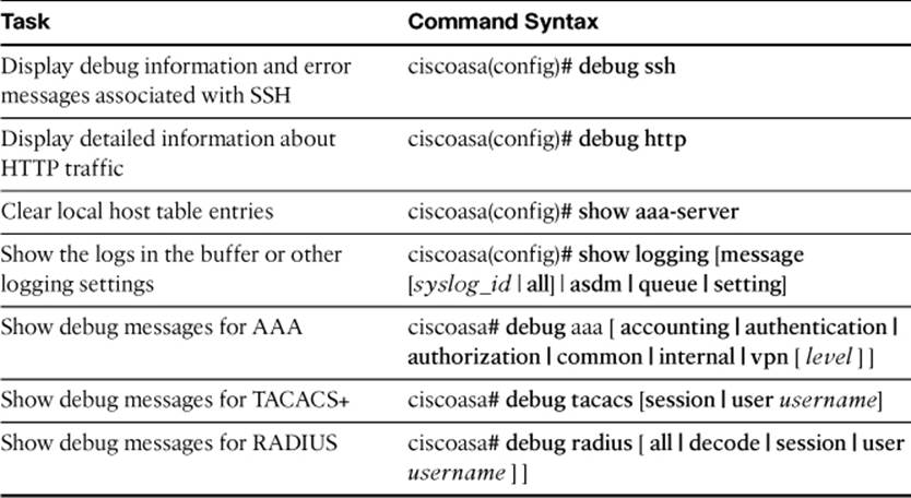
Table 5-10. Commands Related to Password Recovery
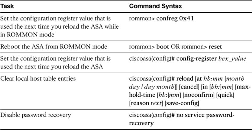
The FIREWALL exam focuses on practical, hands-on skills that are used by a networking professional. Therefore, you should be able to identify the commands needed to configure and test an ASA feature.
All materials on the site are licensed Creative Commons Attribution-Sharealike 3.0 Unported CC BY-SA 3.0 & GNU Free Documentation License (GFDL)
If you are the copyright holder of any material contained on our site and intend to remove it, please contact our site administrator for approval.
© 2016-2026 All site design rights belong to S.Y.A.