CCNP Security FIREWALL 642-618 Official Cert Guide (2012)
Chapter 7. Using Address Translation
This chapter covers the following topics:
• Understanding How NAT Works: This section describes the functionality of Network Address Translation (NAT), its benefits, and required information for implementing address translation on a Cisco ASA.
• Implementing NAT in ASA Software Versions 8.2 and Earlier: This major section covers the use of NAT in software versions 8.2 and earlier.
• Enforcing NAT: This section describes the difference between enabling NAT and requiring NAT on a Cisco ASA.
• Address Translation Deployment Options: This section describes the many various forms of address translation on a Cisco ASA, gives examples of NAT versus Port Address Translation (PAT), and describes which form of address translation is appropriate for various network scenarios, and in what situations NAT or PAT should not be used.
• Configuring NAT Control: This section demonstrates how to configure NAT control to require all transit traffic to be addressed by translation rules (and exemptions).
• Configuring Dynamic Inside NAT: This section demonstrates how to configure dynamic inside NAT, create global address pools, and alter the default system translation slot idle timer value.
• Configuring Dynamic Inside PAT: This section demonstrates how to configure dynamic inside PAT, allowing multiple internal hosts to share a single global IP address.
• Configuring Dynamic Inside Policy NAT: This section demonstrates how to configure dynamic inside policy NAT to create conditional translation rules based on the contents of access control lists.
• Verifying Dynamic Inside NAT and PAT: This section shows commands used to verify NAT and PAT configuration on an ASA using dynamic inside NAT or PAT.
• Configuring Static Inside NAT: This section demonstrates how to configure static inside NAT to create permanent mappings between internal hosts and global IP addresses.
• Configuring Network Static Inside NAT: This section demonstrates how to configure network static inside NAT, which allows for the creation of multiple static mappings with a single command.
• Configuring Static Inside PAT: This section demonstrates how to configure static inside PAT, which allows multiple servers, using unique ports, to share a single global IP address. Static inside PAT can also be used to perform port redirection for servers using custom ports (where the port the connection is directed to by the client, and the port the server is actually listening on, are different).
• Configuring Static Inside Policy NAT: This section demonstrates how to configure static inside policy NAT to create conditional translation rules based on the contents of access control lists, for servers requiring only outbound connectivity.
• Verifying Static Inside NAT and PAT: This section shows commands used to verify NAT and PAT configuration on an ASA using static inside NAT or PAT.
• Configuring No-Translation Rules: This section demonstrates how to configure dynamic and static identity NAT, or NAT bypass, for hosts that do not require translation.
• NAT Rule Priority: This section discusses the priority in which address translation rules are applied to traffic.
• Configuring Outside NAT: This section discusses and demonstrates how to configure outside NAT, for use when external hosts require translation when communicating with hosts on more secure interfaces.
• Other NAT Considerations: This section discusses effects of NAT on other elements of ASA configuration, and demonstrates how to configure DNS Rewrite.
• Troubleshooting Address Translation: This section discusses the steps in troubleshooting address translation issues.
• Implementing NAT in ASA Software Versions 8.3 and Later: This major section covers the use of NAT in software versions 8.3 and later.
• Major Differences in NAT Beginning in Software Version 8.3: This section provides a brief discussion of the major changes in how NAT is handled between current versions of the OS and older versions.
• NAT Table: This section discusses the structure of the NAT Table in OS versions 8.3 and higher and how the ASA determines which NAT rule to apply to individual packet flows.
• Configuring Auto (Object) NAT: This section demonstrates how to configure various NAT rule types for use with auto (object) NAT to include static address translations, static port mappings, dynamic NAT (one-to-one), and dynamic PAT (many-to-one).
• Verifying Auto (Object) NAT: This section shows the commands used to verify translation configuration and operation on an ASA using auto NAT.
• Configuring Manual NAT: This section discusses and demonstrates the configuration of manual NAT to include NAT exemptions and twice NAT.
• When Not to Use NAT: This section discusses times when the use of NAT is inappropriate with OS versions 8.3 and higher.
• Tuning NAT: This section discusses adjusting the translation slot global timer and activating DNS Rewrite.
• Troubleshooting NAT: This section discusses the common commands and consideration to troubleshoot problems with NAT when using OS versions 8.3 and higher.
The Cisco Adaptive Security Appliance (ASA) is frequently deployed at the border between a network using a private IP addressing scheme and the public Internet address space. To solve addressing issues when interconnecting these networks, the Cisco ASA supports Network Address Translation (NAT) and Port Address Translation (PAT).
This chapter discusses methods for configuring, verifying, and troubleshooting NAT and PAT deployed on a Cisco ASA.
The methods of performing address translation on a Cisco ASA were completely reworked beginning with OS version 8.3. Because the FIREWALL exam might include questions about address translation using both 8.2-and-before and 8.3-and-later versions of the OS, this chapter contains major sections for both 8.2-and-before and 8.3-and-later address translation. So this book serves as a valuable reference and provides, it provides full coverage for both methods; however, the exam will likely emphasize the methods used in OS versions 8.3 and later, so pay particularly close attention when studying that portion of this chapter.
“Do I Know This Already?” Quiz
The “Do I Know This Already?” quiz allows you to assess whether you should read this entire chapter thoroughly or jump to the “Exam Preparation Tasks” section. If you are in doubt about your answers to these questions or your own assessment of your knowledge of the topics, read the entire chapter. Table 7-1 lists the major headings in this chapter and their corresponding “Do I Know This Already?” quiz sections. You can find the answers in Appendix A, “Answers to the ‘Do I Know This Already?’ Quizzes.”
Table 7-1. “Do I Know This Already?” Section-to-Question Mapping
Caution
The goal of self-assessment is to gauge your mastery of the topics in this chapter. If you do not know the answer to a question or are only partially sure of the answer, you should mark that question as wrong for purposes of the self-assessment. Giving yourself credit for an answer you correctly guess skews your self-assessment results and might provide you with a false sense of security.
1. Which of the following is not a benefit of NAT?
a. Hides internal addressing and topology from hosts on the Internet.
b. Allows multiple hosts to share the same globally unique IP address.
c. Mitigates global address depletion.
d. Allows change of ISP without internal re-addressing.
e. All of the above are benefits of NAT.
2. Which of the following is true when NAT control is enabled on an ASA running an OS version before 8.2?
a. Translation rules are not required but will be performed if configured.
b. Configuration of translation rules is not permitted.
c. Translation rules are required for all transit traffic.
d. Translation rules are required only for sessions initiated on a higher security interface bound for a lower security interface.
3. Your ASA is running OS version 8.2 and is configured for dynamic inside PAT. Hosts on the 10.0.0.0/24 internal network share global IP address 209.165.200.254. As hosts initiate TCP connections to external servers, what happens?
a. The source IP address is translated to 209.165.200.254. The source port is retained, unless that port is already in use, in which case it is translated.
b. The source IP address is translated to 209.165.200.254. If the original source port is 1024 or greater, it is translated to a seemingly random port number in the range 1024–65535.
c. The source IP address is translated to 209.165.200.254. Each host is then allocated ten port numbers for its use. These ports are assigned to subsequent connections from the source host and return to availability as sessions are terminated.
d. The described configuration is invalid.
4. An application embeds IP addresses at the application layer and uses end-to-end encryption. Which “flavor” of address translation should be used in this situation on an ASA running OS version 8.2?
a. Dynamic inside NAT
b. Static inside policy NAT
c. Dynamic inside policy NAT
d. Static outside NAT
e. NAT bypass
5. Which of the following commands changes the translation slot idle timer value to 1 hour?
a. translation idle timer 01:00:00
b. xlate idle timer 01:00:00
c. timeout xlate 01:00:00
d. timer xlate 01:00:00
e. None of these answers are correct.
6. An ASA is running OS version 8.2. Given the following partial ASA configuration, with all translation slots cleared, to which address will host 10.0.0.101 be translated when initiating a session to web server 172.16.0.5 on the DMZ network?
access-list NO_NAT permit ip host 10.0.0.101 172.16.0.32 255.255.255.224
nat-control
nat (inside) 5 access-list NO_NAT
nat (inside) 1 10.0.0.0 255.255.255.0 tcp 0 0 udp 0
nat (inside) 2 0.0.0.0 0.0.0.0 tcp 0 0 udp 0
global (outside) 1 209.165.200.235-209.165.200.254 netmask 255.255.255.224
global (DMZ) 2 172.16.0.101-172.16.0.254 netmask 255.255.255.0
global (DMZ) 5 interface
a. 209.165.200.235
b. 172.16.0.101
c. 172.16.0.1 (the ASA DMZ interface IP)
d. None of these answers are correct because the translation attempt will fail.
7. Your ASA is running OS version 8.2. You are tasked to configure dynamic inside PAT for hosts on the inside network when they communicate with the DMZ network. The DMZ network is 172.16.0.0/24. The PAT address will be 172.16.0.254. Which subnet mask should you enter in the NAT Rules configuration window?
a. 255.255.255.0
b. 255.255.255.255
c. 0.0.0.255
d. 0.0.0.0
e. None of the answers are correct. There is no subnet mask field in the NAT Rules configuration window.
8. Your ASA is running OS version 8.2. You are tasked to configure dynamic inside PAT for hosts on the inside interface when communicating with external hosts (through the outside interface). Because of a lack of IP addresses, you will use the IP address of the ASA’s outside interface, 209.165.200.226, as the PAT address. Which of the following configurations is correct?
a. nat (inside) 5 0.0.0.0 0.0.0.0
global (outside) 5 209.165.200.226
b. nat (inside) 1 10.0.0.0 255.255.255.0
global (outside) 1 209.165.200.226
c. nat (inside) 0 10.0.0.0 255.255.255.0
global (outside) 0 interface
d. nat (inside) 300 10.0.0.0 255.255.255.0
global (outside) 300 interface
e. None of the answers provide a valid configuration.
9. Your ASA is running OS version 8.2. You have a web server on the DMZ network, address 172.16.0.5. You are tasked with granting access to this server to all Internet-based hosts, using global address 209.165.200.228. Which of the following shows the correct command or commands to accomplish this, assuming access lists are already configured to permit this traffic?
a. Your ASA is running OS versionnat (DMZ) 4 172.16.0.5 255.255.255.255
global (outside) 4 209.165.200.228 netmask 255.255.255.255
b. Your ASA is running OS versionstatic (DMZ,outside) 172.16.0.5 209.165.200.228 netmask 255.255.255.255
c. Your ASA is running OS versionaccess-list WEB permit tcp any host 209.165.200.228 eq www
static (DMZ,outside) access-list WEB
d. Your ASA is running OS versionstatic (DMZ,outside) 209.165.200.228 172.16.0.5 netmask 255.255.255.255
10. Your ASA is running OS version 8.2. You have an SMTP email server on the DMZ, address 172.16.0.20. This host must be reachable from the Internet using port 25, and from the PartnerNet (172.18.10.0/24) using port 2525. Additionally, a web server on the DMZ, address 172.16.0.5, shares the global IP address 209.165.200.235 with the email server, for the outside interface. Which of the following configurations would work?
a. static (DMZ,outside) tcp 209.165.200.235 25 172.16.0.20 25
static (DMZ,outside) tcp 209.165.200.235 80 172.16.0.5 80
static (DMZ,PartnerNet) tcp 172.18.10.20 2525 172.16.0.20 25
b. static (DMZ,outside) 209.165.200.235 25 172.16.0.20 25
static (DMZ,outside) 209.165.200.235 80 172.16.0.5 80
static (DMZ,PartnerNet) 172.18.10.20 2525 172.16.0.20 25
c. static (DMZ,outside) tcp 172.16.0.20 25 209.165.200.235 25
static (DMZ,outside) tcp 172.16.0.5 80 209.165.200.235 80
static (DMZ,PartnerNet) tcp 172.16.0.20 25 172.18.10.20 2525
d. static (DMZ,outside) tcp 209.165.200.235 2525 172.16.0.20 25
static (DMZ,outside) tcp 209.165.200.235 80 172.16.0.5 80
static (DMZ,PartnetNet) tcp 172.18.10.20 25 172.16.0.20 25
11. An ASA is running OS version 8.2. When using static inside policy NAT, hosts on less secure interfaces are able to initiate communication with hosts on more secure interfaces that are subject to translation. True or false?
a. True
b. False
12. Your ASA is running OS version 8.2. Your inside network is 10.0.0.0/24. Your DMZ network is 172.16.0.0/24. You want to configure hosts on the inside network to reach the DMZ without being translated, while still maintaining the ability to communicate with the Internet through use of address translation. Which of the following configuration samples accomplishes this?
a. access-list NO_NAT permit ip 10.0.0.0 255.255.255.0 172.16.0.0 255.255.255.0
nat (inside) 1 access-list NO_NAT
nat (inside) 1 10.0.0.0 255.255.255.0
global (outside) 1 209.165.200.235-209.165.200.254 netmask 255.255.255.224
b. access-list NO_NAT permit ip 10.0.0.0/24 172.16.0.0/24
nat (inside) 1 10.0.0.0/24
nat (inside) 0 access-list NO_NAT
global (outside) 1 209.165.200.235-209.165.200.254/27
c. access-list NO_NAT permit ip 10.0.0.0 255.255.255.0 172.16.0.0 255.255.255.0
nat (inside) 1 10.0.0.0 255.255.255.0
nat (inside) 0 access-list NO_NAT
global (outside) 1 209.165.200.235-209.165.200.254 netmask 255.255.255.224
d. access-list NO_NAT permit ip 10.0.0.0 255.255.0.0 172.16.0.0 255.255.255.0
nat (inside) 1 10.0.0.0 255.255.255.0
nat (inside) 0 access-list NO_NAT
global (outside) 1 209.165.200.235-209.165.200.254 netmask 255.255.255.224
13. Your ASA is running OS version 8.2. Hosts on the inside network need to reach a web server on the DMZ. However, they use an Internet-based DNS server for name resolution. How would you configure the ASA to ensure that these connections are successful?
a. static (DMZ,outside) 209.165.200.228 172.16.0.5 dns
b. nat (inside) 1 10.0.0.0 255.255.255.0 dns
global (outside) 1 interface
c. static (DMZ,inside) 172.16.0.5 172.16.0.5 dns
d. None of the answers are correct.
14. An ASA is running OS version 8.3. Where in the configuration would you create an auto NAT rule?
a. In global configuration mode
b. As part of the NAT Table configuration
c. In network object group configuration mode
d. In NAT configuration mode
e. In network object configuration mode
15. An ASA is running OS version 8.3. Which of the following is the correct order for determining which NAT rule to apply to a packet?
a. Manual NAT, auto NAT, twice NAT, manual NAT after auto NAT
b. Static inside NAT, dynamic inside policy NAT, dynamic inside NAT
c. Manual NAT, auto NAT, manual NAT after auto NAT
d. NAT 0 with access list, static inside NAT, static inside policy NAT, auto NAT
e. NAT exemption, manual NAT, auto NAT, dynamic inside NAT
16. An ASA is running OS version 8.3. How many auto NAT rules can the NAT Table contain for a single network object?
a. One
b. Two
c. Three
d. Limited only by memory
17. An ASA is running OS version 8.3. You are using ASDM to add a new network object. What four values are available settings in the Type field?
a. host
b. pool
c. range
d. subnet
e. FQDN
f. network
18. An ASA is running OS version 8.3. All translation slots are cleared. The host 10.0.0.101 initiates a connection using source port 49151 to the DMZ web server, 172.16.0.5. What are the values in the source address and source port fields when this packet is forwarded onto the DMZ segment?
object network INSIDE-SEGMENT
subnet 10.0.0.0 255.255.255.0
object network IT-SEGMENT
subnet 10.0.1.0 255.255.255.0
object network OUTSIDE-NAT-POOL
range 209.165.200.235 209.165.200.254
object network INSIDE-SEGMENT
nat (any,outside) dynamic OUTSIDE-NAT-POOL interface
object network IT-SEGMENT
nat (any,DMZ) dynamic 172.16.0.254
a. 172.16.0.254/49151
b. 209.165.200.235/A seemingly random port, 1024 or higher, based on an internal ASA algorithm
c. 10.0.0.101/1024
d. 172.16.0.254/A seemingly random port, 1024 or higher, based on an internal ASA algorithm
e. 10.0.0.101/49151
f. 10.0.0.101/A seemingly random port, 1024 or higher, based on an internal ASA algorithm
19. An ASA is running OS version 8.3. Given the following configuration, on what port is the DMZ HTTPS server actually listening for incoming connections?
object network DMZ-HTTPS-PRIV
nat (DMZ,outside) static DMZ-PAT-OUTSIDE service tcp 8443 443
a. 8443
b. 443
c. Neither 8443 nor 443
d. There is not enough information in the sample configuration to make a determination.
20. An ASA is running OS version 8.3. In what ASDM window would you define source and destination interface settings when creating an auto NAT rule?
a. Add Network Object
b. Add NAT Rule
c. Advanced NAT Settings
d. Network Object NAT Settings
21. You see the following in the output of the show xlate command:
TCP PAT from DMZ:172.16.0.15 8443-8443 to outside:209.165.200.230 443-443
flags sr idle 0:25:53 timeout 0:00:00
What is the meaning of the s and r flags?
a. r means sequence number randomization is enabled, and s means static NAT is being used.
b. r means port mapping is being used, and s means static NAT is being used.
c. r means sequence number randomization is enabled, and s means SYN flood protection is enabled.
d. r means port mapping is being used, and s means SYN flood protection is enabled.
22. An ASA is running OS version 8.3. What is the effect of the following manual NAT rule?
nat (inside,outside) 1 source dynamic INSIDE-SEGMENT VENDOR-SERVER-PAT
destination static VENDOR-SERVER VENDOR-SERVER service HTTPS
VENDOR-PORTMAP
a. Hosts in the INSIDE_SEGMENT object will have their addresses translated to VENDOR-SERVER-PAT only when connecting to the VENDOR-SERVER address using the port 443.
b. Hosts in the INSIDE_SEGMENT object will have their addresses translated to VENDOR-SERVER-PAT only when connecting to the VENDOR-SERVER address using the port defined in the service object named VENDOR-PORTMAP.
c. Hosts in the INSIDE_SEGMENT object will have their addresses translated to VENDOR-SERVER-PAT only when connecting to the VENDOR-SERVER address using the port defined in the service object named HTTPS.
d. None of these answers are correct.
Foundation Topics
This chapter describes how IP addresses can be altered or translated as packets move through an ASA. The various types of Network Address Translation (NAT) and Port Address Translation (PAT) are covered.
NAT performs the translation of source and/or destination IP addresses in packets traversing the ASA. PAT, in addition to translating IP addresses, translates source port numbers in TCP or UDP packets, thus allowing many-to-one translation of source IP addresses. This allows numerous internal hosts to share a single public IP address when communicating with external networks.
The methods of performing address translation on a Cisco ASA were completely reworked beginning with OS version 8.3. Because the FIREWALL exam includes questions about address translation using both pre- and post-8.3 versions of the OS, this chapter contains major sections for both pre- and post-8.3 address translation.
Understanding How NAT Works
Network Address Translation (NAT) was developed to overcome IP addressing problems that occurred when the ARPANet, which interconnected only a few dozen large institutions, became the Internet, which had the ability to interconnect networks and computers globally, leading to massive growth. There simply were not enough addresses available in the originally designed IP addressing scheme to accommodate universal connectivity, especially given the manner in which addresses were originally assigned. Therefore, a system of “private” IP addresses was developed, first in RFC 1597, which was then superseded by the better-known RFC 1918, which allows multiple networks around the world to deploy the exact same IP addresses for addresses that require only local uniqueness. This eliminates the need to maintain globally unique addresses for every connected host worldwide.
Because private IP addresses are intended for local use only and are considered “nonroutable” on the public Internet, NAT is required to translate these private (local) IP addresses to public (global), routable addresses when hosts on a private network need to communicate with hosts outside of that private network.
Additionally, because many organizations can deploy the same private IP addresses, due to local significance, NAT is required if hosts on these networks with overlapping addresses need to communicate with each other.
NAT thus provides the following benefits:

• NAT mitigates public IP address depletion because, when used in combination with PAT, many private hosts can share a single public IP address, while using unique private addresses internally.
• NAT allows an organization to undergo a change of Internet service provider (ISP), with provider-dependent public IP addresses, without having to change its internal, private addressing plan.
• As a security measure, NAT hides the internal IP addressing scheme and network topology from the public Internet, even while it allows interconnectivity.
In its simplest form, for an ASA to perform NAT or PAT, four pieces of information are required:
• Original source IP address (and port) in the packet
• Interface where the original packet enters the ASA (ingress interface)
• Interface where the packet will exit the ASA (egress interface)
• Translated address (and, optionally, port) to insert into the packet
Understanding this concept is important because these four pieces of information are required in each of the many variations of NAT and PAT. If any of these four items is unknown, an ASA cannot perform address translation. Also, these items are all recorded in the translation table (xlate table) maintained by the ASA for tracking address translation that it is performing.
Beginning in OS version 8.3, NAT is organized in an object-oriented manner, rather than being interface-dependent. Although it is still technically necessary to include both ingress and egress interfaces in NAT rules, there is an option to use “any” as the ingress or egress interface definition, so translation rules are not necessarily applied between only a single pair of interfaces. Furthermore, it is possible, with a single rule, to translate both source and/or destination addresses in a packet, so NAT is no longer limited to source address only. Finally, NAT rules are no longer determined in an interface-sorted manner, according to a priority scheme, but rather in a NAT table that is not sorted by interface. All these items are covered in the section, “Implementing NAT in ASA Software Versions 8.3 and Later.”
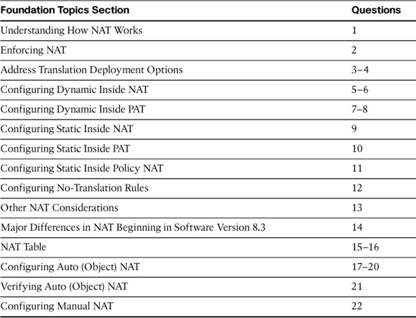
Figure 7-1 shows a basic example of NAT implementation. An internal host, with private IP address 10.0.0.101, needs to communicate with a web server on the Internet.
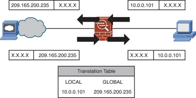
Figure 7-1. Basic Address Translation Example
When the NAT-enabled Cisco ASA in Figure 7-1 receives a packet from the internal host, it translates the source IP address of the packet before forwarding the packet to the Internet. This is necessary because the private IP address assigned to the host is not allowed to be routed through the Internet. In the figure, the host’s address is translated to the public IP address 209.165.200.235. When a host on the Internet receives this packet, it sends its reply to 209.165.200.235 as the destination IP address. This packet arrives at the Cisco ASA, which consults its address translation table and, finding the entry related to the translation being performed, translates this destination IP address back to 10.0.0.101 before forwarding it onto the internal network to the originating host.
So, in the example shown in Figure 7-1, the four required pieces of information are
• 10.0.0.101: Original source IP address
• inside: Ingress interface
• outside: Egress interface (determined by routing decision)
• 209.165.200.235: Translated source IP address
Implementing NAT in ASA Software Versions 8.2 and Earlier
Beginning with software version 8.3, Cisco radically altered the manner in which address translation is configured on an ASA. To understand how this new method of configuring address translation differs from earlier versions, and the benefits it brings, it is important to understand how NAT worked before these changes. Also, the FIREWALL exam expects you to be familiar with both methodologies, and possibly expects you to be able to compare different configurations that actually achieve the same result—one using “legacy” syntax and another using current syntax.
Enforcing NAT
The basic example of NAT just detailed stated that a “NAT-enabled” ASA received packets. So, what makes an ASA NAT-enabled? Simply put, any ASA that is configured to perform NAT is NAT-enabled. However, if an organization uses RFC 1918 private addresses, NAT is required to permit communication with external networks. You must therefore be able to distinguish between performing NAT and enforcing NAT. As already stated, any ASA configured to perform NAT will do so. What, then, does it mean to configure an ASA to enforce NAT?
Prior to OS version 7.0, there was no way for a PIX firewall to forward packets from a higher-security interface to a lower-security interface (“outbound” traffic) without being configured with rules for address translation. Thus, it was a requirement of passing traffic that all outbound packets be matched to a translation rule (even if such a rule were to exempt a packet from translation). The use of NAT was thus enforced, not merely permitted. Starting with OS version 7.0, and the introduction of the Cisco ASA, an ASA does not enforce the use of NAT, by default.
It is important to note that if an organization’s network already contains enough globally unique IP addresses to accommodate all internal hosts, NAT is not necessary to permit that network to intercommunicate with the rest of the world. The internal hosts could be configured with globally unique addresses, and the ASA could simply forward traffic without any address translation. However, even in such a case, some organizations choose to assign private, RFC 1918 addresses to their internal network, especially if their IP addresses were allocated to them by an ISP rather than registered to them directly. If such an organization decides to change ISPs, it does not need to re-address its entire internal network, which it would otherwise have to do if it had allocated the globally unique IPs directly to internal hosts. It is important to remember the security implications of NAT (hiding internal address and topology information) before making such a decision.
Even if an organization used private IP addresses, it would not be necessary to perform NAT on the ASA. The ASA would simply forward packets with the original addresses intact. The assumption would be that another inline device would perform NAT. Otherwise, the packets would be dropped as nonroutable traffic when they entered the Internet space.
With OS versions 7 and later, it is still possible to enforce the use of NAT. Essentially, the ASA functions much as a pre-OS version 7 firewall would, and drops any outbound packets not addressed by configured translation rules. Enforcing NAT is considered a security enhancement, as it can create another layer of access control (dropping packets that have no translation rule), and is thus widely used, even at the cost of increased configuration complexity.
The function used to enforce NAT is known as NAT control, and its configuration is covered later in this chapter alongside the configuration of NAT rules.
Address Translation Deployment Options
As previously mentioned, there are many variations of address translation that can be performed by a Cisco ASA. One of the deployment options, just covered, is whether to enforce the use of NAT as a security enhancement.
If you are using NAT, there are many further options to consider, such as whether to perform fixed or temporary address translation. Fixed translation, where an original address is permanently assigned the translated IP address, is known as static NAT. Temporary translation, where an original host is assigned an address from an available pool, and that address is returned to the pool after a configurable idle time, is known as dynamic NAT. Static NAT is typically used with servers, and dynamic NAT is typically used with client hosts.
There are two “directions” for NAT usage, known as inside NAT and outside NAT. If the packets arriving at the ASA from a host subject to translation ingress an interface with a higher security level than the interface they egress, the address translation performed is known as inside NAT. Conversely, if packets arriving from a host subject to translation ingress an interface with a lower security level than the interface they egress, the address translation performed is known as outside NAT. Recall that the assigned security level of an interface determines whether that interface, and networks reachable through that interface, is considered more or less secure relative to the other interface involved in a traffic flow.
Note
It is always important to remember which host is subject to translation. For instance, packets originating on the Internet and destined for an internal web server do not constitute the use of outside NAT. It is not the originating host that is subject to address translation, but rather the internal web server. Thus, packets from the host subject to translation (the internal web server) ingress the ASA on an interface that has a higher security level than the interface they egress, and the translation performed is inside NAT.
The implementation of NAT or PAT can be further enhanced by making it conditional (based on a policy). Generally, the need for this arises based on access restrictions at the destination host, but there are many reasons it may be necessary in practice. Such implementation is accomplished by using an access control list (ACL) to define the policy. Traffic flows defined as permitted in the ACL become those subject to the policy NAT implementation.
Thus, when performing NAT, you have the choices of dynamic inside NAT, static inside NAT, dynamic outside NAT, and static outside NAT. Each of these deployment options can further be subdivided into policy versus nonpolicy options.
A final option to consider is to exempt certain traffic from NAT. If NAT control is not enabled (NAT is not being enforced), this is unnecessary. However, if NAT control is enabled, and there are traffic flows that you do not want to undergo address translation, you must configure NAT exemption rules.
NAT Versus PAT
It is important to understand the difference in implementation between NAT and PAT so that you understand when each choice is appropriate for your particular network environment.
When you use inside NAT, only the source IP address of the internal host is translated, and a one-to-one mapping is made between the original (local) IP address and the translated (global) address assigned to the host. The global address can be assigned in either a static (fixed and permanent) or dynamic (from a pool and temporary) manner. If there are not enough global IP addresses to support all internal hosts, some hosts will not be able to communicate through the ASA.
Figure 7-2 illustrates the use of NAT with an example of inside NAT. Recall that inside NAT means that traffic from the host subject to translation ingresses the ASA on a more secure interface than it egresses the ASA. In the figure, two hosts connected to the inside interface of the ASA both need to communicate with destinations on the Internet.
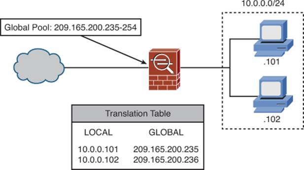
Figure 7-2. Dynamic Inside NAT Scenario
In Figure 7-2, hosts on the internal 10.0.0.0/24 network share a pool of global addresses, 209.165.200.235-254, from which addresses are dynamically allocated to hosts as they make connections, and to which addresses are returned after an idle period. Host 10.0.0.101 is assigned the first address from the pool, 209.165.200.235, when it makes the first outbound connection. Host 10.0.0.102, upon making its connection, is assigned the next address from the pool, 209.165.200.236. This is merely an example, although it also illustrates how the ASA allocated pool addresses prior to OS version 8.0(3). As of version 8.0(3), a seemingly random address is allocated from the pool based on an internal ASA algorithm.
Note
The example deliberately uses a pool that is not congruent with the boundaries of subnetting, such as 209.165.200.240/28 would be. Although the command that creates a global pool optionally uses a subnet mask parameter, it does not perform subnetting of the network attached to the ASA. This is an important concept for you to understand to maximize the efficiency of address allocation within your own network environment.
Figure 7-3 illustrates the use of NAT with an example of inside PAT. When you use inside NAT, only the source IP address of the internal host is translated, and a one-to-one mapping is made between the original (local) IP address and the translated (global) address assigned to the host. With PAT, however, both the source IP address and source port (for TCP and UDP packets) are translated, which creates a many-to-one mapping, with multiple internal hosts sharing a single global IP address, and each of their TCP or UDP connections being assigned a unique port number, tracked by the ASA for the duration of the connection. This allows for maximum efficiency in conserving global IP addresses, but is not compatible with all applications.
Figure 7-3. Dynamic Inside PAT Scenario
In Figure 7-3, hosts on the internal 10.0.0.0/24 network share a single global address, 209.165.200.254. When host 10.0.0.101 initiates a TCP connection to a web server on the Internet, it is assigned the 209.165.200.254 address, and its original TCP source port of 49501 is translated to port 46224. When host 10.0.0.102 makes its connection to the same web server, it also uses global IP address 209.165.200.254, and is assigned the translated port 27645. Subsequent connections from any host on the 10.0.0.0/24 network (including .101 and .102) are assigned seemingly random source port numbers, based on an internal ASA algorithm.
Input Parameters
With these considerations in mind, we can now more fully define the overall input parameters that you will need to consider in determining how NAT or PAT functionality needs to be defined for your particular environment.
Table 7-2 lists and describes input parameters. You must understand and fully enumerate these parameters to correctly deploy address translation rules for your environment.
Table 7-2. Address Translation Input Parameters
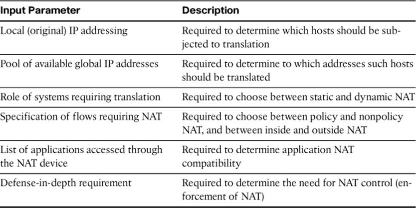
It is important to remember that the terms “local” and “global,” when related to NAT configuration on a Cisco ASA, really equate to “original” and “translated,” respectively, because in the case of outside NAT, the local address is frequently that of a foreign network, and the global addresses to which the local addresses are translated are usually from an internal network.
Regarding system roles, each system can generally be defined as either a client (a system that only initiates connections) or a server (a system that accepts incoming connections, and can also initiate outgoing connections). Client hosts can generally operate successfully through dynamic NAT, but servers require static NAT, as the IP addresses to which their clients need to connect must be predictable and fixed.
It is important to know if your organization uses applications that do not work with NAT or PAT. Examples of such applications are presented later, in the section, “NAT Exemption.”
Deployment Choices
The decision of whether to use inside or outside NAT, policy or nonpolicy NAT, or static or dynamic NAT may at first seem complex. Table 7-3 presents the various deployment choices, along with the criteria that normally make such a choice appropriate.
Table 7-3. NAT Deployment Choices and Criteria
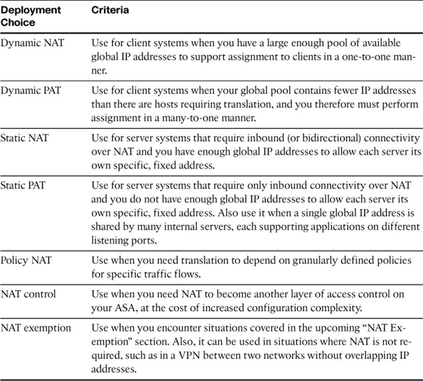
On a single Cisco ASA, it is possible to deploy a combination of all the options in Table 7-3, depending on your needs.
When NAT is combined with access controls, on a Cisco ASA running an OS version prior to 8.3, NAT configuration necessarily influences the configuration of interface ACLs, AAA rules, and Modular Policy Framework (MPF) rules (each topic is covered in other chapters).
NAT Exemption
The last deployment choice for NAT is when not to use it. Remember, of course, that if NAT control is not enabled, then all traffic is exempted from NAT. That is, if NAT rules are configured, they are implemented, but traffic that is not subject to such rules is forwarded without the requirement for NAT (NAT is not enforced).
The following is a list of situations that would require you to exempt certain traffic from NAT on an ASA that otherwise enforces NAT:
• Do not use NAT or PAT with applications that embed IP addresses on the application layer and use end-to-end encryption. With encrypted traffic, the Cisco ASA cannot translate embedded addresses and allow such applications to work properly across NAT.
• Do not use NAT or PAT with applications that authenticate entire packets (such as IPsec Authentication Header [AH] or Border Gateway Protocol [BGP]). When a packet hash value is calculated, and then addresses and/or port numbers are translated later, the verification of the hash at the other end of the communication will fail, and the packet will be dropped.
• Do not use NAT or PAT with applications that establish additional dynamic sessions, and for which the ASA does not support protocol-specific inspection rules. Also, if the application uses an encrypted control channel, the ASA will not be able to inspect the packet contents and perform modifications allowing the application to work properly across NAT/PAT.
There are other situations in which you will typically choose to exempt traffic from NAT/PAT, but in such cases, it is a choice, whereas the list just presented shows when it is a requirement. The most frequent examples of this are traffic that will traverse a VPN connection (for more information on VPNs, consult the CCNP Security VPN Official Certification Guide), or traffic between two internal networks, such as from the inside network to the DMZ network. Although such traffic traverses the ASA, the private addresses in use are never seen in an external environment where they would be considered nonroutable, so address translation is not necessary.
Configuring NAT Control
As previously mentioned, NAT control is a feature that configures the ASA to enforce NAT usage—that is, to require a translation rule for each host on a more secure interface when it communicates with hosts on lower security interfaces. (NAT exemption is an acceptable translation rule.) NAT control is disabled by default.
When NAT control is enabled and a host on a more secure interface attempts communication through the ASA to a less secure interface, the ASA first checks to see if there is an existing entry in the translation table for the host in question. Such an entry would exist if the host had previously communicated through the ASA, there was a configured translation rule for the host, and a translation slot had been created for that host and had not yet expired due to the xlate timeout value being exceeded. If an entry exists, the ASA performs the same translation for the host as previously.
If there is not an existing entry, one will be created if a translation rule is configured for the host. If there is not an existing entry, and no translation rule exists to create one, the traffic is dropped.
Note
NAT is not required between same security level interfaces even if NAT control is enabled (as long as the ASA is configured to permit traffic between same security level interfaces). You can configure NAT if desired, and the ASA will perform address translation for the traffic passing between the same security level interfaces.
Figure 7-4 demonstrates how to enable NAT control (navigate to Configuration > Firewall > NAT Rules). NAT control is a global feature and is either on or off for the entire ASA, not specific interfaces or translation rules. However, it is configured in the NAT Rules window of the device configuration.
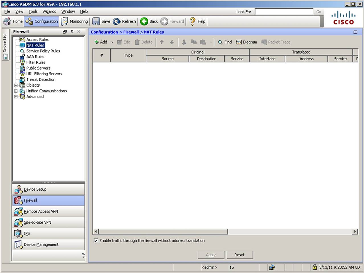
Figure 7-4. Enabling NAT Control
Note
All figures in the 8.2 and earlier NAT configuration examples use ASA OS version 8.23 with ASDM version 6.3. All figures in the 8.3 and later NAT configuration examples use ASA OS version 8.42 with ASDM version 6.45. Therefore, you might notice differences in some appearance and options.
At the bottom of the NAT Rules window is a check box that is checked by default. To enable NAT control, uncheck the Enable Traffic Through the Firewall Without Address Translation check box and click Apply.
The CLI command generated by the change made is as follows:
nat-control
If you are configuring the ASA from the CLI, you can enter this command directly in global configuration mode.
Configuring Dynamic Inside NAT
Dynamic inside NAT creates a temporary translation entry (slot) in the translation table when a host on a more secure interface sends traffic through the ASA to a less secure interface. Each local (original) address configured to use NAT on the ingress interface is translated to a global (translated) address selected from a configured pool on the egress interface. The translation is kept in place until a configurable idle timer expires (3 hours by default) or the translation slot is manually cleared by an administrator. Because these translations are dynamic, the same host, initiating connections at different times, is frequently translated to different global addresses.
Dynamic inside NAT should generally be used for client hosts that need outbound connectivity only. This is because, when using dynamic inside NAT, hosts on less secure interfaces cannot initiate connections to hosts on more secure interfaces that are configured to use dynamic NAT translation, unless the translation slot has already been created by outbound packets, and the interface access list on the less secure interface permits such a connection (interface access lists are discussed in Chapter 8, “Controlling Access Through the ASA”). Additionally, as previously mentioned, servers must have addresses that are fixed and predictable in order for their clients to connect to them successfully, so dynamic NAT is not an option for service-providing hosts.
Recall the four pieces of information necessary for an ASA to perform NAT:
• Original source IP address (and port) in the packet
• Interface where the original packet enters the ASA (ingress interface)
• Interface where the packet will exit the ASA (egress interface)
• Translated address (and, optionally, port) to insert into the packet
To configure an ASA to perform dynamic inside NAT, you must specify these four pieces of information. Also, you can optionally alter the default global translation slot idle timeout value (known as the xlate timer).
In demonstrating how to configure dynamic inside NAT, we will use the example introduced earlier. Figure 7-5 shows the scenario. Hosts on the 10.0.0.0/24 network, which is connected to the ASA inside interface, will share a pool of global addresses, 209.165.200.235-254, configured on the ASA outside interface. Additionally, this example will assume that the xlate timeout value needs to be adjusted from 3 hours to 1 hour.
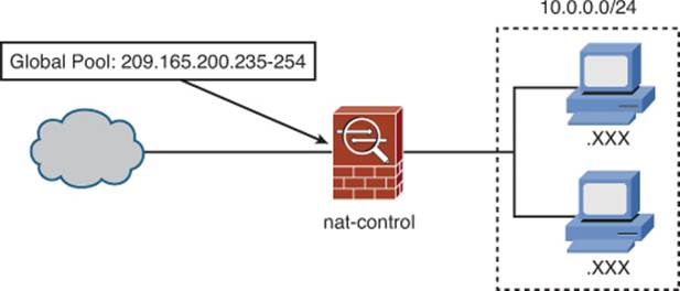
Figure 7-5. Dynamic Inside NAT Scenario
The configuration scenario assumes that routing between all involved networks has been properly configured, and that any access lists present on the ASA permit communication between the inside network and the Internet.
To configure the scenario in Figure 7-5, first navigate to Configuration > Firewall > NAT Rules. Click Add to open a drop-down menu, and choose Add Dynamic NAT Rule. Figure 7-6 shows the resulting Add Dynamic NAT Rule dialog box, in which you configure the specifics of the new NAT rule.
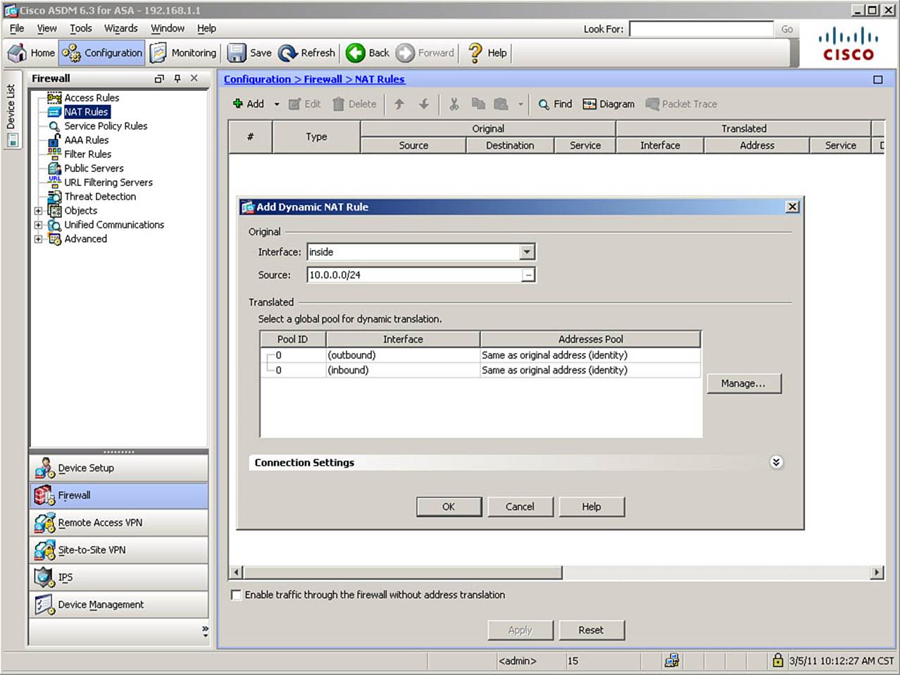
Figure 7-6. Adding a Dynamic NAT Rule
From the Interface drop-down list, select the ingress interface for this NAT rule. In Figure 7-6, the inside interface is selected. Next, in the Source field, enter the local IP address or address range that will be subject to this NAT rule. Optionally, click the ellipsis (...) button to choose an IP address or range that has already been defined within Cisco ASDM. If entered manually, define the address and subnet mask using prefix and length notation. Figure 7-6 shows the 10.0.0.0/24 address range being specified.
Note
If you enter an IP address with no mask, Cisco ASDM treats it as a host address, even if it ends with a 0 in the final octet.
Note
Although it is possible to define a source range of 0.0.0.0/0 (any IP address), this is poor security practice, as it would perform NAT translation for any source IP, whether or not that IP was a valid address in the range reachable through the ingress interface. This would only be overcome if you enable reverse-path verification with the ip verify reverse-path interface intf_name command.
Finally, in the Translated area of the dialog box, any previously defined global pools are listed. You can select one to which you want to bind this NAT rule, and click OK. Because, in this example, only the system default NAT exemption rules are currently known, click the Manage button to begin the configuration of a new global pool. This will open the Manage Global Pool dialog box.
The Manage Global Pool dialog box allows you to select or edit a global address pool that has already been defined, or create a new global address pool. To create a new global pool, click the Add button, which opens the Add Global Address Pool dialog box, shown in Figure 7-7. This dialog box allows you to create address translation pools and bind them to ASA interfaces.
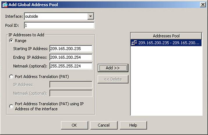
Figure 7-7. Creating a Global Address Pool
When you create a global pool, you must bind it to a particular ASA interface. This is because the same originating hosts that are subject to a NAT rule might, at any given time, be in communication with hosts reachable through different lower security interfaces. Recall that all translation rules require an original address, an ingress interface, a translated address, and an egress interface in order to completely define an address translation rule. You have already completed the definition of the first two factors—the creation of the global address pool defines the latter two.
To select an interface where the global pool will be used, from the Interface drop-down list, select the interface where traffic using this pool will egress the ASA. In Figure 7-7, the outside interface is selected.
Next, enter a number between 1 and 2147483647 in the Pool ID field. Cisco ASDM and the ASA use this number to bind the local (original) addresses previously specified to this global pool. In Figure 7-7, a pool ID (also called a NAT ID) of 1 is used.
In the IP Addresses to Add area, click the Range radio button. The other options in this section are not used for dynamic NAT. Enter the first IP address for the pool in the Starting IP Address field. Enter the last IP address for the pool in the Ending IP Address field. In Figure 7-7, the pool range is defined as 209.165.200.235 through 209.165.200.254. When this pool of 20 addresses is exhausted, no further translations will occur until addresses are returned to the pool. Any outbound packets requiring translation in such a situation would be dropped.
Optionally, you might enter a network mask for the range defined. If the global pool range is part of the subnet to which the egress interface is connected (as it is in our example), you should enter the same mask configured on the interface itself. While not strictly necessary, this can be helpful when referring to the configuration. Because the IP address on the interface in this example is 209.165.200.226 with a 255.255.255.224 mask, the mask entered in Figure 7-7 is 255.255.255.224. Remember that this mask is for reference only and does not perform any subnetting function.
Note
You can specify more than one range of addresses with the same pool ID on the same interface. These ranges will be added together to form a single pool consisting of multiple ranges. Also, any addresses that are routed to the selected interface are acceptable, even if they are from different subnets than the ASA interface itself. For instance, the outside interface of our ASA is on the 209.165.200.224/27 subnet. However, assuming that the perimeter router also routed the 209.165.201.0/27 subnet to the ASA, you could configure all or any part of that address range as a global pool on the outside interface. Note that in such a case, it is not even necessary to “reserve out” the .0 and .31 addresses, which would normally be considered unusable because they would represent the network identifier and the local broadcast address. You could use all 32 addresses in the range for the global address pool.
To complete the definition of the new global address pool, click Add to move the defined range into the Addresses Pool list. Then, click OK in this dialog box, and click OK again in the Manage Global Pool dialog box. This returns you to the Add Dynamic NAT Rule dialog box. Figure 7-8shows this, with the newly created global address pool now present in the Translated area of the dialog box.
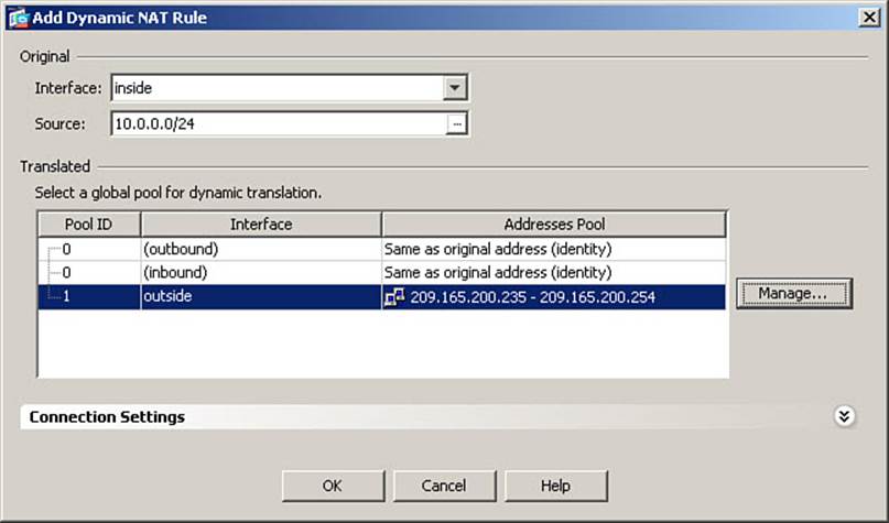
Figure 7-8. Binding a Global Pool to a NAT Rule
The final step to completing the definition of a NAT rule is to bind the original address and ingress interface to a particular translation pool defined on the egress interface for this traffic. You have defined as eligible for translation, original addresses of 10.0.0.0/24, which ingress the inside interface, and have created a global pool of 209.165.200.235-254 to be used when the outside interface is the egress interface. To bind these together, select the newly configured pool by clicking it, as shown in Figure 7-8, and then click the OK button.
Tip
When you are configuring from the CLI, where changes are immediate (whereas clicking Apply is necessary in Cisco ASDM), it is advisable to create the global pool first, and then enter the nat command, because as soon as you enter the nat command, eligible hosts may begin to attempt connections. When the ASA attempts to match these hosts to a global pool and finds none, it will drop the packets. Also, it will record the fact that the attempting host has no translation rule, and drop packets for the duration of the xlate timeout value, unless an administrator manually clears the translation slot.
The final step in this scenario is to adjust the global translation idle timer (the xlate timeout value) from the default of 3 hours to 1 hour. To do this, navigate to Configuration > Firewall > Advanced > Global Timeouts. Figure 7-9 shows the Global Timeouts window. There are many global timeout values tracked by a Cisco ASA.
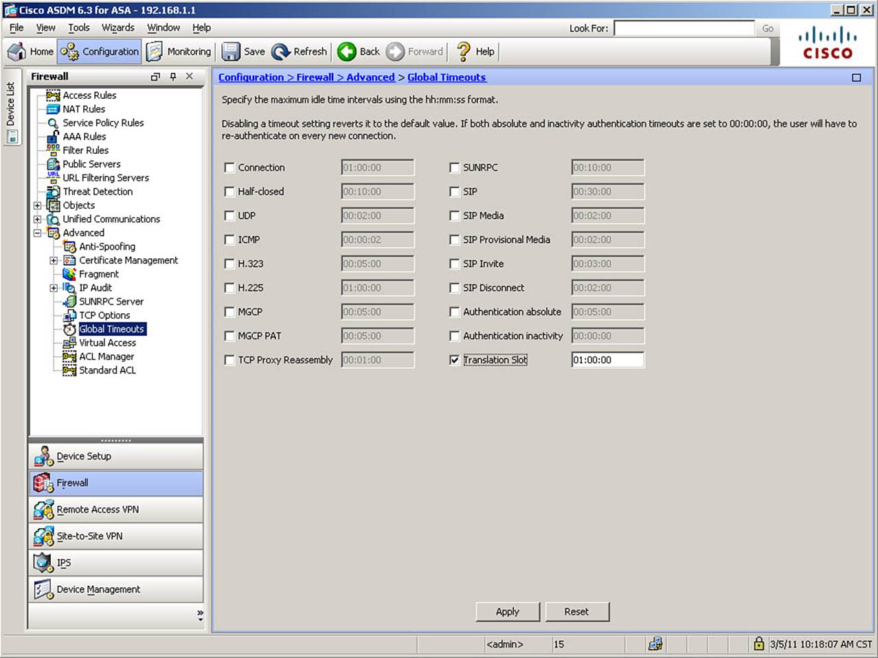
Figure 7-9. Changing the xlate Timeout
As shown Figure 7-9, to change the xlate (translation slot) timeout value, check the Translation Slot check box. The field will no longer be dimmed. Enter a new timeout value. The figure shows the new timeout value being set as 1 hour (01:00:00).
Click OK to save the changes made in this window. Finally, click Apply to send the configuration changes to your ASA.
The CLI commands generated by the changes made are as follows:
nat (inside) 1 10.0.0.0 255.255.255.0
global (outside) 1 209.165.200.235-209.165.200.254 netmask 255.255.255.224
timeout xlate 1:00:00
If you are configuring the ASA from the CLI, you can enter these commands directly in global configuration mode. Note that two commands exist to define dynamic NAT and are associated with each other through the use of the same NAT ID number, which is 1 in this example.
Any individual host can match only one NAT rule for any given connection. The practical significance of this is that any given original address can be bound to only one dynamic NAT ID at a time. So, in the example, a host on the 10.0.0.0/24 subnet would be bound to NAT ID 1, regardless of the egress interface. For example, if a host on the inside subnet were to communicate with the DMZ subnet, and such connections were dynamically translated, we would need a global address pool, with a NAT ID of 1, on the DMZ interface for the internal host to be successfully translated. This is perfectly acceptable—nothing implies that a NAT ID can be used on only one interface or must be unique in any way. Examples of multiple interfaces with NAT appear in the next section.
Configuring Dynamic Inside PAT
Dynamic inside NAT creates one-to-one translations of local IP addresses to global IP addresses. Dynamic inside PAT, by contrast, creates many-to-one translations, allowing numerous local IP addresses to share a single global IP address. It does so by creating a temporary translation of both the original IP address and the original source port number to a global IP address and unique global port number, for each translated session (the term session is used to indicate a unique, bidirectional communication and therefore is used even when referring to UDP, which is connectionless). These translations are created and added to the translation table for each outbound TCP or UDP session requiring PAT, and are deleted and removed from the table when the OSI Layer 4 session closes. The port numbers are assigned based on an internal algorithm and will appear random.
Note
Older versions of the OS on the Cisco PIX Firewall and ASA assigned PAT port numbers sequentially, beginning with 1024 and moving upward, for host connections initiated from port numbers 1024 and higher.
Because each OSI Layer 4 session uses a separate translation slot, the size of the translation table can grow very large in a production network.
To provide a global IP address for PAT, you can define an available IP address, or you can configure the use of the ASA’s IP address on the egress interface. Using the ASA interface IP is particularly useful in environments where you are provided only one IP address, usually dynamically assigned, by an ISP, but it is not limited to such instances.
Like dynamic NAT, dynamic PAT is typically used for client hosts that need outbound connectivity only, and when there are not enough global IP addresses available to assign a unique global address to each local host.
The configuration of dynamic inside PAT is similar to that of dynamic inside NAT. The only difference, in fact, is that when defining the global address pool, instead of using a range of addresses, you specify a single IP address (or the ASA interface).
To present a multi-interface translation scenario, the PAT configuration example will proceed as if there are no current translation rules present on the ASA. You will define the use of PAT for hosts on the inside interface when they initiate communication with hosts reachable through either the outside or DMZ interfaces of the ASA. Further, there will be occasions when hosts on the DMZ need to initiate connectivity to the outside world, so this example will configure PAT for those connections as well.
To begin the process, once again navigate to Configuration > Firewall > NAT Rules and click Add > Add Dynamic NAT Rule to create a new rule and to define an original interface and IP address range that will be subject to translation. In our example, this would be the inside interface and the 10.0.0.0/24 subnet. In the Add Dynamic NAT Rule dialog box, click Manage to open the Manage Global Pool dialog box, and then click Add to open the Add Global Address Pool dialog box, displayed in Figure 7-10. Here, you will define a single global address to be used for PAT.
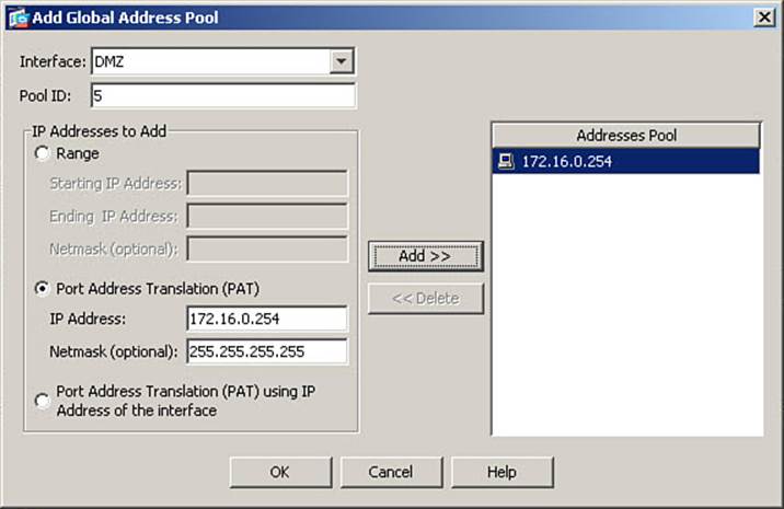
Figure 7-10. Configuring a PAT Global Address
In the Interface field, select the egress interface where the PAT address will be used. In Figure 7-10, the DMZ interface has been selected. Enter a valid NAT ID number in the Pool ID field. In the figure, the pool ID has been set to 5. To configure the use of PAT, in the IP Addresses to Add area, click the Port Address Translation (PAT) radio button.
In the IP Address field, enter the global IP address that will be used for PAT. In Figure 7-10, the address that will be used is 172.16.0.254. Even though PAT implies the use of a single IP address, there is an optional Netmask field. This should always be set to 255.255.255.255 for PAT, as it is in Figure 7-10.
Click the Add button to move the address you defined to the Addresses Pool list. Then, click OK to complete this PAT address creation and return to the Manage Global Pool dialog box.
Note
You can specify more than one PAT address with the same pool ID on the same interface. If port assignments are exhausted on the first address listed (which can occur in high-traffic environments where tens of thousands of concurrent sessions occur and use all ports in the 1024–65535 range), new port translations will occur using the second address in the list, and so on.
You have now configured the use of PAT when communicating with hosts reachable through the DMZ interface. To create another PAT rule, for use when communicating with hosts reachable through the outside interface, once again click Add to open the Add Global Address Pool dialog box, displayed in Figure 7-11. This time, you will configure the use of PAT by using the ASA interface address as the PAT address.
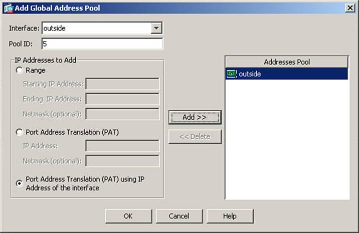
Figure 7-11. Configuring PAT Using the Interface Address
In Figure 7-11, the outside interface has been selected. Because the same local hosts will be using this translation rule, whether communicating through the DMZ or outside interface, the same NAT ID number must be used. Therefore, the figure shows this value once again being set to 5.
In the IP Addresses to Add area, click the Port Address Translation (PAT) Using IP Address of the Interface radio button instead of specifying a separate IP address.
Click OK in the Add Global Address Pool dialog box, and then click OK in the Manage Global Pool dialog box, to complete the definition of the new PAT addresses and return to the Add Dynamic NAT Rule dialog box.
Figure 7-12 shows the Add Dynamic NAT Rule dialog box, which now shows the two newly defined PAT addresses with the same NAT ID number listed in the Pool ID column.
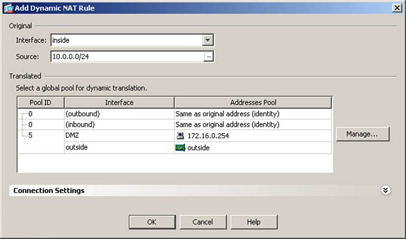
Figure 7-12. Binding a PAT Address to a NAT Rule
To complete the definition of the new PAT translation rules for hosts on the inside subnet, select the newly configured PAT “pool” by clicking it, and then click the OK button.
The final portion of this configuration scenario is to configure PAT translation for hosts on the DMZ subnet, when initiating communication to hosts on the outside. These hosts will use the same “pool” as the inside hosts—namely, the PAT rule using the outside interface IP address.
To associate a new set of original (local) host addresses with an existing pool, navigate once again to Configuration > Firewall > NAT Rules and then click Add > Add Dynamic NAT Rule to open the Add Dynamic NAT Rule dialog box. Figure 7-13 shows an example of defining a new source IP range to use an existing global pool.
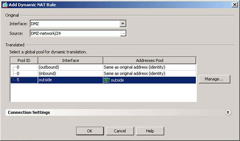
Figure 7-13. Binding an Existing PAT Address to a NAT Rule
In the Original area of the Add Dynamic NAT Rule dialog box, from the Interface drop-down list, select the ingress interface for this NAT rule. In Figure 7-13, the DMZ interface is selected.
Next, in the Source field, enter the local IP address or address range that will be subject to this NAT rule. Optionally, you may click the ellipsis (...) button to choose an IP address or range that has already been defined within Cisco ASDM. In Figure 7-13, the ellipsis was clicked and the DMZ network was selected.
The last step is to select Pool ID 5 in the Translated area. Click OK to complete the binding and return to the NAT Rules window. Figure 7-14 shows the results in the NAT Rules window.
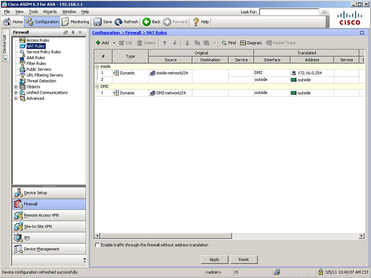
Figure 7-14. Completed NAT Rules Display
Note the number column (column header #). The numbers shown here are a strict sequence, starting at 1, and show how many NAT rules exist on the interface. It is not related to the NAT ID number configured in the NAT rules.
Finally, click Apply to send the configuration changes to your ASA.
The CLI commands generated by the changes made are as follows:
nat (DMZ) 5 172.16.0.0 255.255.255.0 tcp 0 0 udp 0
nat (inside) 5 10.0.0.0 255.255.255.0 tcp 0 0 udp 0
global (outside) 5 interface
global (DMZ) 5 172.16.0.254 netmask 255.255.255.255
If you are configuring the ASA from the CLI, you can enter these commands directly in global configuration mode. For now, do not worry about the tcp and udp parameters; they are discussed elsewhere.
Note
Note the use of the keyword interface in the sample configuration. Not only is this convenient for situations where the ASA is dynamically addressed (as the PAT address will change when the interface address is changed), but is required, as attempting to enter the IP address of the ASA interface when entering this command would generate an error.
Configuring Dynamic Inside Policy NAT
In production networks, you might regularly encounter situations in which local hosts, communicating with different destinations through the same egress interface of the ASA, are required to have different translation rules for each set of destination addresses. In such situations, dynamic NAT or PAT as seen thus far is insufficient to handle the required translations. Examples of such situations include communication across a VPN tunnel to a network that has addressing conflicts with the local network (possibly even overlapping IP address spaces), or connections to application vendors that require your entire network to appear to the application as a single, authorized IP address, and the PAT address normally used for these originating hosts cannot be used for some reason (perhaps because only a subset of local hosts using dynamic PAT are authorized to use the application).
Cisco ASAs support a feature known as policy NAT (or policy PAT), which allows you to specify which specific traffic flows (rather than only which source IP addresses) will be subject to a translation rule. You do this by defining a policy using an ACL, wherein flows defined with a permit entry become eligible for the policy NAT rule you create. ACL configuration is covered in detail in Chapter 8, but this chapter presents some examples for the purpose of illustrating policy NAT rule creation. If you do not fully understand the examples because you do not understand the ACL used, feel free to return and read this section after you read Chapter 8.
You can combine policy NAT with dynamic inside NAT and create dynamic inside policy NAT rules. In this case, you will translate the source IP addresses of your local hosts dynamically, depending on the specific definition of traffic flows defined in an ACL.
To demonstrate a case where dynamic inside policy NAT could be used, we will use the following configuration scenario: The original dynamic NAT configuration from earlier in the chapter is configured on the ASA. The PAT rules from the last section are not present. Several hosts in the 10.0.0.0/24 inside subnet are authorized to connect to a vendor application server on the Internet. This vendor requires all users coming from your organization to appear to their server as a single IP address. Because you are using one-to-one dynamic inside NAT, each internal host has a unique global address when translated.
Thus, you need to create a dynamic inside policy NAT rule to translate internal hosts to use a configured PAT address if they are communicating with the vendor application server, but still use the previously defined NAT rule (pool ID 1) when connecting elsewhere on the Internet.
The configuration scenario presented is based on the scenario in the preceding text. It assumes that all required routing is properly configured and that access rules allow all required communication between these hosts and the outside world.
To configure a dynamic inside policy NAT rule, navigate to Configuration > Firewall > NAT Rules and then click Add > Add Dynamic Policy NAT Rule to open the Add Dynamic Policy NAT Rule dialog box, shown in Figure 7-15. From this dialog box, you will define your policy for traffic flows subject to this new translation rule.
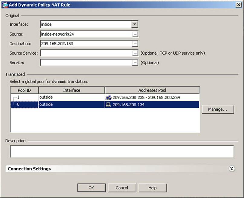
Figure 7-15. Configuring Dynamic Policy NAT Rule
In the Original area, from the Interface drop-down list, choose an interface that will be the ingress interface for hosts with local addresses to be translated. In Figure 7-15, the inside interface is selected.
In the Source field, enter local addresses, or use the ellipsis button to choose addresses already defined in Cisco ASDM. In the example, the inside-network object known to ASDM has been selected.
Next, in the Destination field, enter the destination address(es) to which these hosts will be connecting, to define specific traffic flows subject to translation. In Figure 7-15, the address 209.165.202.150 is entered (no mask is necessary because ASDM defaults to a /32 mask). This is the vendor application server address.
Optionally, you can further refine the definition of traffic flows subject to translation by selecting a service in the Service field, to specify the destination service (destination port) that the local hosts are connecting to when they become subject to this translation rule. In Figure 7-15, no service is selected, so all traffic destined to the vendor application server will be subject to this translation rule.
Now that you have defined a policy to select traffic flows subject to this translation rule, assign a PAT global address to this rule, using the same procedure covered in earlier examples. Click the Manage button on the right side of the Translated area to define the PAT address. This scenario assumes a Pool ID of 8 was used, with a PAT address of 209.165.200.134. Traffic flows subject to this translation policy will have the source IP address of the local host translated to this PAT address when completing the connection.
Note
This demonstrates an important concept in translation rules. It was stated earlier that any local host could match only one translation rule for any particular traffic flow. Policy NAT rules are evaluated before “regular” NAT rules, so even though this rule uses a pool ID of 8, it will be used, rather than pool ID 1, when packets match the defined policy. The pool IDs do not dictate the order of evaluation.
Select the newly created PAT pool. Click OK in the Add Dynamic Policy NAT Rule dialog box to complete the definition of the policy NAT rule. Finally, click Apply to send the changes to the ASA.
The CLI commands generated by the changes made are as follows:
access-list POLICY-NAT-ACL line 1 extended permit ip 10.0.0.0 255.255.255.0 host
209.165.202.150
!
nat (inside) 8 access-list POLICY-NAT-ACL tcp 0 0 udp 0
global (outside) 8 209.165.200.134 netmask 255.255.255.255
The ACL name is changed from that assigned by ASDM for readability. If you are configuring the ASA from the CLI, you can enter these commands directly in global configuration mode.
Note
Deny access control entries (ACE) are not supported inside policy NAT ACLs. You should only define flows unidirectionally, using the local network as the source in the policy NAT ACL.
Verifying Dynamic Inside NAT and PAT
To examine existing translation table entries (translation slots), use the show xlate or show xlate details command.

Example 7-1 shows the use of the show xlate command based on the original configuration of dynamic inside NAT only. The output shows the number of translation slots currently in use, and the highest number of translation slots concurrently in use since the last reboot of the ASA. Finally, all active translation slots are displayed, with the keyword Global indicating the translated address and the keyword Local indicating the original address. Note that no interface information is contained in the output.
Example 7-1. show xlate Command Output (NAT)
FIREWALL# show xlate
1 in use, 3 most used
Global 209.165.200.235 Local 10.0.0.101
Example 7-2 shows the use of the show xlate command based on the PAT configuration created in the multi-interface scenario presented earlier in the chapter. For each translation slot entry, the keyword PAT appears before the Global keyword. Along with the global and local IP addresses, the number appearing in parentheses is the source port number in the packet, after translation (global) and prior to translation (local).
Example 7-2. show xlate Command Output (PAT)
FIREWALL# show xlate
3 in use, 10 most used
PAT Global 209.165.200.226(50595) Local 10.0.0.101(49298)
PAT Global 209.165.200.226(25788) Local 172.16.0.51(49297)
PAT Global 209.165.200.226(48335) Local 10.0.0.101(62474)
Example 7-3 shows the use of the show xlate detail command based on the configuration combining dynamic inside NAT with dynamic inside policy PAT. The show xlate detail command adds a table of Flag identifiers, for help in understanding the flags listed in the individual translation slot entries. Each translation slot entry also includes information on interfaces involved in the traffic flow. Each entry lists the ingress interface and original (local) address first, followed by the egress interface and translated (global) address. PAT entries indicate whether the protocol in use was TCP or UDP. Translations based on policies (ACLs) show the name of the ACL that defines the policy. Finally, entries contain flags denoting the type of NAT applied. Dynamic translations contain the i flag and PAT translations contain the r flag, for example.
Example 7-3. show xlate detail Command Output
FIREWALL# show xlate detail
2 in use, 8 most used
Flags: D - DNS, d - dump, I - identity, i - dynamic, n - no random,
r - portmap, s - static
NAT from inside:10.0.0.101 to outside:209.165.200.240 flags i
TCP PAT from inside:10.0.0.101/49274 to outside(POLICY-NAT-ACL):209.165.200.134/
17637 flags ri
To manually clear the translation table and return all allocated slots to the pool for assignment, use the clear xlate command. This is highly recommended (Cisco even uses the word “required,” although this is not entirely accurate) whenever translation rules are changed. There are variations on this command (shown in the section, “Command Reference to Check Your Memory,” at the end of this chapter) that allow you to clear only certain translation slots, instead of the entire table. Some active connections that require translation might fail if the underlying translation is cleared, so it is important, in production environments, to clear only those translation slots necessary for your purpose.
Configuring Static Inside NAT
Static inside NAT creates permanent, fixed translations between a local address and a global address. Translation slots created using static translation rules are always present in the translation table, and are persistent across reboots. They have no idle timer leading to expiration. If you delete a static NAT rule from the ASA, the associated entries in the translation table are automatically removed; however, existing sessions remain functional unless manually cleared by an administrator.
Because translation slots based on static translation rules are always active, hosts from less secure networks can initiate communications to the statically translated local hosts, as long as the access list rules on the ASA permit such traffic. These factors make static inside NAT ideal for servers that need to be accessed from less secure interfaces, where the address configured on the server needs to be translated.
Figure 7-16 shows an example of this concept. There are two application servers, a web server and an FTP server, located on the DMZ network.
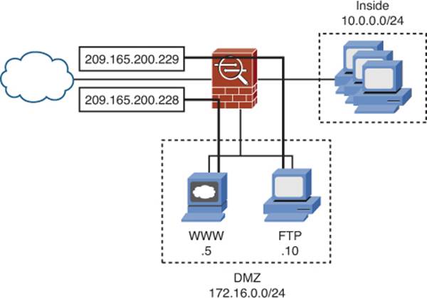
Figure 7-16. Static Inside NAT Example
The IP addresses configured on the hosts are private IP addresses—172.16.0.5 for the web server and 172.16.0.10 for the FTP server. These servers are regularly accessed by clients on the Internet. They must therefore have fixed IP addresses, which can be registered in DNS records that Internet-based hosts will use to find them. Because the private IP addresses configured on the servers cannot be registered in global DNS entries, these servers will use static inside NAT to provide fixed translations to global IP addresses.
Figure 7-16 shows an example where the web server’s local IP address of 172.16.0.5 will be translated to a global IP address of 209.165.200.228, and the FTP server’s local IP address of 172.16.0.10 will be translated to a global IP address of 209.165.200.229. When you create DNS records for these hosts, you will use those global addresses. When users on the Internet want to access these hosts, the packets they send will have one of those addresses as the destination IP address. The ASA will be responsible for translating that destination IP and forwarding the traffic to the correct server.
Note that static translations on a Cisco ASA are automatically bidirectional. In other words, unless you create translation rules that will supersede the static translations for these two hosts, if they were to initiate connectivity to hosts reachable through the outside interface of the ASA, their source IP address would be translated to the same global IP address at all times. For example, if the web server with local address 172.16.0.5 connected to an external host, perhaps to download updates for installed software packages, the source address in such packets would be translated to 209.165.200.228 before being forwarded by the ASA through the outside interface.
Recall the four pieces of information necessary for an ASA to perform NAT:
• Original source IP address (and port) in the packet
• Interface where the original packet enters the ASA (ingress interface)
• Interface where the packet will exit the ASA (egress interface)
• Translated address (and, optionally, port) to insert into the packet
When dynamic inside NAT was defined, the original IP address and interface were defined with the nat command, and the mapped (translated) IP address and interface were defined with the global command. These two commands were bound together by using the same NAT ID parameter in both.
Static inside NAT is different, in that all four required pieces of information are defined in a single command (and in a single ASDM window).
To begin the process, navigate to Configuration > Firewall > NAT Rules, and then click Add > Add Static NAT Rule to create a new rule. The Add Static NAT Rule dialog box will open, as shown in Figure 7-17, where you define a new static inside NAT rule.

Figure 7-17. Configuring a Static NAT Rule
In the Original area, you define the actual IP address of the host being translated (sometimes called real_ip in documentation) and the ingress interface for traffic arriving from that host (real_ifc). From the Interface drop-down list, select the ASA interface through which the host subject to translation is reached (where packets from said host will ingress to the ASA). In Figure 7-17, the DMZ interface is selected.
In the Source field, enter the local (real) IP address of the host that will be translated. In Figure 7-17, 172.16.0.5 is entered, defining the web server.
In the Translated area, you define the global address to which the host will be translated (called mapped_ip) when traffic from that host egresses the ASA on a selected interface (mapped_ifc). In this example, you are creating a mapping for the web server on the outside interface, so, in the figure, the outside interface is selected from the Interface drop-down list.
Click the Use IP Address radio button and enter the global (translated/mapped) IP address in the field. It is important that you not use a global IP address that is also defined as part of a global address pool on the same interface. In Figure 7-17, the global IP address of 209.165.200.228 is entered.
Click OK to accept the new static translation definition and close the Add Static NAT Rule dialog box. Using the same procedure, define the static translation for the FTP server, from real interface DMZ and address 172.16.0.10 to mapped interface outside and address 209.165.200.229, per the scenario information. Then click Apply to send the changes to the ASA.
The CLI commands generated by the changes made are as follows:
static (DMZ,outside) 209.165.200.228 172.16.0.5 netmask 255.255.255.255 tcp 0 0
udp 0
static (DMZ,outside) 209.165.200.229 172.16.0.10 netmask 255.255.255.255 tcp 0 0
udp 0
If you are configuring the ASA from the CLI, you can enter these commands directly in global configuration mode.
Note
If you are configuring static commands from the CLI, it is important to remember that the order of the interfaces is real and then mapped (or local and then global, if you prefer), but the order of IP addresses is mapped and then real (global and then local). Also, there is no space after the comma when specifying interface names. Inserting a space will generate a syntax error.
Note
When you are configuring static translations, in the absence of a configured network mask, a /32 netmask is assumed (the translation is for a single host). Most other commands that have a netmask value as an available parameter default to a classful netmask if none is explicitly configured.
Configuring Network Static Inside NAT
Static inside NAT is not limited to defining host-specific translations. It is possible, with a single static translation, to statically translate an entire range of local addresses to a global address range of the same size.
Consider, for example, the network diagram shown in Figure 7-18. There are 32 servers located in the DMZ: 172.16.0.32–172.16.0.63. You have obtained from your ISP a global IP address block of 209.165.201.0/27, which is 32 addresses in size.
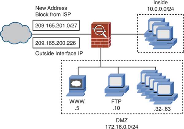
Figure 7-18. Network Static Inside NAT Scenario
Note that the ASA IP address of 209.165.200.226 is not part of the same network as the addresses assigned by your ISP. This is perfectly acceptable. By default, the ASA will act as a proxy ARP responder for any global addresses configured on its interfaces—it does not need to be attached to the network itself.
Note
When using address blocks for translation, as long as the ASA interface is not part of the defined network, it is not necessary to reserve out the addresses that would normally represent the network identifier (.0) and the directed broadcast address (.31). As long as the addresses are routed toward the firewall, all addresses in the block can be used for host translations.
So, you have 32 servers that will need static translations, and you have a block of 32 global addresses. If you were to use host-specific static translations, you would need to configure 32 of them. Is there a way to accomplish this with less configuration work? Yes! Network static translations (sometimes simply called “net statics”) are the answer to this need.
To begin the process, navigate to Configuration > Firewall > NAT Rules, and then click Add > Add Static NAT Rule to create a new rule. The Add Static NAT Rule dialog box opens, as shown in Figure 7-19.
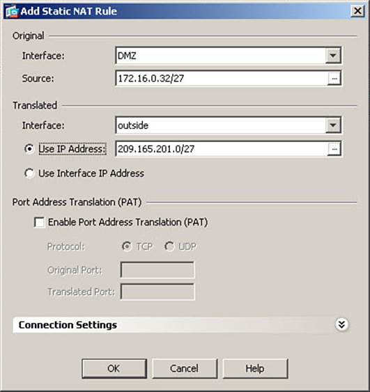
Figure 7-19. Configuring a Network Static Inside NAT Rule
In the Original area, from the Interface drop-down list, select the ASA interface through which the host range subject to translation is reached (where packets from said host range will ingress to the ASA). In Figure 7-19, the DMZ interface is selected.
In the Source field, enter the local (real) IP address range of the hosts that will be translated, including a netmask value. In Figure 7-19, 172.16.0.32/27 is entered, defining the range of addresses from 172.16.0.32 through 172.16.0.63.
In the Translated area, you define the global address range and interface used for this translation. In Figure 7-19, the outside interface is selected from the Interface drop-down list.
Click the Use IP Address radio button and enter the global IP address range in the field, including a netmask value (the same as used to define the original address range). In Figure 7-19, the global IP address range of 209.165.201.0/27 is entered.
Note
The netmask value defines both the size of the block being translated and the specific bits being translated. In this example, the host portion of the original IP addresses is 32–63, but the global address range is 0–31. However, you are translating only the first 27 bits of the original address. So, for example, 172.16.0.39
(10101100.00010000.00000000.00100111) is translated to 209.165.201.7 (11010001. 10100101. 11001001.00000111). The first 27 bits are translated to equal the first 27 bits of the address in the Use IP Address field, and the last 5 bits are left unchanged.
Click OK to accept the new static translation definition and close the Add Static NAT Rule dialog box. Then, click Apply to send the changes to the ASA.
The CLI command generated by the changes made is as follows:
static (DMZ,outside) 209.165.201.0 172.16.0.32 netmask 255.255.255.224 tcp 0 0
udp 0
If you are configuring the ASA from the CLI, you can enter this command directly in global configuration mode.
Note
It is not possible to define many-to-one static translations prior to OS version 8.3. For example, you can translate an original host address to a translated host address, or you can translate a block of original addresses to a block of translated addresses, as just demonstrated. You cannot, however, translate a block of original addresses to a single host translated address, statically (although you can perform port-redirection for inbound sessions only, as discussed in the following section, “Configuring Static Inside PAT”). This deficiency of function is addressed in OS versions 8.3 and later.
Configuring Static Inside PAT
Using static inside PAT, you can create a fixed translation from a local host IP address and local Layer 4 port (for TCP or UDP) to a global IP address and global Layer 4 port. Static inside PAT is useful when you want to allow inbound connectivity to a number of local servers, using a single global IP address. Remember, of course, that an interface access list on the ASA would still need to be configured to allow such connections (interface access lists are discussed in Chapter 8). It also allows you to reuse a global IP address that is used for dynamic inside NAT/PAT (because outgoing sessions will use port numbers of 1024 and higher) to also support inbound connectivity to servers on specific global ports (which will generally be 1023 and below), forwarded to specific local hosts, on specific local ports.
Static inside PAT has the following characteristics:
• It supports only incoming sessions to the configured global address and port. If the local host also needs to initiate outgoing sessions, you should use either inside NAT or PAT rules to accomplish this.
• It supports the use of the ASA interface as the global address.
• It allows port redirection from a well-known global port to a custom local port, or vice versa. For example, a local web-based application server listens on the well-known TCP port 80. Incoming connections use a custom TCP port of 8080, and the static inside PAT rule redirects these to TCP port 80 when forwarding to the local server.
• It allows port redirection so that multiple local servers, using unique local ports, can share a single global IP address. For example, assume you have two local servers: a web-based application server listening for HTTPS on customized TCP port 8443 and a mail server listening for SMTP on TCP port 25. You have only one global IP address available. Incoming connections to the global IP address, on well-known TCP port 443, are forwarded to the web server on the custom port. Incoming connections to the same global IP address, on port 25, are forwarded to the mail server, still using port 25.
Figure 7-20 shows a network diagram based on the example just described. This is the basis for the configuration scenario to demonstrate the use of static inside PAT.
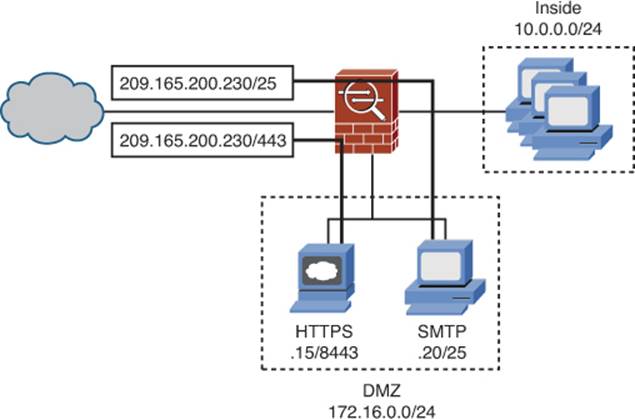
Figure 7-20. Static Inside PAT Scenario
You have two servers located on the DMZ segment. The first, with a local IP address of 172.16.0.15, hosts a secure web-based application and listens for HTTPS connections on customized TCP port 8443. The second is a mail server, with a local IP address of 172.16.0.20, and listens for SMTP connections on TCP port 25. You have only one global IP address available for use, 209.165.200.230.
You will configure static inside PAT so that the two local servers, listening on unique local ports, can share the single available global IP address.
To begin the process, navigate to Configuration > Firewall > NAT Rules, and then click Add > Add Static NAT Rule to create a new rule. The Add Static NAT Rule dialog box will open, as shown in Figure 7-21.
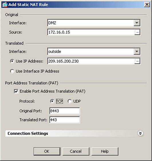
Figure 7-21. Configuring a Static Inside PAT Rule
In the Original area, from the Interface drop-down list, select the ASA interface through which the hosts subject to translation are reached (where packets from said hosts will ingress to the ASA). In Figure 7-21, the DMZ interface is selected.
In the Source field, enter the local (real) IP address of the first server that will be translated. In Figure 7-21, 172.16.0.15 is entered, defining the secure web-based application server.
In the Translated area, select the interface where you will map the global IP address used in this translation. In Figure 7-21, the outside interface is selected from the Interface drop-down list.
Click the Use IP Address radio button and enter the global IP address in the field. In Figure 7-21, the global IP address of 209.165.200.230 is entered.
Note
Optionally, you could click the Use Interface IP Address radio button to use the IP address of the selected interface (outside in this example) as the global IP address used for this translation rule.
In the Port Address Translation (PAT) area, check the Enable Port Address Translation (PAT) check box. This will make the fields below this available for editing.
Next, select the radio button for the protocol for which you are translating ports: TCP or UDP. In Figure 7-21, the TCP radio button is selected.
In the Original Port field, enter the actual port on which the server is configured to listen. In Figure 7-21, port 8443 is configured.
In the Translated Port field, enter the port that will be specified as the destination port for inbound connections. This server requires port redirection, and port 443 is configured in this field.
Click OK to accept the new static translation definition and close the Add Static NAT Rule dialog box. Using the same procedure, define the static translation for the mail server, from real interface DMZ and address 172.16.0.20 to mapped interface outside and address 209.165.200.230, this time using TCP port 25 as both the original and translated port, because port redirection is not used for the mail server. Then click Apply to send the changes to the ASA.
The CLI commands generated by the changes made are as follows:
static (DMZ,outside) tcp 209.165.200.230 443 172.16.0.15 8443 netmask
255.255.255.255 tcp 0 0 udp 0
static (DMZ,outside) tcp 209.165.200.230 25 172.16.0.20 25 netmask
255.255.255.255 tcp 0 0 udp 0
If you are configuring the ASA from the CLI, you can enter these commands directly in global configuration mode.
These translations allow outside hosts to access either server in the DMZ by connecting to their global IP address and global port (assuming that access rules have been created to permit such connections). To access the secure web-based application server, outside hosts would connect to 209.165.200.230, TCP port 443. To access the mail server, outside hosts would connect to 209.165.200.230, TCP port 25.
Note
Static PAT allows you to use the same global IP address for many different static rules, provided the port is unique for each rule. You cannot use the same global IP address for multiple static NAT rules.
Configuring Static Inside Policy NAT
As previously mentioned, in production networks, local hosts communicating with different destinations through the same egress interface of the ASA regularly are required to have different translation rules for each set of destination addresses. Dynamic inside policy NAT allows you to provide different translation rules depending on the specific traffic flows involved. Static inside policy NAT does the same thing, while providing a fixed, rather than dynamic, address translation for the original local host.
The most common example where static inside policy NAT would be required is communication across a VPN tunnel to a network that has addressing conflicts with the local network (possibly even overlapping IP address spaces).
As with dynamic policy NAT, this is done by defining a policy using an ACL, wherein flows defined with a permit entry become eligible for the static policy NAT rule you create. Permitted traffic flows will have their original source IP address statically translated to the global IP address provided in the static translation rule.
To demonstrate a case where static inside policy NAT could be used, consider the following configuration scenario: Your company, Company A, recently acquired another company, Company B, and you have established a VPN connection between the two sites. Users at Company B must be able to communicate with your mail server on the DMZ subnet (172.16.0.20:25), and your mail server must be able to communicate bidirectionally with the Company B mail server, which will eventually be phased out. However, Company B has a VPN with a vendor that also uses the 172.16.0.0/24 address space. Obviously, you cannot force the vendor to re-address its network.
Note
It is the fact that you need to allow bidirectional traffic initiation with the remote network that makes the use of static inside policy NAT necessary. The remote network must have a fixed IP address to which it connects in order to reach the local server, but the local server must also be able to initiate connectivity to the remote network. If only the remote network initiated connectivity, dynamic inside policy PAT could be used. If only the local host initiated connectivity, dynamic inside NAT might be able to be used.
Thus, you need to create a static inside policy NAT rule, which will allow these users to connect to your mail server using an address that will not conflict with their existing routing plan, while the server still uses the previously defined static PAT rule when connecting to the Internet.
Figure 7-22 presents a network diagram based on the scenario just described.
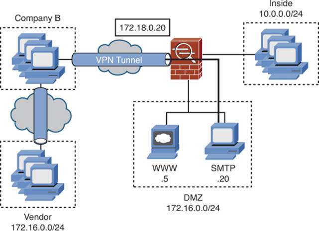
Figure 7-22. Static Inside Policy NAT Scenario
To begin the process, navigate to Configuration > Firewall > NAT Rules, and then click Add > Add Static Policy NAT Rule to create a new rule. The Add Static Policy NAT Rule dialog box will open, as shown in Figure 7-23.
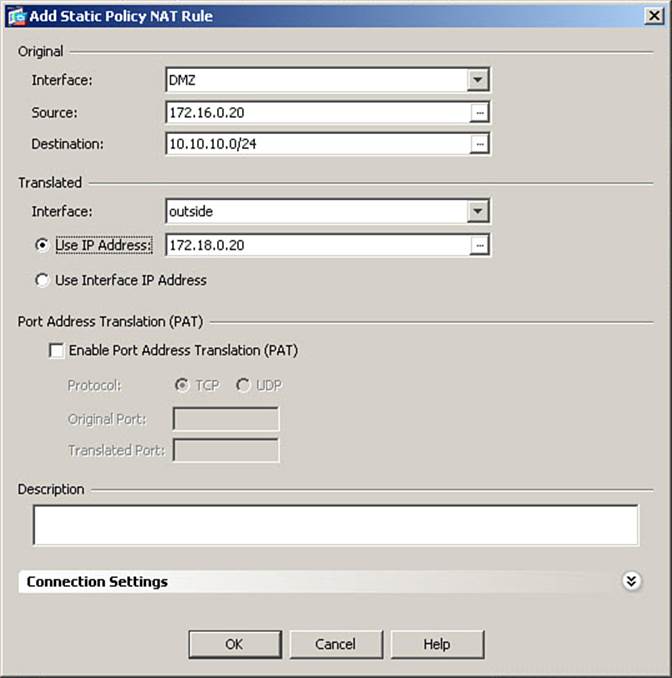
Figure 7-23. Configuring a Static Inside Policy NAT Rule
In the Original area, from the Interface drop-down list, select the ASA interface through which the host subject to translation is reached. In Figure 7-23, the DMZ interface is selected.
In the Source field, enter the local IP address of the host that will be translated. In Figure 7-23, 172.16.0.20 is entered, defining the mail server.
Next, in the Destination field, enter the destination address(es) to which this host will be communicating, to define specific traffic flows subject to translation. In Figure 7-23, the address 10.10.10.0/24 is entered, specifying the internal network of Company B.
In the Translated area, select the interface where you will map the global IP address used in this translation. In Figure 7-23, the outside interface is selected from the Interface drop-down list.
Click the Use IP Address radio button and enter the global IP address in the field. In Figure 7-23, the global IP address of 172.18.0.20 is entered.
Click OK to accept the new static policy NAT definition and close the Add Static Policy NAT Rule dialog box. Then click Apply to send the changes to the ASA. Because the policy NAT rule just defined uses the same local address and same port pair as an existing static rule, Cisco ASDM will present you with a Warning message. Note that Warnings indicate an unusual condition that you should verify, whereas Errors indicate that the configuration is invalid.
The CLI commands generated by the changes made are as follows:
access-list POLICY-NAT-ACL2 line 1 extended permit ip host 172.16.0.20 10.10.10.0
255.255.255.0
!
static (DMZ,outside) 172.18.0.20 access-list POLICY-NAT-ACL2 tcp 0 0 udp 0
The ACL name is changed from that assigned by ASDM for readability. If you are configuring the ASA from the CLI, you can enter these commands directly in global configuration mode.
Although the policy is configured for outgoing traffic, remember that the ASA will also apply the same condition to incoming traffic. That is, if mail server 172.16.0.20 is initiating connectivity to the 10.10.10.0/24 network, its source address will be translated to 172.18.0.20. Likewise, if hosts on the 10.10.10.0/24 network send traffic to 172.18.0.20, and this traffic is routed across the VPN to the ASA, after decryption, the destination address in the packets will be changed from 172.18.0.20 to 172.16.0.20, before being forwarded to the mail server on the DMZ.
Note
Static inside policy PAT can be defined in the same manner, by enabling PAT and specifying original and translated port numbers, after configuring the global IP address.
Verifying Static Inside NAT and PAT
As with dynamic inside NAT and PAT, static inside NAT and PAT can be verified using the show xlate or show xlate detail command.
The output of show xlate is the same regardless of whether translations are dynamic or static. There is nothing in the output that indicates a given xlate table entry is based on a static, rather than dynamic, translation rule.
Example 7-4, however, shows the use of the show xlate detail command. The show xlate details command adds a table of Flag identifiers, for help in understanding the flags listed in the individual translation slot entries. Each translation slot entry also includes information on interfaces involved in the traffic flow. Each entry lists the ingress interface and original (local) address first, followed by the egress interface and translated (global) address. PAT entries indicate whether the protocol in use was TCP or UDP. Translations based on policies (ACLs) show the name of the ACL that defines the policy. Finally, entries contain flags denoting the type of NAT applied. Static translations contain the s flag and PAT translations contain the r flag, for example.
Example 7-4. show xlate detail Command Output
FIREWALL# show xlate detail
6 in use, 6 most used
Flags: D - DNS, d - dump, I - identity, i - dynamic, n - no random,
r - portmap, s - static
TCP PAT from DMZ:172.16.0.20/25 to outside:209.165.200.230/25 flags sr
TCP PAT from DMZ:172.16.0.15/8443 to outside:209.165.200.230/443 flags sr
NAT from DMZ:172.16.0.5 to outside:209.165.200.228 flags s
NAT from DMZ:172.16.0.10 to outside:209.165.200.229 flags s
NAT from DMZ:172.16.0.32 to outside:209.165.201.0 flags s
NAT from DMZ:172.16.0.20 to outside(POLICY-NAT-ACL2):172.18.0.20 flags s
To manually clear the translation table and return all allocated slots to the pool for assignment, use the clear xlate command. Because static translations are permanent, if you use the clear xlate command and then immediately use the show xlate command, all statically defined translation slots will appear in the xlate table.
Configuring No-Translation Rules
If you enable NAT control, you must configure translation rules for each host on a more secure interface that requires communication with hosts on less secure interfaces. There are many cases, however, where you will not require NAT for such communication.
For example, if a host on your inside network needs to communicate with a host on your DMZ network, there are no networks in the path that would consider either address nonroutable. As such, there is no reason why the original address of the host cannot remain as it is in the data packets. Other examples are when NAT will be performed by some other device in the data path of the traffic, so the ASA does not need to perform NAT.
Where NAT control is enabled but no translation is required or desired, you must configure no-translation rules to satisfy the requirement that you have addressed how NAT is to be handled for such communication—it is not to be performed.
The Cisco ASA provides three mechanisms that enable you to create translation rules that perform no actual translation:
• Dynamic identity NAT: Creates dynamic identity translation slots in the translation table (where local and global addresses are the same) when hosts on a more secure interface communicate with hosts on less secure interfaces
• Static identity NAT: Creates static identity translation slots in the translation table immediately as they are configured, which can support servers that do not require translation
• NAT bypass (exemption): Allows packets to completely bypass the ASA NAT engine, not creating translation slots at all
Configuring Dynamic Identity NAT
Dynamic identity NAT creates temporary translation slots in the translation table, which “translate” a local address on a specific interface to the same address on all lower-security interfaces. These slots are created by outbound packets from hosts configured for dynamic identity NAT arriving at the ASA. Because these slots come into existence only when outbound traffic occurs, this method is suitable to support only client systems, not servers.
When configuring dynamic identity NAT, you are not able to limit the non-translation to specific global interfaces. For example, you cannot perform normal translation for hosts when they access the outside, while performing identity NAT when the same hosts access the DMZ.
Note
Remember that any given traffic flow can match only a single translation rule. Dynamic identity NAT has the same precedence as any other dynamic NAT rule (non-zero NAT ID pool number). Because the NAT ID number is selected from the nat command that most specifically matches the traffic being analyzed, it is important to ensure that you properly define the source address(es) subject to translation. For example, suppose a host of 10.0.0.75 is the source of packets and the ASA contains the following nat commands:
nat (inside) 0 10.0.0.0 255.255.255.0 tcp 0 0 udp 0
nat (inside) 5 10.0.0.64 255.255.255.192 tcp 0 0 udp 0
The command with NAT ID 5 is a more specific match, based on prefix length, than the identity NAT rule. As such, NAT would be performed, using global pool 5 on the egress interface. It is important to remember that the NAT ID number exists only to bind a nat command to a global pool—it does not imply ordinality (that is, lower numbers are not processed for a match prior to higher numbers). It is not the NAT ID number that determines which nat rule is applied to the traffic, but rather the prefix length to which the nat command address matches the source address in the packets.
Dynamic identity NAT is configured the exact same way as any other dynamic NAT rule, with one exception. To configure dynamic identity NAT, navigate to Configuration > Firewall > NAT Rules and click Add > Add Dynamic NAT Rule. The Add Dynamic NAT Rule dialog box opens, as shown in Figure 7-24. Note that this example assumes that previously defined NAT rules for hosts on the inside interface are no longer in place.
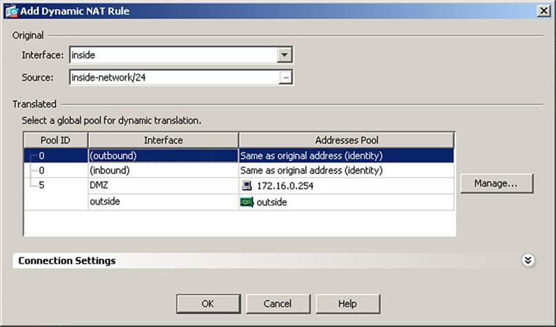
Figure 7-24. Configuring a Dynamic Identity NAT Rule
Define the original interface and IP address(es) subject to this NAT rule as you would for any dynamic inside NAT rule. In Figure 7-24, the inside network 10.0.0.0/24 is defined. Then, in the Translated area, select the predefined pool with NAT Pool ID 0. Because this example is for traffic from a higher-security interface (inside) to a lower-security interface (DMZ), choose the NAT 0 pool with (outbound) listed in the Interface column. The NAT Pool ID of 0 in an outbound direction has special significance to the ASA. It means that specified host addresses will not be translated to any lower-security interfaces, and that translation slots can be created only by outbound communication. Because source addresses on lower-security interfaces are not, by default, translated when traversing the ASA toward a higher-security interface (for example, Internet-sourced traffic trying to reach a web server in the DMZ), inbound identity NAT would be used only in the rare circumstances in which such translation was configured and you needed to override it.
Click OK in the Add Dynamic NAT Rule dialog box to complete the definition of the no-NAT rule. Finally, click Apply to send the changes to the ASA.
The CLI command generated by the changes made follows:
nat (inside) 0 10.0.0.0 255.255.255.0 0 0 tcp 0 0 udp 0
If you are configuring the ASA from the CLI, you can enter this command directly in global configuration mode.
Note
Because the ASA is not performing NAT for the inside network in this example, hosts on the inside network would not be able to communicate with any hosts outside the local network (on the Internet, for example) unless another device in the traffic path, such as an edge (sometimes called perimeter) router, performed NAT.
Configuring Static Identity NAT
Static identity NAT creates permanent translation slots in the translation table that “translate” a local address on a specific interface to the same address on a specific lower-security interface. These slots are created immediately upon configuration. Because these slots always exist, this method is suitable to support servers accepting inbound connections.
When configuring static identity NAT, you are able to limit the non-translation to specific global interfaces. You can therefore perform normal translation for hosts when they access the outside, while performing identity NAT when the same hosts access the DMZ, for example.
The other significant difference with static (versus dynamic) identity NAT is that, access rules permitting, hosts on the less secure interface can access an identity-NAT “translated” server on the more secure interface, using its configured local IP address.
Consider the example shown in Figure 7-25. Your company has an SMTP gateway, 172.16.0.20, on the DMZ network. Mail must pass through this device when moving between the Internet and the internal network. When mail arrives from the Internet, it is passed through various security measures, such as filtering, virus checks, and so on, on the gateway device, and only then is forwarded to your company’s internal mail server, 10.0.0.20, on the inside network. Because both servers are part of the private-address space, no translation is necessary, but because either server may initiate communication, identity NAT must be performed statically, not dynamically.
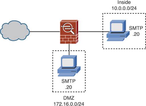
Figure 7-25. Static Identity NAT Scenario
Static identity NAT is configured the exact same way as any other static NAT rules. To configure static identity NAT, navigate to Configuration > Firewall > NAT Rules and click Add > Add Static NAT Rule. The Add Static NAT Rule dialog box opens, as shown in Figure 7-26.

Figure 7-26. Configuring a Static Identity NAT Rule
The example that follows will configure the mail address scenario described in the preceding paragraphs.
Define the original interface and IP address(es) subject to this NAT rule as you would for any static NAT rule. In Figure 7-26, the inside interface is selected and the mail server address of 10.0.0.20 is specified.
In the Translated area, you define the interface where the global address to be configured will be used. In Figure 7-26, the DMZ interface is selected.
Click the Use IP Address radio button and enter the same IP address in this field as you did in the Source field. In Figure 7-26, the IP address 10.0.0.20 is entered in both fields.
Click OK to accept the new static translation definition and close the Add Static NAT Rule dialog box. Then click Apply to send the changes to the ASA.
The CLI command generated by the changes made follows:
static (inside,DMZ) 10.0.0.20 10.0.0.20 netmask 255.255.255.255 tcp 0 0 udp 0
If you are configuring the ASA from the CLI, you can enter this command directly in global configuration mode.
Configuring NAT Bypass (NAT Exemption)
The final, and most preferred, method to perform no translation in situations where NAT control is enabled is NAT bypass (commonly referred to as “NAT 0 with an ACL” or “policy identity NAT”).
NAT bypass allows configured traffic flows to completely bypass the ASA’s NAT engine. Clients and/or servers not requiring translation are thus allowed to communicate without the creation of any translation slots in the translation table (which reduces device processing overhead).
The most common use of NAT bypass is for traffic that will cross the Internet inside a VPN tunnel. Because the original source address is not visible to the Internet, where it would be considered nonroutable, it is generally preferred not to translate this traffic. The other time NAT bypass can be used is when hosts on a more secure interface need to communicate with hosts on a less secure interface, but do not need to accept inbound connections (where the use of static identity NAT is appropriate).
The configuration scenario will be to set up NAT bypass for traffic originating on the inside network and destined for the DMZ network. Because this traffic is contained inside the internal network space, no translation is necessary. Also, in this scenario, hosts on the DMZ never initiate connections to the inside—they are always the server part of the client/server pair.
To configure NAT bypass, navigate to Configuration > Firewall > NAT Rules and click Add > Add NAT Exempt Rule. The Add NAT Exempt Rule dialog box opens, as shown in Figure 7-27. In this dialog box, you will define a full traffic flow policy (which becomes an ACL, hence the common name “NAT 0 with an ACL”) and enable the defined flow to bypass the NAT engine.
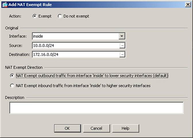
Figure 7-27. Configuring a NAT Bypass Rule
In the Original area, from the Interface drop-down list, select the ASA interface through which the host(s) subject to translation exemption can be reached. In Figure 7-27, the inside interface is selected.
In the Source field, enter the local IP address of the host(s) that will bypass NAT. In Figure 7-27, 10.0.0.0/24 is entered, defining the inside network.
Next, in the Destination field, enter the destination address(es) to which traffic that will bypass NAT will be destined, to define specific traffic flows subject to translation exemption. In Figure 7-27, the address 172.16.0.0/24 is entered, specifying the DMZ network.
Click the NAT Exempt Outbound Traffic from Interface ‘inside’ to Lower Security Interfaces (Default) radio button to enable NAT bypass.
Click OK to accept the new NAT bypass rule definition and close the Add NAT Exempt Rule dialog box. Then click Apply to send the changes to the ASA.
The CLI commands generated by the changes made are as follows:
access-list NO-NAT line 1 extended permit ip host 10.0.0.0 255.255.255.0
172.16.0.0 255.255.255.0
!
nat (inside) 0 access-list NO-NAT tcp 0 0 udp 0
The ACL name is changed from that assigned by ASDM for readability. If you are configuring the ASA from the CLI, you can enter these commands directly in global configuration mode.
Note
You can apply only a single NAT bypass rule to any one interface. As such, all traffic to be exempted from NAT, when ingressing through a given interface, must be defined as part of the same ACL.
NAT Rule Priority
It has been mentioned more than once in this chapter that any specific traffic flow can match only one NAT rule. This is not to say that conflicting NAT rules cannot be configured, but rather that only one NAT rule can be applied to a packet as it ingresses the ASA through an interface where a NAT rule exists.
It is therefore important to know how, in the presence of conflicting rules, an ASA prioritizes the rules. The ASA will apply the NAT rule with the highest precedence that matches the packets being subjected to NAT control.
The order in which rules appear in the ASA configuration matters, as most NAT is applied to the first rule encountered that matches the packets being checked. The one exception is dynamic NAT, which, as has already been mentioned, will apply the rule with the best (longest bit pattern) match to the source address in the packets being checked.
The precedence of NAT rules, with NAT control enabled, is as follows:
1. NAT bypass (exemption) (nat 0 access-list): Supersedes all other translation rules, and searched in the order in which the rules appear in the configuration, with the first matching rule applied.
2. Static NAT and static PAT (policy and regular): Searched in the order in which the rules appear in the configuration, with the first matching rule applied.
3. Policy dynamic NAT (nat nat_id access-list): Searched in the order in which the rules appear in the configuration, with the first matching rule applied.
4. Regular dynamic NAT (including dynamic identity NAT - NAT 0 without ACL): Searches all dynamic NAT rules applied to the ingress interface, and applies the rule with the best (longest bit pattern) match to the local address.
If NAT control is enabled, and a packet does not match any of the rules listed, the packet is dropped. If NAT control is disabled (the default), packets not matching a translation rule are forwarded without translation, if permitted by security policy.
Configuring Outside NAT
All the NAT examples presented thus far have been inside NAT, which is applied to packets that ingress an interface that has a higher security level than the interface they egress. Outside NAT is exactly the opposite—it is applied to packets that ingress a lower security interface than they egress (inbound traffic).
Outside NAT is always optional (and actually fairly rare), even if NAT control is enabled. Consider the very common example of traffic entering an ASA from the Internet (presumably, through the outside interface). There is rarely a reason why the source address of such traffic would need to be altered.
Situations that would require outside NAT are generally due either to overlapping IP address spaces needing to communicate with each other (likely through a VPN) or to external hosts connecting to applications that are configured to service only specific client addresses (and the source address of the external host must therefore be translated to an authorized source address).
Occasionally, you will need to apply both inside NAT and outside NAT to the same traffic flow (almost always due to overlapping IP addresses on the network requiring communication). This is known as bidirectional NAT, sometimes also called dual NAT.
Configuration of outside NAT is exactly the same as configuration of inside NAT, with the exception that the Original or Source (policy NAT/PAT rules only) fields will refer to a lower-security interface, and the Translated or Destination (policy NAT/PAT rules only) fields will refer to a higher-security interface.
Note
Although it is possible to configure dynamic outside NAT, there are caveats to its use, and it is generally not recommended. You should, instead, use static outside NAT when outside NAT is necessary.
The configuration scenario has a server on the inside network that is configured to accept connection requests only from IP addresses on the 10.0.0.0/20 network. However, you have customers who will regularly access this server to obtain customized reports. These reports are based on information in the public domain, so they do not require encryption. One such customer is using PAT on their edge device, so all their users, when their traffic arrives at the ASA outside interface, appear to be coming from IP address 209.165.202.135. Figure 7-28 illustrates the network topology for this scenario.
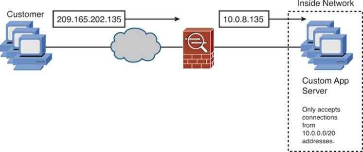
Figure 7-28. Outside NAT Scenario
Because the traffic arrives at the ASA with a public source IP address, but the application server will only accept connections from IP addresses in the 10.0.0.0/20 address space, you will need to perform static outside NAT on the incoming requests, before forwarding them to the application server.
To configure static outside NAT, navigate to Configuration > Firewall > NAT Rules and then click Add > Add Static NAT Rule. The Add Static NAT Rule dialog box will open, as shown in Figure 7-29, where you define a new static outside NAT rule.
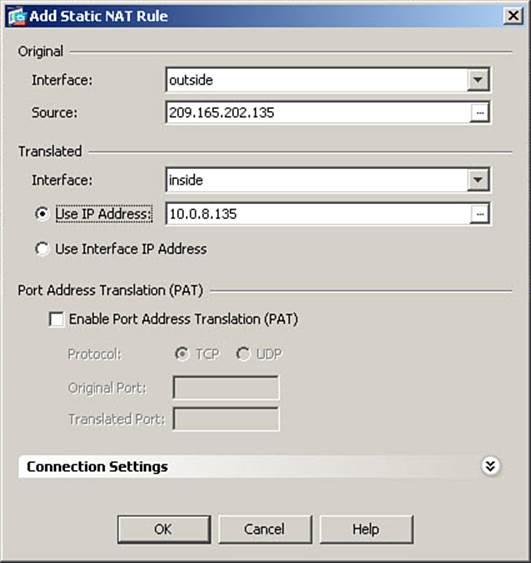
Figure 7-29. Configuring a Static Outside NAT Rule
In the Original area, you define the actual IP address(es) being translated, and the ingress interface for traffic arriving from such address(es). From the Interface drop-down list, select the ASA interface through which the host subject to translation is reached (where packets from said host willingress the ASA). Because this is outside NAT, the original interface will be the less secure interface in the traffic path. In Figure 7-29, the outside interface is selected.
In the Source field, enter the real IP address of the host(s) that will be translated. In Figure 7-29, the customer PAT address of 209.165.202.135 is entered.
In the Translated area, you define the address to which the host(s) will be translated when traffic from such host(s) egresses the ASA on a selected interface. In our example, we are creating a mapping for the customer traffic on the inside interface, so, in Figure 7-29, the inside interface is selected.
Click the Use IP Address radio button and enter the translated (mapped) IP address in the field. In Figure 7-29, the IP address of 10.0.8.135 is entered, which is an address we have allocated for use by this customer.
Note
Although not used in this example, it is perfectly permissible to use an IP address that overlaps the internal 10.0.0.0/24 network, such as 10.0.0.135, so long as you have ensured that address will never be allocated to an actual internal host. For instance, you might exclude a range of IP addresses from assignment by local DCHP, and use such a range for outside NAT assignments.
Click OK to accept the new static translation definition and close the Add Static NAT Rule dialog box. Then, click Apply to send the changes to the ASA.
The CLI command generated by the changes made follows:
static (outside,inside) 10.0.8.135 209.165.202.135 netmask 255.255.255.255 tcp 0
0 udp 0
If you are configuring the ASA from the CLI, you can enter this command directly in global configuration mode.
Note
The order in which interfaces and IP addresses are specified when using outside NAT is still real, mapped, mapped, real, just as in any other static command. Similarly, if you are using dynamic outside NAT (which is not recommended), the nat command would be bound to the less secure interface (outside in our example) and the global pool would exist on the more secure interface (inside in our example). The nat command must also include the keyword outside to indicate the use of outside NAT.
Other NAT Considerations
The performance of NAT was one of the principle functions of ASAs in most production networks. It is important to consider the ramifications that the changing of addresses has on other items in the ASA configuration. Several such items are discussed in this section.
DNS Rewrite (Also Known as DNS Doctoring)
Static inside NAT is normally performed for servers, so that external hosts, upon receiving the IP address of the server from an Internet-based DNS server, can route traffic to the server’s global IP address. Such traffic will arrive at the ASA and then be redirected to the internal server based on the interface and IP address in the static command.
However, what if the client is on the internal network? If you are using an internal DNS server, this presents no problems, as the local IP address of the server would be returned to the client performing a DNS query.
Figure 7-30 illustrates a network where internal clients make DNS queries to an external DNS server when looking for an internal server. This would present a problem, which the DNS Rewrite feature is designed to solve.
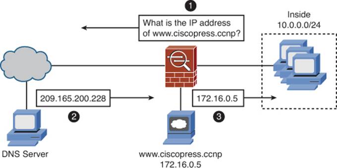
Figure 7-30. DNS Rewrite Scenario
The problem arises from the fact that the Internet-based DNS server does not know the private IP address of the server, or which DNS queries come from the same internal network as where the server is located. So, if client 10.0.0.103 were to send to the DNS server a DNS query looking for the server www.ciscopress.ccnp, the only address the server would know to respond with would be 209.165.200.228, the global IP address of the web server, as configured earlier. If the client were to attempt a connection to this address, it would be unsuccessful, as the server is actually located in the DMZ, but the global IP address would route through the outside interface.
Note
DNS Rewrite is supported for both static and dynamic NAT rules.
With DNS Rewrite enabled, the ASA inspects inbound DNS replies and, if the IP address being returned is a global IP address configured with a static inside NAT rule, translates the address inside the DNS reply to be the local IP address of the server. So, the 209.165.200.228 address embedded in the DNS reply would match the static inside NAT rule for the web server, and the ASA would translate this to the local IP address 172.16.0.5 before forwarding the reply to the requesting client. Client 10.0.0.103 would now attempt its connection to 172.16.0.5, which would be successful.
Note
DNS inspection must be enabled for DNS Rewrite to function.
To configure DNS Rewrite for hosts using static inside NAT translation, navigate to Configure > Firewall > NAT Rules. Click Add > Add Static NAT Rule if you are creating a new rule, or Edit > Edit Static NAT Rule if you are adding DNS Rewrite to an existing static translation rule. Click the expand symbol to the right of the words Connection Settings to make the DNS Rewrite option visible (it is hidden by default). Figure 7-31 shows an example of editing the static inside NAT rule previously configured for the web server. The Connection Settings area has already been expanded.
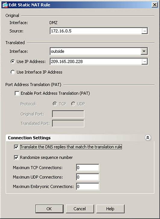
Figure 7-31. Configuring DNS Rewrite
Check the Translate the DNS Replies That Match the Translate Rule check box to enable DNS Rewrite for this static translation rule.
Click OK to accept the change and close the Add/Edit Static NAT Rule dialog box. Then click Apply to send the changes to the ASA.
The CLI commands generated by the changes made are as follows:
no static (DMZ,outside) 209.165.200.228 172.16.0.5 netmask 255.255.255.255
static (DMZ,outside) 209.165.200.228 172.16.0.5 netmask 255.255.255.255 dns tcp
0 0 udp 0
If you are configuring the ASA from the CLI, you can enter these commands directly in global configuration mode. The no command is generated because you are editing an existing rule.
Integrating NAT with ASA Access Control
Configuring NAT rules on an ASA impacts the configuration of access control rules, including interface access rules (interface ACLs), which filter traffic, user AAA rules (for Cut-through Proxy services), and Modular Policy Framework service policies (which can affect traffic handling in a number of ways), as they all typically refer to IP addresses that may be subject to translation.
In the case of interface ACLs, you must keep the following in mind:
• For inbound ACLs (applied to traffic as it ingresses the ASA through the interface), access rules are applied before NAT takes place. Therefore, an access control entry (ACE, a single line of an ACL) that filters source addresses must refer to the untranslated (original) address(es) of the source host(s). An access list that filters based on destination addresses must refer to the translated (mapped) address(es) of the destination host(s). This is true whether the traffic is moving from a higher-security interface to a lower-security interface (outbound flow) or vice versa (inbound flow).
Example 1: An ACL is applied inbound to the inside interface (more secure to less secure, or outbound connections). The source addresses referenced should be the local (untranslated) addresses. In our sample network, for example, you would permit or deny access from addresses in the 10.0.0.0/24 network.
Example 2: An ACL is applied inbound to the outside interface (less secure to more secure, or inbound connections). The destination addresses referenced should be the global (translated) addresses. In our sample network, for example, you would permit or deny access to the 209.165.200.228 address of the web server.
• For outbound ACLs (applied to traffic as it egresses the ASA through the interface), access rules are applied after NAT has taken place. Therefore, an ACE that filters source addresses must refer to the translated (global) address(es) of the source host(s). An access list that filters based on destination addresses must refer to the untranslated (original) address(es) of the destination host(s). This is true whether the traffic is moving from a higher-security interface to a lower-security interface (outbound flow) or vice versa (inbound flow).
Example 1: An ACL is applied outbound to the outside interface (outbound connections). The source addresses referenced should be the global (translated) addresses. In our sample network, for example, such a rule would apply whether traffic originated on the inside or the DMZ networks, as both would egress through the outside interface to reach the Internet. You would permit or deny access from addresses in the 209.165.200.224/27 address range, which was used for our translation examples.
Example 2: An ACL is applied outbound to the DMZ interface (which would be an inbound connection if originating on the outside interface, or an outbound connection if originating on the inside interface). The destination addresses referenced should be the local (untranslated) addresses of hosts on the DMZ. In our sample network, for example, you would permit or deny access to addresses in the 172.16.0.0/24 network.
Integrating NAT with MPF
If you apply Modular Policy Framework rules (discussed in Chapter 9, “Inspecting Traffic”) to traffic flows subject to NAT, similar rules apply. MPF rules, like access lists, can apply to traffic either as it ingresses the ASA through an interface or as it egresses the ASA through an interface.
In the case of MPF rules, the same rules apply as for interface ACLs:
• For rules applied to traffic as it ingresses an interface:
• The class flow specification must reference the untranslated IP address as the source IP address.
• The class flow specification must reference the translated IP address as the destination IP address.
• For rules applied to traffic as it egresses an interface:
• The class flow specification must reference the translated IP address as the source IP address.
• The class flow specification must reference the untranslated IP address as the destination IP address.
Integrating NAT with AAA (Cut-Through Proxy)
AAA (cut-through proxy) rules applied to an interface only affect traffic ingressing the ASA through that interface. The same rules for ingress traffic apply as those listed for MPF rules:
• The AAA rule must reference the untranslated IP address as the source IP address.
• The AAA rule must reference the translated IP address as the destination IP address.
Troubleshooting Address Translation
Troubleshooting NAT requires that you observe activity on the ASA itself while generating traffic to or from a host subject to translation rules. The most common commands used for this purpose are show xlate, show xlate detail, and clear xlate, which have all been examined already in this chapter. It also requires reviewing log messages generated by the address translation process (or access rules).
Improper Translation
If traffic does not appear to be translated according to a configured NAT rule you are expecting to perform the translation, you should consider performing the following steps in troubleshooting:
Step 1. Verify whether the traffic is being translated at all. Remember that if NAT control is enabled, and no translation rules are configured for a traffic flow, the traffic will be dropped. Use the show xlate or show xlate detail command to look for translations. Clear the translation table withclear xlate if recent changes have been made to translation rules.
Step 2. If traffic is not being translated, look for missing nat, global, or static commands, nat and global commands that do not have the same NAT ID number, or incorrect interface pairs configured within a static command.
Step 3. If traffic is being translated, but not by the correct NAT rule, check for overlapping translation rules. Keep in mind the order of precedence for NAT rules, from NAT bypass at the top to dynamic NAT at the bottom.
Protocols Incompatible with NAT or PAT
Some protocols encounter problems when running over NAT (and especially PAT). Ensure that any application traffic subject to translation rules on the ASA do not have the following features:
• Protocols that embed IP addresses at the application layer (within the data portion of packets, rather than the headers), unless the protocol is specifically supported by ASA packet inspection rules.
• Protocols that embed IP addresses at the application layer and use end-to-end encryption. If the payload of packets is encrypted when crossing through the ASA, even protocols supported by ASA packet inspection rules will not be properly translated.
• Protocols that include the IP or TCP/UDP headers as input to authentication hashing algorithms. These will not work with NAT or PAT, respectively, because NAT or PAT would be altering the headers subject to the integrity check. The AH protocol used within IPsec and authenticated BGP routing updates are examples of this.
In such cases, exempt application traffic using such protocols from NAT by using NAT bypass (preferred) or static identity NAT.
Proxy ARP
When address translation is configured on a Cisco ASA, the ASA performs proxy ARP for all global addresses in its translation table by default (note that this is for addresses in the translation table, not for addresses merely configured for NAT). In some cases, this is not desired because it might interfere with the proper operation of adjacent hosts.
You can disable proxy ARP behavior of the ASA on an interface by using the sysopt noproxyarp interface_name command in global configuration mode.
Caution
Extreme care should be taken before disabling proxy ARP on an ASA interface when NAT control is enabled. For example, if it were disabled on the outside interface, the ASA would not reply to ARP requests for any of the global IP addresses of internal servers subject to static inside NAT, and no hosts from the Internet would be able to initiate connections to any such servers.
NAT-Related Syslog Messages
Problems performing address translation will be logged by the ASA. These messages can assist you in narrowing your troubleshooting focus. One of the most common NAT-related syslog messages occurs when the ASA cannot create a translation slot because it was either unable to find a matching global pool (on the correct interface, with the correct pool number) or the pool addresses are exhausted.
The following syntax shows the system message 305005. This message is generated when a packet does not match any of the configured translation rules, while NAT control is enabled. The same message is used whether the session should have matched dynamic or static translation rules:
%PIX | ASA-3-305005: No translation group found for protocol src
interface_name:source_address/source_port dst
interface_name:dest_address/dest_port
The following syntax shows the system message 305006. There are several variations to this message, depending on which type of NAT rule and which protocol are involved. For instance, a static mapping “fails” if the ASA attempts to perform translation to an address that is a network identifier or broadcast address. A portmap failure indicates a problem applying PAT.
%PIX | ASA-3-305006: {outbound static | identity | portmap | regular)
translation creation failed for protocol src
interface_name:source_address/source_port
dst interface_name:dest_address/dest_port
Implementing NAT in ASA Software Versions 8.3 and Later
Beginning with software version 8.3, Cisco has radically altered the manner in which address translation is configured on an ASA. Software versions 8.2 and earlier used a style of NAT configuration that had existed for several years. This style of NAT configuration had the potential to be cumbersome to configure and difficult to keep organized, particularly with the introduction of new capabilities on the ASA, such as support for a much higher number of interfaces than previously supported, or configurations where all interfaces have the same security level. Thus, Cisco introduced a new, object-oriented configuration for NAT rules, which lessens complexity, reduces configuration size, and reduces the likelihood of configuration error.
Major Differences in NAT Beginning in Software Version 8.3
There are a large number of differences in how NAT is configured and processed in OS versions 8.3 and later versus OS versions 8.2 and before. A few of the major differences are covered in the following sections.
Network Objects
The implementation of NAT on an ASA running software version 8.3 or later is done through the use of network objects (hence, “object-oriented”). The concept of a network object is new in ASA software version 8.3. A network object differs from an object group (described in Chapter 8), because it defines a single IP address, range of addresses, network, or FQDN (although this option is fairly uncommon).
The host, range, or subnet that’s defined by a network object is used to identify the real, nontranslated, IP address in a NAT configuration. A network object can also be used to define any available translation addresses (similar to a global pool in versions 8.2 and earlier). You then refer to these objects in the NAT configuration.
By creating an object for each host, translated address, and service that is used in translation rules, it is easier to understand how the NAT configuration is being used, and “trace the logic” of the address translation that will be performed by the ASA. You can also configure complete translation definitions with one command, rather than having to link one or more nat commands to one or more global commands through the use of NAT ID numbers. The simplification of the NAT configuration and organization is the first step in the move toward “flow-based policies,” where a user configures what actions to apply to a flow (inspection, NAT, IPS, and so on) all in one place in the ASA configuration.
NAT Control
One significant change in NAT with software versions 8.3 and higher is that NAT control (enforcing use of NAT, as previously described in the section, “Enforcing NAT”) is no longer a supported option. If a connection finds no translation rules, it passes through the ASA without translation, as long as the connection is allowed by configured access rules and policies (including default behaviors).
Integrating NAT with Other ASA Functions
Perhaps the most significant change is that, when ACLs, MPF, AAA, Botnet Traffic Filter, and Web Cache Communications Protocol (WCCP) filters are applied to interfaces, they no longer need to refer to the translated addresses from NAT rules. All rules now refer to the network object by its native IP address or assigned identifier. Because a single host could have numerous translated addresses, depending on how many interfaces it communicated with, this radically reduces the complexity of configuration that was described in the section, “Other NAT Considerations,” and its discussion of integrating NAT with these other functions.
NAT “Direction”
The security levels of interfaces no longer matter in the configuration of NAT rules. For example, there is no longer a concept of “outside NAT” versus “inside NAT.” All NAT rules are configured the same way, regardless of whether the source is on a higher security or lower security interface than the destination.
NAT Rule Priority
NAT rules are now configured in an object-oriented manner instead of all being configured globally, so the NAT rule priority scheme for versions 8.2 and earlier (covered in the section, “NAT Rule Priority”) no longer applies. Versions 8.3 and later now have a different structure for determining which NAT rule is applied to an address(es) in a packet. This is covered in the section, “NAT Table,” later in this chapter.
New NAT Options in OS Versions 8.3 and Later
There is now an any option that can be used when defining ingress and egress interfaces in the NAT configuration. This enables the creation of single-line translation rules that will apply to all interfaces, rather than one or more lines of configuration for each interface where a host required translation, resulting in more compact and user-friendly configurations.
You can configure translations as part of network object definitions, which are added to the configuration. This is known as “auto NAT” and is described in the section, “Configuring Auto (Object) NAT.” Auto NAT reduces configuration complexity when only one translation policy is required for a host.
You can configure a single NAT rule that will translate both the source and destination addresses in a packet. This is known as manual NAT or “twice NAT,” because NAT can be performed twice—once on the source IP and once on the destination IP. Although all manual NAT rules are thus twice NAT rules, the term “twice NAT” is more commonly used only if translations actually occur to both source and destination addresses.
Starting in OS version 8.3, it is now possible to configure a static translation for many-to-one translation (PAT).
You can group translation network objects (address pools) into an object group (object groups are fully covered in Chapter 8), and use that object group in creating translation rules.
NAT rules can be defined as unidirectional, meaning only traffic sourced from a defined object can use the translation. Connections toward the object must match a different NAT rule, or they will not be translated.
NAT Table
As discussed earlier in the section, “NAT Rule Priority,” OS versions 8.2 and earlier implemented various NAT rules in a structured order of operations that depended on what type of NAT rules existed in the configuration, with each having its own priority. Because several types of NAT rules could apply to the same source host, this leads to complexity, and frequently leads to troubleshooting scenarios where translation is being applied differently than the administrator intended.
Beginning in OS version 8.3, NAT rules are placed in a NAT Table, which has three sections. NAT rules are searched from top to bottom in the NAT Table, and the first rule that matches the packet being analyzed is always applied, regardless of whether it is a static or dynamic rule, a translation exemption, or whether the source is on a higher or lower security interface than the destination. This reduces the complexity of NAT configuration and troubleshooting. The sections in the NAT Table are as follows:
• Manual NAT (1st section): Default location for manual NAT statements.
• Auto NAT (2nd section): Also referred to as “object NAT” because the contents of this section come from NAT rules configured within network object definitions. This is the default location for auto NAT statements.
• Manual NAT After Auto NAT (3rd section): Manual NAT entries created using the after-auto keyword are located here.
The Manual NAT section allows an administrator to define translation rules to be compared before the remaining sections. These rules are usually very specific. For example, a rule could translate both source and destination addresses in a packet, which would require the packet to be addressed from a specific source to a specific destination in order to match the rule. This example is similar in function to the policy NAT rules created in OS versions 8.2 and earlier. You can also add entries to this section if a host requires multiple translation rules, which depend on the input or output interfaces or the destination address. For example, a server on the inside interface that retains its original address when communicating with the DMZ interface, but gets statically translated to a globally routable IP when communicating with the outside interface.
The Auto NAT section, also referred to as object NAT, contains translation rules defined as part of the network object definition itself. This allows each object definition to contain a single translation only. For example, a server allowing Internet-based clients to connect might contain a single static translation rule, or an inside network segment containing only clients might contain a single dynamic NAT or PAT rule, to allow connections to be initiated by the clients defined in the object.
The Manual NAT After Auto NAT section contains translation rules that could conflict with the entries in the prior two sections. These entries are configured the same way as other manual NAT rules (but are generally less specific) but are specified for use only after auto NAT. These translations are therefore used only if a packet does not match any translation rules from the first two sections of the NAT Table.
Example 7-5 shows a NAT Table displayed by using the show nat command on a newly rebooted ASA (as indicated by the 0 hit counts for all rules). It is inserted here for reference. The configuration that leads to this NAT Table is the subject of the next several sections. There is also a detailed variation of the command show nat detail.
Example 7-5. NAT Table Displayed
FIREWALL# show nat
Manual NAT Policies (Section 1)
1 (inside) to (outside) source dynamic INSIDE-SEGMENT VENDOR-SERVER-PAT
destination static VENDOR-SERVER VENDOR-SERVER service HTTPS VENDOR-PORTMAP
translate_hits = 0, untranslate_hits = 0
2 (inside) to (outside) source static INSIDE-SEGMENT INSIDE-SEGMENT destination
static SATELLITE-OFFICE SATELLITE-OFFICE
translate_hits = 0, untranslate_hits = 0
3 (inside) to (outside) source static INSIDE-SEGMENT PARTNER-VPN-NAT-OUTBOUND
destination static PARTNER-VPN-SEGMENT PARTNER-VPN-NAT-INBOUND
translate_hits = 0, untranslate_hits = 0
Auto NAT Policies (Section 2)
1 (DMZ) to (outside) source static DMZ-WEB-PRIV DMZ-WEB-PUB
translate_hits = 0, untranslate_hits = 0
2 (DMZ) to (outside) source static DMZ-FTP-PRIV DMZ-FTP-PUB
translate_hits = 0, untranslate_hits = 0
3 (DMZ) to (outside) source static DMZ-HTTPS-PRIV DMZ-PAT-OUTSIDE service tcp
8443 https
translate_hits = 0, untranslate_hits = 0
4 (DMZ) to (outside) source static DMZ-SMTP-PRIV DMZ-PAT-OUTSIDE service tcp
smtp smtp
translate_hits = 0, untranslate_hits = 0
5 (any) to (outside) source dynamic INSIDE-SEGMENT OUTSIDE-NAT-POOL interface
translate_hits = 0, untranslate_hits = 0
6 (any) to (DMZ) source dynamic IT-SEGMENT 172.16.0.254
translate_hits = 0, untranslate_hits = 0
Manual NAT Policies (Section 3)
1 (any) to (outside) source dynamic IT-SEGMENT IT-OUTSIDE-PAT
translate_hits = 0, untranslate_hits = 0
This method of matching a NAT rule might at first seem like it would have more overhead than that implemented in previous OS versions; however, it allows for more flexibility, for example, the any option for both input and output interfaces. Because traffic can match a rule no matter which interface it ingresses, the order of entries in the NAT Table becomes very important. The NAT Table must therefore be structured much like an ACL, with more specific entries at the top, and less specific entries at the bottom. Note that all entries are assigned a sequence number, per section of the NAT Table. Use this sequence number to ensure that NAT rules are applied in the order you intend.
Configuring Auto (Object) NAT
Auto NAT is the simplest form of NAT to configure on the ASA. With auto NAT, the NAT rule is configured in the same ASDM window as that used to create the object itself. Any single object can have only one auto NAT rule associated with it. The direction of any translation is defined by selecting the source object and the input (ingress) and output (egress) interfaces. The use of the any keyword for interface adds a broader scope to a translation definition.
Auto NAT allows for the definition of three basic NAT configurations for a network object:
• Static NAT: Creates a one-to-one translation for the object, which will never change. Similar to static NAT in previous OS versions, this type of rule creates a permanent entry in the NAT Table and allows for flows to be initiated in either direction (with the object as source or destination), as long as the initial packets in the flow are permitted by access policies on the ASA.
• Dynamic NAT: Creates a one-to-one translation for the object, but the NAT Table entry is created only after the host initiates a flow that matches the policy. This is similar to dynamic NAT in previous OS versions and allows the possibility for multiple hosts to reuse translated addresses. Dynamic NAT is typically configured when there are not enough translated addresses available to provide for one-to-one translations, but PAT is not used, either to conserve NAT Table entries (because PAT creates a translation entry for each individual flow that is translated, rather than one per source IP address) or because applications are in use that are incompatible with PAT. After a temporary translation entry is created by the host that initiated a connection, that translation can be used in both directions, as long as allowed by access policies. This is the same as the use of dynamic PAT in previous OS versions.
• Dynamic PAT: A many-to-one translation that allows multiple original addresses to simultaneously share one or more translated addresses. Although this provides for maximum conservation of globally routable IP addresses, it actually creates more translation entries in the NAT Table than dynamic NAT, as already mentioned, and is not compatible with all applications. Many common applications, such as FTP and SQLnet, are incompatible with PAT.
Note
The translation rules created in the following sections are not intended to convey “best practice” at all times. In many instances, the scenarios used are purposely chosen to be able to demonstrate various available options.
Configuring Static Translations Using Auto NAT
The configuration scenario used in this section will be the same as that used in the earlier section, “Configuring Static Inside NAT”—two application servers exist on the DMZ interface that require access from the Internet. A web server with native IP address 172.16.0.5 and an FTP server with native IP address 172.16.0.10. The web server will use translated IP address 209.165.200.228 when communicating with the outside interface (the Internet), and the FTP server will use translated IP address 209.165.200.229. If desired, you can refer to Figure 7-16 for a graphical representation of the network diagram.
To begin the process, navigate to Configuration > Firewall > Objects > Network Objects/Groups to open the Network Objects window. Then, from the Add drop-down menu, select Network Object to create a new network object. The Add Network Object window opens, as shown inFigure 7-32, where you define a new network object and the associated auto NAT rule.
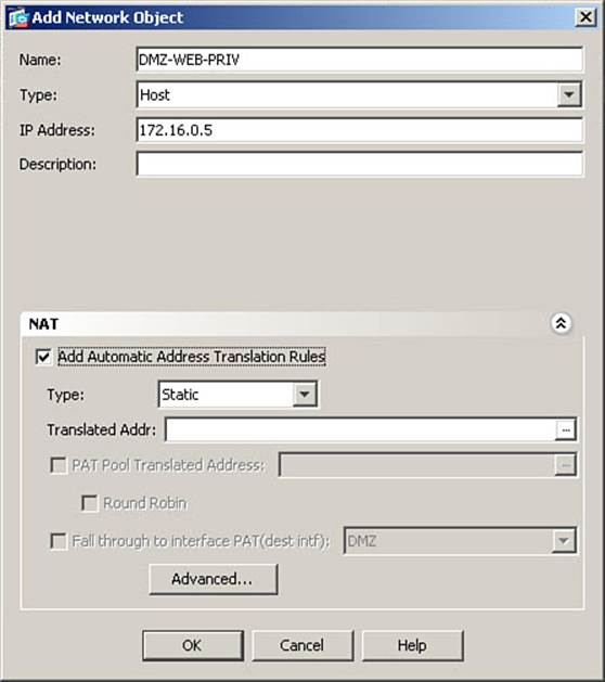
Figure 7-32. Configuring a (Host) Network Object and Associated Static NAT Rule
In the top part of this window, you define the network object (in this case, an individual host, and its original, non-translated, IP address).
In the Name field, enter the name to be used to refer to this network object. Remember that this name will be used in ACLs, MPF policies, and so on to refer to this object, so it should be short, yet adequately descriptive. In Figure 7-32, DMZ-WEB-PRIV is entered, which clearly defines the web server on the DMZ, private address.
Note
If your organization does not have a clearly defined naming convention, you may want to create one. As an alternative, you can give network objects names that include the native IP address, such as OBJ-172.16.0.5.
In the Type field, you define the type of object being created. In this case, select Host. The available choices are Host, Range, Network, or FQDN.
In the IP Address field, enter the original (native) IP address used by this object. In Figure 7-32, the IP address of 172.16.0.5 is entered.
You may optionally enter a description in the Description field. In our example, this is left blank.
If you were creating a network object with no NAT rules, you would be done at this point and would click OK to accept the new object definition and close the Add Network Object window. In this scenario, however, you want to create a static NAT entry for this host, as part of the network object definition. Therefore, expand the NAT portion of the window. It is shown expanded in Figure 7-32.
To create an auto NAT rule, rather than a manual NAT rule, check the Add Automatic Address Translation Rules box, and then select a translation type. In Figure 7-32, Static is selected as the translation type.
Because you will need to create a new network object for the translated address in this scenario, click the ellipsis (...) button to the right of the Translated Addr field to open the Browse Translated Addr window, as shown in Figure 7-33.
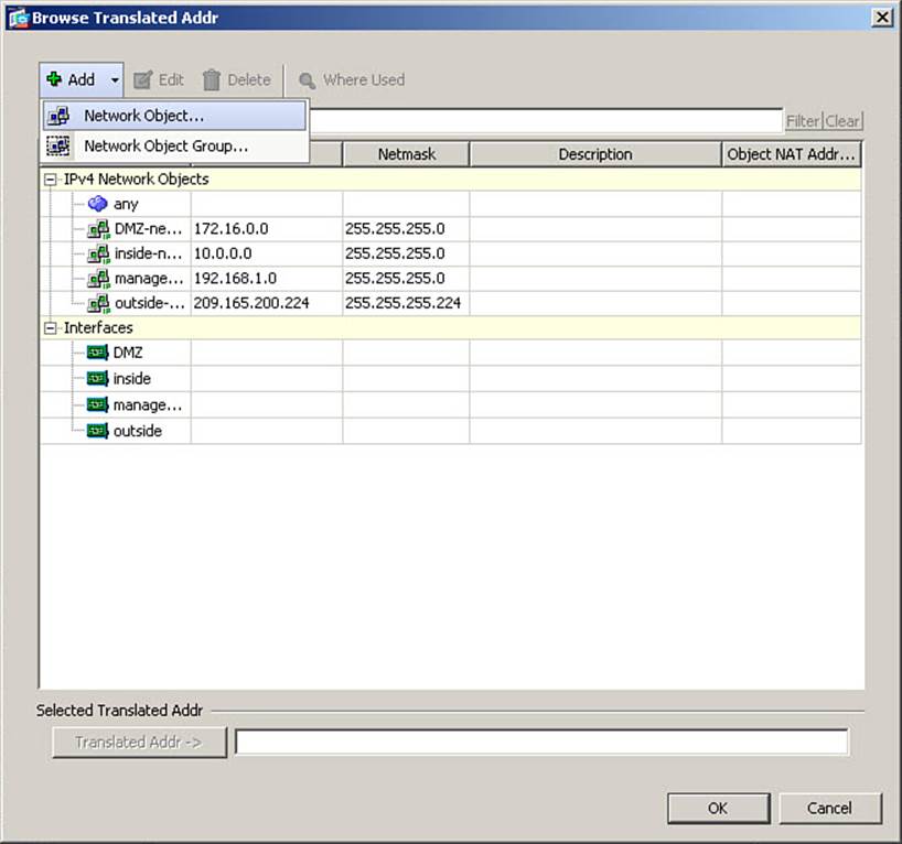
Figure 7-33. Creating a New (Host) Translation Network Object
This window functions much as the Network Objects window, so to add a translation network object, from the Add drop-down menu, select Network Object (as shown in the figure) to open the Add Network Object window once again, as shown in Figure 7-34.
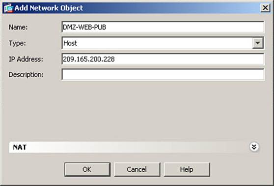
Figure 7-34. Configuring a Translation Network Object
Note
It is possible to create translation rules simply by typing a translated address into the Translated Addr field, but to maximize flexibility and fully demonstrate an object-oriented example, this chapter shows the creation of translation network objects.
This time, you will define a network object for the translated address, so enter the appropriate information for the translated object definition. Remembering that in our scenario, this translation will be used for communication through the outside interface. (In Figure 7-33, DMZ-WEB-PUB is entered in the Name field.) Because this is a host-specific static translation, Host is selected as the Type.
Note
FQDN is not an available option when creating a translation network object. This is because, although not all network objects have translation components and therefore an FQDN type is valid, a translation network object must by definition, reference an address (or range of addresses), and an FQDN is not a valid choice for this function.
Finally, in the IP Address field, 209.165.200.228 is entered. Click OK to complete the creation of the translation network object and return to the Browse Translated Addr window, as shown in Figure 7-35. The newly created translation object appears in the list of IPv4 network objects and is highlighted, but it has not yet been assigned as the translated address.
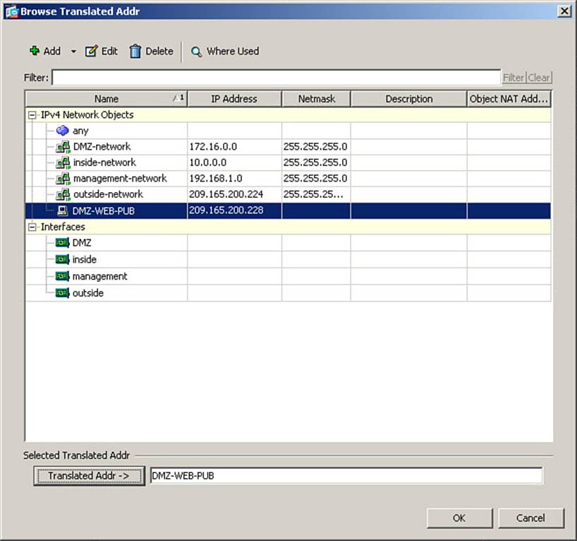
Figure 7-35. Assigning a Translated Addr Network Object
To assign this new object as the translated address for the original network object being created, while the translation object is highlighted, click the Translated Addr button at the bottom of this window (as done in Figure 7-35). Then, click OK to complete the assignment and return to the original network object definition window. The Translated Addr field is now populated with information for the translation object just created (shown on the left side of Figure 7-36).
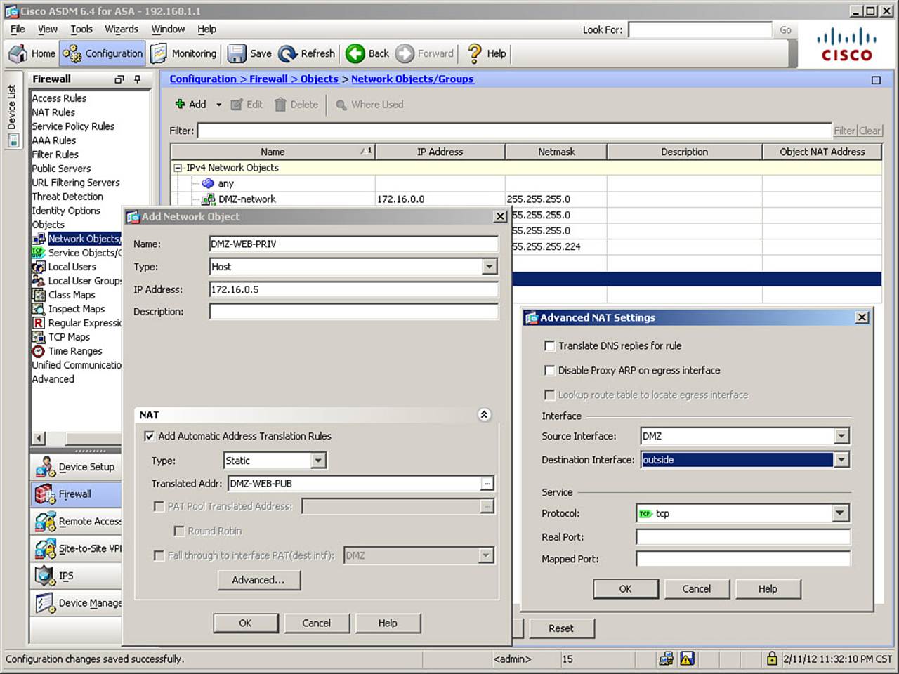
Figure 7-36. Completing the Creation of a New Network Object
You’re almost finished. Because this particular translation is intended to occur only between a specific pair of interfaces (DMZ and outside, in this case), it is necessary to define the “direction” of this translation rule. To do so, click the Advanced... button at the bottom of the Add Network Object window. This opens the Advanced NAT Settings window, as shown on the right side of Figure 7-36.
In the Interface section of this window, you have the ability to choose a source and destination interface. Both are set to “any” by default. The source interface should be set to the actual location of the host for which this translation is being created (in our case, DMZ, which is selected inFigure 7-36). The destination interface should be set to any interface where the host in question will be referred to by the translated address (in our case, outside, which is selected in Figure 7-36).
After setting the interface choices, click OK to complete the settings of Advanced NAT Settings. Then, click OK again to complete the definition of the new network object for the DMZ web server.
Follow the same procedure to create a network object for the DMZ FTP server, using appropriate information. Then, click Apply to send the changes to the ASA.
The CLI commands generated by the changes made are as follows (spacing inserted for readability):
object network DMZ-FTP-PRIV
host 172.16.0.10
!
object network DMZ-FTP-PUB
host 209.165.200.229
!
object network DMZ-WEB-PRIV
host 172.16.0.5
!
object network DMZ-WEB-PUB
host 209.165.200.228
!
object network DMZ-FTP-PRIV
nat (DMZ,outside) static DMZ-FTP-PUB
!
object network DMZ-WEB-PRIV
nat (DMZ,outside) static DMZ-WEB-PUB
If you are configuring the ASA from the CLI, you can enter these commands directly in global configuration mode.
If using ASDM, the definition of the network object will be split into two parts: one defining the host address and a separate one defining the NAT rule. The reason for this is that, although there will only be one network object defined for a host—for example, DMZ-WEB-PRIV—there may be multiple translation rules applied to that host (for example, the static just created, a NAT exemption for communicating across a VPN, and so on). All such translation rules will be grouped together under the object in the section of the configuration showing translation rules, which makes it easier to examine all the rules to which a host is subject.
It is not necessary to split the definition this way if configuring from the CLI; however, it is necessary to create the translation objects first, so that you can use their names when configuring the NAT rule for the original network object, as shown here:
object network DMZ-FTP-PUB
host 209.165.200.229
!
object network DMZ-FTP-PRIV
host 172.16.0.10
nat (DMZ,outside) static DMZ-FTP-PUB
!
object network DMZ-WEB-PUB
host 209.165.200.228
!
object network DMZ-WEB-PRIV
host 172.16.0.5
nat (DMZ,outside) static DMZ-WEB-PUB
Configuring Static Port Translations Using Auto NAT
You can use auto NAT to configure static port translations, similar to what was called static inside PAT in OS versions 8.2 and before. To demonstrate this, we once again use a previously demonstrated example. If desired, refer to Figure 7-20 for a graphical depiction of the network diagram.
In this scenario, you have two servers located on the DMZ segment. The first, with a native IP address of 172.16.0.15, hosts a secure web-based application and listens for HTTPS connections on customized TCP port 8443. The second is a mail server, with a native IP address of 172.16.0.20, and listens for SMTP connections on the standard TCP port 25. You have only one global IP address available for use: 209.165.200.230.
Using the same methods just demonstrated, create network object definitions for the HTTPS and SMTP servers. Also, create a translation network object named DMZ-PAT-OUTSIDE, using the 209.165.200.230 address.
To configure static port translations for the two servers, it is necessary to edit the Advanced NAT Settings for each of these objects. To do so, navigate to Configuration > Firewall > Objects > Network Objects/Groups to open the Network Objects window. Select one of the new server objects (this scenario will show the HTTPS server), and click the Edit button at the top of the window to open the Edit Network Object window. Click the Advanced... button at the bottom of this window to open the Advanced NAT Settings window. Figure 7-37 shows this sequence.
Figure 7-37. Configuring a Static Port Translation
In the interfaces section of this window, select the Source and Destination interfaces of DMZ and outside, respectively, as before, because this static port translation is unique to that interface pair. Figure 7-37 shows these selections.
Static port translations are created in the Service section of the Advanced NAT Settings window. The default protocol setting is TCP, which is what this scenario requires. In the Real Port field, enter the port that the server is natively configured to listen on (in this case, 8443). In the Mapped Port field, enter the port that connections will be made to on the Destination interface (in this case, 443). Figure 7-37 shows these settings.
Click OK to accept the changes and close the Advanced NAT Settings window. Click OK again to do the same in the Edit Network Object window. Repeat this procedure for the SMTP server—this time setting both the real port and mapped port to a value of 25. Then, click Apply to send the changes to the ASA.
The CLI commands generated by the changes made are as follows (spacing inserted for readability):
object network DMZ-HTTPS-PRIV
host 172.16.0.15
!
object network DMZ-PAT-OUTSIDE
host 209.165.200.230
!
object network DMZ-SMTP-PRIV
host 172.16.0.20
!
object network DMZ-HTTPS-PRIV
nat (DMZ,outside) static DMZ-PAT-OUTSIDE service tcp 8443 443
!
object network DMZ-SMTP-PRIV
nat (DMZ,outside) static DMZ-PAT-OUTSIDE service tcp 25 25
If you are configuring the ASA from the CLI, you can enter these commands in global configuration mode.
Examine the following CLI commands to understand the structure:
object network DMZ-HTTPS-PRIV
nat (DMZ,outside) static DMZ-PAT-OUTSIDE service tcp 8443 443
In the nat command, the interface names are listed as original first, and then translated. The word static defines the translation type. The translated address is then defined (in this case, DMZ-PAT-OUTSIDE). The keyword service is new and indicates that the ASA is to perform static port translation. Finally, the ports are listed in the order real (actually configured on the server), and then mapped (translated). These two port numbers can be the same, as they are for the SMTP server, or different, as they are for the HTTPS server.
Comparing Static NAT Configurations from OS Versions 8.2 and 8.3

From the preceding examples, it might not be immediately apparent how the method of defining translations in OS versions 8.3 and later reduces the size of the configuration when compared to a similar configuration in OS versions 8.2 and earlier, as claimed. This is because of the simplistic examples, where each server object has had only one translation rule associated with it. Consider the following example, where a server on the inside interface is statically translated to another address on an ASA with seven interfaces (inside, outside, DMZ, and four other interfaces). The translated address used is the same on all interfaces, which makes it possible to use the “any” interface option on the 8.3 ASA. Example 7-6 shows the version 8.2 configuration, and Example 7-7 shows the corresponding 8.3 configuration that accomplishes the same translations.
Example 7-6. Sample Static Configuration from OS Version 8.2
static (inside,outside) 209.165.200.231 10.0.0.10
static (inside, DMZ) 209.165.200.231 10.0.0.10
static (inside, INTF4) 209.165.200.231 10.0.0.10
static (inside, INTF5) 209.165.200.231 10.0.0.10
static (inside, INTF6) 209.165.200.231 10.0.0.10
static (inside, INTF7) 209.165.200.231 10.0.0.10
Example 7-7. Sample Static Configuration from OS Version 8.3
object network INSIDE-SVR-PUB
host 209.165.200.231
object network INSIDE-SVR-PRIV
host 10.0.0.10
nat (inside,any) static INSIDE-SVR-PUB
As the examples demonstrate, the translations are configured with a single line. Even the total number of configuration lines is reduced, despite first creating the two network objects.
Configuring Dynamic Translations Using Auto NAT
Creating dynamic translations with auto NAT is done using the same ASDM screens as static translations. One important difference in functionality, however, is that while static translations never expire, translation slots created by a dynamic NAT rule expire after being idle for 3 hours, by default (not seeing any traffic that uses the translation slot). The presented scenario will once again use a familiar example (with a slight modification) to begin. You will configure a dynamic translation for the inside network, 10.0.0.0/24, to a range of translated addresses, 209.165.200.235–254, for use on the outside interface. These translations will be one-to-one (NAT, not PAT). If this pool of addresses is exhausted, you want to “back up” this translation range by using PAT with the interface address of the ASA acting as the PAT translation address. If desired, refer to Figure 7-5 for a graphic representation of the network diagram. In pre-8.3 versions of the OS, this was done with the following configuration:
nat (inside) 1 10.0.0.0 255.255.255.0
global (outside) 1 209.165.200.235-209.165.200.254 netmask 255.255.255.224
global (outside) 1 interface
Remember that the concept of NAT ID numbers no longer exists. It is not necessary in OS versions 8.3 and later to map the nat and global commands together.
To begin the process, navigate to Configuration > Firewall > Objects > Network Objects/Groups to open the Network Objects window. Then, from the Add drop-down menu, select Network Object to create a new network object. The Add Network Object window opens, as shown inFigure 7-38.
Figure 7-38. Configuring a (Network) Network Object and Associated Dynamic NAT Rule
In Figure 7-38, INSIDE-SEGMENT is entered in the Name field, because it is short, yet adequately descriptive of the original network object to be created. In the Type field, Network is selected.
Note
When Network is selected as the object type, a Netmask field is added to the window. This is shown is Figure 7-38. If you refer to Figure 7-32, where a host object was defined, there was no Netmask field.
In the IP Address field, enter the original (native) IP address of this object. In Figure 7-38, the IP address of 10.0.0.0 is entered. In the Netmask field, enter the appropriate netmask value or select one from the drop-down list. In this case, 255.255.255.0 is selected from the drop-down list.
Expand the NAT portion of the window. It is shown expanded in Figure 7-38. Check the Add Automatic Address Translation Rules box, and then select a translation type. In Figure 7-38, dynamic is selected as the translation type.
Because you will need to create a new network object for the translated address in this scenario, click the ellipsis (...) button to the right of the Translated Addr field to open the Browse Translated Addr window. From the Add drop-down menu, select Network Object to open the Add Network Object window once again, as shown in Figure 7-39.
Figure 7-39. Configuring a New (Range) Translation Network Object
In the Name field, enter a name for the object to be created. In Figure 7-39, OUTSIDE-NAT-POOL is entered. Select Range as the Type. Doing this alters the appearance of the window to show fields of Start Address and End Address. This has already been done in Figure 7-39.
Note
A name is optional for some translation objects, but required for others. This can be seen by observing how the Add Network Object window changes depending on your selections. For example, the label for the Name field is Name (optional): in many cases, but depending on selections (such as selecting a Type of Range), the label will change to Name:, indicating it is a required field.
In the Start Address and End Address fields, enter the first and last addresses in the pool range. In Figure 7-39, 209.165.200.235 and 209.165.200.254 are entered, respectively.
Using the same procedures as already demonstrated, assign this object as the Translated Addr for the INSIDE-SEGMENT object being created and return to the Add Network Object window, as shown in Figure 7-40.
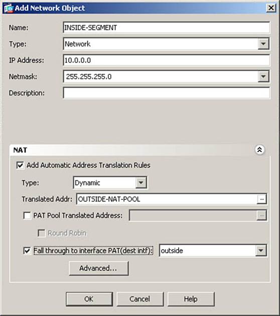
Figure 7-40. Configuring Interface PAT to Back Up a NAT Pool
At the bottom of this window, check the Fall Through to Interface PAT (Dest Intf) button and select the outside interface from the drop-down list. Doing this also sets the outside interface as the destination interface for this rule, as if you had entered the Advanced NAT Settings window and made such a change. Finally, click OK to complete the creation of the new Network Object.
Note
Although it might seem necessary to go to the Advanced NAT Settings window and select inside as the source interface, this is not the case. In this scenario, source addresses of 10.0.0.0/24 exist through only one interface; however, leaving the source interface setting at the default ofany provides great flexibility. An example of this is shown in the section, “Comparing Dynamic NAT Configurations from OS versions 8.2 and 8.3.”
To demonstrate an example of the use of PAT only (also referred to as “PAT Hide”), we will continue the scenario as follows: You will create a network object named IT-SEGMENT, using address 10.0.1.0/24.
You will then create a PAT translation rule for communication from the IT-SEGMENT object to the DMZ network using the address 172.16.0.254 as the translated address.
Note
Because there is no concept of NAT control is OS versions 8.3 and later, this is not necessary in the sample network to get traffic through the firewall. The scenario assumes the existence of software firewalls on the DMZ servers, which allow connectivity only from the PAT address, 172.16.0.254. Also, you have not configured the ASA to be able to route to the 10.0.1.0/24 subnet. Therefore, this scenario continuation is primarily for purposes of illustration.
Using procedures already demonstrated, create the IT-SEGMENT object, assigning the appropriate name, type, and address. Figure 7-41 shows a partially configured Add Network Object window.
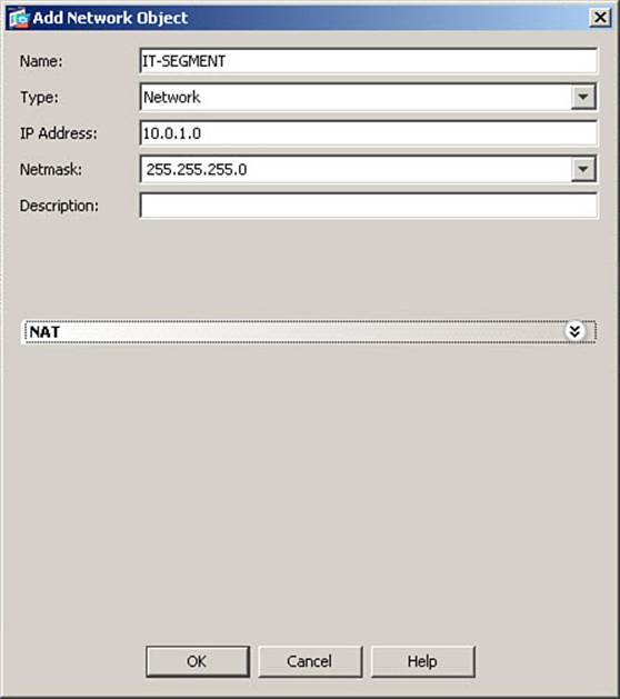
Figure 7-41. Partially Configured Network Object
Expand the NAT section of this window and check the box to enable auto NAT, as shown in Figure 7-42.
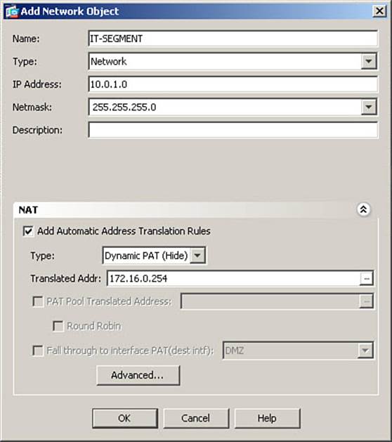
Figure 7-42. Configuring a Static PAT Rule
Select Dynamic PAT (Hide) in the Type field, as shown in Figure 7-42. Then, in the Translated Addr field, directly enter the PAT address. Figure 7-42 shows the scenario PAT address of 172.16.0.254. Using procedures already described, enter the Advanced NAT Settings window and set the Destination interface to DMZ. Click OK to accept this change and return to the Add Network Object window. Then, click OK to complete the creation of the new object and translation rule. Finally, click Apply to send the changes to the ASA.
The CLI commands generated by the changes made are as follows. Note the new options demonstrated here, of defining both a range and a subnet, rather than only a host address as network objects (spacing inserted for readability):
object network INSIDE-SEGMENT
subnet 10.0.0.0 255.255.255.0
!
object network IT-SEGMENT
subnet 10.0.1.0 255.255.255.0
!
object network OUTSIDE-NAT-POOL
range 209.165.200.235 209.165.200.254
!
object network INSIDE-SEGMENT
nat (any,outside) dynamic OUTSIDE-NAT-POOL interface
!
object network IT-SEGMENT
nat (any,DMZ) dynamic 172.16.0.254
If you are configuring the ASA from the CLI, you can enter these commands in global configuration mode.
Using Object Groups in NAT Rules
The creation and use of object groups is covered in Chapter 8. However, it is not necessary to understand all the options available with object groups to understand how they can be used in NAT rules.
Recall the scenario just covered in the section, “Configuring Dynamic Translations Using Auto NAT.” You configured the INSIDE-SEGMENT network object to use first a pool of addresses using NAT, then to fall back on a single PAT address, if these NAT addresses were all in use. For this topic, we extend that scenario as follows: Following rapid growth of your organization, you determine that the pool of NAT addresses is not large enough to accommodate your needs. Furthermore, because of the use of some applications incompatible with PAT, you need more addresses available for NAT. You therefore obtain from your ISP a second block of addresses for your use: 209.165.201.0/27. You want to assign 20 of these addresses into a pool for use with NAT, and one address as a PAT fallback, prior to the use of the ASA interface address for PAT.
You are attempting to configure the following:
1. Hosts in the INSIDE-SEGMENT object will first use the NAT pool addresses of 209.165.200.235-254. These will be assigned in a seemingly random manner, based on an internal ASA algorithm, until all are in use.
2. You want hosts in the INSIDE-SEGMENT object to use addresses in a new range, 209.165.201.10-29, assigned in the same manner.
3. If both these pools are fully utilized, you want further connections from INSIDE-SEGMENT hosts to use PAT, utilizing the address 209.165.201.30.
4. In the unlikely scenario that the previous PAT address has all ports utilized, you want remaining connections from INSIDE-SEGMENT hosts to use PAT, utilizing the ASA’s interface address.
Using procedures already demonstrated, you need to create new network objects, as follows:
1. An object OUTSIDE-NAT-POOL2, defined as the range 209.165.201.10-29
2. An object OUTSIDE-PAT, defined as the host address 209.165.201.30
To refer to the combination of all these addresses as a single logical pool to be used for translation, you must create a network object group. To begin the process, navigate to Configuration > Firewall > Objects > Network Objects/Groups to open the Network Objects window. Then, from the Add drop-down menu, select Network Object Group to create a new network object group. The Add Network Object Group window opens, as shown in Figure 7-43.
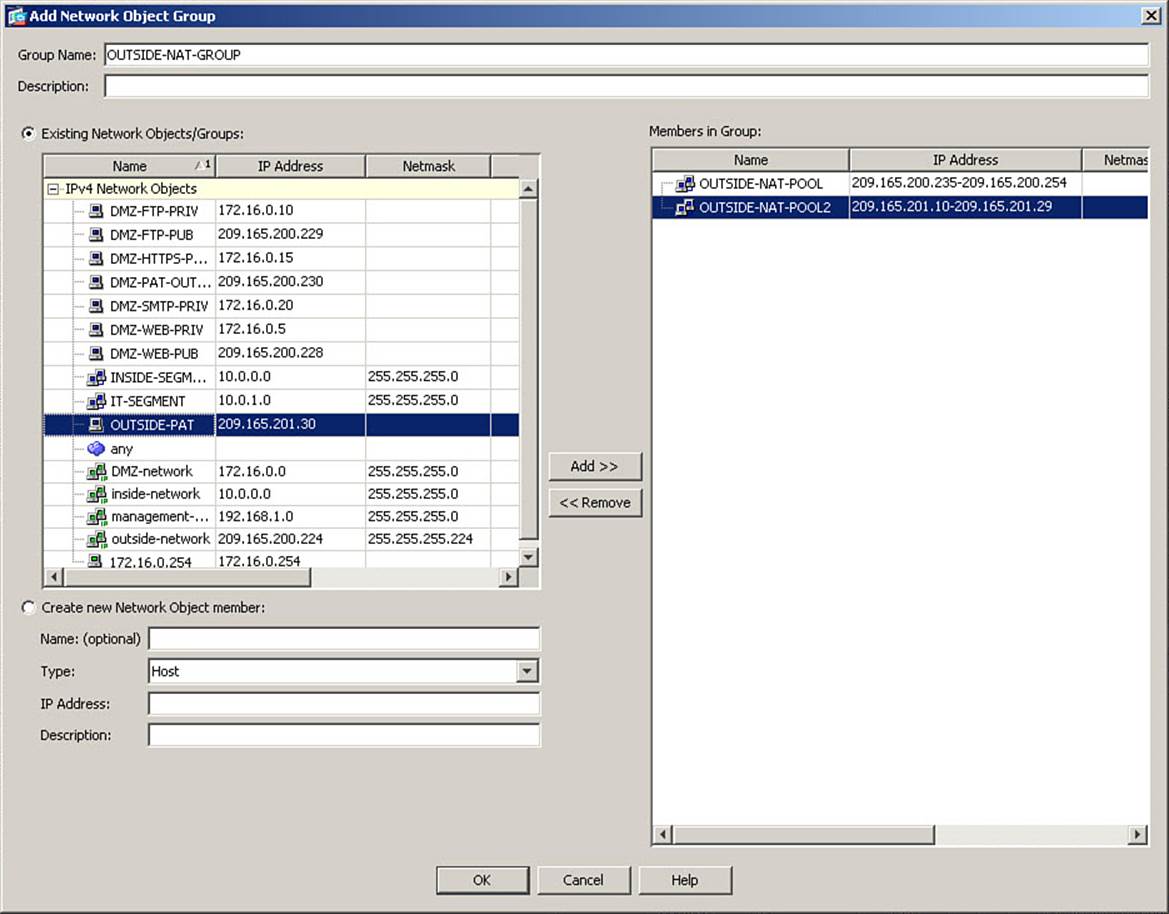
Figure 7-43. Configuring a Network Object Group
In the Group Name field, enter a brief but descriptive name for this group. In Figure 7-43, OUTSIDE-NAT-GROUP is entered. Then, in the Existing Network Objects/Groups list, select the three network objects that will comprise this group, and click the Add >> button to move their names to the Members in Group list. Figure 7-43 shows the two NAT pools already added, and the PAT object name selected, to demonstrate what the process looks like.
After you add all desired members to the group, click OK to complete the creation of the new object group.
Next, select the INSIDE-SEGMENT network object and click the Edit button to open the Edit Network Object window, as shown in Figure 7-44.
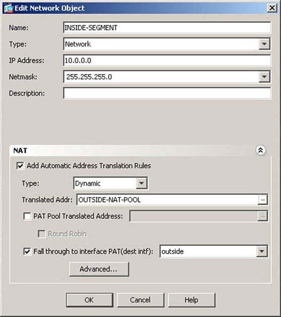
Figure 7-44. Editing a Network Object
In the NAT portion of the window, you see the previously configured value of OUTSIDE-NAT-POOL in the Translated Addr field. Click the ellipsis (...) button to the right of this field to open the Browse Translated Addr window, as shown in Figure 7-45.
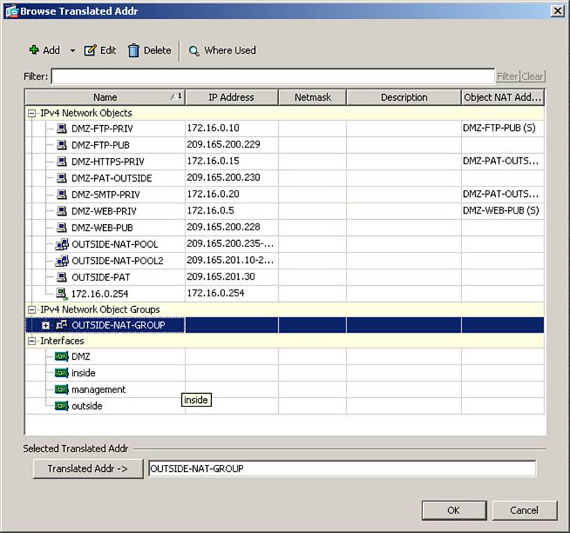
Figure 7-45. Assigning an Object Group as a Translated Addr
Select the newly created object group, and click the Translated Addr -> button at the bottom of the window to change the assignment of translated addresses for the object. Figure 7-45 shows this completed. Then, click OK to complete this assignment.
Verify that the object group name now appears in the Translated Addr field, and click OK to complete the editing of the network object. Finally, click Apply to send the changes to the ASA.
The CLI commands generated by the changes made are as follows (spacing inserted for readability):
object network OUTSIDE-NAT-POOL2
range 209.165.201.10 209.165.201.29
!
object network OUTSIDE-PAT
host 209.165.201.30
!
object-group network OUTSIDE-NAT-GROUP
network-object object OUTSIDE-NAT-POOL
network-object object OUTSIDE-NAT-POOL2
network-object object OUTSIDE-PAT
!
object network INSIDE-SEGMENT
nat (any,outside) dynamic OUTSIDE-NAT-GROUP interface
If you are configuring the ASA from the CLI, you can enter these commands directly in global configuration mode.
Note that the translated address shown in the nat command is the new object group, followed by the interface address. When an object group is used in a nat command in this way, the ASA will use the individual members of the object group, in the listed order, to assign translated addresses for connections.
Comparing Dynamic NAT Configurations from OS Versions 8.2 and 8.3
In comparing dynamic NAT configurations, let us again consider the example of an ASA with seven interfaces (inside, outside, DMZ, and four other interfaces). All internal interfaces will share the same pool of NAT addresses (backed up by PAT using the ASA interface address) on the outside interface, which makes it possible to use the “any” interface option on the 8.3 ASA. Servers on the DMZ are statically translated, so they do not need dynamic NAT rules. Example 7-8 shows the version 8.2 configuration, and Example 7-9 shows the corresponding 8.3 configuration that accomplishes the same translations.
Example 7-8. Sample Dynamic Configuration from OS Version 8.2
nat (inside) 1 10.0.0.0 255.255.255.0
nat (INTF4) 1 10.0.4.0 255.255.255.0
nat (INTF5) 1 10.0.5.0 255.255.255.0
nat (INTF6) 1 10.0.6.0 255.255.255.0
nat (INTF7) 1 10.0.7.0 255.255.255.0
global (outside) 1 209.165.200.235-209.165.200.254 netmask 255.255.255.224
global (outside) 1 interface
Example 7-9. Sample Dynamic Configuration from OS Version 8.3
object network OUTSIDE-NAT-POOL
range 209.165.200.235 209.165.200.254
object network INTERNAL-SEGMENTS
subnet 10.0.0.0 255.255.248.0
nat (any,outside) dynamic OUTSIDE-NAT-POOL interface
As the examples demonstrate, the translations are configured with a single line, as opposed to the seven lines required in previous OS versions. This demonstrates the power and flexibility of the new “any” option for NAT rules, which did not exist before OS version 8.3. The repeated use of NAT ID 1 in the older versions can also lead to confusion, especially for an inexperienced administrator. This new approach leads to a more compact, and more easily understood, configuration.
Verifying Auto (Object) NAT
You can use several commands to verify the configuration and operation of NAT on an ASA running OS versions 8.3 and later.
Example 7-10 shows the use of the show running-config nat command to examine the configured NAT rules in the ASA configuration. Note that this displays only the NAT rules configured for each object, and not the object definition. You might recall it was mentioned earlier that the network object configuration appeared in two places in the configuration: one for the actual definitions and another for the NAT rules.
Example 7-10. show running-config nat Command Output
FIREWALL# show running-config nat
!
object network DMZ-FTP-PRIV
nat (DMZ,outside) static DMZ-FTP-PUB
object network DMZ-HTTPS-PRIV
nat (DMZ,outside) static DMZ-PAT-OUTSIDE service tcp 8443 https
object network DMZ-SMTP-PRIV
nat (DMZ,outside) static DMZ-PAT-OUTSIDE service tcp smtp smtp
object network DMZ-WEB-PRIV
nat (DMZ,outside) static DMZ-WEB-PUB
object network INSIDE-SEGMENT
nat (any,outside) dynamic OUTSIDE-NAT-GROUP interface
object network IT-SEGMENT
nat (any,DMZ) dynamic 172.16.0.254
If you want to see the definitions of objects from the configuration, there are several ways of doing so. Example 7-11 shows the use of two variants of the show running-config object command. The first, show running-config object id, displays the object configuration of a single object, in the same way it would appear in the output of a show running-config command. If you prefer, you can use the new in-line option to display the entire object configuration in a single line of output, as shown in the second part of the example.
Example 7-11. Displaying Object Definitions
FIREWALL# show running-config object id INSIDE-SEGMENT
object network INSIDE-SEGMENT
subnet 10.0.0.0 255.255.255.0
FIREWALL# show running-config object in-line | include INSIDE-SEGMENT
object network INSIDE-SEGMENT subnet 10.0.0.0 255.255.255.0
To display the NAT Table, use the show nat command, as shown in Example 7-12. Note that so far, only auto NAT policies have been configured, but the output still labels this as Section 2 of the NAT Table. Also, network object names are shown, if configured. Although not shown here, there is also a show nat detailed version of this command.
Example 7-12. show nat Command Output with Auto NAT Only
FIREWALL# show nat
Auto NAT Policies (Section 2)
1 (DMZ) to (outside) source static DMZ-WEB-PRIV DMZ-WEB-PUB
translate_hits = 5824, untranslate_hits = 3196
2 (DMZ) to (outside) source static DMZ-FTP-PRIV DMZ-FTP-PUB
translate_hits = 2531, untranslate_hits = 138
3 (DMZ) to (outside) source static DMZ-HTTPS-PRIV DMZ-PAT-OUTSIDE service tcp
8443 https
translate_hits = 82, untranslate_hits = 105
4 (DMZ) to (outside) source static DMZ-SMTP-PRIV DMZ-PAT-OUTSIDE service tcp
smtp smtp
translate_hits = 1477, untranslate_hits = 1253
5 (any) to (outside) source dynamic INSIDE-SEGMENT OUTSIDE-NAT-POOL interface
translate_hits = 71, untranslate_hits = 149
6 (any) to (DMZ) source dynamic IT-SEGMENT 172.16.0.254
translate_hits = 26, untranslate_hits = 26
To display the list of currently active translations, use the show xlate command, as shown in Example 7-13.
Example 7-13. show xlate Command Output
FIREWALL# show xlate
6 in use, 6 most used
Flags: D - DNS, i - dynamic, r - portmap, s - static, I - identity, T - twice
NAT from DMZ:172.16.0.5 to outside:209.165.200.228
flags s idle 0:00:38 timeout 0:00:00
NAT from DMZ:172.16.0.10 to outside:209.165.200.229
flags s idle 0:02:12 timeout 0:00:00
TCP PAT from DMZ:172.16.0.15 8443-8443 to outside:209.165.200.230 443-443
flags sr idle 0:25:53 timeout 0:00:00
TCP PAT from DMZ:172.16.0.20 25-25 to outside:209.165.200.230 25-25
flags sr idle 0:05:47 timeout 0:00:00
NAT from any:10.0.0.123 to outside:209.165.200.244 flags i idle 0:00:28 timeout
3:00:00
NAT from any:10.0.0.101 to outside:209.165.200.251 flags i idle 0:10:11 timeout
3:00:00
With OS version 8.3 and later, there is no longer a show xlate detail command, but the show xlate command contains the same output as used to be shown with the show xlate detail command in earlier OS versions. PAT rules will display the protocol, TCP or UDP, in the output of the xlate table. All PAT xlate slots, whether created statically or dynamically, will include the r flag for port mapping. Static translations are listed with a timeout value of 0:00:00, meaning they never expire. The dynamic translations in this output show the system default of 3 hours for dynamic translation slots. Note that object names are not shown—only addresses.
Additionally, you can examine the configured NAT rules from within ASDM by navigating to the Configuration > Firewall > NAT Rules window. An example of this window is shown in the next section, “Configuring Manual NAT.”
Configuring Manual NAT
A production network will frequently need more options than are provided by auto NAT alone. Recall that, with auto NAT, there can be only one NAT rule for any network object. There may also be a need to define exceptions to the configured auto NAT rules. In either of these situations, it will be necessary to configure manual NAT rules, which offer the capability of defining rules with much more granular details, and can also be configured to be checked either before or after the auto NAT rules which are configured.
Manual NAT rules are, by default, checked before auto NAT rules, because they appear in Section 1 of the NAT Table. If configured with the after-auto keyword, manual NAT rules appear in Section 3 of the NAT Table, and will have effect only if no previous matches occur in the NAT Table for the packet being examined. This can be used as a fallback option, where translation is required, but specific options failed to match.
Using manual NAT, you can configure more than one NAT option per network object, based on different matching criteria (for example, the same source communicating with different destinations).
As previously mentioned, manual NAT allows you to configure the translation of both the source and destination addresses in a packet, referred to as twice NAT. This makes it possible to handle situations where the source and destination networks use overlapping private IP addresses (a fairly common occurrence in VPN setups between networks under different administrative domains).
The configuration scenario to be used in the following examples has the following requirements:
1. All auto NAT rules created in the previous section of this chapter are still in use.
2. Several hosts in the 10.0.0.0/24 inside subnet are authorized to connect to a vendor application server, 192.0.2.50, port 8443, on the Internet. This vendor requires all users coming from your organization to appear to their server as a single IP address: 209.165.200.234. Because you are using one-to-one dynamic NAT, each internal host has a unique global address when translated. Thus, you need to configure a manual NAT rule to translate internal hosts to use a configured PAT address if they are communicating with the vendor application server, but still use the previously defined auto NAT rule when connecting elsewhere through the outside interface.
3. You need to configure NAT for a VPN between your inside segment and a satellite office, which uses the IP address 10.10.10.0/24. Because the satellite office also belongs to your company, and you use internal DNS servers, traffic across this VPN needs to be exempted from address translation. Because you already have an auto NAT rule configured to dynamically translate all traffic from the inside segment through the outside interface, a manual NAT rule is required to accomplish this exemption.
4. You need to configure NAT for a second VPN between your inside network 10.0.0.0/24, and a partner site, which also uses the 10.0.0.0/24 network for its address. This requires twice NAT being configured. The two networks require full bidirectional (any-to-any) connectivity.
Note
VPN configuration is not a subject in the FIREWALL course or exam, so the full VPN configuration will not be dealt with here. This chapter will only discuss the NAT rule configuration for the scenarios just described.
Requirement 2 from this list is similar to that seen previously in this chapter, in the section, “Configuring Dynamic Inside Policy PAT,” and in fact, manual NAT rules are the replacement for all policy NAT/PAT rules from OS versions 8.2 and earlier. To configure the necessary rule, begin by navigating to Configuration > Firewall > NAT Rules to open the NAT Rules window, as shown in Figure 7-46.
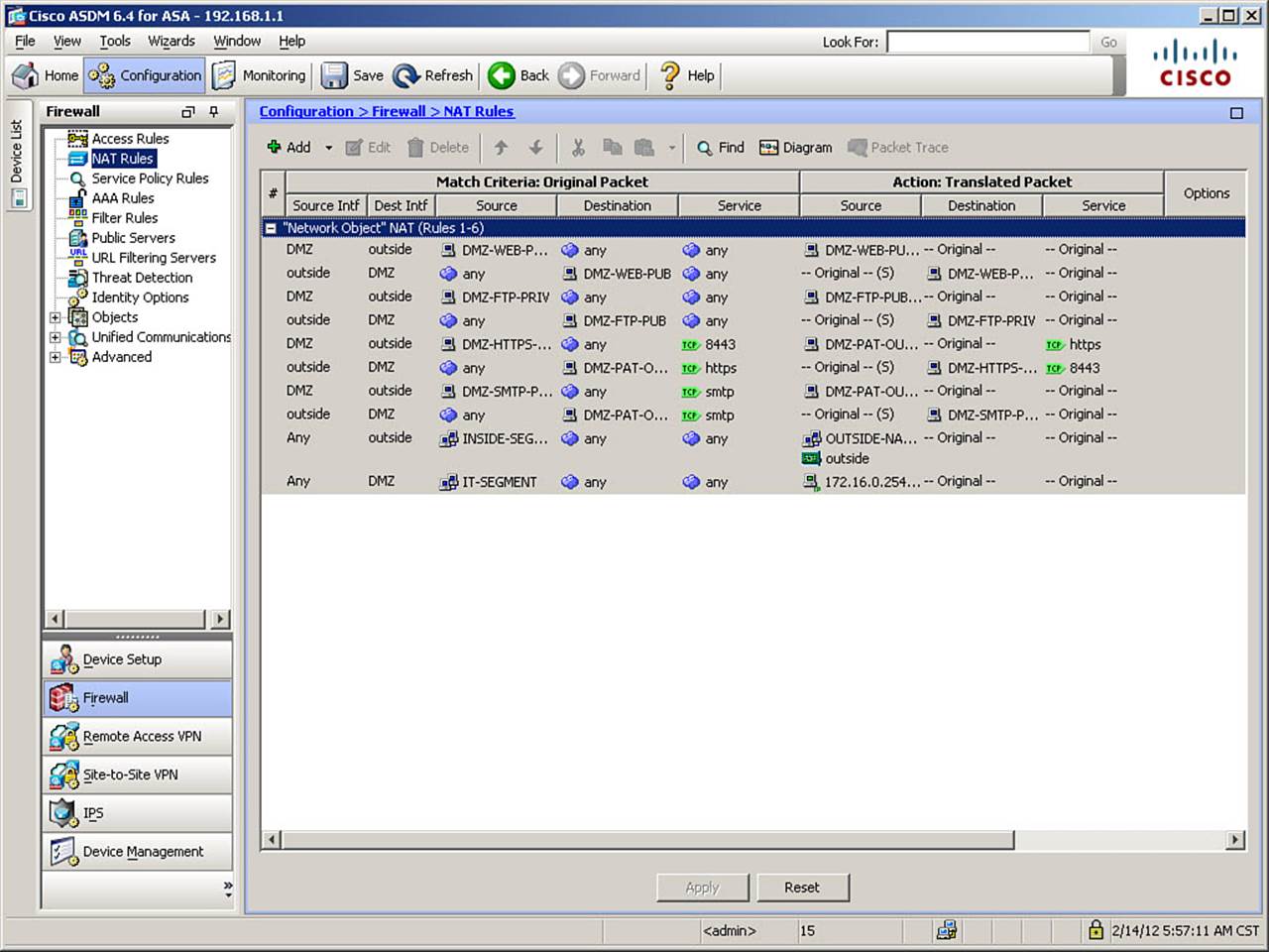
Figure 7-46. ASDM NAT Rules Window
To add the new manual NAT rule, click Add > Add NAT Rule Before “Network Object” NAT to open the Add NAT Rule dialog box, as shown in Figure 7-47.
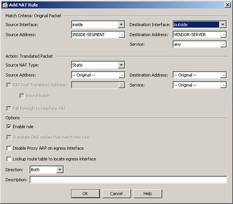
Figure 7-47. Configuring a Manual NAT Rule (Dynamic PAT)
As you can see in Figure 7-47, there are a wide variety of configuration options within this one window. The Match Criteria section allows you to define a traffic flow, as an access list did in OS versions 8.2 and earlier when creating policy NAT/PAT rules. The Action section allows you to specify that the source, destination, or both addresses from a matching packet be altered to new values. Finally, in the Options section, in addition to being able to quickly enable or disable (without deleting) the rule, you can activate DNS Rewrite (which functions as previously described in the section, “Other NAT Considerations”), and a new option, Direction, which can make NAT rules unidirectional. (Translation occurs in only one direction; no translation occurs in the other direction.)
In the Match Criteria section, from the drop-down list as the Source Interface (ingress), select the inside interface. Then, click the ellipsis (...) button for the Source Address field, and using procedures previously demonstrated, assign the network object INSIDE-SEGMENT as the source address, as shown in Figure 7-47.
For the destination interface (egress), select outside from the drop-down list. In the Destination Address field, you might think you could simply type the vendor server address of 192.0.2.50, but this is not the case. In manual NAT rules, you can specify only any, an object or object group name, or an interface name. Therefore, click the ellipsis button and, using procedures already demonstrated, create a new network object named VENDOR-SERVER, defined as the host 192.0.2.50, and assign it as the destination address. These changes are shown in Figure 7-47.
To demonstrate the syntax of port mapping in a manual NAT rule, this scenario had the vendor server listening on port 8443. Rather than make users on the inside network specify this port when attempting to connect, you decide to create port mapping in the ASA’s NAT rule to handle the redirection automatically from an original destination port of 443 (used by the inside clients by specifying an HTTPS URL in their browser) to port 8443, the actual listening port on the vendor server. Although creation of service object groups is covered in Chapter 8, Figure 7-48 shows an example for purposes of this scenario. Click the ellipsis button for the Service field, and then click Add > Service Object to open the Add Service Object dialog box, as shown in Figure 7-48.
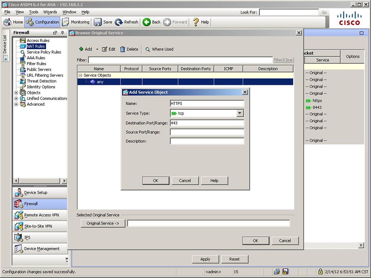
Figure 7-48. Configuring a Service Object
Enter a name for the service object in the Name field. Figure 7-48 shows the creation of the object HTTPS. Leave the service type set to the default of TCP. In the Destination Port/Range field, enter the original destination port value of 443. Click OK to complete the creation of the service object, and assign it as the original destination service using the procedures already demonstrated.
Figure 7-49 shows the continuation of configuration in the Add NAT Rule dialog box, following the creation of the new service object.
Figure 7-49. Completing the Manual NAT Rule Configuration
In the Action section of the window, set the Source NAT Type to Dynamic PAT (Hide), because the scenario specified translation to a single IP address. In the Source Address field, once again, only an object or object group name, or an interface name, are allowed as inputs. So, create and assign a new network object named VENDOR-SERVER-PAT, defined as the host address 209.165.200.234, as shown in Figure 7-49. Leave the Destination Address field at its default value of “—Original—”, indicating no translation is to occur to the destination address in matching packets. Then, using procedures already demonstrated, create and assign a service object named VENDOR-PORTMAP, defined as destination port 8443, in the Service field. These changes are all shown in Figure 7-49.
All newly created rules are enabled by default, so no further changes are necessary (although you can optionally enter a description for this rule, if desired). Click OK to complete the definition of the new manual NAT rule.
Note
Because this example alters both source and destination information in subject packets, the equivalent configuration in OS versions 8.2 and earlier require multiple rules using a combination of dynamic inside policy NAT and static outside PAT, as those versions are limited to altering only source information in packets.
Verify that the new rule appears in the NAT Rules window, above the “Network Object” NAT section, and click Apply to send the changes to the ASA.
The CLI commands generated by the changes made are as follows (spacing inserted for readability):
object network VENDOR-SERVER
host 192.0.2.50
!
object network VENDOR-SERVER-PAT
host 209.165.200.234
!
object service HTTPS
service tcp destination eq https
!
object service VENDOR-PORTMAP
service tcp destination eq 8443
!
nat (inside,outside) 1 source dynamic INSIDE-SEGMENT VENDOR-SERVER-PAT destination
static VENDOR-SERVER VENDOR-SERVER service HTTPS VENDOR-PORTMAP
If you are configuring the ASA from the CLI, you can directly enter these commands in global configuration mode.
Note
Although the modification of destination information in the scenario just presented would technically make this a twice NAT rule, that term is more typically used when both source and destination addresses are being altered.
Examining the Syntax of the Manual NAT Command
The syntax of the manual NAT nat command is somewhat complex at first glance, so it warrants a close examination:
nat (inside,outside) 1
The initial section specifies that the rule applies for packets sourced from the inside and destined to the outside interface. Thus, it specifies both ingress and egress interfaces. Also, the number 1 indicates the order in which this rule is to appear in the Manual NAT section of the NAT Table. Recall that manual NAT allows for multiple translation rules for the same network object, with different matching conditions, and that NAT is applied from top to bottom in the NAT Table, so the order of rules becomes important.
For example, assume one manual NAT rule specified that traffic from source A to destination B, with destination port 80, were to be translated a particular way. Another specifies that all other traffic from source A to destination B is to be translated differently. It is obvious that these rules must appear in the correct order or they would not function as intended.
Auto NAT rules did not require ordering, because auto NAT only allows a single NAT rule per network object.
source dynamic INSIDE-SEGMENT VENDOR-SERVER-PAT
This section specifies how the source (original) address in a matching packet is to be translated (in this case, dynamically). It also specifies the original address, which defines the matching condition (in this case, the network object INSIDE-SEGMENT), and the source address after translation (in this case, the network object VENDOR-SERVER-PAT) in that order.
destination static VENDOR-SERVER VENDOR-SERVER
This section specifies how the destination address in a matching packet is to be translated, if at all. In this case, to indicate that no translation is to occur, the rule specifies that the destination address is to be “statically translated to itself.”
service HTTPS VENDOR-PORTMAP
The final section specifies the configured portmap rule. If a manual NAT rule does not contain port mapping, this section would simply not exist, and the command would end with the destination address mapping information. Also, note that port mapping is only available for destination, not source, information. The service objects are listed in the order of original port, then translated port, so this example will translate a destination port of 443 to a destination port of 8443 for packets from the INSIDE-SEGMENT object to the VENDOR-SERVER object.
Configuring a NAT Exemption Using Manual NAT
Returning to the configuration scenario, requirement 3 is the equivalent of a policy NAT exemption in OS versions 8.2 and earlier. This configuration is actually quite straightforward.
First, using procedures already demonstrated, create a new network object named SATELLITE-OFFICE, defined as the network 10.10.10.0/24. Then, from the NAT Rules window, click Add > Add NAT Rule Before “Network Object” NAT to open the Add NAT Rule window, as shown inFigure 7-50.
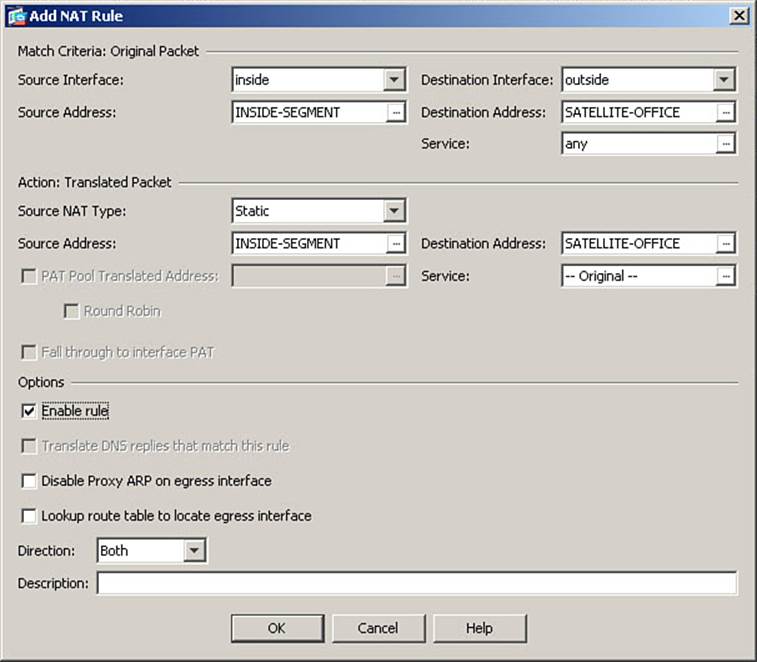
Figure 7-50. Configuring a Manual NAT Exemption Rule
In the Match Criteria section of the dialog box, select the inside interface, and the object INSIDE-SEGMENT as the source of packets subject to the rule. Select the outside interface and the new object SATELLITE-OFFICE as the destination, as shown in Figure 7-50.
In the Action section, choose static as the source NAT type, and then repeat the selections of INSIDE-SEGMENT and SATELLITE-OFFICE as the source and destination addresses, respectively. These changes are also shown in Figure 7-50.
Click OK to complete the definition of this new NAT rule. Figure 7-51 shows the NAT Rules screen following this configuration. Note that the new NAT rule appears on two lines: one for traffic from inside to outside and one from outside to inside. Both lines specify “Original” in all the columns under the Action: Translated Packet header, indicating neither source nor destination addresses are to be altered in the packets that match this rule.
Figure 7-51. NAT Rules Window Showing New Manual NAT Rules
Configuring Twice NAT
Requirement 4 in our NAT scenario introduces the need for twice NAT, because of the overlapping IP addresses involved. Prior to OS version 8.3, such a scenario was usually handled by performing inside policy NAT at each end of a VPN tunnel with overlapping addresses.
Figure 7-52 provides an illustration of the situation.
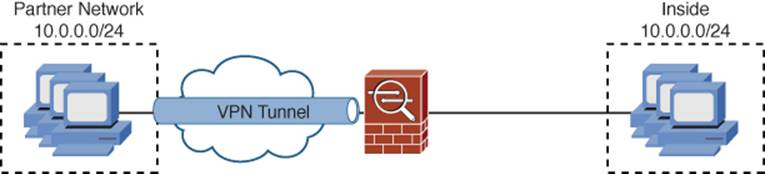
Figure 7-52. VPN with Overlapping Address Ranges
With OS versions 8.3 and higher, twice NAT makes it possible to handle the necessary address translations entirely on one ASA. Because all NAT rules now have the capability to specify destination interfaces, a routing decision is no longer necessary to select an egress interface, so overlapping addresses no longer present the difficulty they once did.
To configure this solution, using procedures already demonstrated, open the Add NAT Rule dialog box, as shown in Figure 7-53.
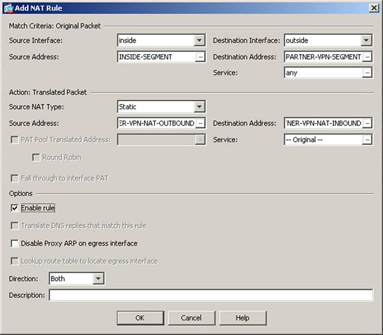
Figure 7-53. Configuring a Twice NAT Rule
Specify the inside interface and object INSIDE-SEGMENT as the source information for this twice NAT rule. Select the outside interface as the destination interface. Although you could, because the addresses are the same, define the INSIDE-SEGMENT object as the destination address, this might cause confusion when reading the configuration. Therefore, using procedures already demonstrated, create and apply a new object named PARTNER-VPN-SEGMENT, defined as the network 10.0.0.0/24. These settings are shown in Figure 7-53.
Recall that our requirement was for full bidirectional (any-to-any) connectivity. Therefore, each internal host in the INSIDE-SEGMENT object must be uniquely identifiable from the partner network, and vice versa. Therefore, you must use static NAT, and not PAT, to accomplish this objective. The administrators of the partner network requested that you translate traffic to use source address 192.168.10.0/24 for this VPN.
In the Action section of the dialog box, select Static as the Source NAT Type. Then, using procedures already demonstrated, create and assign a network object named PARTNER-VPN-NAT-OUTBOUND, defined as the network 192.168.10.0/24, in the Source Address field, as shown inFigure 7-53.
Because the partner network uses overlapping addressing to your own, it is also necessary to translate the destination address in packets. For example, if one of your inside hosts were to attempt to send packets to the destination address 10.0.0.50, it would be considered local segment traffic and would not be routed to the ASA as the default gateway for the inside host. Therefore, inside hosts must use a destination address that requires routing the packet to the ASA, which then translates that address into the corresponding 10.0.0.0 address used on the partner network. Therefore, using procedures already demonstrated, create and assign a new network object named PARTNER-VPN-NAT-INBOUND, defined as the network 192.168.20.0/24, in the Destination Address field.
Figure 7-54 provides an illustration of the functionality of this new twice NAT rule.
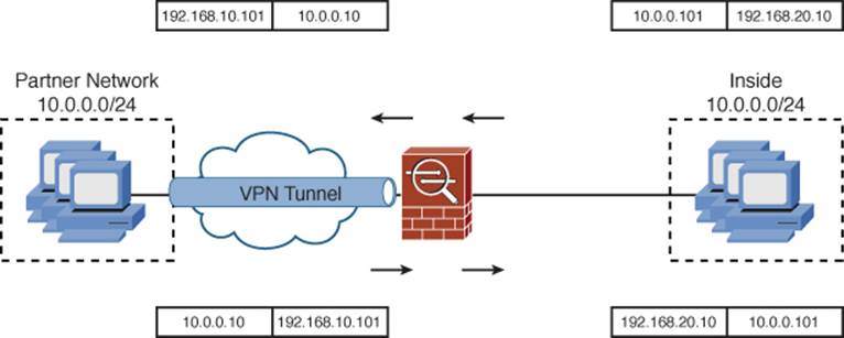
Figure 7-54. Twice NAT Functionality
To complete the configuration of this scenario, click OK to complete the new twice NAT rule, and then click Apply to send the changes to the ASA.
The CLI commands generated by the changes made are as follows (spacing inserted for readability):
object network PARTNER-VPN-NAT-INBOUND
subnet 192.168.20.0 255.255.255.0
!
object network PARTNER-VPN-NAT-OUTBOUND
subnet 192.168.10.0 255.255.255.0
!
object network PARTNER-VPN-SEGMENT
subnet 10.0.0.0 255.255.255.0
!
object network SATELLITE-OFFICE
subnet 10.10.10.0 255.255.255.0
!
nat (inside,outside) 2 source static INSIDE-SEGMENT INSIDE-SEGMENT destination
static SATELLITE-OFFICE SATELLITE-OFFICE
!
nat (inside,outside) 3 source static INSIDE-SEGMENT PARTNER-VPN-NAT-OUTBOUND
destination static PARTNER-VPN-SEGMENT PARTNER-VPN-NAT-INBOUND
If you are configuring the ASA from the CLI, you can enter these commands directly in global configuration mode.
Configuring Translations Using Manual NAT After Auto NAT
Manual NAT “after auto NAT” allows for translations to occur in packets that do not match any more specific translation rules in the NAT Table. They are configured in the same way as other manual NAT rules, with the exception that they are specifically configured to be placed in Section 3 of the NAT Table, rather than Section 1.
The configuration scenario for this example is as follows: Recall that the object IT-SEGMENT has an auto NAT rule defined, performing PAT whenever a host on that segment communicates with the DMZ segment. The ASA is configured to allow a combination of NAT/PAT for internal hosts communicating to the outside interface. A perimeter router at the edge of your network has access rules which drop any packets from the inside network destined to specific web sites, due to the presence of “hacking tools” on those sites. It is well known that what is a hacking tool in the wrong hands is frequently, in the hands of a properly trained administrator, an excellent network auditing tool. Therefore, you need to create a manual NAT after auto NAT rule, which will translate the source address of packets from the IT-SEGMENT to a different PAT address than other internal hosts use, so that the IT-SEGMENT will have access to the restricted web sites. You will use the translated source address 209.165.200.233 for this purpose.
Using the procedures already demonstrated, create a translation object named IT-OUTSIDE-PAT defined as the host address 209.165.200.233. Then, navigate to the NAT Rules screen. Click Add > Add NAT Rule After “Network Object NAT Rules”, as shown in Figure 7-55.
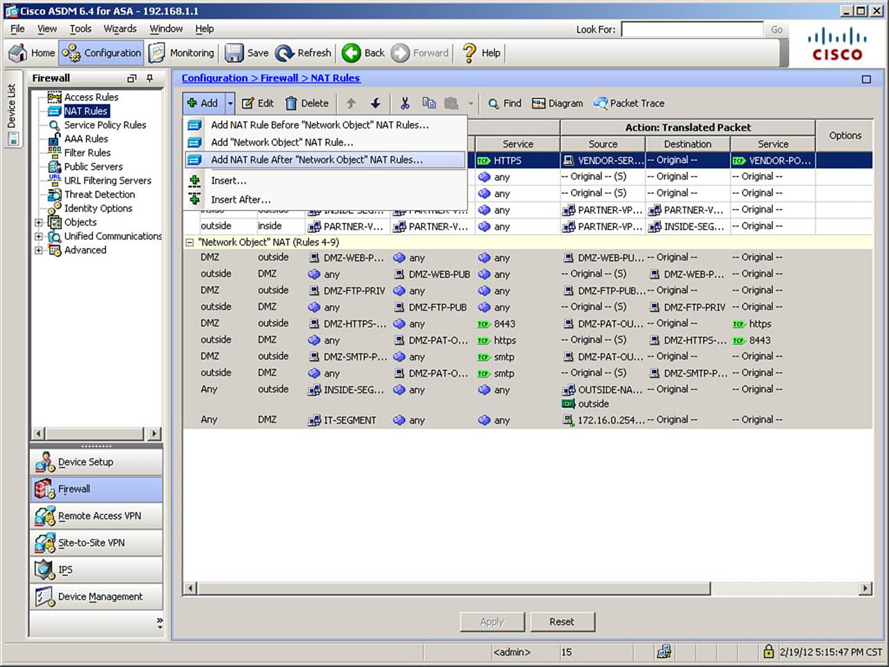
Figure 7-55. Adding a Manual NAT After Auto NAT Rule
This opens the Add NAT Rule After “Network Object” NAT Rules window, as shown in Figure 7-56.
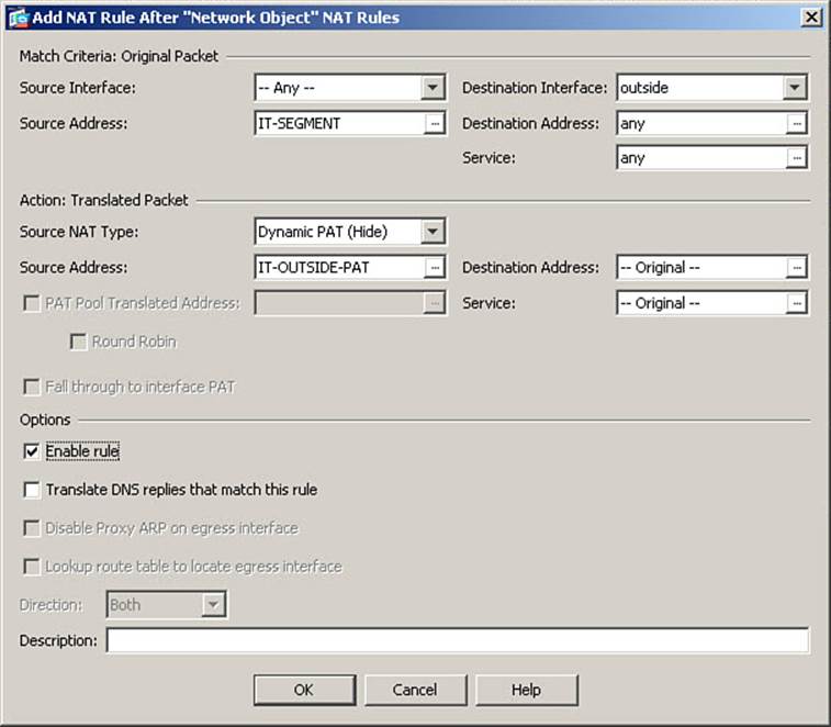
Figure 7-56. Configuring a Manual NAT After Auto NAT Rule
Naturally, this window is organized exactly the same way as the Add NAT Rule window previously shown. A few options, because they would only apply to specific rules that would need to appear in Section 1 of the NAT Table are not present, but the window is laid out the same way.
Under Match Criteria, leave the Source Interface field at the default value of Any and select the IT-SEGMENT object previously defined as the source address. Select outside as the destination interface, and leave the destination address and service set as any. These changes are shown inFigure 7-56.
In the Action section, set the Source NAT Type to Dynamic PAT (Hide). For the source address, select and assign the object IT-OUTSIDE-PAT you just created. Leave all other fields at their defaults, and click OK to complete the configuration of this new rule. Finally, click Apply to send the changes to the ASA.
The CLI commands generated by the changes made are as follows (spacing inserted for readability):
object network IT-OUTSIDE-PAT
host 209.165.200.233
nat (any,outside) after-auto 1 source dynamic IT-SEGMENT IT-OUTSIDE-PAT
If you are configuring the ASA from the CLI, you can enter these commands directly in global configuration mode.
Note the keyword after-auto, which is inserted into the nat command. This option specifies that the NAT rule will be placed after the auto NAT section of the NAT Table and is the only syntax that differentiates a manual NAT from a manual NAT after auto NAT rule.
Configuring a Unidirectional Manual Static NAT Rule
There are occasions when address translations should not be bidirectional (the default). For example, when connections sourced from a defined object should translate to a particular address, but connections initiated toward that same object, as a destination, should not use that same translated address to refer to the host. To gain access, such connections must match a translation rule that works in both directions.
Unidirectional translation rules are also useful if you want a host to be able to initiate outbound connectivity, but under no circumstances should inbound connections to the host be possible, even if access rules are misconfigured to allow such inbound connections.
Note
Make sure to check the specific release you will be running on your ASA in your production environment, because the unidirectional keyword is considered deprecated in the latest versions of the OS. For the version upon which the FIREWALL exam is based, the unidirectionalkeyword is still a supported option, however.
The configuration scenario is as follows: You decided, for security reasons, to create a unidirectional translation for an internal server, which will use translated address 209.165.200.231 when communicating with the outside interface. You want it to be able to initiate outbound connections, but inbound connection attempts to the 209.165.200.231 address should not be translated and forwarded to the host, regardless of access rules.
Using procedures already demonstrated, create two new network objects, INSIDE-SVRPRIV, defined as host 10.0.0.10, and INSIDE-SVR-PUB, defined as host 209.165.200.231.
Navigate to the NAT Rules window and click Add > Add to open the Add NAT Rule window, as shown in Figure 7-57.
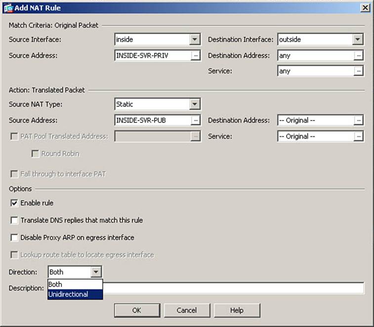
Figure 7-57. Configuring a Unidirectional Manual Static NAT Rule
In the Match Criteria section, select inside as the source interface, and define the object INSIDE-SVR-PRIV as the source address. Select outside as the destination interface. Leave other fields at their defaults. These settings are shown in Figure 7-57.
In the Action section, set the source NAT type as static. Set the source address to the object INSIDE-SVR-PUB. These settings are also shown in Figure 7-57.
Near the bottom of the Options section, locate the Direction field. This field is set to Both (bidirectional) by default. Change the setting to Unidirectional, as shown in Figure 7-57. Then, click OK to complete the creation of the new rule and Apply to send the changes to the ASA.
The CLI commands generated by the changes made are as follows (spacing inserted for readability):
object network INSIDE-SVR-PUB
host 209.165.200.231
!
object network INSIDE-SVR-PRIV
host 10.0.0.10
nat (inside,outside) 4 source static INSIDE-SVR-PRIV INSIDE-SVR-PUB unidirectional
If you are configuring the ASA from the CLI, you can enter these commands directly in global configuration mode.
Inserting a Manual NAT Rule in a Specific Location
Recall that NAT rules are applied to packets by searching the NAT Table, top to bottom, and applying the first rule that matches the packet being analyzed. Because the order of manual NAT rules thus has a specific impact on the operation of NAT on an ASA, it is sometimes necessary to insert a new rule into a specific location in the list. Figure 7-58 shows the NAT Rules window in ASDM with the Add menu expanded.
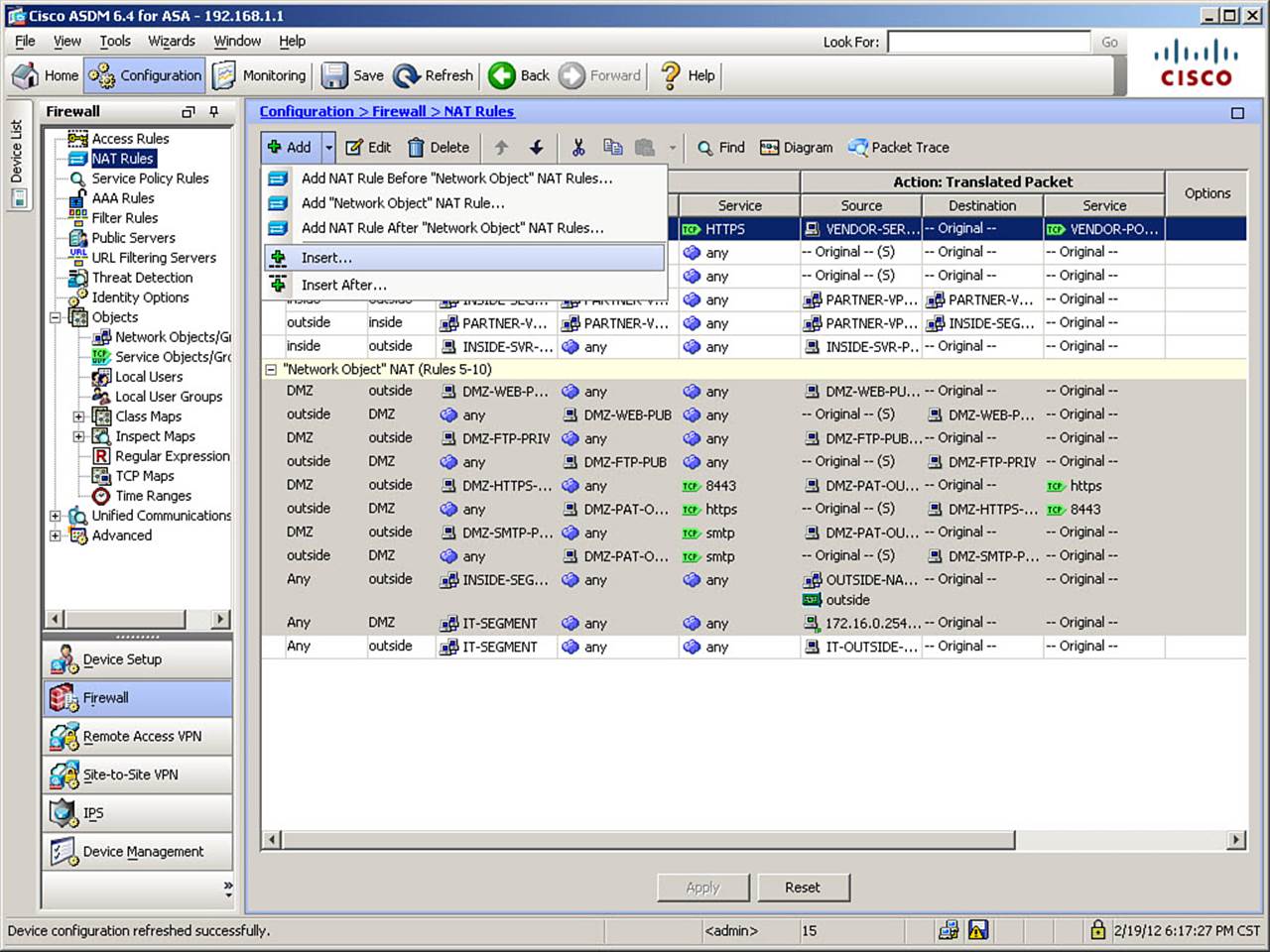
Figure 7-58. Inserting a Manual NAT Rule in a Specific Location
As you can see in Figure 7-58, there are two options for inserting a rule into a specific location within an existing list: Insert and Insert After.
To insert a new rule above a specific rule, highlight that rule, and then choose Insert from the Add menu. Likewise, to insert a new rule below a specific rule, highlight that rule, and then choose Insert After from the Add menu.
NAT rules can also be inserted into specific locations when using the CLI. Recall that each manual NAT rule created has a number that dictates its position within the NAT Table. To insert a new rule between existing rules 3 and 4, for example, assign the new rule position number 4. Existing rules 4 and above will have their position numbers automatically increased by 1.
Comparing Manual NAT Configurations from OS versions 8.2 and 8.3
In comparing manual NAT configurations, consider the configuration just completed for the NAT scenario requirements 2 and 3. It’s been a while since these requirements were presented, so they are repeated here for reference:
1. Several hosts in the 10.0.0.0/24 inside subnet are authorized to connect to a vendor application server, 192.0.2.50, port 8443, on the Internet. This vendor requires all users coming from your organization to appear to their server as a single IP address: 209.165.200.234. Because you are using one-to-one dynamic NAT, each internal host has a unique global address when translated. Thus, you need to configure a manual NAT rule to translate internal hosts to use a configured PAT address if they are communicating with the vendor application server, but still use the previously defined auto NAT rule when connecting elsewhere through the outside interface.
2. You need to configure NAT for a VPN between your inside segment and a satellite office, which uses the IP address 10.10.10.0/24. Because the satellite office also belongs to your company, and you use internal DNS servers, traffic across this VPN needs to be exempted from address translation. Because you already have an auto NAT rule configured to dynamically translate all traffic from the inside segment through the outside interface, a manual NAT rule is required to accomplish this exemption.
Because there are already many things occurring in these examples, we assume a simple two-interface firewall: inside and outside. Example 7-14 shows the version 8.2 configuration, and Example 7-15 shows the corresponding 8.3 configuration that accomplishes the same translations.
Example 7-14. Sample Hybrid NAT Configuration from OS Version 8.2
access-list POLICY-NAT permit tcp 10.0.0.0 255.255.255.0 host 192.0.2.50 eq 443
access-list VPN permit ip 10.0.0.0 255.255.255.0 10.10.10.0 255.255.255.0
static (outside,inside) tcp 192.0.2.50 443 192.0.2.50 8443 netmask 255.255.255.255
nat (inside) 0 access-list VPN
nat (inside) 1 10.0.0.0 255.255.255.0
nat (inside) 200 access-list POLICY-NAT
global (outside) 1 209.165.200.235-209.165.200.254 netmask 255.255.255.224
global (outside) 1 interface
global (outside) 200 209.165.200.234
Example 7-15. Sample Hybrid NAT Configuration from OS Version 8.3
object network INSIDE-SEGMENT
subnet 10.0.0.0 255.255.255.0
object network OUTSIDE-NAT-POOL
range 209.165.200.235 209.165.200.254
object network SATELLITE-OFFICE
subnet 10.10.10.0 255.255.255.0
object network VENDOR-SERVER
host 192.0.2.50
object network VENDOR-SERVER-PAT
host 209.165.200.234
object service HTTPS
service tcp destination eq https
object service VENDOR-PORTMAP
service tcp destination eq 8443
nat (inside,outside) 1 source dynamic INSIDE-SEGMENT VENDOR-SERVER-PAT destination
static VENDOR-SERVER VENDOR-SERVER service HTTPS VENDOR-PORTMAP
nat (inside,outside) 2 source static INSIDE-SEGMENT INSIDE-SEGMENT destination static
SATELLITE-OFFICE SATELLITE-OFFICE
object network INSIDE-SEGMENT
nat (any,outside) dynamic OUTSIDE-NAT-POOL interface
Although the 8.3 configuration is actually more lines in total, the vast majority of it is the configuration of the objects themselves. The translations are configured with only three lines, as compared to the nine lines required in previous OS versions.
The configuration for older OS versions contains a mixture of static and dynamic translations operating on the same packets (in different directions). Nothing in the configuration makes it readily apparent these rules have any relationship to each other, much less that they will be manipulating packets in the same flow. Either of these two facts can also lead to confusion. Furthermore, you need a thorough understanding of NAT rule priority to realize that the rules are actually applied in the order (refer to the section, “NAT Rule Priority,” if desired, to review why this is the order of application):
1. NAT 0 w/ACL
2. Static translation
3. Dynamic NAT rule with NAT ID 200
4. Dynamic NAT rule with NAT ID 1
The combination of these factors presents a real challenge for understanding the configuration, even for experienced administrators. Imagine expanding such an example to the multiple-interface firewalls used in previous examples.
Although the initial creation of the necessary network objects takes some time, the new format rules are much more easily understood and clearly tie together the manipulations occurring to both source and destination information in affected packets.
When Not to Use NAT
Just as with OS versions 8.2 and earlier, there are times when you should not use NAT with OS versions 8.3 and later:
• Do not use NAT or PAT with applications that embed IP addresses on the application layer and use end-to-end encryption, or embed IP addresses on the application layer, and are not specifically supported by ASA advanced protocol inspection.
• Do not use NAT or PAT with applications that authenticate entire packets (such as IPsec Authentication Header [AH] or Border Gateway Protocol [BGP]).
• Do not use NAT or PAT with applications that establish additional dynamic sessions, and for which the ASA does not support protocol-specific inspection rules. Also, if the application uses an encrypted control channel, the ASA will not be able to inspect the packet contents and perform modifications allowing the application to work properly across NAT/PAT.
Tuning NAT
It is sometimes necessary to adjust parameters that affect how the ASA performs NAT and the creation of translation slots. The ASA has many configuration options that can modify behavior. Two that are used fairly commonly are to adjust the global translation slot idle timer and activate DNS rewrite.
Both topics were discussed previously, in the section related to OS versions 8.2 and earlier. Adjusting the global translation slot timer is done exactly the same way in current OS versions as has already been covered. Refer to Figure 7-9 if you want to review this procedure.
The functionality of DNS rewrite was discussed in the section, “Other NAT Considerations.” Activating DNS rewrite on a NAT rule is still done by activating an option with the NAT Rule configuration screen. For this scenario, you will activate DNS rewrite for the auto NAT rule for the DMZ web server.
Using procedures already demonstrated, open the Edit NAT Rule window for the auto NAT rule for the DMZ-WEB-PRIV object. From the Edit NAT Rule window, click the Advanced... button to open the Advanced NAT Settings window, as shown in Figure 7-59.
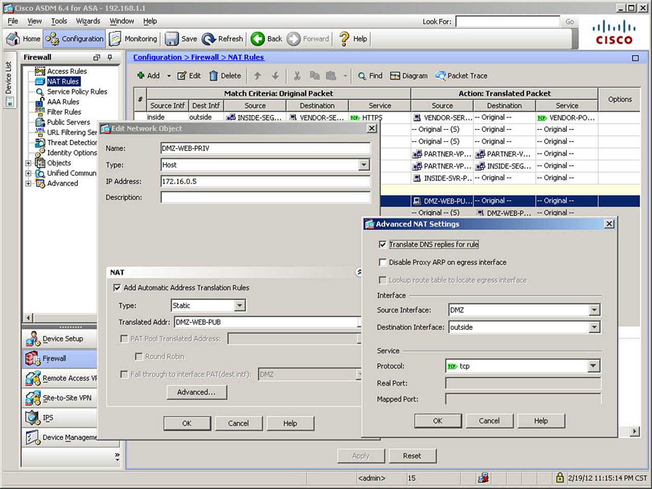
Figure 7-59. Activating DNS Rewrite
To activate DNS rewrite for a NAT rule, in the Options section of the window, check the box titled Translate DNS Replies for Rule. Click OK to accept the new setting, and then click OK again to finish the rule modification. Finally, click Apply to send the changes to the ASA. As was the case with earlier OS versions, this change simply adds the keyword dns to the end of the translation command, as shown here.
The CLI commands generated by the changes made are as follows (spacing inserted for readability):
object network DMZ-WEB-PRIV
no nat (DMZ,outside) static DMZ-WEB-PUB
nat (DMZ,outside) static DMZ-WEB-PUB dns
If you are configuring the ASA from the CLI, you can enter these commands in global configuration mode.
Note
For manual NAT rules, the DNS rewrite option is on the main window for the NAT rule. (There is no Advanced NAT Settings tab for manual NAT rules.) The checkbox is titled Translate DNS Replies That Match This Rule.
Troubleshooting NAT
Troubleshooting NAT requires that you observe activity on the ASA itself while generating traffic to or from a host subject to translation rules. The most common commands used for this purpose are show xlate, show nat, show nat detail, and clear xlate, which have all been examined already in this chapter. It also requires reviewing log messages generated by the address translation process (or access rules).
Improper Translation
If traffic does not appear to be translated according to a configured NAT rule you are expecting to perform the translation, consider performing the following steps in troubleshooting:
Step 1. Verify whether the traffic is being translated at all. Remember that there is no concept of NAT control in OS versions 8.3 and higher, so if NAT rules are improperly configured, traffic might be getting forwarded with no translation occurring. Use the show xlate command to look for translations. Clear the translation table with clear xlate if recent changes have been made to translation rules.
Step 2. If traffic is not being translated, look for missing nat rules by examining the NAT Table. Use the show nat (or show nat detail) command to verify a NAT rule exists for the traffic in question.
Step 3. If traffic is being translated, but not by the correct NAT rule, check for overlapping translation rules. Keep in mind that the NAT Table is examined from top to bottom. If there are conflicting rules, you may need to alter the order of rules in the NAT Table so traffic matches the correct rule.
Example 7-16 shows sample output from the show nat and show nat detail commands for a newly rebooted ASA (noted by all the hit counts being zero). Note more verbose output regarding source and destination addresses and services when using the detail option.
Example 7-16. show nat detail Command Output
FIREWALL# show nat
Manual NAT Policies (Section 1)
1 (inside) to (outside) source dynamic INSIDE-SEGMENT VENDOR-SERVER-PAT
destination static VENDOR-SERVER VENDOR-SERVER service HTTPS VENDOR-PORTMAP
translate_hits = 0, untranslate_hits = 0
2 (inside) to (outside) source static INSIDE-SEGMENT INSIDE-SEGMENT destination
static SATELLITE-OFFICE SATELLITE-OFFICE
translate_hits = 0, untranslate_hits = 0
3 (inside) to (outside) source static INSIDE-SEGMENT PARTNER-VPN-NAT-OUTBOUND
destination static PARTNER-VPN-SEGMENT PARTNER-VPN-NAT-INBOUND
translate_hits = 0, untranslate_hits = 0
Auto NAT Policies (Section 2)
1 (DMZ) to (outside) source static DMZ-WEB-PRIV DMZ-WEB-PUB
translate_hits = 0, untranslate_hits = 0
2 (DMZ) to (outside) source static DMZ-FTP-PRIV DMZ-FTP-PUB
translate_hits = 0, untranslate_hits = 0
3 (DMZ) to (outside) source static DMZ-HTTPS-PRIV DMZ-PAT-OUTSIDE service tcp
8443 https
translate_hits= 0, untranslate_hits = 0
4 (DMZ) to (outside) source static DMZ-SMTP-PRIV DMZ-PAT-OUTSIDE service tcp
smtp smtp
translate_hits = 0, untranslate_hits = 0
5 (any) to (outside) source dynamic INSIDE-SEGMENT OUTSIDE-NAT-POOL interface
translate_hits = 0, untranslate_hits = 0
6 (any) to (DMZ) source dynamic IT-SEGMENT 172.16.0.254
translate_hits = 0, untranslate_hits = 0
Manual NAT Policies (Section 3)
1 (any) to (outside) source dynamic IT-SEGMENT IT-OUTSIDE-PAT
translate_hits = 0, untranslate_hits = 0
FIREWALL# show nat detail
Manual NAT Policies (Section 1)
1 (inside) to (outside) source dynamic INSIDE-SEGMENT VENDOR-SERVER-PAT
destination static VENDOR-SERVER VENDOR-SERVER service HTTPS VENDOR-PORTMAP
translate_hits = 0, untranslate_hits = 0
Source - Origin: 10.0.0.0/24, Translated: 209.165.200.234/32
Destination - Origin: 192.0.2.50/32, Translated: 192.0.2.50/32
Service - Origin: tcp destination eq https, Translated: tcp destination eq 8443
2 (inside) to (outside) source static INSIDE-SEGMENT INSIDE-SEGMENT destination
static SATELLITE-OFFICE SATELLITE-OFFICE
translate_hits = 0, untranslate_hits = 0
Source - Origin: 10.0.0.0/24, Translated: 10.0.0.0/24
Destination - Origin: 10.10.10.0/24, Translated: 10.10.10.0/24
3 (inside) to (outside) source static INSIDE-SEGMENT PARTNER-VPN-NAT-OUTBOUND
destination static PARTNER-VPN-SEGMENT PARTNER-VPN-NAT-INBOUND
translate_hits = 0, untranslate_hits = 0
Source - Origin: 10.0.0.0/24, Translated: 192.168.10.0/24
Destination - Origin: 10.0.0.0/24, Translated: 192.168.20.0/24
4 (inside) to (outside) source static INSIDE-SVR-PRIV INSIDE-SVR-PUB
unidirectional
translate_hits = 0, untranslate_hits = 0
Source - Origin: 10.0.0.10/32, Translated: 209.165.200.231/32
Auto NAT Policies (Section 2)
1 (DMZ) to (outside) source static DMZ-WEB-PRIV DMZ-WEB-PUB
translate_hits = 0, untranslate_hits = 0
Source - Origin: 172.16.0.5/32, Translated: 209.165.200.228/32
2 (DMZ) to (outside) source static DMZ-FTP-PRIV DMZ-FTP-PUB
translate_hits = 0, untranslate_hits = 0
Source - Origin: 172.16.0.10/32, Translated: 209.165.200.229/32
3 (DMZ) to (outside) source static DMZ-HTTPS-PRIV DMZ-PAT-OUTSIDE service tcp
8443 https
translate_hits = 0, untranslate_hits = 0
Source - Origin: 172.16.0.15/32, Translated: 209.165.200.230/32
Service - Protocol: tcp Real: 8443 Mapped: https
4 (DMZ) to (outside) source static DMZ-SMTP-PRIV DMZ-PAT-OUTSIDE service tcp
smtp smtp
translate_hits = 0, untranslate_hits = 0
Source - Origin: 172.16.0.20/32, Translated: 209.165.200.230/32
Service - Protocol: tcp Real: smtp Mapped: smtp
5 (any) to (outside) source dynamic INSIDE-SEGMENT OUTSIDE-NAT-POOL interface
translate_hits = 0, untranslate_hits = 0
Source - Origin: 10.0.0.0/24, Translated: 209.165.200.235-209.165.200.254,
209.165.200.226/27
6 (any) to (DMZ) source dynamic IT-SEGMENT 172.16.0.254
translate_hits = 0, untranslate_hits = 0
Source - Origin: 10.0.1.0/24, Translated: 172.16.0.254/32
Manual NAT Policies (Section 3)
1 (any) to (outside) source dynamic IT-SEGMENT IT-OUTSIDE-PAT
translate_hits = 0, untranslate_hits = 0
Source - Origin: 10.0.1.0/24, Translated: 209.165.200.233/32
Proxy ARP and Syslog Messages
Both of these topics were covered in the “Troubleshooting Address Translation” section in the portion of this chapter covering OS versions 8.2 and earlier. There are no significant differences in these troubleshooting steps when using OS versions 8.3 and higher.
Egress Interface Selection
The ASA uses both the routing table and the xlate table to make routing decisions. In older OS versions, a routing decision was made in order to select the egress interface. Therefore, overlapping address spaces and such could cause significant complication when trying to configure address translation rules.
Now, to manage destination IP translated traffic, the ASA searches for an existing xlate slot (including static translation) to select the egress interface. Recall that ALL translation slots, as of OS version 8.3, include an egress interface. Refer, if desired, to Figure 7-13, the show xlate command output, for the illustration of this fact. Packets are then virtually forwarded to the egress interface. After packets are at the egress interface, an interface route lookup is performed to find the correct next hop(s) that belong to the selected egress interface. Only routes that point out the selected egress interface are eligible. Thus, conflicting IP addressing on local and remote networks can be adequately overcome. Use the show route command to assist with determining if the ASA has correct routes in its configuration.
Exam Preparation Tasks
As mentioned in the section, “How to Use This Book,” in the Introduction, you have a couple of choices for exam preparation: the exercises here, Chapter 17, “Final Preparation,” and the exam simulation questions on the CD-ROM.
Review All Key Topics
Review the most important topics in this chapter, noted with the Key Topic icon in the outer margin of the page. Table 7-4 lists a reference of these key topics and the page numbers on which each is found.
Table 7-4. Key Topics for Chapter 7
Define Key Terms
Define the following key terms from this chapter and check your answers in the glossary:
ingress interface
egress interface
NAT
PAT
xlate table
static NAT
dynamic NAT
inside NAT
outside NAT
dynamic inside NAT
static inside NAT
dynamic outside NAT
static outside NAT
NAT exemption
NAT control
bidirectional NAT
DNS Rewrite
proxy ARP
auto NAT
manual NAT
twice NAT
network object
NAT Table
unidirectional manual static NAT
Command Reference to Check Your Memory
This section includes the most important configuration and EXEC commands covered in this chapter. It might not be necessary to memorize the complete syntax of every command, but you should be able to remember the basic keywords that are needed.
To test your memory of the commands, cover the right side of Table 7-5 with a piece of paper, read the description on the left side, and then see how much of the command you can remember.
Table 7-5. Commands Related to ASA Translation Using OS Versions 8.2 and Earlier
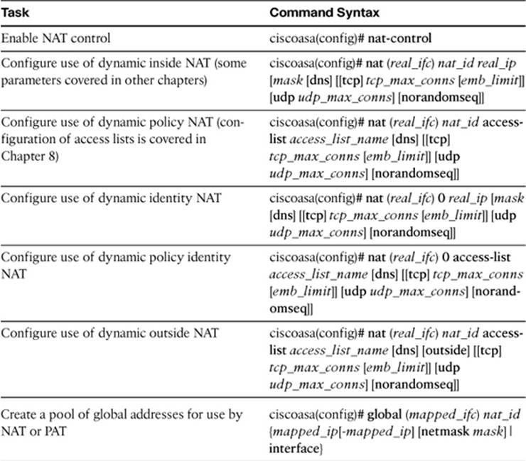
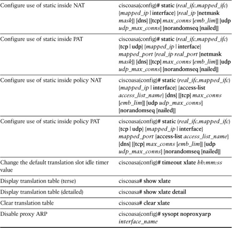
Table 7-6. Commands Related to ASA Translation Using OS Versions 8.3 and Later
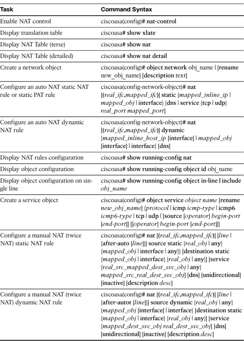
The FIREWALL exam focuses on practical, hands-on skills that are used by a networking professional. Therefore, you should be able to identify the commands needed to configure and test an ASA feature.
All materials on the site are licensed Creative Commons Attribution-Sharealike 3.0 Unported CC BY-SA 3.0 & GNU Free Documentation License (GFDL)
If you are the copyright holder of any material contained on our site and intend to remove it, please contact our site administrator for approval.
© 2016-2026 All site design rights belong to S.Y.A.