CCNP Security FIREWALL 642-618 Official Cert Guide (2012)
Chapter 8. Controlling Access Through the ASA
This chapter covers the following topics:
• Understanding How Access Control Works: This section provides a brief introduction to the information necessary to implement effective access control.
• State Tables: This section describes the two state tables (connection and local host) used by the Cisco ASA to determine if connections should be allowed through the ASA without the need to consult interface access rules, and how to view their contents.
• Understanding Interface Access Rules: This section describes the functionality of interface access rules, the most common access control method deployed on Cisco ASAs.
• Default Access Rules: This section describes the default interface access rules present on an ASA.
• The Global ACL: This section discusses the global ACL, a new concept in OS version 8.3, created to make it easier to configure and manage the access policy configuration.
• Configuring Interface Access Rules: This section demonstrates how to configure interface access rules (ACLs in the CLI), including how to create and edit rules. It also discusses how to activate system logging for specific rules, add comments to your list of access rules, modify logging levels of syslog messages generated by packets matching access rules, and perform ACL creation and editing from the CLI.
• Time-Based Access Rules: This section explains how to create access rules that are applied only at specific times, by creating time ranges and then referencing them in access rules.
• Verifying Interface Access Rules: This section describes methods to verify the content and functionality of interface access rules, including methods of managing access rules from both Cisco ASDM and the CLI.
• Organizing Access Rules Using Object Groups: This section describes the concept of object groups in the Cisco ASA, including the types of object groups, how they are used, and why they are used.
• Verifying Object Groups: This section describes how to verify membership within object groups, as well as in access rule sets (access lists), both in Cisco ASDM and the CLI.
• Configuring and Verifying Other Basic Access Controls: This section describes how to implement and verify the use of Unicast Reverse Path Forwarding and host shunning.
• Troubleshooting Basic Access Control: This section describes how to use various tools effectively on the ASA to troubleshoot issues with access control.
This chapter reviews access control lists (ACL) and host shunning, and how these features can be configured to control traffic movement through a Cisco Adaptive Security Appliance (ASA).
“Do I Know This Already?” Quiz
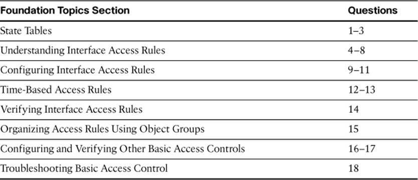
The “Do I Know This Already?” quiz allows you to assess whether you should read this entire chapter thoroughly or jump to the “Exam Preparation Tasks” section. If you are in doubt about your answers to these questions or your own assessment of your knowledge of the topics, read the entire chapter. Table 8-1 lists the major headings in this chapter and their corresponding “Do I Know This Already?” quiz questions. You can find the answers in Appendix A, “Answers to the ‘Do I Know This Already?’ Quizzes.”
Table 8-1. “Do I Know This Already?” Section-to-Question Mapping
1. Which of the following are state tables maintained by the ASA? (Choose two.)
a. Host table
b. Connection table
c. Session table
d. Local host table
e. Xlate table
2. Which of the following would be tracked for a TCP connection? (Choose all that apply.)
a. Source IP address
b. Destination port number
c. Sequence number (in both directions)
d. Acknowledgment number (in both directions)
e. Idle time
f. TCP window size
3. Consider this entry from the connection table:
TCP outside 192.0.2.223:3122 DMZ 172.16.0.10:8400, idle 0:03:13, bytes
244335, flags UIOB
What do the flags UIOB indicate? (Choose all that apply.)
a. This connection is currently up.
b. This connection is currently idle.
c. This connection has seen both inbound and outbound data.
d. This connection was initiated from a lower-security interface to a higher security interface.
e. This connection was initiated from a higher-security interface to a lower security interface.
f. This connection is currently half-closed.
4. If a packet arrives at an ASA interface and is associated with an already-existing connection object, how will it be processed by the interface access rules?
a. In order, until first match.
b. Entire list, applying best match.
c. In order, until first match, but after any address translation is applied.
d. It is not processed by the interface access rules.
5. The initial packet in an SSH session destined for the ASA itself arrives at the ASA interface. How will it be processed by the interface access rules?
a. In order, until first match.
b. Entire list, applying best match.
c. In order, until first match, but after any address translation is applied.
d. It is not processed by the interface access rules.
6. What do all access lists contain as the final rule?
a. Explicit deny all
b. Implicit deny all
c. Transparent deny all
d. Implicit permit all
7. If no interface access rules are applied, what will happen to traffic ingressing the ASA through the DMZ interface, security level 50, and destined for the DMZ2 interface, security level 60?
a. It will be permitted.
b. It will be denied.
c. There is not enough information given to know for certain.
d. It will be permitted only if it passes a uRPF check.
8. Consider the following configuration:
access-list INSIDE-IN permit ip object INSIDE-SEGMENT any
access-list OUTSIDE-OUT permit tcp 10.0.0.0 255.255.255.0 any eq https
access-list GLOBAL-ACL deny ip any any
object network INSIDE-SEGMENT
subnet 10.0.0.0 255.255.255.0
nat (inside,any) dynamic 209.165.200.254 interface
access-group INSIDE-IN in interface inside
access-group OUTSIDE-OUT out interface outside
access-group GLOBAL-ACL global
If host 10.0.0.108 on the inside interface initiates an HTTP connection to server 192.0.2.150 on the Internet, will it be permitted through the ASA?
a. Yes, it will be permitted.
b. No, it will be denied.
9. Consider the following configuration: Which of the following access list statements will allow Internet-based hosts to reach the web server on the DMZ, assuming access list OUTSIDE-IN is applied inbound on the outside interface?
object network DMZ-WEB-SVR
host 172.16.0.5
nat (DMZ,outside) static 209.165.200.228
object-group network WEB-SVRS
network-object host 172.16.0.5
network-object host 172.16.0.10
a. access-list OUTSIDE-IN permit tcp any host DMZ-WEB-SVR eq 80
b. access-list OUTSIDE-IN permit ip any object WEB-SVRS eq http
c. access-list OUTSIDE-IN permit tcp any object DMZ-WEB-SVR eq www
d. access-list OUTSIDE-IN permit tcp any object WEB-SVRS eq http
e. access-list OUTSIDE-IN permit ip any object DMZ-WEB-SVR eq http
10. If you include a description when configuring an access rule in Cisco ASDM, what effect does this have on the access list when viewed from the CLI?
a. None; access rule descriptions are not made part of the configuration file.
b. It will create an access-list remark statement with its own line number, placed directly before the access rule being configured.
c. It will create an access-list remark statement with its own line number, placed directly after the access rule being configured.
d. It will create an access-list remark statement with the same line number as the access rule being configured, placed directly before the access rule being configured.
e. It will create an access-list remark statement with the same line number as the access rule being configured, placed directly after the access rule being configured.
11. When an access rule denies traffic, this is a security event, and the ASA generates which syslog message for each denied packet, by default?
a. 106100
b. 106015
c. 106023
d. 106123
12. July 1, 2012 at midnight through September 31, 2012 at 11:59 p.m. is an example of what type of time range?
a. Definite
b. Periodic
c. Absolute
d. Temporary
13. Where in Cisco ASDM are time ranges configured?
a. Configuration > Firewall > Access Rules > Time Ranges
b. Configuration > Firewall > Advanced > Time Ranges
c. Configuration > Firewall > Time Ranges
d. Configuration > Firewall > Objects > Time Ranges
14. The show access-list brief command displays which of the following? (Choose all that apply.)
a. The access-list id of all access lists configured
b. The number of ACEs in each ACL
c. The hit count for each ACE in each ACL
d. A hexadecimal hash identifier for each access list
15. What are the four types of object groups that can be created on the Cisco ASA?
a. Network
b. ICMP
c. Service
d. Port Range
e. Protocol
f. Server
g. ICMP-type
h. Encryption Domain
16. Where in Cisco ASDM is uRPF enabled?
a. Configuration > Firewall > Access Rules > Anti-Spoofing
b. Configuration > Firewall > Advanced > uRPF
c. Configuration > Firewall > Access Rules > uRPF
d. Configuration > Firewall > Advanced > Anti-Spoofing
e. Configuration > Firewall > Interfaces > Anti-Spoofing
f. Configuration > Firewall > Interfaces > uRPF
17. How can you clear only a single host from the shunning list?
a. clear shun ip_address
b. clear shun interface ip_address
c. clear shun ip_address interface
d. You cannot clear only one entry from the shunning list.
18. What command would create a packet capture consisting only of packets dropped by interface access rules?
a. capture ACL-DROPS type acl-drop
b. capture ACL-DROPS type asp-drop acl-drop
c. capture ACL-DROPS asp-drop acl-drop
d. capture ACL-DROPS acl-drop
e. capture ACL-DROPS interface outside acl-drop
f. capture ACL-DROPS interface outside asp-drop acl-drop
Foundation Topics
Access control is at the heart of the Cisco ASA. The ASA provides an administrator with a full-featured set of access control methods, allowing access between network segments to be tightly controlled.
This chapter discusses the most fundamental of these control mechanisms: interface access rules that enforce Layer 3–4 policy, permanent automatic antispoofing mechanisms, and temporary host-blocking mechanisms that may be required for incident response. These mechanisms are the most common types of access controls deployed in most production networks.
Understanding How Access Control Works
Before implementing the access controls demonstrated in this chapter, you should gather some important input parameters from your network environment. Items you will need to know include the following:
• The desired OSI Layer 3–4 access policy: This information should be based on your local security policy and should specify which hosts are allowed to communicate with each other, using which specific applications. Based on this information, you will build an optimal, least-required-privilege access policy that allows only the required connectivity through the ASA.
• Details of the network topology: This information enables you to properly and optimally design routing on the ASA and deploy automatic antispoofing using the Unicast Reverse Path Forwarding (uRPF) feature.
• Whether there is a need for fast, temporary blocking of specific hosts: This feature may be required by organizations whose policies dictate temporary blocking of hosts that are involved in security incidents, such as denial-of-service attacks. The shunning feature covered in this chapter fulfills such a need.
State Tables
The Cisco ASA is, at its foundation, a stateful packet filtering device that is application-aware, and is capable of verifying the legitimacy and correctness of packets arriving at its interfaces by using various state tables combined with configured access policies. If a packet arrives at an ASA interface, it either must match expected traffic definitions from an existing session or will be compared against the inbound interface security policy applied to that interface.
To determine whether the interface security policy will be applied to packets, therefore, the ASA must be able to determine if arriving packets match expected traffic from an existing connection. The ASA does this by maintaining state tables, as just mentioned. State tables act as short-term memory for the device on active connections. Essentially, the state tables describe the device’s environment; traffic the device has seen in the past, combined with its knowledge of networking protocols and applications, allows it to predict what correct future traffic within the same session will look like.
Connection Table
The most fundamental state table used by the ASA is the connection table (sometimes also called the session table). In the connection table, the ASA tracks all connections that were permitted across the device.
Note
As a reminder, do not confuse the generic term “connection,” which is used to indicate an active communication, for the specific term “connection-oriented.” The connection table maintains information not only on connection-oriented Transmission Control Protocol (TCP) sessions, but also on all active communications, whether TCP, User Datagram Protocol (UDP), or based on advanced protocol inspection capabilities discussed in other chapters.

All packets belonging to existing connections that arrive at an ASA interface must match the currently expected packet properties for that particular connection, as recorded in the connection table. If arriving packets belong to an existing session but do not match the expected properties from the connection table, the ASA will drop the packets.
The connection table is constantly updated based on properties observed in permitted packets. When a packet is permitted to cross through the ASA, the associated connection’s state information is adjusted appropriately, based on the protocol in use for that session. If it is the first packet in a session, a new connection object is created in the connection table. If it is not the first packet, the connection object is updated appropriately. For example, a TCP connection object would have its sequence numbers updated with each permitted packet.
The Cisco ASA tracks various connection properties, depending on the transport protocol on which the tracked session is based. These properties are summarized in Table 8-2 and detailed in the following paragraphs. Note that TCP and UDP are tracked by default, but Internet Control Message Protocol (ICMP) and Encapsulating Security Payload (ESP) are tracked only if specifically configured.
Table 8-2. Statefully Tracked Protocol Information
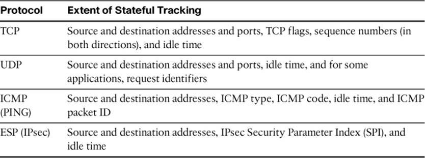
For TCP connections, the ASA tracks a full set of connection parameters, source and destination IP addresses and ports, the TCP state machine (also called TCP flags, to track when a connection is establishing, established, or closing), and the TCP sequence number in both directions. Additionally, by default, for each new connection, the ASA will randomize the initial sequence number of the connection in each direction, and cache the difference between the initial and randomized sequence number, so that all subsequent packets can have the sequence number adjusted accordingly. Finally, the idle time of all TCP connections is tracked so that abandoned or dead connections can be timed out.
A TCP connection object is created in the connection table if the ASA security policy permits its initial synchronization (SYN) packet. If either endpoint closes the connection with a reset (RST), or the endpoints mutually close the connection by exchanging finish (FIN) packets, the connection object is deleted from the connection table. TCP flows can also be deleted by the ASA if they are idle for longer than the configurable TCP idle timer. The ASA also tracks half-closed flows (only one side has sent a FIN), and uses a separate idle timer to delete them if they remain in the half-closed state for that amount of time.
For UDP flows, the ASA tracks source and destination IP addresses and ports and the idle time since the last packet of the flow was seen by the ASA. For certain applications (such as DNS), the ASA also tracks request identifiers, to help it defend against packet-spoofing attacks. A UDP flow connection object is created in the connection table if the ASA security policy permits it. Because UDP flows have no state machine, UDP flows are deleted only when they are idle for longer than the configurable UDP idle timer.
For ICMP pings (for example, ICMP echo and echo reply transactions), the ASA tracks source and destination IP addresses, ICMP type and code, the ICMP packet identifier, and the idle time of the request. An ICMP connection object is created in the connection table if the ASA security policy permits it. When a response is received (e.g., an echo reply from the target, an unreachable message from a router, and so forth), the ICMP connection object is deleted from the connection table. However, by default, the ASA treats ICMP traffic as stateless. Despite being in the connection table, expected ICMP replies will not be permitted through the ASA by default. You must either permit them using an access list or, preferably, enable ICMP inspection, to allow replies to return through the ASA and to enforce the request-response packet-for-packet balance.
For IPsec Encapsulating Security Payload (ESP) tunnel flows through the ASA (the ASA is not an endpoint of the tunnel), the ASA tracks source and destination IP addresses, the Security Parameters Index (SPI, or tunnel ID), and the idle time of the tunnel flow. An IPsec ESP flow connection object is created in the connection table if the ASA security policy permits it. If the tunnel flow is idle for more than the configurable idle time, it is deleted from the connection table. By default, the ASA treats ESP flows as stateless, and does not enter ESP flows into the connection table. To allow returning packets through the ASA “statefully,” you must enable IPsec inspection of pass-through traffic.
Because determinations on which flows to allow through the ASA statefully (without need for an access rule to permit the return session flow) are based on the presence of a connection object in the connection table, it is important to know how to view the contents of the connection table. You can display the current contents of the connection table using the show conn command (which also has several optional parameters, such as detail). Examples 8-1 and 8-2 show the use of the show conn and show conn detail commands, respectively.
Example 8-1. show conn Command Output
FIREWALL# show conn
352 in use, 5985 most used
UDP DMZ 172.16.0.25:161 inside 10.0.0.30:1879, idle 0:00:27, bytes 706509, flags -
UDP outside 192.0.2.18:123 inside 10.0.0.108:123, idle 0:00:34, bytes 79, flags -
TCP outside 192.0.2.150:80 DMZ 172.16.0.5:59512, idle 0:00:00, bytes 0, flags Uf
TCP outside 192.0.2.150:80 inside 10.0.0.102:59559, idle 0:00:03, bytes 1488,
flags UfFRIO
TCP outside 192.0.2.150:80 inside 10.0.0.108:59393, idle 0:00:06, bytes 123013,
flags UIO
TCP outside 192.0.2.150:80 inside 10.0.0.107:59498, idle 0:00:06, bytes 1021,
flags UIO
TCP outside 192.0.2.223:3122 DMZ 172.16.0.10:8400, idle 0:03:13, bytes 244335,
flags UIOB
TCP outside 192.0.2.74:45781 inside 10.0.0.10:389, idle 0:04:01, bytes 9419,
flags UIOB
UDP outside 192.0.2.146:5440 inside 10.0.0.10:5440, idle 0:00:20, bytes 761933,
flags -
TCP outside 192.0.2.6:1047 inside 10.0.0.10:389, idle 0:00:00, bytes 2253, flags UIOB
ICMP outside 192.0.2.37:512 inside 10.0.0.10:0, idle 0:00:00, bytes 0
... output omitted ...
Example 8-2. show conn detail Command Output
FIREWALL# show conn detail
368 in use, 5985 most used
Flags: A - awaiting inside ACK to SYN, a - awaiting outside ACK to SYN,
B - initial SYN from outside, b - TCP state-bypass or nailed, C - CTIQBE
media,
D - DNS, d - dump, E - outside back connection, F - outside FIN, f -
inside FIN,
G - group, g - MGCP, H - H.323, h - H.225.0, I - inbound data,
i - incomplete, J - GTP, j - GTP data, K - GTP t3-response
k - Skinny media, M - SMTP data, m - SIP media,n - GUP
O - outbound data, P - inside back connection, p - Phone-proxy TFTP
connection,
q - SQL*Net data, R - outside acknowledged FIN,
R - UDP SUNRPC, r - inside acknowledged FIN, S - awaiting inside SYN,
s - awaiting outside SYN, T - SIP, t - SIP transient, U - up,
V - VPN orphan, W - WAAS,
X - inspected by service module
UDP DMZ: 172.16.0.25/161 inside:10.0.0.30/1879,
flags -, idle 0s, uptime 1D22h, timeout 2m0s, bytes 706983
UDP outside: 192.0.2.18/61840 DMZ:172.16.0.15/22936,
flags -, idle 29s, uptime 29s, timeout 2m0s, bytes 128
TCP outside:192.0.2.150/80 inside:10.0.0.102/59512,
flags Uf, idle 4s, uptime 9s, timeout 1h0m, bytes 0
TCP outside: 192.0.2.150/80 inside:10.0.0.108/59315,
flags UfFRIO, idle 6m4s, uptime 6m4s, timeout 10m0s, bytes 1493
TCP outside: 192.0.2.150/80 inside:10.0.0.107/59393,
flags UIO, idle 10s, uptime 20s, timeout 1h0m, bytes 123013
UDP outside:192.0.2.146/5440 inside:10.0.0.10/5440,
flags -, idle 24s, uptime 3D23h, timeout 2m0s, bytes 762029
TCP outside: 192.0.2.150/43089 DMZ:172.16.0.5/443,
flags UIOB, idle 2s, uptime 11s, timeout 1h0m, bytes 2296
... output omitted ...
The show conn command displays the number of active connections and information about each. In Example 8-1, there are 11 connections displayed in the connection table output: 3 UDP, 7 TCP, and 1 ICMP.
For each flow, you can see the ASA interfaces involved in the flow, source and destination IP addresses and ports (for TCP and UDP), or session IDs (shown in the same position as the source port field, for GRE and ICMP flows), the current idle time, and the cumulative byte count for traffic flowing between the two endpoints. For TCP connections, connection tracking flags (internal tracking flags used by the ASA, not TCP flags from the packet) are also shown.
Example 8-2 shows similar connections in the connection table. By using the detail keyword, additional information is shown about each connection.
TCP Connection Flags
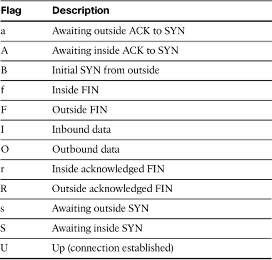
Table 8-3 shows 12 of the most common connection states (flags) seen in the connection table. There are other connection states for specific applications, but the ones shown are valid for any TCP connection in the table.
Table 8-3. Basic TCP Connection States
Note
For a complete list of show conn flag descriptions, consult ASA documentation available on Cisco.com.
Analyzing the TCP flags from the connection table is useful, particularly during troubleshooting, as they can indicate various issues. For example, a connection “stuck” in a state with the flags saA showing indicates an unresponsive host on the interface with the lower security level, and might indicate a routing problem. A connection “stuck” in a state with the flags aB might even indicate a denial-of-service attack is in progress, targeting an internal host. If almost all connections show the UIO (up, inbound data, outbound data) or UIOB (the same, but also indicates that the TCP session was initiated from a lower-security to a higher-security-level direction), this would typically indicate normal ASA operation.
The clear conn command and its variants can be used to delete entries from the connection table. This can be for a single connection, all the way up to all current connections in the table, depending on the parameters you specify.
If you clear a TCP connection, the application using that connection will be disconnected, and may not recover automatically. For other connection types, such as UDP and ICMP, traffic flows will typically re-create the connection object automatically.
Example 8-3 shows a typical use of the clear conn command. In this example, the intent is to clear all connections involving the external host 192.0.2.146, which has recently been the source address on intrusion prevention alerts for servers inside your network. Full parameter options are presented in the section, “Command Reference to Check Your Memory,” at the end of this chapter.
Example 8-3. clear conn Command Usage
FIREWALL# clear conn address 192.0.2.146
12 connection(s) deleted.
Note
Although the Cisco ASA Command Reference Guides state that the clear conn command was introduced as early as OS version 7.0(8), it was included only in specific sub-releases of code versions prior to 8.2. As of 8.2, it is fully supported.
Inside and Outside, Inbound and Outbound
The descriptions in Table 8-3 use the terminology of inside/outside or inbound/outbound when describing connections. These terms portray the security levels of the involved interfaces relative to one another and should not be confused with the interfaces actually named “inside” and “outside” (if such interface names exist). They should instead be interpreted as follows:
• Every connection across the ASA is initiated by an endpoint reachable through one ASA interface and terminates on an endpoint reachable through a different ASA interface. Each ASA interface has an assigned security level, which is a numeric value from 0 to 100, indicating the “trustworthiness” of networks reachable through that interface. The higher the number, the more trust is implied. For example, interface “inside” is given a security level of 100 by default, whereas interface “outside” is assigned a security level of 0.
• For each connection, the inside interface is the interface with the higher assigned security level, and the outside interface is the interface with the lower assigned security level.
• Traffic flowing from an endpoint on a higher-security interface to an endpoint on a lower-security interface is considered outbound. Conversely, traffic flowing from an endpoint on a lower security interface to an endpoint on a higher security interface is considered inbound.
Local Host Table
Another state table maintained by the Cisco ASA is the local host table, where the ASA tracks all IP addresses that have connections established through the ASA. Each individual host (IP address) is tracked with a local host object, where the ASA maintains per-host statistics, such as current connection count. Each local host object references connection objects in the connection table that involve that particular host address. Thus, by viewing the local host table, you can also see the relevant entries from the connection table to which it is linked.
You can view the local host state table using the show local-host command. Because the local host table can be quite extensive, it is very common to filter this output by specifying additional parameters. The most common parameter to specify is the IP address for which you are seeking information. Remember that in the connection table, and therefore the local host table, internal hosts are always represented with their real IP address, and not any mapped IP address from a translation rule, even if the connection is initiated from a less secure interface and the original packets were therefore using a mapped IP address as a destination address. Example 8-4 shows a typical output, where a specific IP address was added as a parameter. Full parameter options are presented in the “Command Reference to Check Your Memory” section at the end of this chapter.
Example 8-4. show local-host Command Output
FIREWALL# show local-host 10.0.0.108
Interface management: 0 active, 0 maximum active, 0 denied
Interface DMZ: 2 active, 69 maximum active, 0 denied
Interface inside: 130 active, 320 maximum active, 0 denied
local host: <10.0.0.108>,
TCP flow count/limit = 15/unlimited
TCP embryonic count to host = 0
TCP intercept watermark = unlimited
UDP flow count/limit = 10/unlimited
Xlate:
NAT from any:10.0.0.108 to outside:209.165.200.238 flags I idle 0:00:00
timeout 3:00:00
Conn:
TCP outside 192.0.2.65:22 inside 10.0.0.108:50124, idle 0:00:58, bytes 443,
flags UIO
... output omitted ...
Interface outside: 120 active, 1940 maximum active, 0 denied
In Example 8-4, internal host 10.0.0.108 has established a Secure Shell (SSH) connection to external host 192.0.2.65. Because the ASA in this example allowed the connection, it will create two objects in the local host table (local host 10.0.0.8 and local host 192.0.2.65) and one object in the connection table (TCP 10.0.0.8:50124 > 192.0.2.65:22), which will be linked to both of the local host table objects.
The local host table is organized by ASA interface, and then by host IP address. For each listed interface, a current connection count and the highest connection count seen since the last reboot are listed, along with a count of any denied connection requests.
The clear local-host command and its variants can be used to delete objects from the local host table. This can be for a single object, a group of objects, or all current objects in the table, depending on the parameters you specify.
If you clear a local host object, all connections associated with that object are also deleted. As with clearing connection objects, some flows may recover automatically, while others may not. Additionally, using the clear local-host command reinitializes per-client runtime states such as connection and embryonic connection limits. As a result, using this command removes any connections that use those limits.
The following syntax shows a typical use of the clear local-host command:
FIREWALL# clear local-host all
In this example, the intent is to clear the entire local host table. It is also possible to clear the local host entry for a single host. This syntax appears in the section, “Command Reference to Check Your Memory,” at the end of this chapter.
State Table Logging
When system logging is enabled on the ASA, it will by default log events associated with the creation and deletion of objects in the connection and local host tables. By default, creation and deletion of local host objects is logged at the debugging (7) level, while creation and deletion of connection objects is logged at the informational (6) level.
The sample output in Example 8-5 shows typical log messages associated with the setup and teardown of a TCP session.
Example 8-5. Log Messages for TCP Session Setup and Teardown
%ASA-7-609001: Built local-host outside:192.0.2.65
%ASA-6-302013: Built outbound TCP connection 977 for outside:192.0.2.65/22
(192.0.2.65/22) to inside:10.0.0.108/55198 (209.165.200.238/55198)
%ASA-6-302014: Teardown TCP connection 977 for outside:192.0.2.65/22 to
inside:10.0.0.108/55198 duration 0:04:06 bytes 156 TCP FINs
%ASA-7-609002: Teardown local-host outside:192.0.2.65 duration 0:04:06
Understanding Interface Access Rules
Interface access rules are the most commonly used access control mechanism on the Cisco ASA. Interface access rules permit or deny the establishment of connections through the ASA, based on the traffic flow’s input and output ASA interfaces, OSI Layer 3 criteria (such as source and destination IP addresses), and OSI Layer 4 criteria (such as source and/or destination TCP or UDP ports).
It should be noted that while the Cisco ASA has supported both standard and extended access lists since version 7.0, all access lists are assumed to be extended (have the capability to specify protocol and both source and destination addresses and ports), unless you specify otherwise. Although standard ACLs do exist on an ASA, they are used for things such as route update filters or VPN split-tunneling definitions and cannot be used for interface access rules.
Effectively, interface access rules determine which new connections can enter the connection state table. If a packet arrives at an ASA interface and is associated with an already existing connection object, it is not operated upon by the interface access rules. If a packet is not associated with an existing connection entry, however, the ASA will compare the packet to the interface access rules. If the rules permit the packet, an object associated with the connection initiated by this packet is created in the connection table, and if the host addresses involved were not previously in the local host table, relevant objects will be created there as well.
Interface access rules control only transit traffic through the ASA—that is, traffic that passes between ASA interfaces but initiates and terminates at endpoints other than the ASA itself. Interface access rules do not control traffic terminating on the ASA itself, such as management connections to the ASA using SSH or HTTPS, ICMP traffic destined for the ASA itself, or traffic associated with VPN tunnels that terminate at the ASA. To control these connections, you must use separate management access rules, discussed in other chapters. Additionally, all traffic sourced by the ASA itself is not subject to interface access rules, and is permitted by default.
Note
Internet Security Association and Key Management Protocol/Internet Key Exchange (ISAKMP/IKE) packets and Encapsulating Security Payload (ESP) packets are always permitted to enter any ASA interface on which ISAKMP is enabled. By default, data packets arriving through a VPN tunnel are also not examined by the interface access rules. However, if you disable the sysopt connection permit-vpn command, packets arriving through a VPN tunnel will be examined by the interface access rules. Even in this case, it is not necessary to explicitly permit ISAKMP/IKE or ESP packets in interface access rules. VPN traffic is covered in detail in a different course and exam from what this book is intended to address, so consult those resources for more detailed coverage of this topic.
Interface access rules are an ordered list of permit and deny statements, evaluated sequentially from the top down. The first rule that matches the new connection packet being evaluated will permit or deny the connection. Once a rule matches an evaluated packet, all subsequent rules are ignored, so order of entries is very important. All access rule sets, which contain explicit rules, contain an implicit deny (an “invisible” deny all) rule as the final rule. Therefore, if a new connection does not match any of the explicit permit rules in an interface rule set, it will be denied (dropped) by default.
Note
Default interface access rule sets, covered in the section, “Default Access Rules,” do not contain any explicit rules, and therefore have no implicit deny. This is critical for understanding the functioning of the global ACL, which is also covered later, in the section, “The Global ACL.”
Stateful Filtering
Because the Cisco ASA is a stateful packet filtering device, interface access rules rely on the presence of the state tables previously described to simplify rule creation. Interface access rules only need to permit the initial packet of a connection, for all protocols and applications that are handled statefully by the ASA. This means your interface access rules do not have to account for the following:
• Any traffic flowing in the reverse direction (return traffic) of that connection. For example, if an internal host initiates a connection to a web server on the Internet, the web content returned does not need to be explicitly permitted in the access rule applied to the outside interface. Because these packets are associated with a flow for which a connection table object exists, they will be automatically permitted by the ASA, as long as they match the properties expected from them by the connection table (for instance, a sequence number within an expected range).
• Any additional connections/flows established by an application. Because the ASA is application-aware for most applications that establish dynamic sessions (such as FTP data channels, Session Initiation Protocol (SIP) voice channels, SQL redirect connections, and so forth), it will automatically permit any additional connections established by the same application session, if you permit the initial packet of the application’s session (sometimes called the “control channel”).
Consider the example illustrated in Figure 8-1. Host 10.0.0.108, attached to the inside interface of the ASA, wants to initiate an HTTP connection to web server 192.0.2.150, somewhere in the Internet.
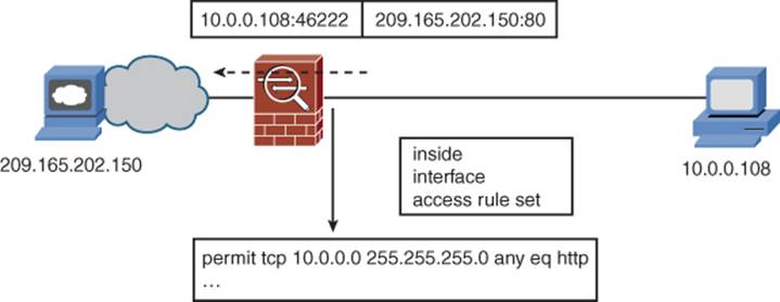
Figure 8-1. Access Rules Example
When the initial packet of the session arrives at the inside interface of the ASA, the ASA compares the packet to the connection table and determines that this packet is not associated with any existing connection entries. Therefore, the packet is compared to the interface access rules. The rule shown in Figure 8-1 permits the connection, so the ASA creates two local host objects and a connection object, in those respective state tables. All subsequent packets associated with this session are allowed through the ASA without regard to the contents of interface access rules.
Figure 8-2 shows the continuation of this session, with emphasis on the stateful handling of the now-established connection.
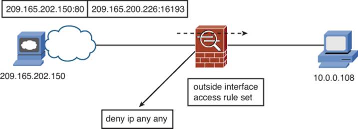
Figure 8-2. Stateful Connection Example
Figure 8-2 shows an example where the access rules on the outside interface of the ASA deny all traffic (for the sake of simplicity). Because of the stateful nature of inspection on the ASA, the return traffic from server 192.0.2.150 is permitted because it matches the connection entry created when the session was established.
If a protocol is not handled statefully by the ASA (for example, applications that do not use TCP or UDP for transport, or ICMP or ESP transit packets, if appropriate inspection is not configured), the ASA is not able to bidirectionally track the session. For such flows to transit the ASA, you will need to explicitly permit the flow’s packets using the access rules applied to all ASA interfaces involved in the traffic flow.
Interface Access Rules and Interface Security Levels
Although it is typically recommended to apply access rules to all ASA interfaces, this is optional. In the absence of a specific set of access rules on an interface, the ASA will apply its default access policy to packets arriving at the interface, as detailed here:
• All outbound connections (initial packet ingresses the ASA through an interface with a higher security level than that of the egress interface selected by routing) are permitted.
• All inbound connections (initial packet ingresses the ASA through an interface with a lower security level than that of the egress interface selected by routing) are denied.
Connections between interfaces with the same security level are denied by default; however, if you use the same-security-traffic permit inter-interface global configuration command (covered in Chapter 3, “Configuring ASA Interfaces”), the handling of connection requests depends on whether the interface receiving the initial packet has an access rule applied:
• If no access rule is applied, traffic between interfaces with the same security level is permitted, based on the same-security-traffic command.
• If an access rule is applied, then traffic between interfaces with the same security level must be explicitly permitted in the access rule, in addition to the global same-security-traffic command.
The other case to consider is when a packet will ingress and egress the ASA through the same interface (needed in certain VPN configurations). By default, the ASA does not allow packets to ingress and egress through the same interface. If you need to allow such traffic flows, you can use the same-security-traffic permit intra-interface global configuration command (covered in Chapter 3). As with inter-interface traffic, the flows will be permitted in the absence of an access rule on the interface being used. However, if an access rule is in place, it may need to permit the required connections, depending on your VPN configuration.
Interface Access Rules Direction
An access rule can be applied to an interface in either an inbound (traffic ingresses the ASA through the interface) or an outbound (traffic egresses the ASA through the interface) direction. This use of the terms inbound and outbound in this case is thus specific to the interface where the ACL is applied, and should not be confused with the terms inbound and outbound used earlier to refer to relative interface security levels.
To be permitted to transit the ASA, an initial packet in a flow must be permitted through all access rules it encounters in its initiating direction. Figure 8-3 shows an example of this.
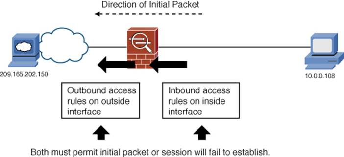
Figure 8-3. Inbound and Outbound Access Rules in Flow Path
In Figure 8-3, an application session is initiated by a host on the inside interface, destined for a host on the Internet (reachable through the outside interface). For this session to be permitted and a connection object to be created in the connection table, the initial packet in the session would have to be permitted both by the access rules applied to the inside interface in an inbound direction and by any access rules applied to the outside interface in an outbound direction.
A common strategy used with Cisco ASAs is to apply only inbound access rules to the various ASA interfaces. This simplifies configuration by using a consistent approach no matter whether controlling access from higher- to lower-security interfaces or vice versa. If access rules are applied to every ASA interface, this approach guarantees that each initial packet of a session is processed by exactly one set of interface access rules, on the interface where the packet ingresses the ASA. Thus, you need only ensure that an application’s traffic is permitted by one set of access rules to ensure it is allowed through the ASA.
In rare situations, it can be useful to also use outbound interface access rules. Figure 8-4 shows such an example.
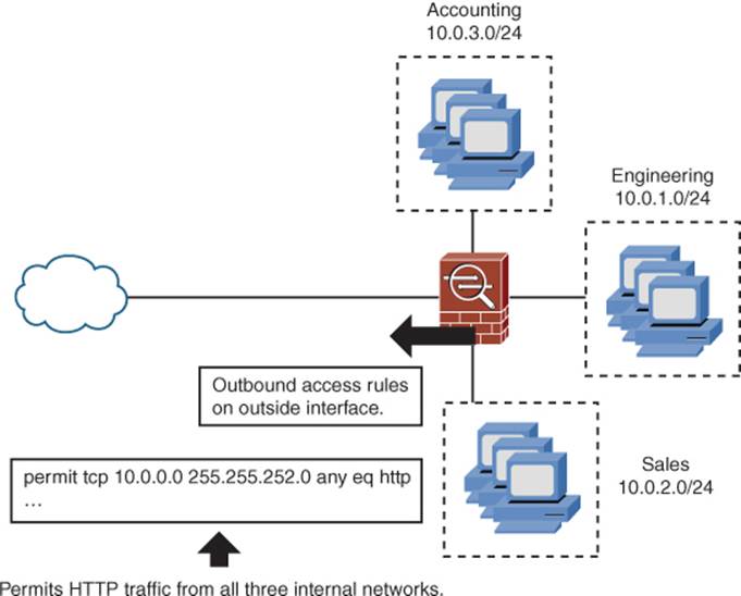
Figure 8-4. Outbound Interface Access Rule Example
In Figure 8-4, the ASA has an outside interface, with security level 0, and three internal interfaces, one each for the Sales, Accounting, and Engineering departments, all having security level 100. Because all three interfaces have the same security level, they are by default isolated from each other. If the goal is to keep them isolated from each other, but to provide all three with access to the Internet through the outside interface, simply applying one set of access rules, outbound on the outside interface (to govern what connectivity is allowed from all three departments) might be easier than applying three separate inbound interface access rules, one on the interface for each department. Obviously, this would depend on what other security policies are in place and how they would be affected by this approach.
Default Access Rules
Before any user-configured access rules are defined or applied, the ASA begins with a default set of interface access rules. If you are using Cisco ASDM to create your access rules, you will use the Cisco ASDM Access Rules table. You can find this table, with its default set of rules, by navigating to Configuration > Firewall > Access Rules, with results similar to those shown in Figure 8-5.
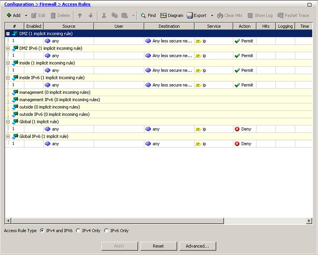
Figure 8-5. Default Interface Access Rules
The Cisco ASDM Access Rules table is a consolidated view of all interface access rules that are configured and applied on the ASA interfaces. The default rules operate under the strategy mentioned previously, wherein one rule set is applied to each interface, in an inbound direction. The default rule set shown is therefore the default set of rules applied to traffic as it ingresses the ASA through the indicated interface. Note that all rules shown have a description that states they are “implicit” rules. This means that if you were to access the CLI and execute the show access-listscommand, you would not see any output, as none of these rules are explicitly defined, but rather are representations of how the ASA handles traffic based on default rules regarding interface security levels. Note the presence of the global access rule, which is discussed in the next section.
By default, the Access Rules table displays both IPv4 and IPv6 access rules on all interfaces. You can use the Access Rule Type selector at the bottom of the window to declutter the display by choosing to show only IPv4 or only IPv6 rules, which is generally recommended if you use a large rule set or only use one IP version within your environment. Figure 8-6 shows the default rule set, with only IPv4 rules displayed.
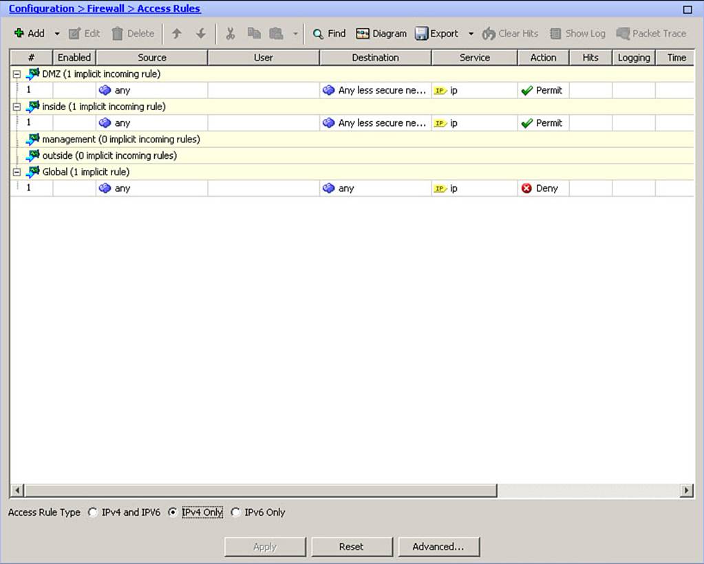
Figure 8-6. Default IPv4 Interface Access Rules
The Global ACL
The global ACL is a new concept, introduced in OS version 8.3, to make it easier to configure and manage the access policy configuration of an ASA.
Any traffic ingressing any ASA interface and not matching a rule in the interface-specific access rule set (including implicit rules) is compared to the global ACL looking for a match. Thus, the global ACL can be thought of as being logically appended to each interface access rule set.
Access rules for the global ACL are configured in the same manner as for an interface rule set; however, if you define any explicit rules within the global ACL, all implicit interface access rules (which permit all traffic flows destined for lower security-level interfaces) are removed, and the global ACL is used to evaluate all traffic ingressing that interface. This is probably a good idea from a security “best practices” viewpoint; however, it can wreak havoc on a network in which the ASA was configured to take advantage of the implicit permit rules. Therefore, carefully review the full impact before defining explicit rules within the global ACL.
As shown in Figure 8-6, with no explicit rules defined, the inside and DMZ interfaces, because they have security levels other than zero and are not configured for management-only, have a default rule set that permits all traffic to less secure networks (lower-security interfaces). Because the outside interface has security level zero, it is not possible for it to access any less secure networks, so it has no interface-specific default rule set. Finally, because the management interface is configured for management only, it does not allow any transit traffic. Each rules set then has the global ACL “deny any any” rule logically appended to them. Therefore, the outside interface, with no interface-specific rule set, has an effective rule set of “deny any any” based on all packets being compared to the global ACL.
Configuring Interface Access Rules
After you have a comprehensive understanding of the methods of applying interface access rules, along with the security policy you intend to implement with them, you can begin configuring interface access rules. The major tasks you need to perform are as follows:
1. Configure individual rules within a commonly named rule set.
2. Optionally, if you plan to use objects or object groups in access rules, configure object and/or object group definitions.
3. Optionally, if you are using objects or object groups in access rules, configure rules that use the configured objects or object groups.
4. Optionally, if you plan to use time-based access rules, configure time range definitions.
5. Optionally, if you are using time-based access rules, configure rules that use the configured time ranges.
6. Apply the rule set to an interface in an inbound or outbound direction.
Note
Network objects were discussed in Chapter 7, “Using Address Translation.” Object groups are discussed in the section, “Organizing Access Rules Using Object Groups.” Time ranges are discussed in the section, “Time-Based Access Rules.”
The configuration scenario used in the examples that follow implement the following security policy features:
• Permit any host on the inside network to reach any host on a less secure interface using HTTP.
• Log all denied flows on the outside interface, using an alternate syslog message ID (reasons for this are explained later in this section). Note that, because you cannot activate logging on an “implicit” line in an ACL, you must enter an explicit deny all rule to accomplish this objective.
• Permit any host on the outside to reach the DMZ web server using HTTP.
• Allow the DMZ Simple Mail Transfer Protocol (SMTP) (email) server to reach any host, through any interface, using SMTP.
Although this might seem fairly extensive for an example, it is actually a basic beginning security policy, and will allow for demonstration of a number of important items regarding implementation of interface access rules on the Cisco ASA.
The first requirement in the preceding list is to permit all hosts on the inside network to reach any host on a less-secure interface using HTTP. Because there are currently no rules other than implicit rules on the ASA, you need to add the first rule to the inside interface. To do so, navigate toConfiguration > Firewall > Access Rules and expand the Add drop-down menu. Figure 8-7 shows the resulting menu.
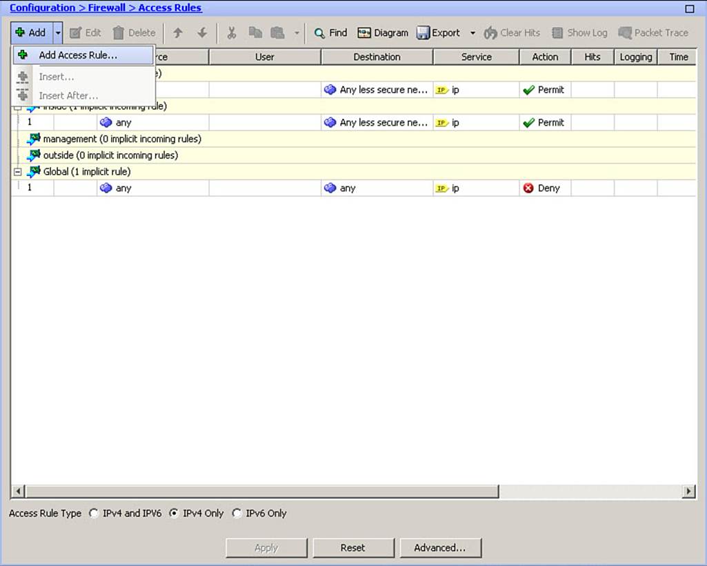
Figure 8-7. Add Access Rule Menu
From the menu, click Add Access Rule. The Add Access Rule dialog box opens, as shown in Figure 8-8.
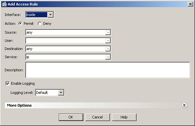
Figure 8-8. Add Access Rule Dialog Box
Because this rule will be implemented on the inside interface, first choose the inside interface from the Interface drop-down list, as shown in Figure 8-8. Next, choose the action to be applied to matching packets by clicking either the Permit or Deny radio button. In the figure, Permit is selected.
In the Source field, you can enter an IP address or click the ellipsis (...) button to choose from a list of addresses and objects known to ASDM (as explained in Chapter 7). Because the inside network is known to ASDM, click the ellipsis button to open the Browse Source dialog box, which is shown in Figure 8-9.
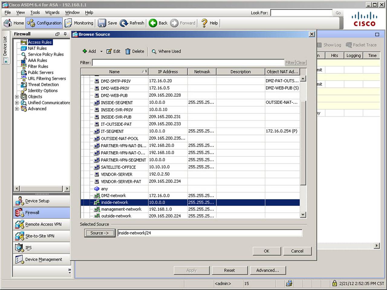
Figure 8-9. Browse Source Dialog Box
There are actually two objects in this list, which both refer to the inside network: INSIDE-SEGMENT and inside-network. Either could be used for the purposes of creating this rule. To demonstrate the differences in resulting syntax, as shown in Figure 8-9, select the inside-network object and then, to choose it as the source, click the Source -> button, so that inside-network/24 appears in the field at the bottom of the dialog box. Then, click OK to finalize the choice.
The scenario is to allow access to any destination on a less secure interface, so leave the keyword any in the Destination field of the Add Access Rule dialog box (refer to Figure 8-8). To specify HTTP as the destination service, click the ellipsis button to the right of the Service field. The Browse Service dialog box opens, as shown in Figure 8-10.
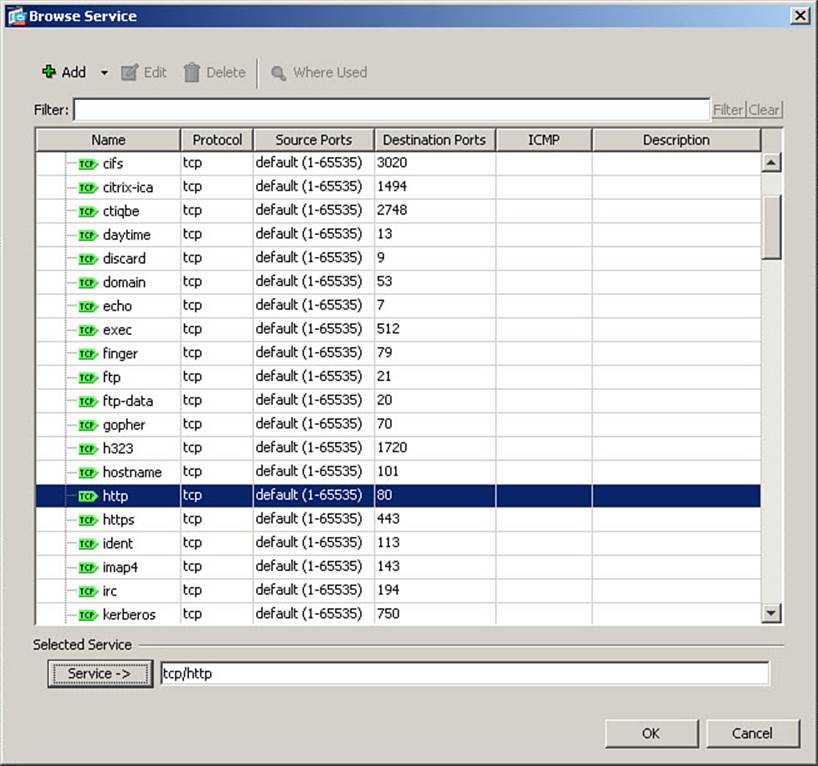
Figure 8-10. Browse Service Dialog Box
The predefined services listed in the Browse Service dialog box are organized first by protocol (TCP, UDP, TCP&UDP, IP, and so on) and then alphabetically within the protocol. In Figure 8-10, the TCP/HTTP service is selected. First, select the desired service, and then click the Service ->button at the bottom of the dialog box, so the selected service(s) appear in the field. Finalize the choice by clicking OK.
Figure 8-11 shows the rule as just configured.

Figure 8-11. Inside Interface Completed Access Rule
Other options are explored later in this chapter. For now, complete the addition of this new access rule by clicking OK. The rule definition is complete, and you are returned to the Access Rules window. Figure 8-12 shows the newly created access rule in the Access Rules window.
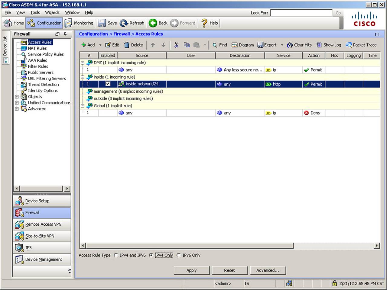
Figure 8-12. Access Rules Table with New Entry
Note that the addition of an explicit permit entry has caused the removal from the inside interface of the implicit permit any to lower-security interface rule. This is very important, as all access that was previously implicitly permitted will now be denied, unless explicit permit entries are added to the inside interface access rules. Remember, it is only in the complete absence of an interface access rule set that traffic is implicitly permitted from higher-security to lower-security interfaces. The moment an explicit rule is defined, the implicit permit will no longer exist, but the implicit deny all from the global ACL remains. Therefore, it is important to apply your entire rule set at the same time, to avoid disruptions in service. The example here is highly simplistic, and only for educational purposes. It would not likely be a realistic policy to apply to the inside interface of an ASA in a production network.
Access Rule Logging
By default, the Cisco ASA logs all security events. When an access rule denies traffic, this is a security event, and the ASA generates syslog message 106023 for each denied packet. Severity level is dependent on which type of packet is denied. A separate log message for each denied flow setup attempt can quickly become burdensome if even a small attack is launched against the networks protected by the ASA.
Although it is possible to disable logging entirely for an access rule, and this might be permissible for permit entries (which sometimes are logged only for troubleshooting purposes), logging should never be disabled for deny rules, as they indicate a security event.
It is therefore recommended that you consider altering the default logging settings for your access rules and setting them to use system message ID 106100 instead. This message ID provides statistics for each access rule, but also lets you limit the number of system messages produced and how often they are reported.
The Cisco ASA generates syslog message 106100 for every matching permit or deny access rule flow that passes through the ASA, and is explicitly configured to generate interval logging messages, instead of the default of one message per “hit.” The first match flow is cached. Subsequent matches increase the hit count for the access rule, rather than creating new syslog messages. If the number of hits is not zero, new 106100 messages are generated at an interval you specify.
When you add an access rule in Cisco ASDM, the Enable Logging check box is checked by default, and the word “Default” is displayed as the selected logging level in the Logging Level drop-down list. These default settings will lead to syslog message 106023 being generated when an IP packet is denied by the access rule.
To enable logging via syslog message 106100 instead of message 106023, you must choose an option other than Default from the Logging Level drop-down list. The choices are the standard syslog levels 0–7 (Emergencies through Debugging). When this is done, and a reporting interval is defined (the default is every 300 seconds), the ASA will generate the 106100 messages at the selected level and report them at the selected interval.
The scenario describes a requirement to log all denied flows on the outside interface. You want to use syslog message 106100 at intervals to avoid excessive log messages; however, it is not possible to edit the definition of the implicit deny all rule in the global ACL. Therefore, to meet this requirement, you need to add an explicit deny all rule on the outside interface, so that you can alter the selected logging level and define a logging interval. You will also enter a description for this rule to explain why you are including it in the access rules.
To begin, from the Access Rules window, choose to add a new access rule, as before. The Add Access Rule dialog box opens. Figure 8-13 shows the rule configuration.
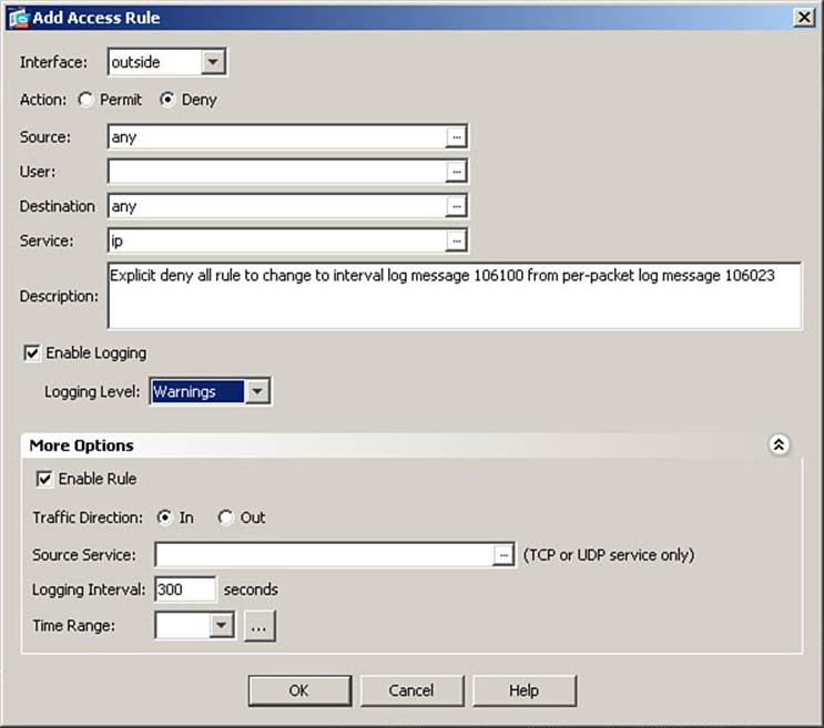
Figure 8-13. Altered Logging and Description in an Access Rule
To create an explicit deny all entry on the outside interface, choose the outside interface from the Interface drop-down list. Then, click the Deny radio button as the Action, leave the keyword any in both the Source and Destination fields, and enter ip in the Service field. These options are configured as described in Figure 8-13.
Next, you want to add a description, explaining why you are creating an explicit deny all rule, when the implicit deny all rule already exists. Figure 8-13 shows the Description field containing an explanation about the use of syslog message 106100.
Note
Entering a description for an access rule will cause the creation of a separate access-list remark entry (access rule), with its own line number, when viewing the access list (rule set) from the CLI. Although this is useful documentation, it should be used judiciously to avoid the creation of overly large access lists. Therefore, use it when creating a rule that is in some way unusual or in need of explanation, but not for rules whose purpose or reason is already clear.
Click the More Options arrow to expand the access rule options area. Note when you do that the Logging Interval field is dimmed and thus cannot be edited.
As explained previously, to alter logging to the use of syslog message 106100, you must choose a specific level in the Logging Level field, rather than leaving it at the default. As shown in Figure 8-13, change the setting in this field to Warnings (4) as the desired level. When this is done, the Logging Interval field in the More Options area becomes editable. Enter an appropriate interval, from 1 to 600 seconds, in this field. Figure 8-13 shows an entry of 300 seconds, which is the default. Finally, click OK to complete the addition of this new access rule.
The next requirement in the scenario is to permit access from any source on the outside interface to the DMZ web server, using HTTP. This rule needs to be added before the explicit deny all rule just configured. If you were to use the Add Access Rule function, as previously, the new rule defined would end up below other existing rules, and above only the implicit deny all rule from the global ACL.
The menu contains options to Insert (with a + sign above a line, meaning the new rule will be inserted above the currently selected rule) or Insert After (with the + sign below a line, meaning the new rule will be inserted below the currently selected rule). Choose the Insert option to open the Insert Access Rule dialog box, as shown in Figure 8-14.
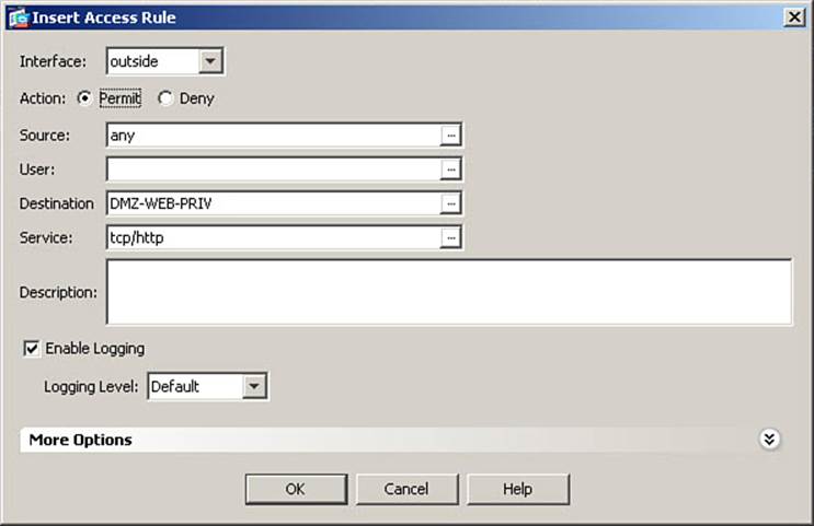
Figure 8-14. Inserting a Permit Web Server Access Rule
Figure 8-14 shows the choice of the outside interface, permit as an action, and any as a source address. When you permit access from the outside world, “any” is frequently the source address. Next, you must specify the DMZ web server as the destination. This server has the configured IP address of 172.16.0.5 and was previously defined as the network object DMZ-WEB-PRIV. With OS versions 8.3 and higher, all access rules, on all interfaces, whether applied inbound or outbound, refer to the native addresses of hosts or networks. Therefore, you can enter this IP, or the object name, as the destination in this access rule.
Recall, however, the discussion of address translation in Chapter 7, and its effect on interface access rules, if using OS versions 8.2 or earlier. With those OS versions, when an access rule is applied inbound on an interface, the access rule condition is checked before address translation occurs. Thus, when configuring access rules that permit traffic from a less secure interface to reach a destination on a more secure interface, you must use a destination address of the global (translated) IP address of the destination host, not its local (untranslated) IP address. The DMZ web server had a global IP address of 209.165.200.228 assigned to it, so if using earlier OS versions, you need to enter that address in the Destination field.
This fact means that access rule configuration is now much simpler with OS versions 8.3 and higher, because you do not need to remember address translation rules (which are frequently different on different interfaces) to properly configure access rules.
Therefore, to configure this access rule, click the ellipsis (...) button for the Destination field and, using procedures already demonstrated, select the object name DMZ-WEBPRIV and assign it as the destination address for this rule. This assignment is reflected in Figure 8-14.
Note
If entering IP addresses directly in either the Source or Destination field, it is not necessary to enter the /32 after the address to indicate a host-specific netmask, if you want to define an individual host. If no netmask value is specified, ASDM defaults to a host-specific mask when creating access rules.
Next, specify the destination service, as previously demonstrated. Figure 8-14 shows TCP/HTTP as the configured service. Optionally, enter a description. Because the purpose of this rule is readily apparent, no description is shown in Figure 8-14. Finalize the insertion of this access rule by clicking OK.
The final access rule in the scenario is to permit the DMZ SMTP server to reach any host through any interface, using SMTP.
Note
Although this example serves to demonstrate how the destination of “any” will apply to both higher- and lower-security interfaces as destinations, a more appropriate configuration for a production network is shown later in the chapter, in the section, “Managing Access Rules from the CLI.”
Because this will be the initial rule on the DMZ interface, go through the steps to add a new access rule, as previously described. Figure 8-15 shows the Add Access Rule dialog box, where the new rule is configured.
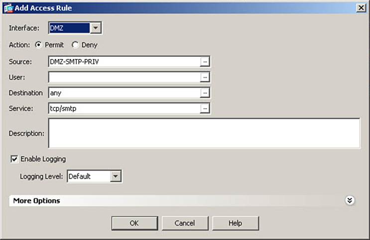
Figure 8-15. Adding an Access Rule to the DMZ Interface
As shown in Figure 8-15, first choose DMZ from the Interface drop-down list as the interface where the rule will be applied, and then click the Permit radio button as the Action. Using procedures previously demonstrated, select the network object DMZ-SMTP-PRIV in the Source field.
The SMTP server needs to be able to reach other SMTP servers on any other ASA interface, whether more secure or less secure. Therefore, Figure 8-15 shows leaving the keyword any in the Destination field (notice that “any” does not mean “the Internet”). Specifying services and entering descriptions has already been explained. The figure shows TCP/SMTP as the selected service. Finalize the rule configuration by clicking OK.
Configuring the Global ACL
Because all interface access rule sets now contain explicit entries, it is possible to enter explicit rules in the global ACL, without adversely impacting functionality by “silently” removing implicit rules from other interface rule sets.
This configuration scenario is based on the decision to use NTP for time synchronization throughout your network. You have decided to use the National Institute of Standards and Technology (NIST) publicly available NTP server. You want any host, on any interface, to be able to reach this time server for synchronization.
As previously mentioned, the creation of rules in the global ACL is performed in the same manner as the creation of any access rule. Therefore, from the Access Rules window, select to add a new access rule. Figure 8-16 shows the Add Access Rule window where this new rule is defined.
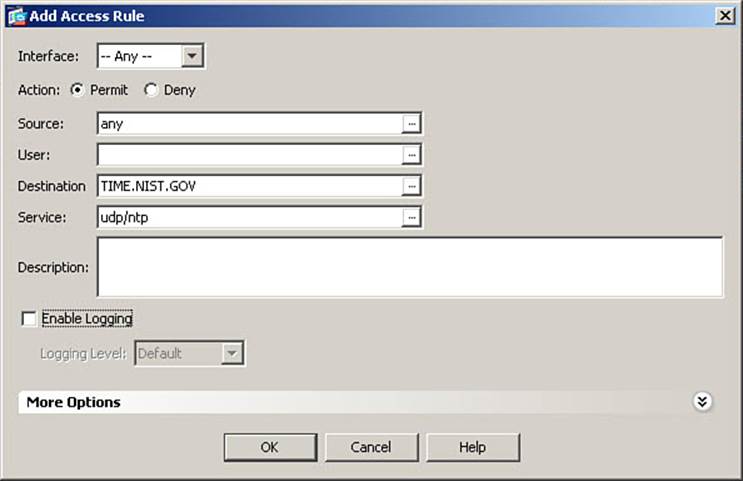
Figure 8-16. Configuring a Global Access Rule
To insert a rule in the global ACL, set the Interface to Any, rather than a specific interface name, as shown in Figure 8-16.
Because this rule will be applied to any interface, leave the source address set to any. Then, using procedures previously demonstrated, create a new network object named TIME.NIST.GOV, defined as the host IP 192.43.244.18, and assign it as the destination address. Using procedures previously demonstrated, assign UDP/NTP as the service. Finally, because this is a permit access rule for traffic that is not significant to track, uncheck the Enable Logging check box to disable logging for this specific rule. All these settings are shown in Figure 8-16.
Click OK to complete the addition of the global ACL rule. Figure 8-17 shows the Access Rules window, including all the newly created rules.

Figure 8-17. Access Rules Table with New Rules
Finally, click Apply to send all changes made thus far to the ASA.
The CLI commands generated by the changes made are as follows. The access list names are altered from what ASDM would assign (spacing has been added for readability):
object network TIME.NIST.GOV
host 192.43.244.18
!
access-list INSIDE-IN line 1 extended permit tcp 10.0.0.0 255.255.255.0 any eq http
!
access-list DMZ-IN line 1 extended permit tcp object DMZ-SMTP-PRIV any eq smtp
!
access-list OUTSIDE-IN line 1 extended permit tcp any object DMZ-WEB-PRIV eq http
access-list OUTSIDE-IN line 2 remark Explicit deny all rule to change to interval
log message 106100 from per-packet log message 106023
access-list OUTSIDE-IN line 3 extended deny ip any any log 4 interval 300
!
access-list GLOBAL-ACL line 1 extended permit udp any object TIME.NIST.GOV eq ntp
log disable
!
access-group DMZ-IN in interface DMZ
access-group INSIDE-IN in interface inside
access-group OUTSIDE-IN in interface outside
access-group GLOBAL-ACL global
If you are configuring the ASA from the CLI, you can enter these commands in global configuration mode.
Access-list commands define access rules, and the CLI access-group command applies access rules to interfaces. The access-group command, which applies the global ACL contains neither a direction nor an interface name, but simply the keyword global. Despite the lack of a directional indicator, the global ACL is applied only in the inbound direction on all interfaces.
Note the syntax in the INSIDE-IN ACL refers to the IP network 10.0.0.0 with mask. This is because the example selected the inside-network as the source. If you had instead selected the object INSIDE-SEGMENT, as objects were used in the other rules, the access list would have instead appeared as follows. The use of objects makes the purpose and meaning of the rules much clearer, assuming a good naming convention is used:
access-list INSIDE-IN line 1 extended permit tcp object INSIDE-SEGMENT any eq http
Cisco ASDM Public Server Wizard
It has been explained that allowing access to a server from a lower security interface (when the server is located on a network connected to a higher security interface) requires both the creation of a static translation and an interface access rule on the lower-security interface, to allow the session to be established.
Cisco ASDM contains a feature, called the Public Server Wizard, which creates a static NAT rule for a specified host, as well as an interface access rule for that host using a particular service, by completing information on a single screen within ASDM. The commands generated are those that have already been covered separately, but this wizard consolidates those separate configuration steps into one, thus reducing the complexity involved in separately configuring the required parameters.
For this example, assume a new web server is being configured, which will be located in the DMZ segment. Translation and access rules will be created using the ASDM Public Server Wizard. Also, to demonstrate alternative naming methods, a different object naming method will be used for the translation objects.
To begin, navigate to Configuration > Firewall > Public Servers, and then click the Add button in the Public Servers window. The Add Public Server dialog box opens. Figure 8-18 shows the rule configuration.
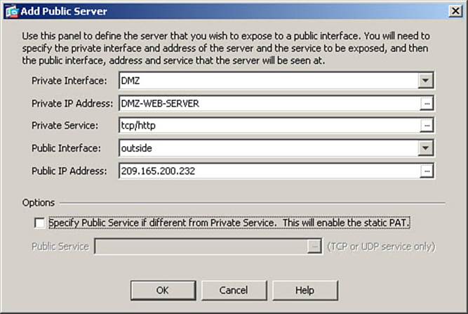
Figure 8-18. Using the ASDM Public Server Wizard
As shown in Figure 8-18, complete the fields with the necessary information. In the Private Interface field, select the interface through which the actual server is reachable—in this case, DMZ. Next, using procedures previously demonstrated in Chapter 7, click the ellipsis button for the Private IP Address field, and create a new network object named DMZ-WEB-SERVER, defined as the host address 172.16.0.23. Do not define any NAT rules when creating the object. In the Service field, enter (or choose by clicking the ellipsis button to open a list) the service (port) on which the server is to be reachable from the less secure interface—in this case, TCP/HTTP. For public interface, select outside. Finally, in the Public IP Address field, directly enter the IP address 209.165.200.232.
Note
Because translations no longer have an impact on addresses used in access rules, AAA rules, MPF, and so on, this example does not create a –PRIV and –PUB object for the server, as was done in Chapter 7 examples. The public address appears in the ASA configuration only once—in the NAT command, so the network object for the server is simply the server name, with no indication of the fact that it is defining the private address. Similarly, the translated address is entered, with no indication of what server it refers to, because the server object name will appear as part of the same nat command.
Finalize the rule configuration by clicking OK. Finally, click Apply to send the changes to the ASA.
The CLI commands generated by the changes made are as follows:
object network DMZ-WEB-SERVER
host 172.16.0.23
object network DMZ-WEB-SERVER
nat (DMZ,outside) static 209.165.200.232
access-list OUTSIDE-IN line 1 extended permit tcp any object DMZ-WEB-SERVER eq http
If you are configuring the ASA from the CLI, you can enter these commands directly in global configuration mode. Note that the Public Server Wizard created the new access rule in position number 1 in the list of rules applied to the selected public interface (outside in this example). If this is not the desired location, reorder to access rules as described later, in the section, “Managing Rules in Cisco ASDM.”
Configuring Access Control Lists from the CLI
You configure interface access rules in the CLI by creating access control lists (ACL) using the access-list command to configure individual rules. ACLs are made up of one or more access control entries (ACE), each represented by one line in the ACL, that specify a permit or deny rule, or remark.
Note
An ACE in an ACL is the equivalent of an interface access rule in the Cisco ASDM Access Rules table.
If you are configuring access control lists from the CLI, Cisco ASA ACLs use network masks, and not the wildcard masks used in Cisco router ACLs, whenever masks are specified. The keywords any and host work in ASA access rules as they do in other Cisco ACLs.
After an ACL is configured, it must be activated and applied to an interface using the CLI access-group command. This command specifies which ACL is being applied, to which interface, and in which direction (inbound or outbound). The command specifies the keyword in or out to specify the direction in which traffic is flowing through the interface, where the ACL is to be applied. Only one ACL can be applied to an interface, per direction. So, you could have one ACL applied inbound and another applied outbound on the same interface, but you could not apply two different ACLs inbound on the same interface.
Note
When an access rule is configured using Cisco ASDM, it creates both the access-list and access-group commands in the ASA configuration.
If you create a remark in an ACL for documentation purposes, you can place it before or after the ACE to which it refers. You should, however, place remarks consistently so that it is clear to which ACE remarks are referring. When an access rule remark is configured using Cisco ASDM, it is always placed above the access rule to which it refers, so this is probably the best choice in order to maintain consistency in an environment where administrators use both ASDM and the CLI to manage the ASA.
When you are creating ACLs from the CLI, entering line numbers and the keyword extended is optional. Line numbers are automatically assigned to all ACEs in order, one number at a time (you cannot specify an interval, as you can on Cisco routers, when renumbering ACLs). Also, remember that all access lists are assumed to be extended (have the ability to specify protocol and both source and destination addresses and ports), unless you specify they are standard ACLs. Although standard ACLs do exist on an ASA, they are used for things such as route update filters or VPN split-tunneling definitions, and cannot be used for interface access rules. Full syntax options are presented in the “Command Reference to Check Your Memory” section at the end of this chapter.
Implementation Guidelines
When implementing interface access rules to provide access control, consider the following implementation guidelines:
• Consider applying interface access rules to all ASA interfaces and permitting only the minimal required set of services. This is in keeping with a minimal access policy, which is both effective for preventing network attacks and required by some regulatory standards. Some organizations might configure a less stringent access methodology, to increase manageability, if the number of rules would otherwise become cumbersome. This approach generally will increase the risk of attack against protected networks.
• Generally, the simplest strategy to implement effective access control is to use only inbound interface access rules (applied as packets ingress the ASA through an interface) that are applied to all ASA interfaces. This guarantees that every connection always passes through one, and only one, set of interface access rules as it crosses the ASA. It also prevents rule duplication on multiple interfaces. If a rule is required on multiple interfaces, consider whether it is appropriate to make it a global access rule.
• As with any sequential rule set, you should place your most specific rules (for example, specific to host 10.0.0.5 vs. network 10.0.0.0/24) toward the top of the rule set, to avoid overriding them with more general rules. Also, as long as more specific rules are not overridden, you should also consider placing rules that you anticipate will be matched most frequently toward the top of the rule set, to minimize required processing.
• In all interface access rules, it is recommended that you add an explicit deny all statement at the end of the rule set, to gather statistics on denied traffic and to be able to observe how many connection attempts are being denied by this explicit catch-all rule (the hit count). You may or may not follow this recommendation, depending on you use of the global ACL.
Time-Based Access Rules
In some instances, entering a permanent access rule is inappropriate, and you’ll want more granular control over when a rule is enforced and what it enforces. Examples include access rules for contract workers, who have a defined end date and time to their access privileges, access rules for applications that function only during specific time frames, and access rules for corporate environments with multiple shifts of workers, each with unique access permissions. The Cisco ASA accommodates these needs by offering time-based access rules.
You can define absolute and/or recurring time ranges. An example of an absolute time range would be July 1, 2012 at midnight through September 31, 2012 at 11:59 p.m. An example of a recurring time range would be weekdays (M–F), from 8:00 a.m. to 5:00 p.m.
Note
If a time-range command has both absolute and periodic values specified, then the periodic commands are evaluated only after the absolute start time is reached, and are not further evaluated after the absolute end time is reached. For example, if both the time ranges mentioned in the preceding paragraph are defined within a single time range definition, then applied to an ACE, the rule would be active only from July 1, 2012 to September 31, 2012, and within that time range, only on weekdays between 8 a.m. and 5 p.m.
To the configuration scenario, the following two requirements have been added:
• Permit a contractor FTP access to the DMZ web server, beginning April 1, 2012 and expiring June 30, 2012, for the purpose of updating content, and log all access.
• Allow regional offices in the United States to post files to/pull files from the DMZ FTP server on weekdays, from midnight until 4:59 a.m. local time.
Note
Time ranges are enforced based on what time it is at the ASA’s location, not based on the time at the source of a connection. Keep this in mind if configuring an ASA for an organization with users distributed across multiple time zones.
Configuring time-based access rules is a two-step process:
Step 1. Configure an absolute and/or recurring time range.
Step 2. Configure an access rule and reference a defined time range for this rule. Thus, the rule is active only during the defined time range. At all other times, it is present in the configuration, but inactive. Initial packets of a flow are evaluated by time-based access rules only while those rules are active.
To configure a time range, navigate to Configuration > Firewall > Objects > Time Ranges. The Time Ranges window is displayed. This list is initially blank. To create the first time range, for contractor access, click Add to open the Add Time Range dialog box, shown in Figure 8-19.
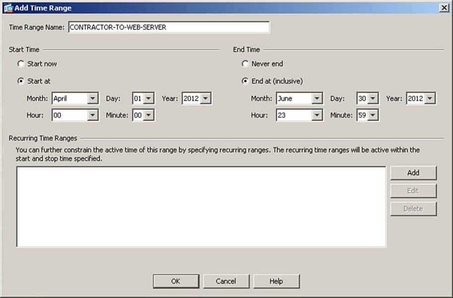
Figure 8-19. Configuring an Absolute Time Range
First, give the time range a name. Figure 8-19 shows a name of CONTRACTOR-TO-WEB-SERVER entered.
Note
Spaces are not allowed in time range names.
To define an absolute time range, enter information in both the Start Time and End Time areas. Figure 8-19 shows a Start At value of April 1, 2012 at 00:00 (midnight), and an End At (Inclusive) value of June 30, 2012 at 23:59 (11:59 p.m.). Remember that midnight is the beginning of a day, not the end, so this time range runs from April 1 through June 30, including all 24 hours of both those days. Finalize the definition of this absolute time range by clicking OK.
The next required time range is for the purpose of allowing remote offices to access the DMZ FTP server on weekdays from midnight to 4:59 a.m. This is an ongoing requirement, with no beginning or ending dates, so a recurring time range is the proper choice.
To define a recurring time range, navigate to the Time Ranges window as before, and click Add to open the Add Time Range dialog box once again, as shown in Figure 8-20.
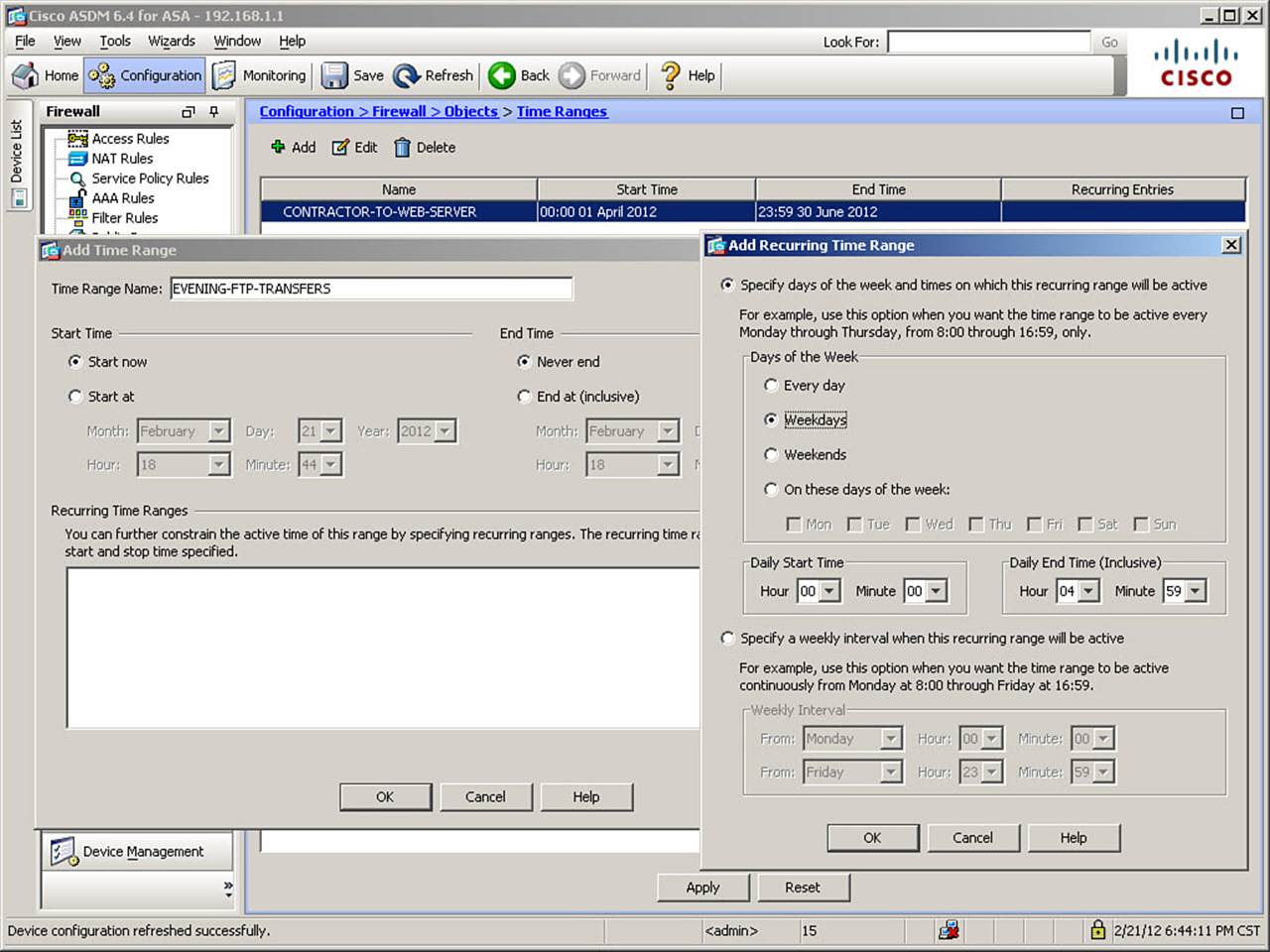
Figure 8-20. Configuring a Recurring Time Range
Enter a name for the time range as before. Figure 8-20 shows a name of EVENING-FTP-TRANSFERS entered. For recurring time ranges, select the Start Now radio button under Start Time, and select the Never End radio button under End Time. Then, at the right side of the Recurring Time Ranges area, click the Add button to open the Add Recurring Time Range dialog box, which is shown in the right side of Figure 8-20.
When defining a recurring time range, you might choose to either specify days of the week and times when the range is active (for instance, weekdays from 8 a.m. to 5 p.m.) or specify a weekly interval (such as Monday at 8 a.m. through Friday at 5 p.m.). Note that these are very different choices, although they both have the same beginning and ending times.
The configuration example requires daily time ranges, so Figure 8-20 shows that option chosen. Next, define the specific daily time range. In the figure, Weekdays is chosen for the Days of the Week parameter. Then, specify the Daily Start Time and Daily End Time (Inclusive). Figure 8-20shows a Daily Start Time of 00:00 and a Daily End Time of 04:59. Click OK to complete the definition of the daily time range, and then click OK again to complete the definition of the recurring time range.
Now that the necessary time ranges have been defined, it is time to create the time-based access rules that refer to them. Navigate to the Access Rules window as before. Specify that you will be inserting the time-based access rule above the explicit deny all rule on the outside interface, as before. Figure 8-21 shows the Insert Access Rule dialog box, where the contractor access rule is defined.
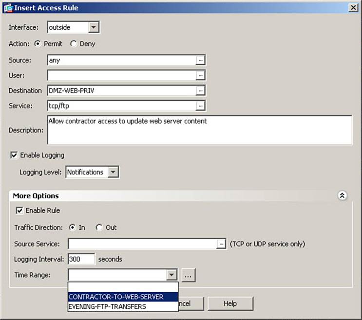
Figure 8-21. Configuring a Time-Based Access Rule
Figure 8-21 shows the choice of the outside interface, permit as the action, and a source of any, because you cannot predict the contractor’s IP address in advance. Do not worry that this would appear to let anyone in the world access the web server using FTP. The server itself will enforce login credentials, to ensure only authorized access.
Click the ellipsis button for the Destination Address field. Select and assign the network object DMZ-WEB-PRIV as the destination. Then, specify TCP/FTP as the destination service, as previously demonstrated. Optionally, enter a description to create a remark ACE. Figure 8-21 shows the specified changes.
Because the stated requirement includes the logging of all access, verify that the Enable Logging check box is checked (it is by default). Set the Logging Level and Logging Interval, if desired. Figure 8-21 shows a Logging Level of Notifications (5) and the default Logging Interval of 300 seconds.
To make this access rule time-based, at the bottom of the More Options area, click the drop-down arrow next to Time Range and choose the time range defined for the contractor access rule. Figure 8-21 shows this time range being chosen. Finalize the configuration of this time-based access rule by clicking OK.
Using the same procedures, insert a rule above the explicit deny all rule in the outside interface rule set, which allows access from any source IP address to the network object DMZ-FTP-PRIV using the TCP/FTP service. Use default logging settings and apply the time range named EVENING-FTP-TRANSFERS.
Figure 8-22 shows the complete Access Rules table, containing all rules created thus far.
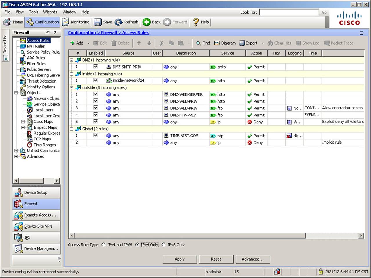
Figure 8-22. Completed Access Rules Table
Note that the Hits field is automatically updated to show the number of times an initial packet in a flow has matched a particular access rule. Only the initial packet in a flow matches a rule and causes the hit counter to increment—traffic does not match a rule on a per-packet basis.
Click Apply to send the changes to the ASA.
The CLI commands generated by the changes made are as follows (spacing inserted for readability):
time-range CONTRACTOR-TO-WEB-SERVER
absolute start 00:00 01 April 2012 end 23:59 30 June 2012
!
time-range EVENING-FTP-TRANSFERS
periodic weekdays 00:00 to 04:59
!
access-list OUTSIDE-IN line 3 remark Allow contractor access to update web server
content
access-list OUTSIDE-IN line 4 extended permit tcp any object DMZ-WEB-PRIV eq ftp
log 5 interval 300 time-range CONTRACTOR-TO-WEB-SERVER
access-list OUTSIDE-IN line 5 extended permit tcp any object DMZ-FTP-PRIV eq ftp
time-range EVENING-FTP-TRANSFERS
If you are configuring the ASA from the CLI, you can enter these commands directly, beginning in global configuration mode.
Configuring Time Ranges from the CLI
To configure a time range in the CLI, use the time-range command, followed by the range name, to enter time range configuration mode. Use the keyword absolute or periodic to define the type of time range being configured. To specify a time-based condition within an ACE, simply append the keyword time-range and the range name at the end of the rule definition. Full syntax options are presented in the section, “Command Reference to Check Your Memory,” at the end of this chapter.
Verifying Interface Access Rules
Use the show access-list command to view configured ACLs. The show access-list command displays all configured ACLs, the ACEs within each ACL, hit counts for each ACE, and a unique hexadecimal identifier for each ACE (the identifiers are system-created and not configurable). By contrast, the show running-config access-list command shows only the configured ACLs, without expanding object-groups, showing hit counts, and so on.
To know whether time-based ACEs should be active, use the show clock command to display the current time, according to the ASA. Remember that it is the ASA clock that determines whether time-based access rules are active, not the time where the user is located.
Example 8-6 shows the use of the show clock command to verify ASA time.
Example 8-6. show clock Command Usage
FIREWALL# show clock
10:22:38.829 CST Sat Feb 18 2012
Example 8-7 shows the use of the show access-list command, using the argument of an ACL name to limit the output to only that ACL, rather than all ACLs. (Spacing has been inserted between each ACE to enhance readability.)
Example 8-7. show access-list Command Output
FIREWALL# show access-list OUTSIDE-IN
access-list OUTSIDE-IN; 5 elements; name hash: 0x9ccc1a31
access-list OUTSIDE-IN line 1 extended permit tcp any object DMZ-WEB-SERVER eq www
(hitcnt=8) 0x40178d02
access-list OUTSIDE-IN line 1 extended permit tcp any host 172.16.0.23 eq www
(hitcnt=8) 0x40178d02
access-list OUTSIDE-IN line 2 extended permit tcp any object DMZ-WEB-PRIV eq www
(hitcnt=4571) 0xccb8bc5d
access-list OUTSIDE-IN line 2 extended permit tcp any host 172.16.0.5 eq www
(hitcnt=4571) 0xccb8bc5d
access-list OUTSIDE-IN line 3 remark Allow contractor access to update web server
content
access-list OUTSIDE-IN line 4 extended permit tcp any object DMZ-WEB-PRIV eq ftp log
notifications interval 300 time-range CONTRACTOR-TO-WEB-SERVER (hitcnt=0)
(inactive) 0xcef8e373
access-list OUTSIDE-IN line 4 extended permit tcp any host 172.16.0.5 eq ftp log
notifications interval 300 time-range CONTRACTOR-TO-WEB-SERVER (hitcnt=0)
(inactive) 0xcef8e373
access-list OUTSIDE-IN line 5 extended permit tcp any object DMZ-FTP-PRIV eq ftp
time-range EVENING-FTP-TRANSFERS (hitcnt=92) (inactive) 0xf40023a7
access-list OUTSIDE-IN line 5 extended permit tcp any host 172.16.0.10 eq ftp time-
range EVENING-FTP-TRANSFERS (hitcnt=92) (inactive) 0xf40023a7
access-list OUTSIDE-IN line 6 remark Explicit deny all rule to change to interval log
message 106100 from per-packet log message 106023
access-list OUTSIDE-IN line 7 extended deny ip any any log warnings interval 300
(hitcnt=11244) 0x502c4bfb
Notice that neither of the time-based access rules is currently active—the contractor rule because the defined time period for that rule has not yet begun, and the file transfer rule because it is a Saturday, and would be outside the defined time range even on a weekday.
When using the show access-list command (but not when using the show running-config access-list command), access list entries that contain an object or object group name will be “expanded” to show the IP addresses involved on individual lines, with the same line number as the entry containing the object or object group name. Note the indented items under each line containing an object name in Example 8-7, showing the IP addresses associated with those network objects.
The commands in Example 8-7 are listed by ACL line number. The line numbers displayed in the show access-list output are optional when you are configuring an ACL from the CLI. If you do not specify a line number when entering an access-list command, it will be assigned by the system, and the line will be placed at the end of the ACL. Each ACE (including remarks) will be given a unique line number within the ACL. By specifying a line number when you are defining an ACE from the CLI, it is possible to insert an ACE at a specific position in an ACL (which is covered in the section, “Managing Access Rules from the CLI”).
If you only want to see the identifier (name or number) of all the ACLs configured on your ASA, along with the number of ACEs they contain and their name hash (a non-configurable internal value for tracking the ACL), use the show access-list brief command. Example 8-8 shows the usage of this command, which specifies two access list names as arguments to limit output to only those ACLs.
Example 8-8. show access-list brief Command Output
FIREWALL# show access-list INSIDE-IN OUTSIDE-IN brief
access-list INSIDE-IN; 1 elements; name hash: 0xf1656621
access-list OUTSIDE-IN; 5 elements; name hash: 0x9ccc1a31
Managing Rules in Cisco ASDM
The Cisco ASDM Access Rules table contains several features that enable you to quickly and efficiently manage it. Figure 8-23 shows the Access Rules table after a specific rule has been right-clicked to open the options menu.
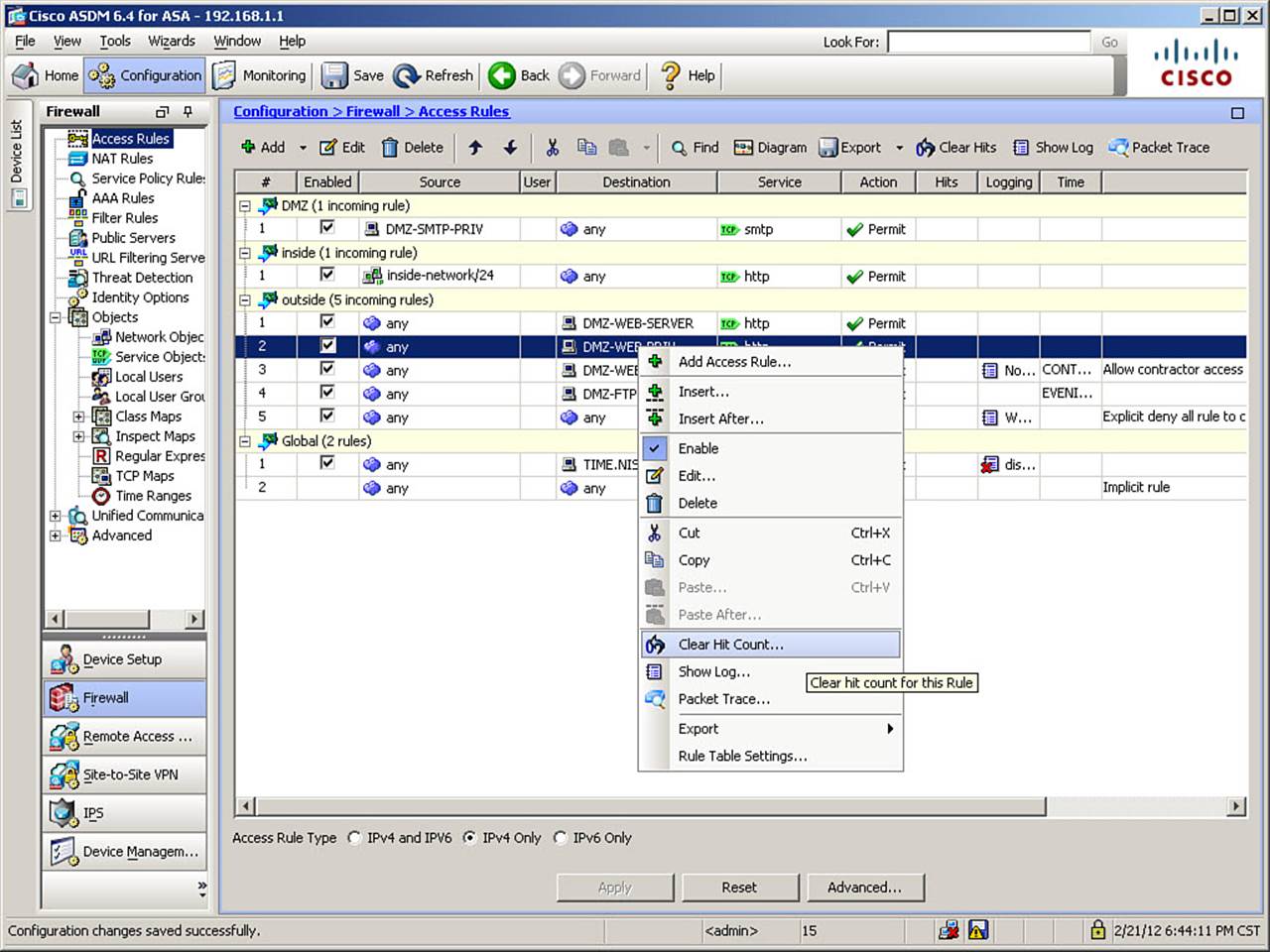
Figure 8-23. Managing Access Rules in ASDM
Notice that from this menu, you can choose to add an access rule or insert access rules (previously demonstrated using the Add button at the top of the window), or edit or delete a rule (also available through buttons at the top of the window). You can also easily copy (clone) a rule, for instance, when you add another web server—just clone the existing web server rule, and then edit it to change the destination address.
You can change the order of rules, using either the Cut, Copy, and Paste (or Paste After) options or the Move Up and Move Down arrows (to the right of the Delete button at the top of the window). Remember that because access rules are evaluated in order, positioning within the rule set applied to an interface can be critical to functionality.
From within ASDM, you can also clear the hit counter for a specific rule (right-click menu) or all access rules (button on the toolbar), which is commonly required during troubleshooting. You can also show log messages generated by a chosen rule (right-click menu) or by all access rules (button on the toolbar). Additionally from the right-click menu, you can export the contents of the Access Rules table to a comma-separated value (CSV) format file.
You can edit a rule in place (rather than opening the Edit Access Rule dialog box) by clicking in a field such as Source or Destination and altering the contents within the Access Rules window. Rules can also be temporarily disabled (if you want to permanently remove a rule, simply delete it).Figure 8-24 shows such an example. The DMZ web server is going to be undergoing maintenance, so you want to temporarily disable the rule that permits access to the server.
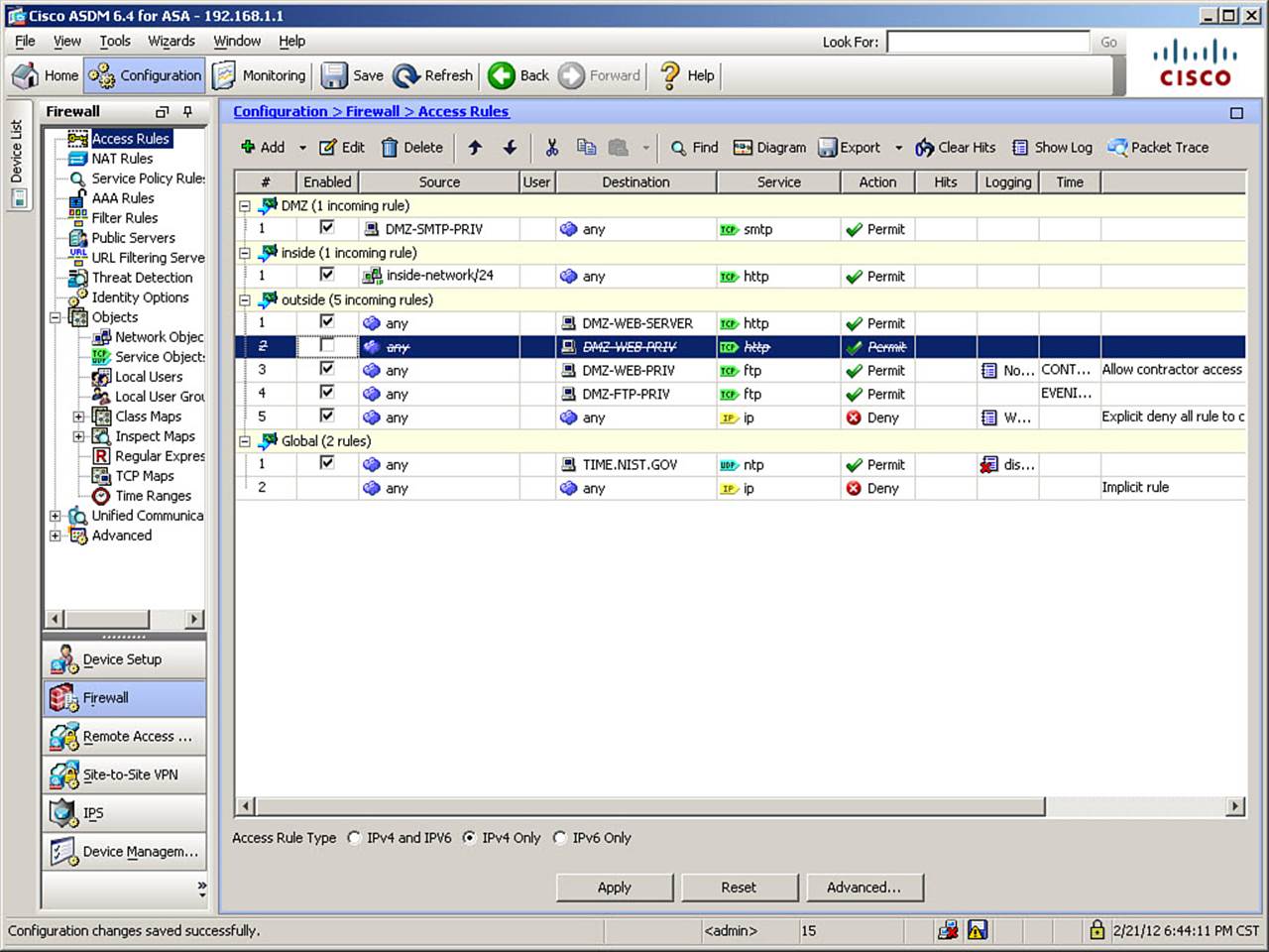
Figure 8-24. Temporarily Disabling an Access Rule
Figure 8-24 shows the access rule that permits access to the web server selected (highlighted). To temporarily disable the rule, simply uncheck the Enabled check box and click Apply. Note that several of the columns are “crossed out” graphically when a rule is disabled in this way, as shown in Figure 8-24. When the maintenance on the web server is complete, re-enable the rule by checking the Enabled check box and clicking Apply.
The CLI command generated by the changes made is as follows:
access-list OUTSIDE-IN line 2 extended permit tcp any object DMZ-WEB-PRIV eq http
inactive
If you are configuring the ASA from the CLI, you can enter this command directly in global configuration mode. Note that you are simply appending the keyword inactive to the existing ACE.
Another helpful feature within ASDM is the display of a diagram to visually represent the function of an access rule. The Diagram feature is a toggle; click the Diagram button in the toolbar to enable it, and it will remain on until you click that button again to disable the feature. Figure 8-25shows the altered view of the Access Rules window with the Diagram feature enabled, after having re-enabled the web server access rule.
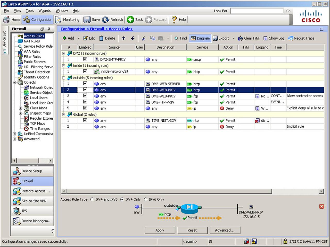
Figure 8-25. Access Rules Diagram Feature Enabled
The Diagram feature causes a visual representation of the selected access rule to display at the bottom of the window. In Figure 8-25, the access rule permitting access to the DMZ web server is selected. The diagram shows that any source can send TCP/HTTP packets into the outside interface of the ASA, and they will be permitted to reach the destination object name of the DMZ web server’s native address.
Managing Access Rules from the CLI
Several commands are available to manage ACLs and their component ACEs from the CLI. To delete an ACE, use the keyword no and specify the complete rule in the CLI (you do not have to include the line number or keyword extended, but the command will still work if you do), as shown in the following command:
FIREWALL(config)# no access-list OUTSIDE-IN permit tcp any object DMZ-WEB-PRIV eq
http
Only the single ACE is deleted, and remaining ACEs are appropriately renumbered. You can delete an entire access list from the configuration by using the clear configure access-list [ACL-name] command, as demonstrated here:
FIREWALL(config)# clear configure access-list INSIDE-IN
The use of this command will also automatically remove the associated access-group command if the ACL was applied to an interface at the time of deletion.
Note
The previous two commands are for purposes of illustration only, and are not accounted for in further configuration examples in this chapter.
Caution
If you delete all entries from an ACL, all references to that ACL are removed from the configuration. This is especially important for access lists used for purposes other than interface access rules. For example, in Chapter 7, translation rules were created that referenced ACLs. If such an ACL were deleted in its entirety, the translation rules that referred to it would be automatically deleted as well. You are not given any warning or acknowledgment message stating that this has occurred.
Furthermore, using the clear configure access-list command without any arguments will delete all ACLs on the ASA, no matter how they were applied. Therefore, exercise great care when using any variation of the clear configure access-list command.
You can insert an ACE at a specific position in an ACL by specifying a line number when configuring the ACE. The ACE will be inserted above the ACE that currently has that line number, and all subsequent ACEs will be renumbered automatically. Consider the following existing ACL:
access-list DMZ-IN line 1 remark Allow mail server to both inside and Internet
access-list DMZ-IN line 2 extended permit tcp object DMZ-SMTP-PRIV any eq smtp
Suppose you want to implement more effective security, while still permitting the SMTP server to reach all required destinations, so you decide to limit SMTP access to the inside network to only the internal mail server. Example 8-9 shows the required configuration, along with a showcommand that verifies the changes. An appropriate object definition is assumed to exist for the internal mail server.
Example 8-9. Inserting ACEs into an Existing ACL
FIREWALL(config)# access-list DMZ-IN line 2 permit tcp object DMZ-SMTP-PRIV object
INSIDE-SMTP-SERVER eq smtp
FIREWALL(config)# access-list DMZ-IN line 3 deny tcp object DMZ-SMTP-PRIV object
INSIDE-SEGMENT eq smtp
FIREWALL(config)# exit
FIREWALL# show running-config access-list DMZ-IN
access-list DMZ-IN line 1 remark Allow mail server to both inside and Internet
access-list DMZ-IN line 2 extended permit tcp object DMZ-SMTP-PRIV object INSIDE-
SMTP-SERVER eq smtp
access-list DMZ-IN line 3 deny tcp host object DMZ-SMTP-PRIV object INSIDE-
SEGMENT eq smtp
access-list DMZ-IN line 4 extended permit tcp object DMZ-SMTP-PRIV any eq smtp
Organizing Access Rules Using Object Groups
The access rules demonstrated thus far have been manageable. When only one source, one destination, and one service exist, only a minimal number of access rules are needed in an interface rule set. However, as the number of clients (sources), servers (destinations), and services increase, the number of access rules required to manage a security policy may increase uncontrollably.
Consider, for example, a situation where a company maintains 50 servers on a DMZ network, which provide four services each to the outside world (perhaps HTTP, HTTPS, FTP, and SMTP), and also act as clients for connections to five database servers in the inside network, on one destination port. Using the methods shown thus far, you would need to create 200 access rules for the outside interface and 5 more for the DMZ interface.
One solution for this dilemma is to group specific hosts into networks and allow entire networks to access resources. You could also allow complete TCP, UDP, or even IP connectivity between hosts. These approaches are not recommended, however, as they depart from the minimal-access approach to network security and increase risk by allowing unnecessary connectivity. What is needed is a way to reduce configuration complexity, while maintaining a minimal access security design.
The solution is object grouping. Object grouping allows you to group arbitrarily into a single access rule, hosts, resources, or services that share the same policy requirements, thereby minimizing the number of rules you must create. Furthermore, adding or removing hosts or services from object groups will automatically add or remove them to or from any access rule that references the object group, thus greatly simplifying ongoing changes to security policy.
For instance, continuing with the example previously stated, you could group the 50 servers in the DMZ into a group named DMZ-SERVERS, group the five database servers on the inside network into a group named DB-SERVERS, and group the four services (HTTP/S, FTP, and SMTP) into a group named PUBLIC-SERVICES. Instead of 205 access rules, you could now implement the same security policy using two access rules. That’s right—a better than 100:1 reduction in access rules, through the use of object groups.
Note
You can also nest object groups, by making one or more object groups members of another object group of the same type. For instance, if you had network object groups for regional offices in the United States and Canada, you could make these two groups members of an object group called NORTH-AMERICAN-OFFICES. The individual groups could be referenced in access rules that apply only to one country or the other, and the nested object group could be referenced in access rules that apply to both.
Creation of object groups is entirely optional, although it should be clear by now why you might want to use them. There are four types of object groups you can create on the ASA:
• Network object groups: These groups consist of any combination of individual host addresses and network addresses, and can be used in the source or destination address fields of ACLs, as well as in the definition of network objects, as demonstrated in Chapter 7.
• Service object groups: These groups consist of any combination of individual ports or port ranges, and can be used in the source or destination port fields of ACLs. In versions 8.2 and later of the OS, service object groups can also include ICMP types and IP protocols, which makes them a “super-set” type of object group, including items that previously had to be defined in separate object group types.
• ICMP-type object groups: These groups consist of ICMP message types, and can be used in the ICMP message type field of ACLs.
• Protocol object groups: These groups consist of protocols within the Internet Protocol suite, and can be used in the protocol field of ACLs.
Recall from the configuration scenario that the following requirement has not yet been completed:
Allow regional offices in the United States to post files to/pull files from the DMZ FTP server on weekdays, from midnight until 4:59 a.m. local time.
Additionally, the following requirement has been added:
In addition to HTTP, permit all hosts on the inside network to access servers on all other interfaces, using HTTPS and FTP.
In the preceding section of this chapter, the time range needed for the first of these requirements was created. Using object groups, you must now create a group defining the remote regional offices.
Although optional, the first step demonstrated will be to create network objects and assign them names, one per regional office. To create these objects, navigate to Configuration > Firewall > Objects > Network Objects/Groups. Click the arrow next to the Add button to display the menu shown in Figure 8-26.
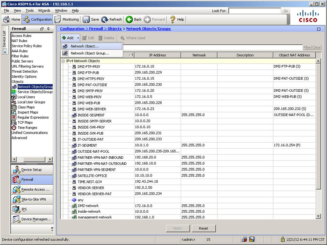
Figure 8-26. Add Network Objects/Groups Menu
From this menu, click Network Object to open the Add Network Object dialog box, shown in Figure 8-27.
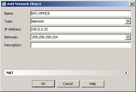
Figure 8-27. Add Network Object Dialog Box
Defining a network object is straightforward: Assign a name to the object (optional), enter an IP address and netmask, and add a description of the object (optional).
Note
If you define a network object without a name, the name assigned will be the IP address you enter when defining the object.
In Figure 8-27, the name NYC-OFFICE is assigned. The IP address of 192.0.2.32 is entered, with a netmask of 255.255.255.224. Complete the definition of the new network object by clicking OK.
Repeat these steps and define 192.0.2.64/27 as LA-OFFICE, 192.0.2.96/27 as CHI-OFFICE, and 192.0.2.128/27 as HOU-OFFICE.
After you create these individual network objects, you are returned to Configuration > Firewall > Objects > Network Objects/Groups. Click the arrow next to the Add button, and this time click Network Object Group to open the Add Network Object Group dialog box, shown in Figure 8-28.
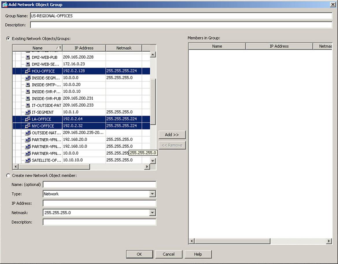
Figure 8-28. Add Network Object Group Dialog Box
In the Group Name field, assign a name for this new network object group. The group name can be up to 64 characters in length (spaces are not allowed). The name must be unique for each object group, no matter what type (that is, a network object group cannot have the same name as a service object group). In Figure 8-28, the name US-REGIONAL-OFFICES is assigned. You may optionally enter a description.
Because you have predefined the network objects that will be members of this group, click the Existing Network Objects/Groups radio button. Within that listing, select the objects representing the four regional offices, as shown in Figure 8-28 (you can select multiple objects simultaneously by using Ctrl-click or, if contiguous, Shift-click). Then click the Add >> button in the middle of the window, to move these objects into the Members in Group list. The resulting display is shown in Figure 8-29.
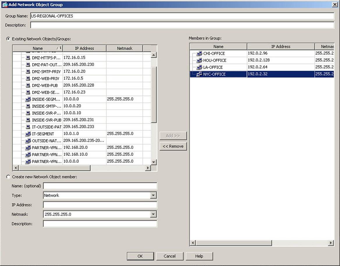
Figure 8-29. New Object Group Members Added
Note
As shown in Figure 8-29, you can optionally create new network objects as group members directly from this window, by clicking the Create New Network Object Member radio button, defining network object parameters in the designated fields, and then clicking the Add >>button.
After you verify that the Members in Group list is correct, finalize the creation of this new object group by clicking OK. The display returns to the Network Objects/Groups window, which shows all network objects at the top of the window and object groups below that. Figure 8-30 shows this display, including the object group just created.
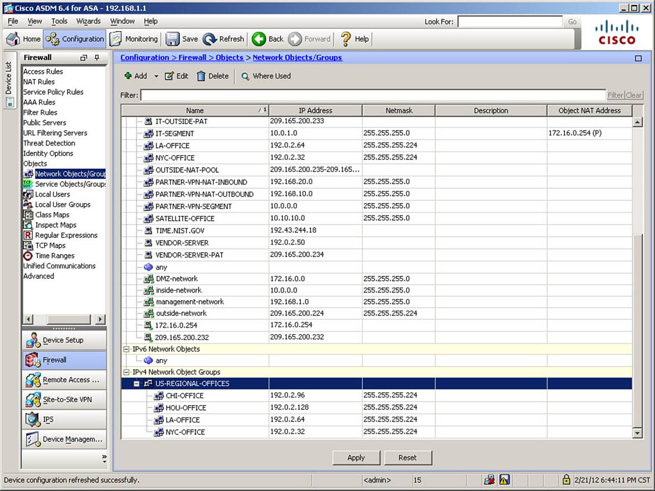
Figure 8-30. Expanded Object Group View
You can expand the view to show the membership of an object group by clicking the + sign to the left of the group name. In Figure 8-30, this has been done for the group US-REGIONAL-OFFICES.
Note that the four network objects that are members of this group remain in the list of network objects. Network objects can be reused in a number of ways in the ASA configuration, to include membership in multiple object groups, NAT rules, MPF, and so on. Adding objects to a group does not remove them from the list of network objects, but rather references the original object.
The next requirement in the configuration scenario is to allow multiple services to be reached by any host on the inside network. Previously, only HTTP access had been permitted. Because the source (the inside network) and destination (any other interface) are the same as a previously created rule, the easiest way to accomplish this new requirement is to create a service object group, containing all the desired services, and then edit the existing access rule.
You therefore need to create a service object group, which will include the TCP protocols HTTP, HTTPS, and FTP as members. To demonstrate an alternate method of doing so, navigate to Configuration > Firewall > Access Rules to return to the Access Rules window. Next, from the ASDM menu, choose View > Services. This opens the Services panel on the far right side of the ASDM window, as shown in Figure 8-31.
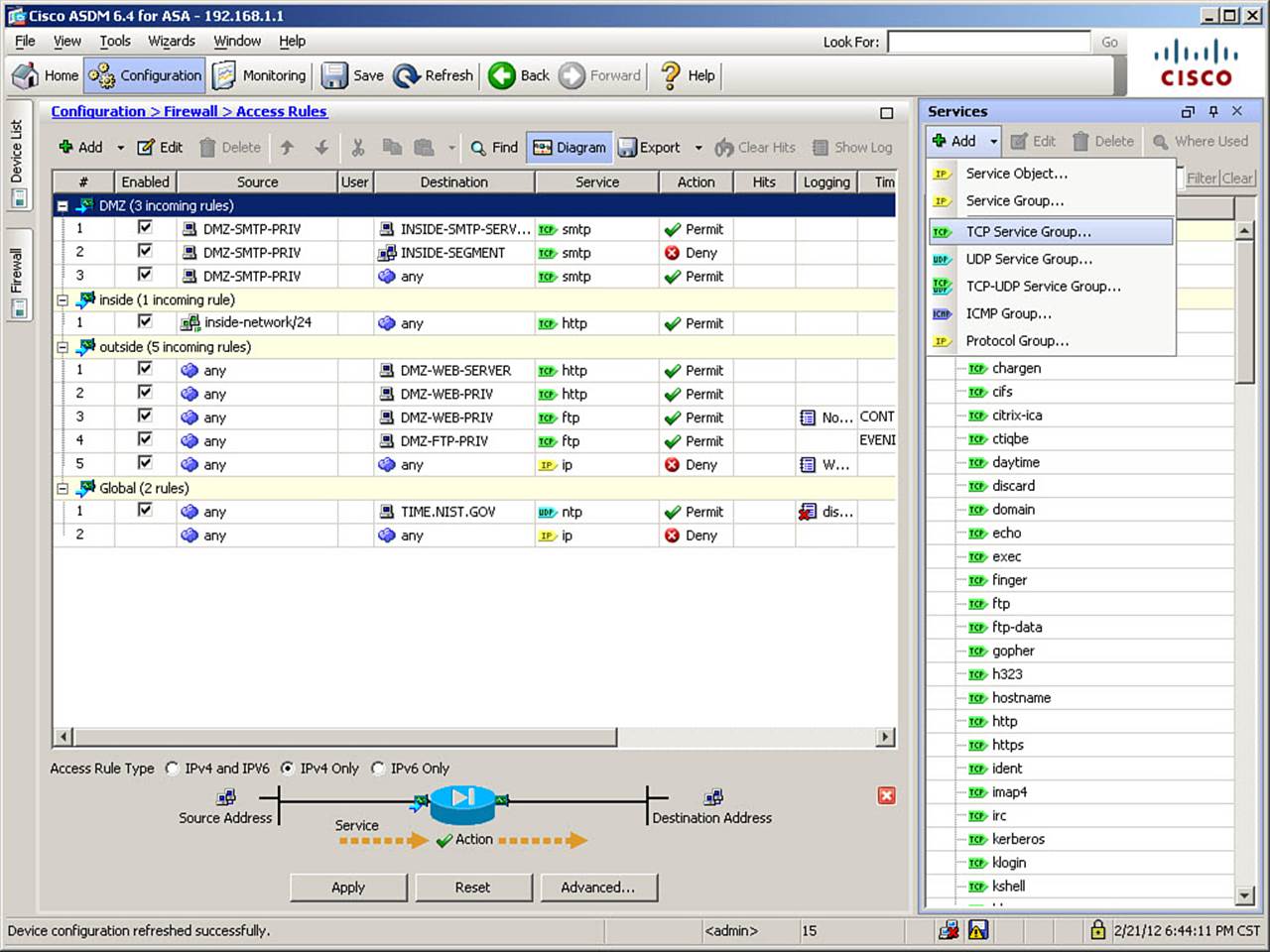
Figure 8-31. Services Panel Expanded
Note
Similar panels may be activated from the View menu for Addresses (which allows the creation of network object groups) and Time Ranges.
Within the Services panel, click Add > TCP Service Group. Doing so opens the Add TCP Service Group dialog box, which is shown in Figure 8-32.
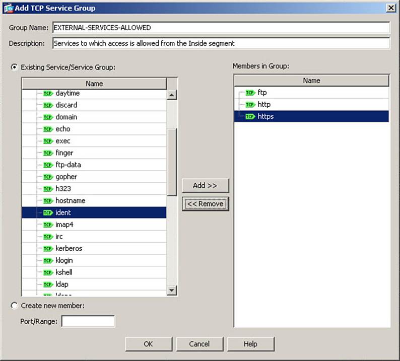
Figure 8-32. Add TCP Service Group Dialog Box
Assign a name to the Service object group in the Group Name field. You may optionally enter a description. In Figure 8-32, the name EXTERNAL-SERVICES-ALLOWED is entered, along with a brief description of the group’s purpose.
Because you chose to create a TCP Service Group, all the predefined TCP service names are listed in the Existing Service/Service Group list. This is a list of services (in alphabetical order) associated with known port numbers, and allows you to quickly build service groups without having to memorize associated port numbers. If you need to add a service that is not in the predefined list, click the Create New Member radio button and enter a port number or range in the provided field.
For our configuration scenario, using the same method described earlier, add the HTTP, HTTPS, and FTP services to the group, as shown completed in Figure 8-32. Finalize the creation of this Services object group by clicking OK. Note that the newly created group will now appear at the bottom of the Services panel.
Object group types that can be created from within the Services panel are as follows:
• Service Group: Creates an IP service object group, which groups services based on arbitrary protocols
• TCP Service Group: Creates a TCP service object group, which groups services that use only the TCP protocol
• UDP Service Group: Creates a UDP service object group, which groups services that use only the UDP protocol
• TCP-UDP Service Group: Creates a TCP and UDP service object group, which allows you to group services that use the same destination port over both the TCP and UDP protocols (for example, DNS on port 53)
• ICMP Group: Creates an ICMP-type object group, which allows you to group various ICMP service types (for example, echo-reply, unreachable, and time-exceeded in a “response” group)
• Protocol Group: Creates a Protocol object group, which allows you to group IP protocols (for example, EIGRP and OSPF in a “routing protocols” group)
Now that the required object groups have been created, you can reference them when creating or editing access rules. To change the existing access rule on the inside interface, from allowing only outbound HTTP to allowing all three protocols in the object group just created, close the Services panel and return to the Access Rules window. Then, to demonstrate the “edit in place” feature of ASDM, double-click the field for Service within the existing access rule for the inside interface. It currently shows a value of tcp/http. The field transitions to edit mode, and an ellipsis button appears to the right of the field, as shown in Figure 8-33.
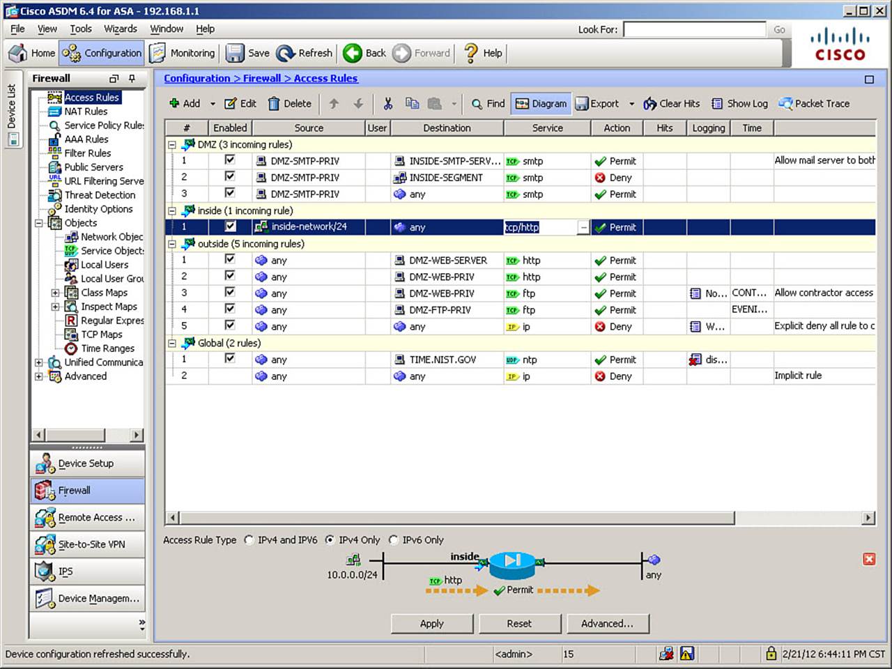
Figure 8-33. Editing an Existing Access Rule
Click the ellipsis button to open the Browse Service dialog box, as shown in Figure 8-34.
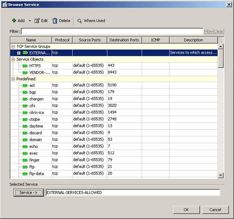
Figure 8-34. Browse Service Dialog Box
Note in Figure 8-34 that all user-defined object groups are listed at the top of the Browse Service dialog box, above the list of predefined services.
First, you need to delete the current setting of TCP/HTTP as the destination service. Simply delete the value from the Service field at the bottom of the window. Then, select the EXTERNAL-SERVICES-ALLOWED object group, and click the Service -> button to assign the object group as the selected service. This is shown in Figure 8-34. Finalize the assignment of the object group as the selected service by clicking OK. This returns the view to the Access Rules window, and the object group name is now displayed in the Service column of the inside interface access rule.
The final requirement in the configuration scenario is to permit the four U.S. regional offices to access the DMZ FTP server from midnight to 4:59 a.m. on weekdays. The current rule on the outside interface permits any source address to do so, so you will once again need to edit an existing access rule to change this requirement.
Using the same method as before, select the Source field of the existing access rule for editing by double-clicking it. Click the ellipsis button to open the Browse Source dialog box, as shown in Figure 8-35.
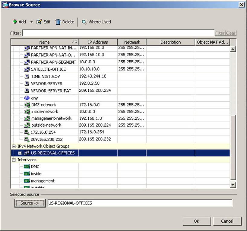
Figure 8-35. Browse Source Dialog Box
You will notice that network object groups are listed below network objects in this view. First, delete the “any” entry in the Source field, then select the object group US-REGIONAL-OFFICES, and assign it as the new source by clicking the Source -> button. Click OK to finalize the assignment and return to the Access Rules window. Figure 8-36 shows the revised contents of the ASA Access Rules.
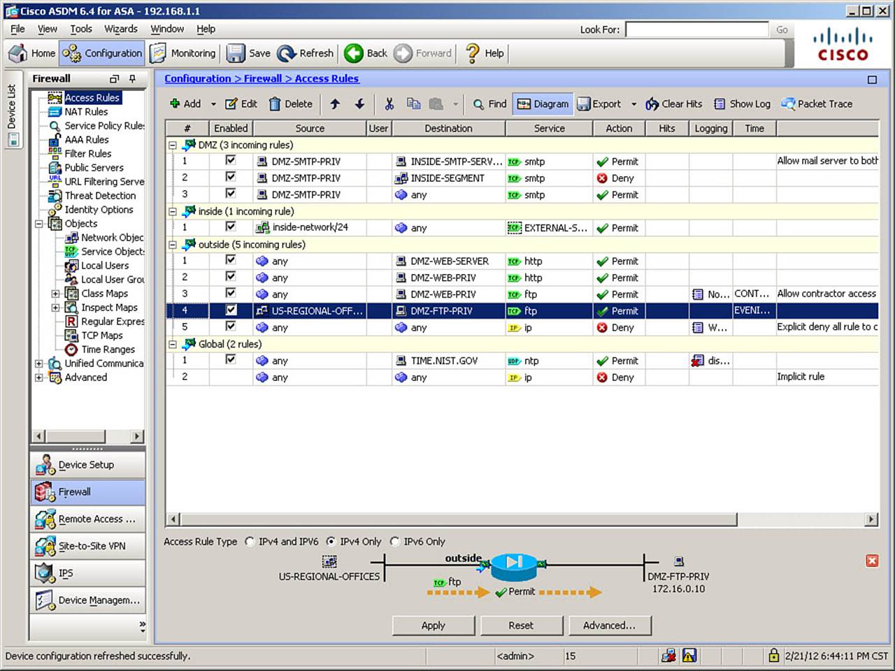
Figure 8-36. Modified Access Rules with Object Groups
Finally, click Apply to send the changes to the ASA, and then click Save to store the revised configuration as the startup-config file.
The CLI commands generated by the changes made are as follows (spacing is inserted for increased readability):
object network CHI-OFFICE
subnet 192.0.2.96 255.255.255.224
object network HOU-OFFICE
subnet 192.0.2.128 255.255.255.224
object network LA-OFFICE
subnet 192.0.2.64 255.255.255.224
object network NYC-OFFICE
subnet 192.0.2.32 255.255.255.224
!
object-group network US-REGIONAL-OFFICES
network-object object CHI-OFFICE
network-object object HOU-OFFICE
network-object object LA-OFFICE
network-object object NYC-OFFICE
!
object-group service EXTERNAL-SERVICES-ALLOWED tcp
description Services to which access is allowed from the Inside segment
port-object eq ftp
port-object eq http
port-object eq https
!
access-list INSIDE-IN line 1 extended permit tcp 10.0.0.0 255.255.255.0 any object-
group EXTERNAL-SERVICES-ALLOWED
!
no access-list INSIDE-IN line 2 extended permit tcp 10.0.0.0 255.255.255.0 any eq
http
!
no access-list OUTSIDE-IN line 5 extended permit tcp any object DMZ-FTP-PRIV eq
ftp time-range EVENING-FTP-TRANSFERS
!
access-list OUTSIDE-IN line 5 extended permit tcp object-group US-REGIONAL-OFFICES
object DMZ-FTP-PRIV eq ftp time-range EVENING-FTP-TRANSFERS
If you are configuring the ASA from the CLI, you can enter these commands directly in global configuration mode.
Note that, to replace an element in an ACE with an object group, you place the keyword object-group in front of the group name, in the ACE syntax. You may freely mix object-group-based ACE conditions with classic, single-service or single-address ACE conditions.
Verifying Object Groups
At their core, object groups are for our consumption as human administrators—they allow us to easily create or edit access rule entries and allow us to use easily understood logical names to refer to groups of addresses, ports, protocols, or ICMP types that would otherwise need to be enumerated within the ASA configuration. They do not, however, actually alter the functionality of access rules, from the ASA’s point of view.
You can verify the application of object groups within access rules by opening the Services panel (shown previously in Figure 8-31) or Addresses panel and cross-referencing them with the Access Rules table. You can also verify group membership by expanding the view of any object group within either of these panels. Figure 8-37 shows the Addresses panel (choose View > Addresses), with the US-REGIONAL-OFFICES object group membership expanded.
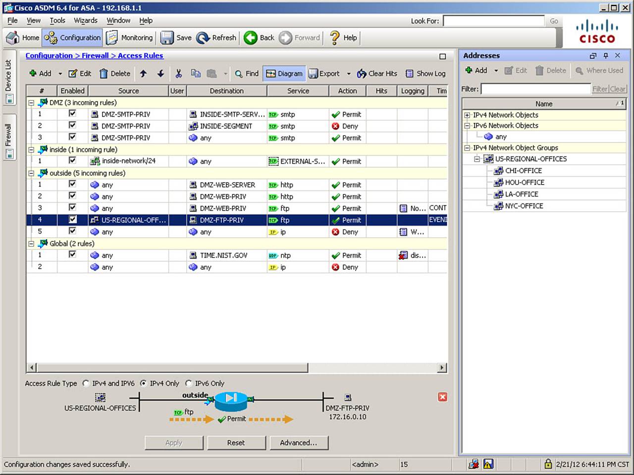
Figure 8-37. Verifying Object Groups in ASDM
Editing the membership of an object group automatically updates any access rule that references the object group. This makes the editing of underlying ACLs far easier than manually locating rules for deletion or inserting new ACEs in the correct position within a long and complex ACL.
The difference between how you might edit access rules containing object groups and how the ASA operates on them can be demonstrated using show commands. Example 8-10 shows a “logical” view of the configured access lists, which is how administrators edit ACLs. Note how short and concise this listing is.
Example 8-10. show running-config access-list Output with Object Groups
FIREWALL# show running-config access-list
access-list INSIDE-IN extended permit tcp 10.0.0.0 255.255.255.0 any object-group
EXTERNAL-SERVICES-ALLOWED
access-list DMZ-IN remark Allow mail server to both inside and Internet
access-list DMZ-IN extended permit tcp object DMZ-SMTP-PRIV object INSIDE-SMTP-SERVER
eq smtp
access-list DMZ-IN extended deny tcp object DMZ-SMTP-PRIV object INSIDE-SEGMENT eq smtp
access-list DMZ-IN extended permit tcp object DMZ-SMTP-PRIV any eq smtp
access-list OUTSIDE-IN extended permit tcp any object DMZ-WEB-SERVER eq www
access-list OUTSIDE-IN extended permit tcp any object DMZ-WEB-PRIV eq www
access-list OUTSIDE-IN remark Allow contractor access to update web server content
access-list OUTSIDE-IN extended permit tcp any object DMZ-WEB-PRIV eq ftp log
notifications time-range CONTRACTOR-TO-WEB-SERVER
access-list OUTSIDE-IN extended permit tcp object-group US-REGIONAL-OFFICES object DMZ-
FTP-PRIV eq ftp time-range EVENING-FTP -TRANSFERS
access-list OUTSIDE-IN remark Explicit deny all rule to change to interval log message
106100 from per-packet log message 106023
access-list OUTSIDE-IN extended deny ip any any log warnings
access-list GLOBAL-ACL extended permit udp any object TIME.NIST.GOV eq ntp log disable
Example 8-11 shows the same access lists, as the ASA actually operates on them, by using the show access-list command, without the running-config argument. As previously mentioned, when using this command, the ASA will expand all object groups to display individual ACEs for each combination of object group members in a rule.
Example 8-11. show access-list Output with Object Groups
FIREWALL# show access-list
access-list cached ACL log flows: total 0, denied 0 (deny-flow-max 4096)
alert-interval 300
access-list INSIDE-IN; 3 elements; name hash: 0xf1656621
access-list INSIDE-IN line 1 extended permit tcp 10.0.0.0 255.255.255.0 any object-
group EXTERNAL-SERVICES-ALLOWED (hitcnt=0) 0xe86dade4
access-list INSIDE-IN line 1 extended permit tcp 10.0.0.0 255.255.255.0 any eq ftp
(hitcnt=0) 0x5f8d3c2c
access-list INSIDE-IN line 1 extended permit tcp 10.0.0.0 255.255.255.0 any eq www
(hitcnt=0) 0x31ef50e1
access-list INSIDE-IN line 1 extended permit tcp 10.0.0.0 255.255.255.0 any eq https
(hitcnt=0) 0xc6f6c701
access-list DMZ-IN; 3 elements; name hash: 0x33999acc
access-list DMZ-IN line 1 remark Allow mail server to both inside and Internet
access-list DMZ-IN line 2 extended permit tcp object DMZ-SMTP-PRIV object INSIDE-SMTP-
SERVER eq smtp (hitcnt=0) 0xa283a3e0
access-list DMZ-IN line 2 extended permit tcp host 172.16.0.20 host 10.0.0.20
eq smtp (hitcnt=0) 0xa283a3e0
access-list DMZ-IN line 3 extended deny tcp object DMZ-SMTP-PRIV object INSIDE-
SEGMENT eq smtp (hitcnt=0) 0x89a59184
access-list DMZ-IN line 3 extended deny tcp host 172.16.0.20 10.0.0.0
255.255.255.0 eq smtp (hitcnt=0) 0x89a59184
access-list DMZ-IN line 4 extended permit tcp object DMZ-SMTP-PRIV any eq smtp
(hitcnt=0) 0x3b8b87ca
access-list DMZ-IN line 4 extended permit tcp host 172.16.0.20 any eq smtp (hitcnt=0)
0x3b8b87ca
access-list OUTSIDE-IN; 8 elements; name hash: 0x9ccc1a31
access-list OUTSIDE-IN line 1 extended permit tcp any object DMZ-WEB-SERVER eq www
(hitcnt=0) 0x40178d02
access-list OUTSIDE-IN line 1 extended permit tcp any host 172.16.0.23 eq www
(hitcnt=0) 0x40178d02
access-list OUTSIDE-IN line 2 extended permit tcp any object DMZ-WEB-PRIV eq www
(hitcnt=0) 0xccb8bc5d
access-list OUTSIDE-IN line 2 extended permit tcp any host 172.16.0.5 eq www
(hitcnt=0) 0xccb8bc5d
access-list OUTSIDE-IN line 3 remark Allow contractor access to update web server
content
access-list OUTSIDE-IN line 4 extended permit tcp any object DMZ-WEB-PRIV eq ftp log
notifications interval 300 time-range CONTRACTOR-TO-WEB-SERVER (hitcnt=0)
(inactive) 0xcef8e373
access-list OUTSIDE-IN line 4 extended permit tcp any host 172.16.0.5 eq ftp
log notifications interval 300 time-range CONTRACTOR-TO-WEB-SERVER (hitcnt=0)
(inactive) 0xcef8e373
access-list OUTSIDE-IN line 5 extended permit tcp object-group US-REGIONAL-
OFFICES object DMZ-FTP-PRIV eq ftp time-range EVENING-FTP-TRANSFERS (inactive)
0xc53e606d
access-list OUTSIDE-IN line 5 extended permit tcp 192.0.2.96255.255.255.224 host
172.16.0.10 eq ftp time-range EVENING-FTP-TRANSFERS (hitcnt=0) (inactive)
0x30426396
access-list OUTSIDE-IN line 5 extended permit tcp 192.0.2.128 255.255.255.224 host
172.16.0.10 eq ftp time-range EVENING-FTP-TRANSFERS (hitcnt=0) (inactive)
0x04fec957
access-list OUTSIDE-IN line 5 extended permit tcp 192.0.2.64 255.255.255.224 host
172.16.0.10 eq ftp time-range EVENING-FTP-TRANSFERS (hitcnt=0) (inactive)
0xbdf6d167
access-list OUTSIDE-IN line 5 extended permit tcp 192.0.2.32 255.255.255.224 host
172.16.0.10 eq ftp time-range EVENING-FTP-TRANSFERS (hitcnt=0) (inactive)
0xae58cf00
access-list OUTSIDE-IN line 6 remark Explicit deny all rule to change to interval log
message 106100 from per-packet log message 106023
access-list OUTSIDE-IN line 7 extended deny ip any any log warnings interval 300
(hitcnt=0) 0x502c4bfb
access-list GLOBAL-ACL; 1 elements; name hash: 0xf07a8f76
access-list GLOBAL-ACL line 1 extended permit udp any object TIME.NIST.GOV eq ntp log
disable (hitcnt=0) 0xebbdaf93
access-list GLOBAL-ACL line 1 extended permit udp any host 192.43.244.18 eq ntp log
disable (hitcnt=0) 0xebbdaf93
Obviously, this output is far more lengthy. Observe that, in line 1 of access list INSIDE-IN, the object group EXTERNAL-SERVICES-ALLOWED is expanded into its individual membership. All entries use the same line number, but this view is helpful, as you can see hit counts for each object group member, which is especially helpful when troubleshooting.
Configuring and Verifying Other Basic Access Controls
In addition to interface access rules, the ASA supports Unicast Reverse Path Forwarding (uRPF) and shunning of hosts or connections.
Creating per-interface access rules to protect against IP masquerade packets (spoofed source address) can be very labor-intensive. Because the ASA can refer to its own routing table to determine which networks are reachable through which interface, it can use the same method to validate source addresses of incoming packets. This is known as Unicast Reverse Path Forwarding (uRPF), and the ASA supports strict uRPF, where packets must arrive at a correct interface to be accepted.
When a packet arrives at an interface where uRPF has been enabled, the ASA performs the following checks:
1. Does the packet belong to an existing connection? If a packet belongs to a connection in the connection table, its source address is considered valid and it is passed to the inspection engines. The ASA always tracks both interfaces that a transit connection is using, and will deny packets that arrive at an unexpected interface for an existing connection.
2. Is the source address valid for the ingress interface? If a packet does not belong to an existing connection (or uses a stateless protocol, in which case every packet in the flow must be validated), the ASA extracts the source address from the packet and performs a uRPF check. The routing table is consulted to determine if the network to which the address belongs is reachable through the interface where the packet is arriving. If it is, the packet is forwarded to the inspection engines.
3. If the packet fails the uRPF check, the packet is dropped and a violation is logged, using the message ID 106021, which distinguishes this type of drop from the “generic” drop message of 106023.
By default, uRPF is disabled on all interfaces. You should consider enabling it unless you know of legitimate asymmetric flows that will transit the ASA. The application of uRPF will break asymmetric flows, and if such flows exist, properly configured interface access rules should be used instead.
Note
Because uRPF relies on the ASA routing table, it is only as trustworthy as the routing table itself. That is, if routing is not properly secured (using routing protocol authentication and filtering when using dynamic routing protocols), uRPF will be unreliable. Additionally, all packets from addresses not explicitly in the ASA routing table will match a configured default route, so although enabling uRPF on the interface used by the default route (usually the outside interface) will prevent spoofing of source addresses the ASA knows to be located through other interfaces, it will not prevent spoofing of invalid source IP addresses that are not known to the ASA.
Because the examples are for a small network, you will not enable uRPF on the outside interface; the vast majority of packets will match the default route, so it is not likely worth the processing overhead to use uRPF instead of interface access rules to prevent spoofed sources from the outside in this particular network. To enable uRPF on some or all remaining ASA interfaces, navigate to Configuration > Firewall > Advanced > Anti-Spoofing. The Anti-Spoofing window opens, as shown in Figure 8-38.
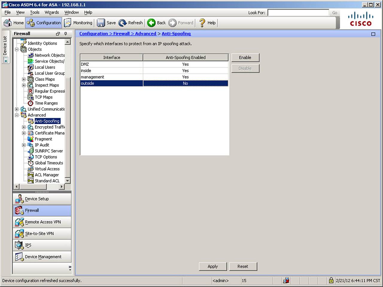
Figure 8-38. Enabling uRPF
Select the interface on which you want to enable uRPF, and click Enable. Figure 8-38 shows uRPF enabled on all but the outside interface. Then, click Apply to send the change to the ASA.
The CLI commands generated by the changes made are as follows:
ip verify reverse-path interface inside
ip verify reverse-path interface DMZ
ip verify reverse-path interface management
If you are configuring the ASA from the CLI, you can enter these commands directly in global configuration mode.
Shunning
Packet shunning is an ASA feature that allows you to quickly block all packets from a particular IP address at the ASA, regardless of ingress interface, interface access rules, or even existence of a connection in the connection state table. In short, it overrides all methods by which a packet might be permitted to traverse the ASA.
Shunning is configured in one of three ways: manually by an administrator; automatically by a Cisco Intrusion Prevention System (IPS) sensor (including the ASA AIP-SSM module, described in Chapter 15, “Integrating ASA Service Modules”), which can automatically deploy shunning rules in response to detected attacks; or automatically as a result of configuring the scanning threat-detection feature. You should generally use shunning to quickly respond to the occurrence of a security incident. Because shuns do not become part of the ASA configuration file, and are therefore not persistent across reboots, the feature allows you to isolate traffic from a particular host without modifying the permanent access policy configured on the ASA. This gives you the ability to immediately protect your network from an apparently hostile host, and then take the time to analyze the situation to determine if adding a permanent block of the host to the ASA’s access rules is appropriate.
Shunning can be configured only through the CLI, and not from within ASDM. Use the shun command and specify a source IP address to shun. Example 8-12 shows the usage of the shun command, first to block all traffic from a source host, and second to block only a single TCP connection.
Example 8-12. shun Command Usage
FIREWALL# shun 192.0.2.153
Shun 192.0.2.153 added in context: single_vf
Shun 192.0.2.153 successful
FIREWALL# shun 192.0.2.231 209.165.200.228 40000 80 6
Shun 192.0.2.231 added in context: single_vf
Shun 192.0.2.231 successful
Shunning of individual connections is usually performed by a Cisco Intrusion Prevention Sensor, rather than manually. However, full support for manual connection shunning is now supported. In some older OS versions, the options showed up in output, but you could not manually shun a connection—you could only shun a source address. Note, however, that only a single shun entry can exist for any one source host at any time. Therefore, if you shun a single connection, and the host launches an attack from a different source port, the shun would have no effect on that subsequent attack—you cannot add multiple shun entries for the same host.
Use the show shun command to display the list of all currently blocked hosts. Note that the ASA automatically applies the shun only to the interface through which the shunned address is reachable, according to its routing table. You can alternately use the show shun statistics command to observe the number of packets dropped because of host shunning. Example 8-13 shows the usage of the show shun and show shun statistics commands.
Example 8-13. show shun Command Usage
FIREWALL# show shun
shun (outside) 192.0.2.153 0.0.0.0 0 0 0
FIREWALL# show shun statistics
outside=ON, cnt=3
inside=OFF, cnt=0
DMZ=OFF, cnt=0
management=OFF, cnt=0
Shun 192.0.2.153 cnt=3, time=(0:00:49)
Use the clear shun command to disable all shunning rules currently enabled. You may also use the clear shun statistics command to clear only the packet counters.
Troubleshooting Basic Access Control
You can use a combination of CLI commands and Cisco ASDM verification and debugging tools to troubleshoot issues related to basic access control. Typically, you will be seeking to determine why a particular session cannot be established through the ASA when you believe it should be. Occasionally, you will need to determine why sessions you believe should be denied are being permitted through the ASA.
There are a number of tools available for troubleshooting basic access control issues, including ASA logs, a packet capture capability, and the Packet Tracer tool, available both from the CLI and within ASDM.
Examining Syslog Messages
The following shows an example of syslog messages created by the ASA when a connection is permitted. If you see these messages, but your connection does not get established, you should verify the routing information in your network, especially if connection slots are inactivated with a SYN timeout, when using TCP.
%ASA-7-609001: Built local-host inside:10.0.0.108
%ASA-7-609001: Built local-host outside:192.0.2.150
%ASA-6-305011: Built dynamic TCP translation from inside:10.0.0.108/49334 to
outside:209.165.200.226/46683
%ASA-6-302013: Built outbound TCP connection 237 for outside:192.0.2.150/80
(192.0.2.150/80) to inside:10.0.0.108/49334 (209.165.200.226/46683)
If the ASA denies a new connection based on interface access rules, you will see either the standard 106023 messages or, if you altered the default logging (as demonstrated earlier in this chapter), 106100 messages:
%ASA-4-106100: access-list OUTSIDE-IN denied tcp outside/192.0.2.232(49314) ->
DMZ/172.16.0.10(80) hit-cnt 1 first hit [0x2c1c6a65, 0x0]
You might also see the 106015 message, which would indicate that a noninitial packet has arrived at an ASA interface but does not match any existing connections in the connection table. This usually indicates either a reconnaissance attack attempt or legitimately delayed packets that were not received until after their transport connection had been closed.
If a packet is denied by uRPF on an interface, you will see this type of syslog message:
%ASA-1-106021: Deny UDP reverse path check from 172.27.25.42 to 172.27.25.255 on
interface inside
Finally, if a packet is denied by shunning, you will see this type of syslog message:
%ASA-4-401004: Shunned packet: 192.0.2.232 ==> 209.165.200.228 on interface outside
You can view the syslog messages in the ASA log using the CLI show logging command (if buffered logging is enabled), or you can use the Cisco ASDM Real-Time Log Viewer. To use the Real-Time Log Viewer, both system logging and ASDM logging must be enabled. You can access the Real-Time Log View by navigating to Monitoring > Logging > Real-Time Log Viewer and clicking View to open the Real-Time Log Viewer window, shown in Figure 8-39.
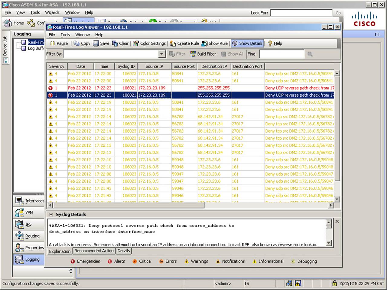
Figure 8-39. ASDM Real-Time Log Viewer
The Real-Time Log Viewer contains tabs at the bottom of the window that offer explanations, recommended actions, or detailed information on a selected message within the log. You can also filter the displayed messages, or search them, using the Filter By and Find fields at the top of the window.
You can use the Cisco ASDM rule-to-log correlation feature to observe syslog messages that are generated by packets matching a specific interface access rule. To do so, navigate to Configuration > Firewall > Access Rules and right-click a specific rule to open the Access Rule menu. From this menu, choose the Show Log option, as shown in Figure 8-40. This will cause the Real-Time Log Viewer to open, displaying only messages that match the selected access rule.
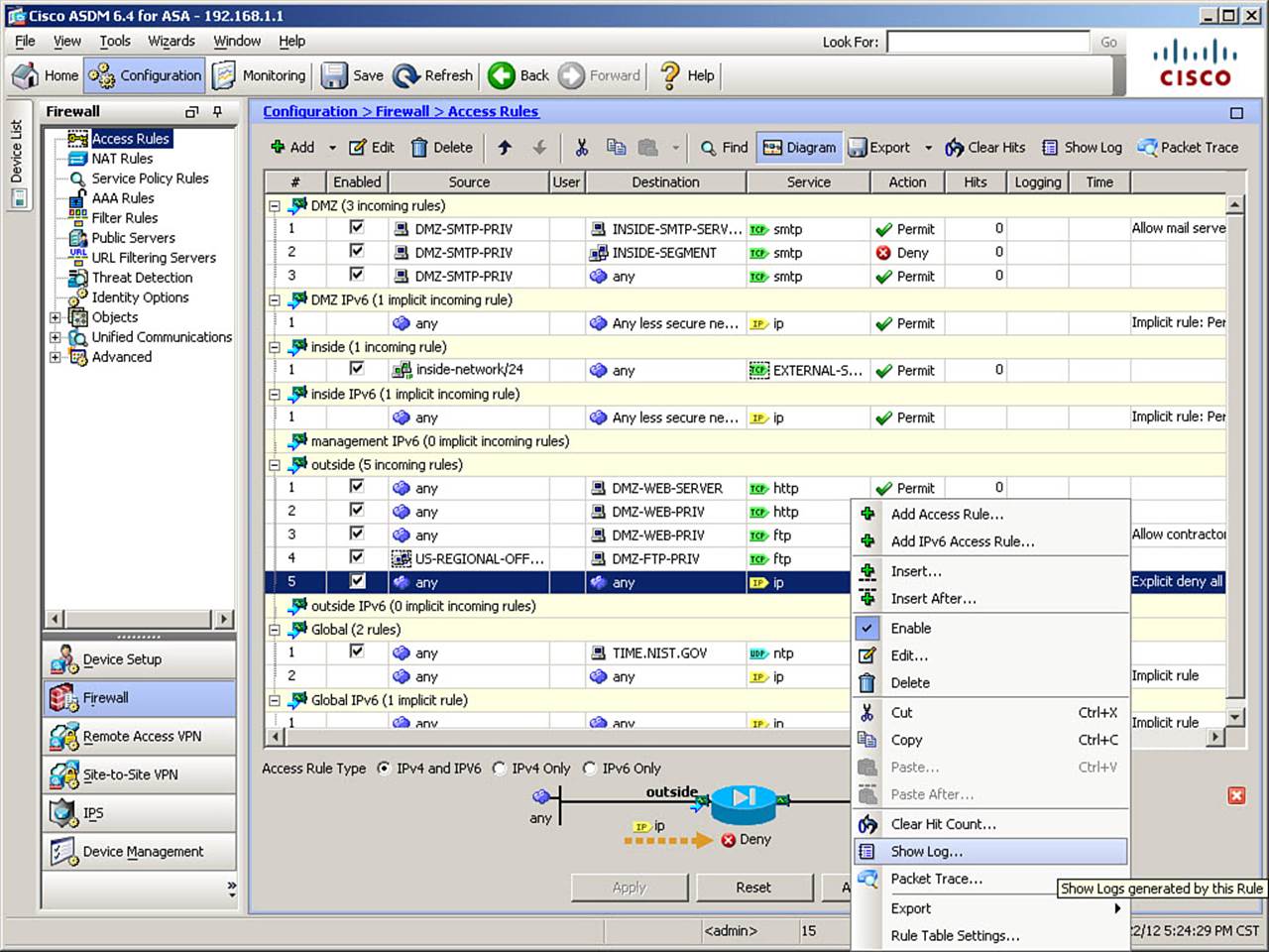
Figure 8-40. Access Rule-to-Log Correlation Feature
An additional tool offered by the Cisco ASDM Real-Time Log Viewer is the ability to create a permit access rule from a deny syslog message. Select a log message that indicates that a desired connection has been denied, and click the Create Rule button at the top of the Real-Time Log Viewer window. An interface access rule will be automatically created, which will permit this connection in the future, and you are given an opportunity to review the rule before it is applied.
Packet Capture
The packet capture utility is covered in detail in Chapter 16, “Traffic Analysis Tools”; however, it is possible to use a variation of the capture command to capture only those packets that were denied by interface access rules. You do so by adding the type asp-drop acl-drop parameter to thecapture command. Example 8-14 shows an example of creating such a packet capture and displaying the resulting captured packets.
Example 8-14. capture Command Limited to ACL Drops
FIREWALL# capture ACL-DROPS type asp-drop acl-drop
FIREWALL# show capture ACL-DROPS
13 packets captured
1: 04:21:58.081584 209.165.200.245.56838 > 192.168.100.3.161: udp 77 Drop-reason:
(acl-drop) Flow is denied by configured rule
2: 04:21:58.611189 209.165.200.245.49368 > 209.165.200.229.80: S
2739424558:2739424558 (0) win 8192 <mss 1460,nop,wscale 2,nop,nop,sackOK>
Drop-reason:
(acl-drop) Flow is denied by configured rule
...output omitted...
13: 04:22:21.878662 209.165.200.245.49369 > 209.165.200.228.443: S
2330381003:2330381003(0) win 8192 <mss 1460,nop,nop,sackOK> Drop-reason:
(acl-drop)
Flow is denied by configured rule
13 packets shown
Packet Tracer
When troubleshooting basic access control, the Packet Tracer tool, also covered in Chapter 16, allows you to quickly pinpoint possible reasons for connectivity issues through the ASA. The Packet Tracer tool is available through either the CLI or Cisco ASDM. Within ASDM, you access it from the Tools menu. When the Packet Tracer window opens, specify the connection parameters you want to simulate and test, the input interface, and the source and destination IP addresses and ports, and then click Start. Figure 8-41 shows an example of a completed Packet Tracer test.
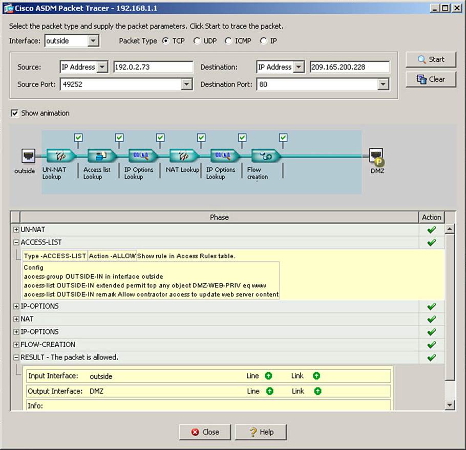
Figure 8-41. Packet Tracer Utility Results
Figure 8-41 shows a sample test using the outside interface as the ingress interface for the packet. The source address tested is 192.0.2.73, with a source port of 49252. The destination is the translated address assigned to the DMZ web server, 209.165.200.228, with a destination port of HTTP. The ACCESS-LIST section of the output is expanded to show the specific rule that permitted the packet, and the RESULT line of the output is selected for easy reference.
Note
When using packet tracer with the outside interface as a source, you must enter the translated address for an internal server to run the test. Packet tracer simulates the arrival of a packet containing the exact information you specify in all address/port fields. Therefore, you must enter information as it would appear in the packet BEFORE arriving at the ASA and being subjected to translation rules. This differs from how you configure rules, always referring to an internal host by its native address. Note, however, that although the example tests a destination IP of 209.165.200.228, the access list line that shows as a match is the one which permits access to DMZ-WEB-PRIV, which was defined as 172.16.0.5. You may also want to consider unchecking the Show Animation option to increase the speed of the test when using the GUI Packet Tracer utility.
Example 8-15 shows an example of invoking the Packet Tracer tool from the CLI. You supply the same connection information as in the ASDM tool. This example shows the same source and destination addresses as the preceding example, but the destination service is changed to port 443, which is not allowed by the interface access rules.
Example 8-15. packet-tracer Command Usage
FIREWALL# packet-tracer input outside tcp 192.0.2.73 49252 209.165.200.228 443
Phase: 1
Type: UN-NAT
Subtype: static
Result: ALLOW
Config:
object network DMZ-WEB-PRIV
nat (DMZ,outside) static DMZ-WEB-PUB dns
Additional Information:
NAT divert to egress interface DMZ
Untranslate 209.165.200.228/443 to 172.16.0.5/443
Phase: 2
Type: ACCESS-LIST
Subtype: log
Result: DROP
Config:
access-group OUTSIDE-IN in interface outside
access-list OUTSIDE-IN extended deny ip any any log warnings
Additional Information:
Result:
input-interface: outside
input-status: up
input-line-status: up
output-interface: DMZ
output-status: up
output-line-status: up
Action: drop
Drop-reason: (acl-drop) Flow is denied by configured rule
Suggested Approach to Access Control Troubleshooting
An orderly approach to access control troubleshooting follows. This is a suggested guide only, and not all steps will be appropriate in all situations. This example is based on troubleshooting a connection that is not establishing when you think it should.
Step 1. Determine if the interface on which the connection is arriving uses an inbound set of access rules (ACL). You can accomplish this by using the CLI show running-config access-group command or examining the ASDM Access Rules window. If the interface on which the connection is arriving does use an inbound set of access rules, verify that the access rule set permits this connection by using the CLI or ASDM Packet Tracer tool, by examining ASA log files for denied connections, or by using the packet capture tool to view dropped packets. Do not forget to consider the contents of the global ACL in your review. If no issues are revealed by these checks, proceed to Step 3. If the rule set is found not to permit the connection, create a permit rule to permit it.
Step 2. If the ingress interface does not use an inbound rule set, you should determine if the egress interface to which the connection is routed has a lower security level. If it does, the connection should be automatically permitted, and you can proceed to Step 3. If the connection is routed to an egress interface with a higher security level, you will need to create an interface access rule set (ACL) to permit such a connection. Depending on your network addressing, you might also need to create a static translation for the destination host. For example, packets inbound to the outside interface, and trying to reach a server on the DMZ with an RFC 1918 private IP address natively assigned.
Step 3. Determine whether the egress interface to which the connection is routed uses an outbound access rule set (an outbound ACL). You can verify this by using the CLI show running-config access-group command or by examining the ASDM Access Rules window. If it does, verify that the access rule set permits this connection using the same methods described in Step 1. If no issues are revealed by these checks, proceed to Step 4. If the rule set is found not to permit the connection, create a permit rule to permit it.
Step 4. Verify whether uRPF is enabled on the ingress interface by using the show running-config ip verify reverse-path command. If it is not, proceed to Step 6.
Step 5. If uRPF is enabled on the ingress interface, verify that it does not block the connection. Use the show logging command or the ASDM Real-Time Log Viewer to find possible denied packets. Use the show route command to examine the routing table and verify whether the route for the source address points to the correct interface.
Step 6. Verify that the connection is not shunned by the ASA. Use the show shun command to display currently shunned hosts and connections. If the host is in the shunning list, consider removing the host from the shunning list using the no shun host ip command, if this is acceptable and does not increase risk.
Exam Preparation Tasks
As mentioned in the section, “How to Use This Book,” in the Introduction, you have a couple of choices for exam preparation: the exercises here, Chapter 17, “Final Preparation,” and the exam simulation questions on the CD-ROM.
Review All Key Topics
Review the most important topics in this chapter, noted with the Key Topic icon in the outer margin of the page. Table 8-4 lists a reference of these key topics and the page numbers on which each is found.
Table 8-4. Key Topics for Chapter 8
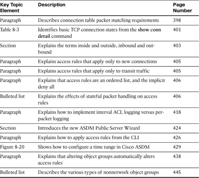
Command Reference to Check Your Memory
This section includes the most important configuration and EXEC commands covered in this chapter. It might not be necessary to memorize the complete syntax of every command, but you should be able to remember the basic keywords that are needed.
To test your memory of the commands, cover the right side of Tables 8-5 through 8-14 with a piece of paper, read the description on the left side, and then see how much of the command you can remember.
Table 8-5. Commands Related to State Tables
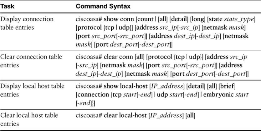
Table 8-6. Optional show conn and clear conn Parameters
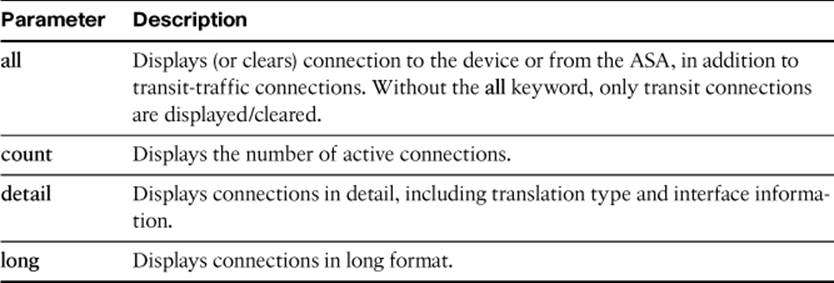
Table 8-7. Optional show local-host and clear local-host Parameters
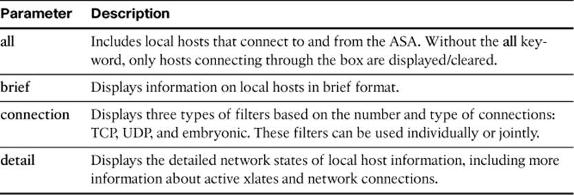
Table 8-8. Commands Related to Access Lists
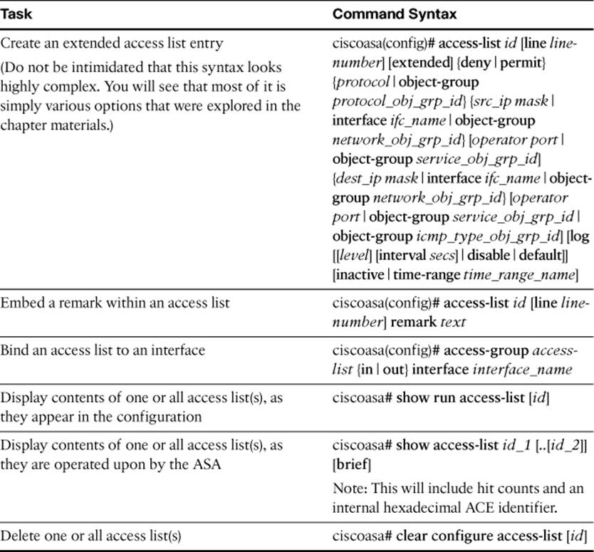
Table 8-9. access-list extended Parameters
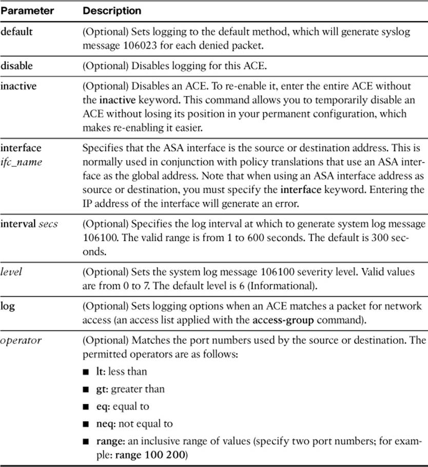
Table 8-10. Commands Related to Time Range
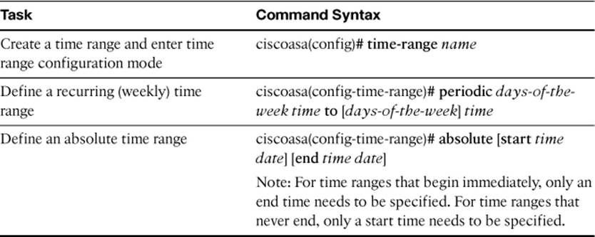
Table 8-11. Time-Range periodic Parameters
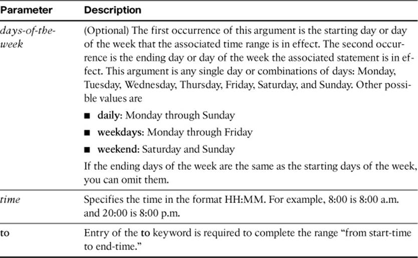
Table 8-12. Commands Related to Object Groups
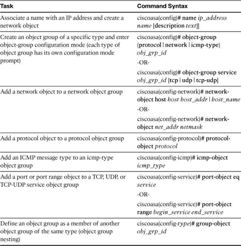
Table 8-13. Object Group Parameters
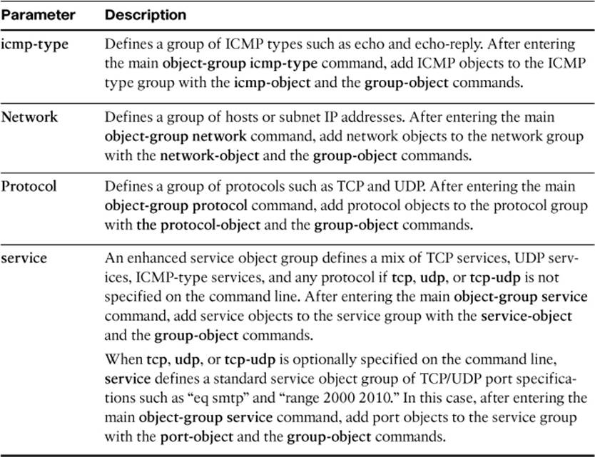
Table 8-14. Commands Related to Other Access Controls
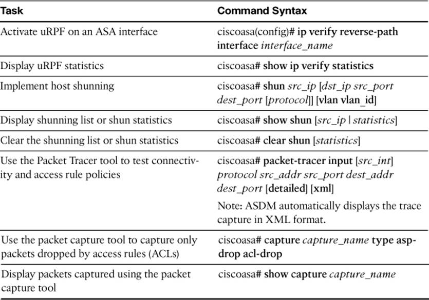
The FIREWALL exam focuses on practical, hands-on skills that are used by a networking professional. Therefore, you should be able to identify the commands needed to configure and test an ASA feature.
All materials on the site are licensed Creative Commons Attribution-Sharealike 3.0 Unported CC BY-SA 3.0 & GNU Free Documentation License (GFDL)
If you are the copyright holder of any material contained on our site and intend to remove it, please contact our site administrator for approval.
© 2016-2026 All site design rights belong to S.Y.A.