Implementing Cisco IOS Network Security (IINS) Foundation Learning Guide, Second Edition (2013)
Part III: Threat Control and Containment
Chapter 11. Intrusion Prevention Systems
This chapter describes the functions and operations of intrusion detection systems (IDS) and intrusion prevention systems (IPS). This chapter will introduce you to
• The fundamentals of intrusion prevention, comparing IDS and IPS
• The building blocks of IPS, introducing the underlying technologies and deployment options
• The use of signatures in intrusion prevention, highlighting the benefits and drawbacks
• The need for IPS alarm monitoring, evaluating the options for event managers
• Analyzing the design considerations in deploying IPS
IPS Fundamentals
Intrusion detection system (IDS) and intrusion prevention system (IPS) solutions form an integral part of a robust network defense solution. Maintaining secure network services is a key requirement of a profitable IP-based business. To show how these systems work, this chapter uses Cisco products and technologies as examples.
Introducing IDS and IPS
The evolution of threats and business models requires a new approach to intrusion prevention:
• Targeted, mutating, stealth threats are increasingly difficult to detect. Intrusion prevention needs to be distributed and embedded end to end along the “path of intrusion.” Shared threat and security intelligence is a key feature.
• Attackers have insidious motivations and exploit high-impact targets, often for financial benefit or economic and political reasons. The impact on business continuity is immense. More than ever, intrusion prevention needs to be accurate, providing a timely and precise response only to threats relevant to the infrastructure, application, and business environments of the organization.
• Attackers are taking advantage of new ways of communication. Borderless networks provide a launching pad for high-impact intrusion from mobile users to consumer devices (smartphones, PDAs, tablet devices, entertainment devices, book readers, and so on), exploiting data wherever it may be stored (user’s personal device, enterprise data centers, cloud service providers, and so on). The “army of intrusion sensors” requires flexible deployment options, from appliances to hardware modules on existing network elements to software-based and virtualized form factors.
Traditionally, an IDS and an IPS work together to provide a network security solution. An IDS captures packets in real time, processes them, and can respond to threats, but it works on copies of data traffic to detect suspicious activity by using signatures. This is called promiscuous mode. In the process of detecting malicious traffic, an IDS allows some malicious traffic to pass before the IDS can respond to protect the network. An IDS analyzes a copy of the monitored traffic rather than the actual forwarded packet. The advantage of operating on a copy of the traffic is that the IDS does not affect the packet flow of the forwarded traffic. The disadvantage of operating on a copy of the traffic is that the IDS cannot stop malicious traffic from single-packet attacks from reaching the target system before the IDS can apply a response to stop the attack. An IDS often requires assistance from other networking devices, such as routers and firewalls, to respond to an attack.
An IPS works inline in the data stream to provide protection from malicious attacks in real time. This is called inline mode. Unlike an IDS, an IPS does not allow packets to enter the trusted side of the network. An IPS monitors traffic at Layer 3 and Layer 4 to ensure that the traffic’s headers, states, and so on are those specified in the protocol suite. However, the IPS sensor analyzes the payload of the packets at Layer 2 to Layer 7 for more sophisticated embedded attacks that might include malicious data. This deeper analysis lets the IPS identify, stop, and block attacks that would normally pass through a traditional firewall device. When a packet comes in through an interface on an IPS, that packet is not sent to the outbound or trusted interface until the packet has been determined to be clean. An IPS builds upon previous IDS technology; Cisco IPS platforms use a blend of detection technologies, including profile-based intrusion detection, signature-based intrusion detection, and protocol analysis intrusion detection.
The key to differentiating an IDS from an IPS is that an IPS responds immediately and does not allow any malicious traffic to pass, whereas an IDS allows malicious traffic to pass before it can respond. IDSs typically are IPSs that are configured to work on a copy of the traffic (promiscuous mode) instead of working on traffic going through it (inline mode). Because IDS devices are usually IPS devices configured differently, in this chapter we often use the term IPS, which, in our generic conversation on the topic, will also encompass IDS, unless indicated otherwise.
IDS:

• Analyzes copies of the traffic stream
• Does not slow network traffic
• Allows some malicious traffic into the network
IPS:
• Works inline in real time to monitor Layer 2 through Layer 7 traffic and content
• Needs to be able to handle network traffic
• Prevents malicious traffic from entering the network
IDS and IPS technologies share several characteristics:
• IDS and IPS technologies are deployed as sensors. An IDS or an IPS sensor can be any of the following devices:
• A router configured with Cisco IOS IPS Software
• An appliance specifically designed to provide dedicated IDS or IPS services
• A network module installed in a Cisco adaptive security appliance, switch, or router
• IDS and IPS technologies typically monitor for malicious activities in two spots:
• Network: To detect attacks against the network, including attacks against hosts and devices, using network IDS and network IPS.
• Hosts: To detect attacks launched from or against target machines, using host IPS (HIPS). Host-based attacks are detected by reading security event logs, checking for changes to critical system files, and checking system registries for malicious entries.
• IDS and IPS technologies use signatures to detect patterns of misuse in network traffic. A signature is a set of rules that an IDS or IPS uses to detect typical intrusive activity. Signatures are usually chosen from a broad cross section of intrusion detection signatures, and can detect severe breaches of security, common network attacks, and information gathering.
• IDS and IPS technologies look for the following general patterns of misuse:
• Atomic pattern: In an atomic pattern, an attempt is made to access a specific port on a specific host, and malicious content is contained in a single packet. An IDS is particularly vulnerable to an atomic attack because until the IDS finds the attack, malicious single packets are being allowed into the network. An IPS prevents these packets from entering at all.
• Composite pattern: A composite pattern, also referred to as compound, is a sequence of operations distributed across multiple hosts over an arbitrary period of time.
Inline Sensors
Sensors, even inline, might not be completely successful at dropping packets of an attack. An attack might be underway, if only partially, before an inline sensor even starts to drop packets matching a composite pattern signature. The drop action is much more effective for atomic signatures because the sensor makes a single-packet match.
Figure 11-1 shows a sensor deployed in IDS mode and a sensor deployed in IPS mode.
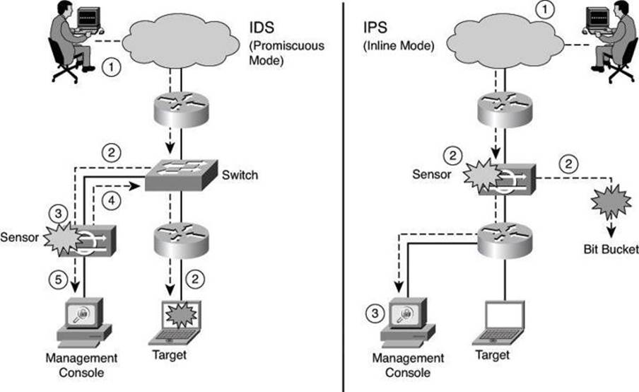
Figure 11-1. IDS and IPS Operational Differences
The following are the steps that occur when an attack is launched in an environment monitored by an IDS:
Step 1. An attack is launched on a network that has a sensor deployed in IDS mode.
Step 2. The switch sends copies of all packets to the IDS sensor (configured in promiscuous mode, which is explained later in this section) to analyze the packets. At the same time, the target machine experiences the malicious attack.
Step 3. The IDS sensor, using a signature, matches the malicious traffic to the signature.
Step 4. The IDS sensor sends to the switch a command to deny access to the malicious traffic.
Step 5. The IDS sends an alarm to a management console for logging and other management purposes.
The following are the steps that occur when an attack is launched in an environment monitored by an IPS:
Step 1. An attack is launched on a network that has a sensor deployed in IPS mode (configured in inline mode, which is explained later in this section).
Step 2. The IPS sensor analyzes the packets as soon as they come into the IPS sensor interface. The IPS sensor, using signatures, matches the malicious traffic to the signature and the attack is stopped immediately. Traffic in violation of policy can be dropped by an IPS sensor.
Step 3. The IPS sensor can send an alarm to a management console for logging and other management purposes.
Promiscuous Versus Inline Mode
A sensor can be deployed either in promiscuous mode or inline mode. In promiscuous mode, the sensor receives a copy of the data for analysis, while the original traffic still makes its way to its ultimate destination. By contrast, a sensor working inline analyzes the traffic live and therefore can actively block the packets before they reach their destination.
It is worth mentioning that Cisco appliances such as the Cisco ASA AIP-SSM (discussed later in this chapter), although advertised as IPS devices, can work either in promiscuous mode or in inline mode.
Management Console
The term management console, used in this chapter and seen in Figure 11-1, refers to a separate workstation equipped with software to configure, monitor, and report on events. The section “Monitoring Cisco IOS IPS Alarms and Event Managers” introduces some of the Cisco IPS management solutions.
Table 11-1 lists some of the advantages and limitations of deploying platform sensors in promiscuous mode; in other words, as an IDS.
Table 11-1. Advantages and Limitations of Deploying a Sensor in Promiscuous Mode: IDS
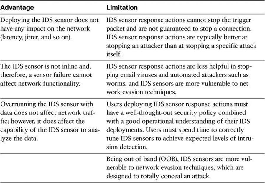
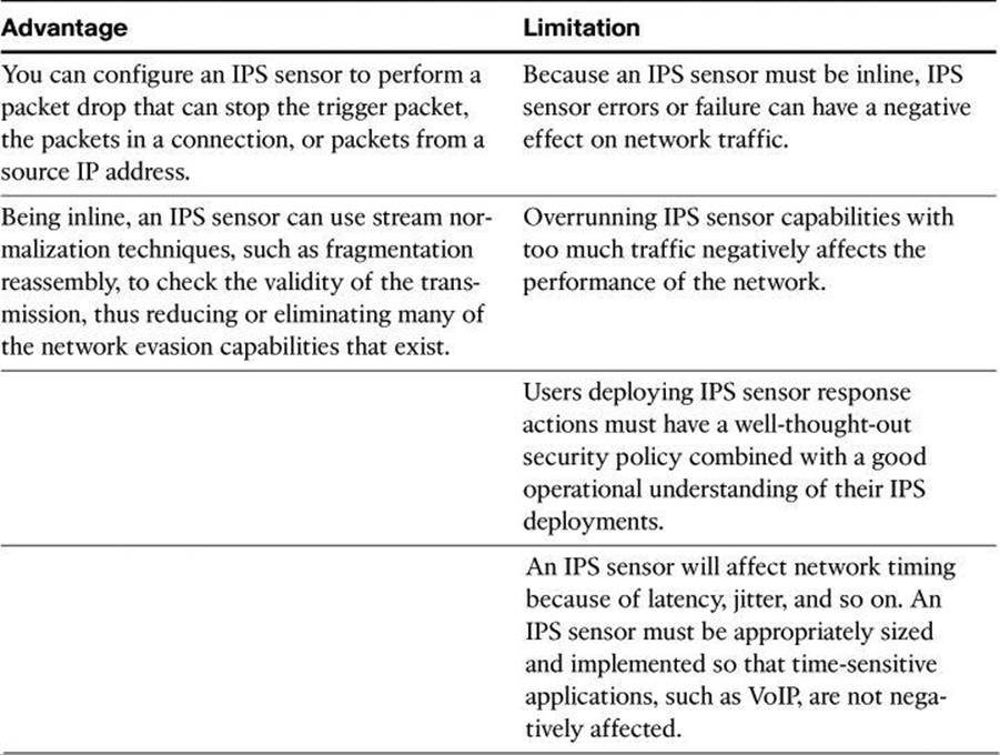
Table 11-2 lists some of the advantages and limitations of deploying a platform sensor in inline mode; in other words, as an IPS.
Table 11-2. Advantages and Limitations of Deploying a Sensor in Inline Mode: IPS
So, IDS or IPS? Why Not Both?
When designing a distributed IPS architecture, both IDS and IPS deployment modes can be used to improve the accuracy, intelligence, response, and performance of the architecture. When combined, IDSs in promiscuous mode and IPSs in inline mode complement each other to accomplish this objective. Figure 11-2 illustrates an example, described next.
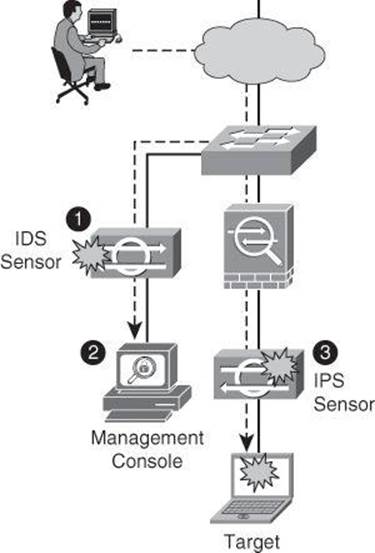
Figure 11-2. Using Both IDS and IPS Devices
The IDS sensor in front of the firewall is deployed in promiscuous mode to monitor traffic in the untrusted network. It is likely that this IDS sensor will have more visibility over a wide variety of events and malicious traffic that have the potential to become security incidents. The internal network is protected initially by the firewall, and the role of the IDS sensor is to gather security intelligence in order to define a baseline of current and relevant threats. This information is then correlated and fed into the detection capabilities of the internal IPS sensor.
The IPS sensor behind the firewall can therefore focus on monitoring the internal network and detect incidents originated inside. It can also implement a more restrictive policy for external traffic, while remaining accurate, using the information gathered and baselined by the IDS sensor.
Alarm Types
As shown in the previous figures, IDS and IPS sensors produce alarms. The capability of IDS and IPS sensors to accurately detect an attack or a policy violation and generate an alarm is critical to the functionality of the sensors. Attacks can generate the following types of alarms:
• False positive: A false positive is an alarm triggered by normal traffic or a benign action. Consider this scenario: A signature exists that generates alarms if the enable password of any network devices is entered incorrectly. A network administrator attempts to log in to a Cisco router but enters the wrong password. The IDS cannot distinguish between a rogue user and the network administrator, and it generates an alarm.
• False negative: A false negative occurs when a signature is not fired when offending traffic is detected. Offending traffic could range from a corporate user pinging too aggressively a target on the Internet, to attacks against corporate web servers. A false negative should be considered a software bug if the IDS and IPS have a signature that has been designed to detect the offending traffic but failed to do so. In this situation, the failure to trigger on the offending traffic should be reported to the vendor of the IPS product.
• True positive: A true positive occurs when an IDS and IPS signature is correctly fired and an alarm is generated when offending traffic is detected. For example, consider a Unicode attack. Cisco IPS sensors have signatures that detect Unicode attacks against Microsoft Internet Information Services (IIS) web servers. If a Unicode attack is launched against Microsoft IIS web servers, the sensors detect the attack and generate an alarm.
• True negative: A true negative occurs when a signature is not fired when non-offending traffic is captured and analyzed. In other words, the sensor does not fire an alarm when it captures and analyzes “normal” network traffic.
Figure 11-3 provides a summary of the alarm types. To understand the terminology, think in terms of the question, “Was the alarm triggered?” A positive means that the alarm was triggered and a negative means that the alarm was not triggered. Thus the expression false alarm, which is the same as false positive (positive because the alarm was triggered, but false because the intrusion did not happen or the intrusion was not detected by the sensor).
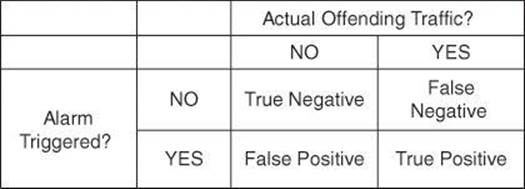
Figure 11-3. Making Sense of Alarm Types Terminology
Note
Positive or negative refers to whether the alarm was triggered. Positive designates an alarm has been triggered, and negative designates an alarm has not been triggered. True or false is more complex; this answers the question, “Was the result to trigger (or not trigger) the alarm the right decision?” If the action taken by the sensor was right, then the result is true, and if the sensor took the wrong decision, the result is false. As an example, if malicious traffic travels through your network and the IPS sensor fails to detect it, it is a false negative. The negativerefers to the alarm not triggering. The false means not triggering was the wrong decision for the IPS sensor to take.
Intrusion Prevention Technologies
Multiple detection technologies are typically used to provide an effective intrusion detection architecture. Table 11-3 summarizes the advantages and limitations of the various types of IDS and IPS sensors available. These will be discussed in greater detail in this section.
Table 11-3. Types of IDS and IPS Sensors
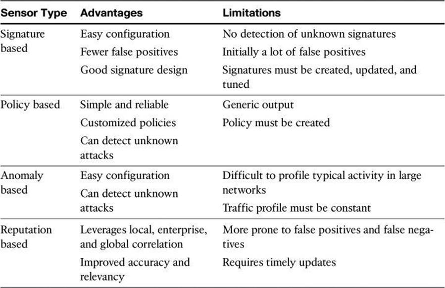
Signature-Based IDS/IPS
A signature-based approach is usually the starting point of an effective intrusion detection architecture. A signature is a set of rules that an IDS and an IPS use to detect typical intrusive activity, such as denial of service (DoS) attacks. You can easily install signatures using IDS and IPS management software such as Cisco IPS Device Manager (IDM) and Cisco IPS Express Manager (IME). Sensors allow you to modify existing signatures and define new ones.
A signature-based IDS or IPS sensor looks for specific, predefined patterns (signatures) in network traffic. It compares the network traffic to a database of known attacks, and triggers an alarm or prevents communication if a match is found. The signature can be based on a single packet or a sequence of packets. New attacks that do not match a signature do not result in detection. For this reason, the signature database needs to be constantly updated.
As sensors scan network packets, they use signatures to detect known attacks and respond with predefined actions. A malicious packet flow has a specific type of activity and signature, and an IDS or IPS sensor examines the data flow using many different signatures. When an IDS or IPS sensor matches a signature with a data flow, the sensor takes action, such as logging the event or sending an alarm to IDS or IPS management software, such as Cisco Configuration Professional (CCP).
Signature-based intrusion detection can produce false positives because certain normal network activity can be misinterpreted as malicious activity. For example, some network applications or operating systems may send out numerous Internet Control Message Protocol (ICMP) messages, which a signature-based detection system might interpret as an attempt by an attacker to map out a network segment. You can minimize false positives by tuning your sensors. You can tune built-in signatures (tuned signatures) by adjusting the many signature parameters.
Note
Protocol analysis–based intrusion detection relies on signature-based intrusion detection, where the signature performs a check to ensure that the data unit header, flags, payload, and so on respect the protocol.
Signature-based pattern matching is an approach that is rigid but simple to employ. In most cases, the pattern is matched against only if the suspect packet is associated with a particular service or, more precisely, destined to and from a particular port. This matching technique helps to lessen the amount of inspection done on every packet. However, it makes it more difficult for systems to deal with protocols that do not reside on well-defined ports, such as Trojan horses and their associated traffic, which can move at will.
At the initial stage of incorporating signature-based IDS or IPS, before the signatures are tuned, there can be many false positives (traffic generating an alert even though it is no threat to the network). After the system is tuned and adjusted to the specific network parameters, there will be fewer false positives than with the policy-based approach.
Policy-Based IDS/IPS
In policy-based systems, the IDS or IPS sensor is configured based on the network security policy. You must create the policies used in a policy-based IDS or IPS. Any traffic detected outside the policy will generate an alarm or will be dropped. Creating a security policy requires detailed knowledge of the network traffic and is a time-consuming task.
Policy-based signatures use an algorithm to determine whether an alarm should be fired. Often, policy-based signature algorithms are statistical evaluations of the traffic flow. For example, in a policy-based signature used to detect a port sweep, the algorithm issues an alarm when the threshold number of unique ports is scanned on a particular machine. Policy-based signature algorithms can be designed to analyze only specific types of packets (for example, SYN packets, where the SYN bit is turned on during the handshaking process at the beginning of the session).
The policy itself might require tuning. For example, you might have to adjust the threshold level of certain types of traffic so that the policy conforms to the utilization patterns on the network that it is monitoring. Policies can be used to look for very complex relationships.
Anomaly-Based IDS/IPS
Anomaly-based (or profile-based) signatures typically look for network traffic that deviates from what is seen “normally.” The biggest issue with this methodology is that you first must define what normal is. If during the learning phase your network is the victim of an attack and you fail to identify it, the anomaly-based IPS will interpret that malicious traffic as normal, and no alarm will be triggered the next time this same attack takes place. Some systems have hard-coded definitions of normal traffic patterns and, in this case, could be considered heuristic-based systems.
Normal behavior is typically defined based on traffic patterns, traffic and protocol mix, traffic volumes, and other criteria. This is called statistical baselining. A second approach focuses on traffic that deviates from protocol standards. This is called protocol anomaly baselining.
The technique used by anomaly-based IDS/IPS systems is also referred as network behavior analysis or heuristics analysis.
Reputation-Based IPS
A more recent approach to intrusion detection is the reputation-based IPS. This technique uses reputation analysis for various traffic descriptors, such as IP addresses, URLs, Domain Name System (DNS) domains, and others. This typically translates into reputation filters, sometimes known as white lists or black lists, that round up a signature-based system by filtering known malicious sources, destinations, or application components.
A reputation-based approach typically requires communication between the sensor and the source of the reputation information. Sources can be local to the device, which builds reputation based on the history of incidents known to the local device. However, the true power of reputation-based systems lies in the correlation of reputation information with enterprise knowledge and even global knowledge, usually provided by early warning systems, honeypots, and managed security intelligence services. Cisco Security Intelligence Operations, introduced later in this chapter, is a reputation-based IPS.
Honeypots
Honeypots can also be considered to be a form of IDS. Honeypot systems use a dummy server to attract attacks. The purpose of the honeypot approach is to distract attacks away from real network devices. By staging different types of vulnerabilities in the honeypot server, you can analyze incoming types of attacks and malicious traffic patterns. You can use this analysis to tune your sensor signatures to detect new types of malicious network traffic.
Honeypot systems are used in production environments, typically by large organizations that are considered interesting targets for hackers, such as financial enterprises, governmental agencies, and so on. Also, antivirus and other security vendors tend to use them for research.
Many security experts preach the use of honeypots as an early warning system to be deployed with your IDS/IPS system, not in lieu of. Honeyd is an example of popular open source honeypot software. Although honeypots are often found as dedicated servers, it is possible to set up virtual honeypots using VMware or Windows Virtual PC. Keep in mind that should the honeypot be successfully hacked and used as a launching platform for an attack on a third party, the honeypot’s owner could incur downstream liability.
IPS Attack Responses
Detection is only part of the role of an IPS. You should define and plan the reaction capabilities of sensors by defining the response that is triggered upon detection, no matter what detection techniques (or combination of techniques) you use.
When an IPS sensor detects malicious activity, it can choose from any or all of the following actions:
• Deny Attacker Inline: This action terminates the current packet and future packets from this attacker address for a specified period of time. The sensor maintains a list of the attackers currently being denied by the system. You can remove entries from the list or wait for the timer to expire. The timer is a sliding timer for each entry. Therefore, if attacker A is currently being denied but issues another attack, the timer for attacker A is reset, and attacker A remains on the denied attacker list until the timer expires. If the denied attacker list is at capacity and cannot add a new entry, the packet is still denied.
• Deny Connection Inline: This action terminates the current packet and future packets on this TCP flow. The packet for this flow was dropped. This is also referred to as deny flow.
• Deny Packet Inline: This action terminates the packet. The packets are dropped.
• Log Attacker Packets: This action starts IP logging on packets that contain the attacker address and sends an alert. This action causes an alert to be written to the event store, which is local to the Cisco IOS router, even if the produce-alert action is not selected. Produce alert is discussed later in a bullet.
• Log Pair Packets: This action starts IP logging on packets that contain the attacker and victim address pair. This action causes an alert to be written to the event store, even if the produce-alert action is not selected.
• Log Victim Packets: This action starts IP logging on packets that contain the victim address and sends an alert. This action causes an alert to be written to the event store, even if the produce-alert action is not selected.
• Produce Alert: This action writes the event to the event store as an alert.
• Produce Verbose Alert: This action includes an encoded dump of the offending packet in the alert. This action causes an alert to be written to the event store, even if the produce-alert action is not selected.
• Request Block Connection: This action sends a request to a blocking device to block this connection.
• Request Block Host: This action sends a request to a blocking device to block this attacker host.
• Request SNMP Trap: This action sends a request to the notification application component of the sensor to perform Simple Network Management Protocol (SNMP) notification. This action causes an alert to be written to the event store, even if the produce-alert action is not selected.
• Reset TCP Connection: This action sends TCP resets to hijack and terminate the TCP flow.
Caution
Responses to deny inline actions (packet, connection, or attacker) are not available on sensors in IDS mode.
Note
Packets that are dropped (denied) based on false alarms can result in network disruption if the dropped packets are required for mission-critical applications downstream of the IPS sensor. Therefore, do not be overly aggressive when assigning the deny-action to signature.
Also, “deny” discards the packet without sending a reset. Cisco recommends using “deny and reset” with alarm.
Also note that IP logging and verbose alert traces use a common capture file writing code called libpcap. This is the same format used by the famous packet-capture tool Wireshark (formerly Ethereal); by Snort, a famous freeware IDS; by NMAP, a well-known fingerprinting tool; and by Kismet, a famous wireless sniffing tool.
You can use the reset TCP connection action in conjunction with deny-packet and deny-flow actions. However, deny-packet and deny-connection actions do not automatically cause reset TCP connection actions to occur.
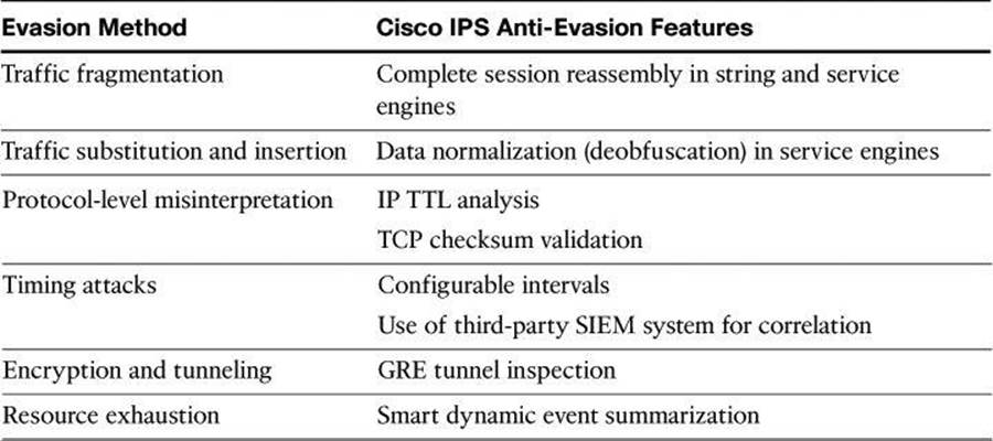
IPS Anti-Evasion Techniques
Attackers will do their best to get around your intrusion prevention architecture. Multiple IPS evasion techniques allow them to deploy exploits using a stealth approach, one that often renders IPS sensors unable to detect and prevent intrusion. These techniques include the following:
• Traffic fragmentation: Any evasion attempt where the attacker splits malicious traffic, hoping to avoid detection or filtering by confusing the network IPS sensor reassembly methods, bypassing the network IPS sensor if it does not perform any reassembly at all, or reordering split data if the network IPS sensor does not correctly order it in the reassembly process.
• Traffic substitution: The attacker attempts to evade detection by substituting payload data with other data in a different format but with the same meaning. If the IPS sensor does not recognize the true meaning of data, and only looks for data in a particular format, it may miss such malicious payloads. Examples include the use of Unicode strings, exploiting case sensitivity, substitution of spaces with tabs, and others.
• Protocol-level misinterpretation: The attacker attempts to evade detection by causing the network IPS sensor to misinterpret the end-to-end meaning of network protocols and see traffic differently from what will actually be seen and processed by the target. Consequently, the sensor will either ignore traffic that should not be ignored or vice versa.
• Timing attacks: The attacker attempts to evade detection of correlating signatures by performing their actions more slowly, not exceeding the thresholds inside the time windows that these signatures use to correlate different packets together.
• Encryption and tunneling: The attacker attempts to evade detection by encrypting packets. Sensors monitor the network and capture the packets as they traverse the network. Network-based sensors rely on the data that is being transmitted in plaintext. When packets are encrypted, the sensor captures the data but is unable to decrypt it and cannot perform meaningful analysis. This type of evasive technique assumes that the attacker has already established a secure session with the target network or host.
• Resource exhaustion: In this less subtle method of evading detection, the attacker relies on extreme resource consumption. It does not matter if such a denial is against the device or the personnel who are managing the device. Specialized tools can be used to create a tremendous number of alarms that consume the resources of the IPS device and prevent attacks from being logged.
The following anti-evasion features are available on Cisco IPS sensors:
• Complete session reassembly that supports the string and service engines that must examine a reliable byte stream between two network endpoints
• Data normalization (deobfuscation) inside service engines, where all signatures convert network traffic data into a normalized, canonical form before comparing it to the signature-matching rules
• IP Time to Live (TTL) analysis and TCP checksum validation to guard against end-to-end protocol-level traffic interpretation
• Configurable intervals for correlating signatures, or the use of an external correlation that does not require real-time resources
• Inspection of traffic inside Generic Routing Encapsulation (GRE) tunnels to prevent evasion through tunneling
• Smart and dynamic summarization of events to guard against too many alarms for high event rates
Table 11-4 summarizes the evasion methods and the corresponding Cisco IPS anti-evasion features that just described.
Table 11-4. Anti-Evasion Techniques Used by Cisco IPS
Note
Security Information and Event Management (SIEM) solutions include SIM (security information management) and SEM (security event management). A SIEM product provides real-time analysis of security alerts generated by network devices such as firewalls, IPS sensors, routers, and so forth. The network devices send their syslog, SNMP, or other format security logs to the SIEM for analysis, correlation, and reporting. SIEM solutions can be in the form of software installed on your server or appliance or event management services. Cisco’s own SIEM solution used to be the Cisco Security Monitoring, Analysis, and Response System (MARS), which is now end-of-life status. Some of the Cisco third-party partners for SIEM solutions, at the time of writing, are Splunk, ArcSoft, LogLogic, and netForensics.
Risk-Based Intrusion Prevention
Intrusion management is all about risk. Threat vectors evolve so rapidly that it becomes impossible to possess all knowledge of all threats and all threat mutations, especially when new mutations occur within hours and even minutes of the seed malware.
A common technique that is used to improve the accuracy and context awareness of the intrusion prevention architecture is illustrated in Figure 11-4. This technique aims to build a risk rating into the detection capabilities, the goal of which is to detect and respond to relevant incidents only. In turn, this should reduce noise and allow IPS administrators to focus on mitigation and not on navigating the vast amounts of information.
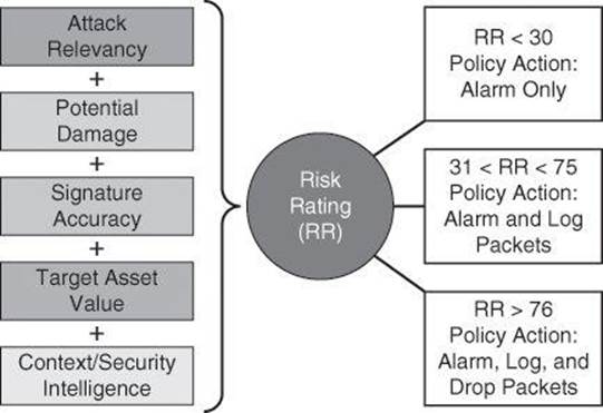
Figure 11-4. Building a Risk Rating into the Detection Capabilities
For example, an IPS sensor should detect patterns of global virus outbreaks. Using risk ratings, however, it would trigger a high-severity alert if the virus exploits the operating systems that are used in the specific network being protected, but perhaps a medium severity alert if the operating system is not in use in the organization. The response would be different for unpatched or more vulnerable servers running the relevant operating system, as opposed to fully patched servers with endpoint protection. Within these subsets, the response would be different for unpatched servers have a high asset value versus unpatched servers that store public or nonvaluable information and have a lower asset value.
Using these considerations, risk ratings typically include several components:
• Potential damage that could be caused by the activity described by the signature: Attacks that are potentially more devastating should result in higher risk ratings, and vice versa.
• Asset value of the target of the attack: Attacks against higher-valued assets should result in higher risk ratings, and vice versa.
• Accuracy of the triggering signature: Inaccurate signatures lower confidence in correct sensor decisions. Therefore, the triggering of an inaccurate signature should result in lower risk ratings, and vice versa. Additionally, sensors running in inline mode are often more accurate than sensors running in promiscuous mode, due to their traffic normalization functions. Signatures triggering in inline mode should have a correspondingly higher risk rating.
• Relevancy of the attack to the target: Attacks that cannot cause damage against their target (for example, a Windows-specific attack targeting a Linux host) should be deprioritized and assigned a lower risk rating value, because they cause no or little damage.
• Other security countermeasures (controls) in the environment: Often, these may have some additional clues that can increase the situational awareness of the sensor, and allow it to react to the current context of network events and threats. External sources of information such as honeypots and early warning systems also fit into this category. This security intelligence may also influence risk rating by raising the risk rating for events that are caused by known threats that may be experiencing global or at least significant outbreaks outside of the protected network.
Threat Rating
Cisco IPS provides a threat rating (TR) when it detects an event. The TR is the risk rating (RR) minus values associated with protective responses, called TR adjustments. TR adjustments are actions such as denying an attacker or denying the connection. So, TR = RR – TR adjustments. For example, if a risk is rated at 80 and the protection measure (such as blocking the attacker) is rated at 45, the TR is 35.
Further discussion on threat ratings is beyond the scope of this book; however, you will find plenty of information on this topic in CCNP Security IPS 642-627 Official Cert Guide (Cisco Press, 2011).
IPv6-Aware IPS
IPv6 awareness is another important consideration for IPS architectures. Sensors should be IPv6 aware; they should showcase detection techniques that consider the various threats that are found both in IPv6-only environments and in dual-stack environments where IPv4 and IPv6 coexist. As an example, IPS signatures can detect Teredo tunnels and other IPv4-to-IPv6 transition techniques, often used to exploit networks implementing dual stacks.
Alarms
Alarms fire when specific parameters are met. You must balance the number of incorrect alarms that you can tolerate with the capability of the signature to detect actual intrusions. If you have too few alarms, you might be letting in more suspect packets, but network traffic will flow more quickly. If IPSs use untuned signatures, they produce many false positive alarms, which could result in masking important alarms because they would get lost among the massive number of alarms received. You should consider the following factors when implementing alarms that a signature uses:
• The level assigned to the signature determines the alarm severity level.
• A Cisco IPS signature is assigned one of four severity levels:
• Informational: Activity that triggers the signature is not considered an immediate threat, but the information provided is useful information.
• Low: Abnormal network activity is detected that could be perceived as malicious, but an immediate threat is not likely.
• Medium: Abnormal network activity is detected that could be perceived as malicious, and an immediate threat is likely.
• High: Attacks used to gain access or cause a DoS attack are detected, and an immediate threat is extremely likely.
• You can manually adjust the severity level that an alarm produces.
• To minimize false positives, study your existing network traffic patterns and then tune your signatures to recognize intrusion patterns that are atypical (out of character) for your network traffic patterns. Do not base your signature tuning on traffic patterns that are based only on industry examples. Use industry examples as a starting point, determine what your own network traffic patterns are, and then use the results in your signature alarm tuning efforts.
• As an additional source of information, consider implementing NetFlow on network access devices such as routers and firewalls. NetFlow will collect IP traffic statistics and samples, which you can later export as NetFlow records to a NetFlow collector, such as SolarWinds or one of many others. These NetFlow statistics would assist you in characterizing the type of traffic going through your network.
IPS Alarms: Event Monitoring and Management
Event monitoring and management can be divided into the following two needs:
• Real-time event monitoring and management
• Analysis based on archived information (reporting)
These functions can be handled by a single server, or they can be placed on separate servers to scale the deployment. The number of sensors that should forward alarms to a single IPS management console is a function of the aggregate number of alarms per second generated by those sensors.
There is an important difference between reporting and monitoring. Note that archives are often a significant source of data when producing reports.
• Reporting: Analysis based on archived information
• Event monitoring: Real-time monitoring
Archiving is an important aspect for proper forensics and compliance. Ensure that your archives are properly safeguarded from potential tampering and accidental loss. Your organization should have an archiving policy, often dictated by governance of the longevity of the archive (how far back you must keep your archives). Your policies also should stipulate whether archives can be kept on site or, as usually recommended, off site.
Experience with customer networks has shown that the number of sensors reporting to a single IPS management console should be limited to 25 or fewer. These customers use a mixture of default signature profiles and tuned signatures. The number of alarms generated by each sensor is determined by how sensitively the sensor is tuned; the more sensitive the tuning, the fewer the alarms that are generated and the larger the number of sensors that can report to a single IPS management console.
Note
With the evolution of technology, the limit of 25 sensors reporting to a single IPS management console is constantly being pushed. Check with your vendor for the latest information.
Multiple protocols are available for alarm generation. Common protocols are SNMP, syslog, and Security Device Event Exchange (SDEE), the latter of which is more customized for security monitoring. SDEE is a standard developed to communicate an event generated by security devices.
When implementing multiple IPS management consoles, implement either separate monitoring domains or a hierarchical monitoring structure.
It is essential to tune out false positives to maximize the scalability of the network IPS deployment. Sensors that are expected to generate a large number of alarms, such as those sitting outside the corporate firewall, should log in to a separate IPS management console, because the number of false alarms raised dramatically increases the noise-to-signal ratio and makes it difficult to identify otherwise valid events.
Recall the following:
• False positives happen when the IDS/IPS mistakes legitimate traffic for an attack.
• False negatives happen when the IDS/IPS sensor misses an attack.
Global Correlation
Figure 11-5 illustrates a distributed approach to gathering and analyzing security intelligence and threat information. By combining local, enterprise, and global intelligence, and correlating the information at all levels, you can reduce noise and focus on relevant incidents only.
• Device intelligence is gathered on a per-device basis, and when viewed locally it will be useful for pinpointing the problem to the place in the network where the sensor is located. For instance, a port-scanning reconnaissance attack on the demilitarized zone (DMZ) could be an indication of a full-blown incident, but it could also be a minor event.
• Enterprise intelligence is gathered by all sensors of the organization and typically is centralized in a SIEM system. It provides additional information to categorize events, based on the scale and scope of the event. For instance, a port-scanning attack on the DMZ network acquires more relevance when it is followed within minutes by a firewall policy violation and a password-guessing incident on a mission-critical server.
• Global intelligence is usually gathered by early warning systems, honeypots, and managed threat services outside the organization. They give incidents a global scope. For instance, if the attack pattern detected by the enterprise SIEM is known to come from the same IP sources at a global scale, this information should trigger a more timely response. The port scanning suddenly becomes a critical incident when local, enterprise, and global information is correlated.
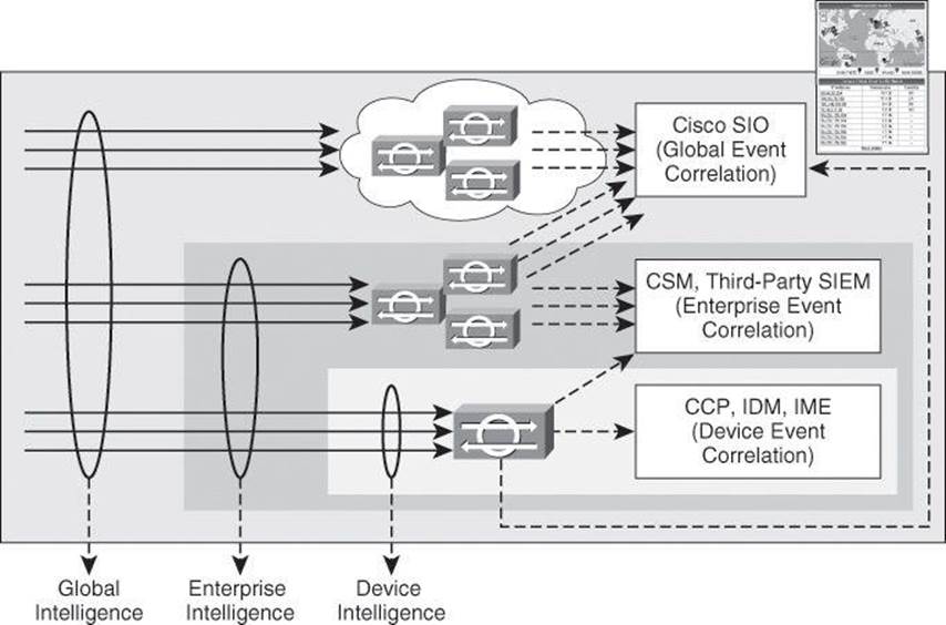
Figure 11-5. Device, Enterprise, and Global Correlation
In Figure 11-5, you will also notice the event management options using Cisco IPS architectures at local, enterprise, and global levels:
• Device event correlation: Device-level correlation is typically accomplished with products such as Cisco Configuration Professional, IPS Device Manager, or IPS Manager Express.
• Enterprise event correlation: Enterprise correlation can be gathered using Cisco Security Manager or third-party, ecosystem partner SIEM systems for more specialized event management and forensics capabilities, thus providing enterprise wide intelligence. Ecosystem partner products include ArcSight, netForensics, Splunk, and others. Refer to Cisco.com for more information; specifically, look for Cisco Security Information Event Management Deployment Guide.
• Global event correlation: Global security intelligence correlation is the responsibility of the Cisco Security Intelligence Operations (SIO) cloud-based service that connects global threat information, reputation-based services, and sophisticated analysis to Cisco network security devices to provide stronger protection with faster response times.
Why Did Cisco Pay $830M for IronPort?
Why did Cisco pay $830M to acquire IronPort in 2007? IronPort was selling great email and web security appliances, but these devices would not have justified the high price tag. Cisco bought IronPort for its crown jewel, SenderBase, since renamed Cisco IronPort SensorBase. SensorBase enables your security network devices, such as firewalls, sensors, and so forth, to not only build a risk profile on IP addresses, therefore allowing risk profiles to be dynamically created on HTTP sites and Simple Mail Transfer Protocol (SMTP) email sources, but also keep a list of IP addresses known for generating malicious activities. The information is collected and analyzed globally by Cisco SIO, which is then responsible for disseminating that information to all devices subscribing to SensorBase. You can check out Cisco SenderBase for yourself at http://www.senderbase.org. Under Reputation Lookup, plug in your domain name or www.ciscopress.com. The score is neutral and you want some excitement? Type ihaveabadreputation.com. This domain belongs to IronPort and is artificially maintained with a score of Poor to be used as a target by organizations that need to test the efficacy of their Web-Based Reputation Score filtering systems. By the way, at that website you will also find the EICAR test file, used to monitor the efficacy of virus protection.
Would you like to check the score of real domains that have been known to host malware? Visit http://www.malwaredomainlist.com for a list of malware domains. Pick an offending IP address from the list, go back to www.senderbase.org, and check the reputation of that offending domain and its history. Fascinating, isn’t it?
More information can be found on the power of SensorBase and Cisco Global Correlation, considered the best protection against zero-day attacks, at www.cisco.com/go/sio.
IPS Deployment
Different networks require different design and deployment options. Even within the same administrative domain, different network blocks will benefit from different IPS technologies, deployment options, and form factors. You should plan the IPS architecture carefully, using a “places in the network” approach and considering the different levels of risk for the different assets you are trying to protect.
Figure 11-7 illustrates two examples:
• A remote-access SSL VPN architecture, where the potential exists that users will connect to the SSL VPN gateway router using an infected device (PC, laptop, tablet, etc.). The focus of the signature database policy is on application layer inspection, and the objective is to mitigate threats coming from unmanaged and potentially exploited endpoints.
• A private WAN scenario, where a combination of Cisco IOS IPS and integrated hardware modules on ISR G2 routers provides a smaller footprint and cost-effective architecture. The focus on the signature database policy is on DoS, combined with a reputation-based approach on some branches.
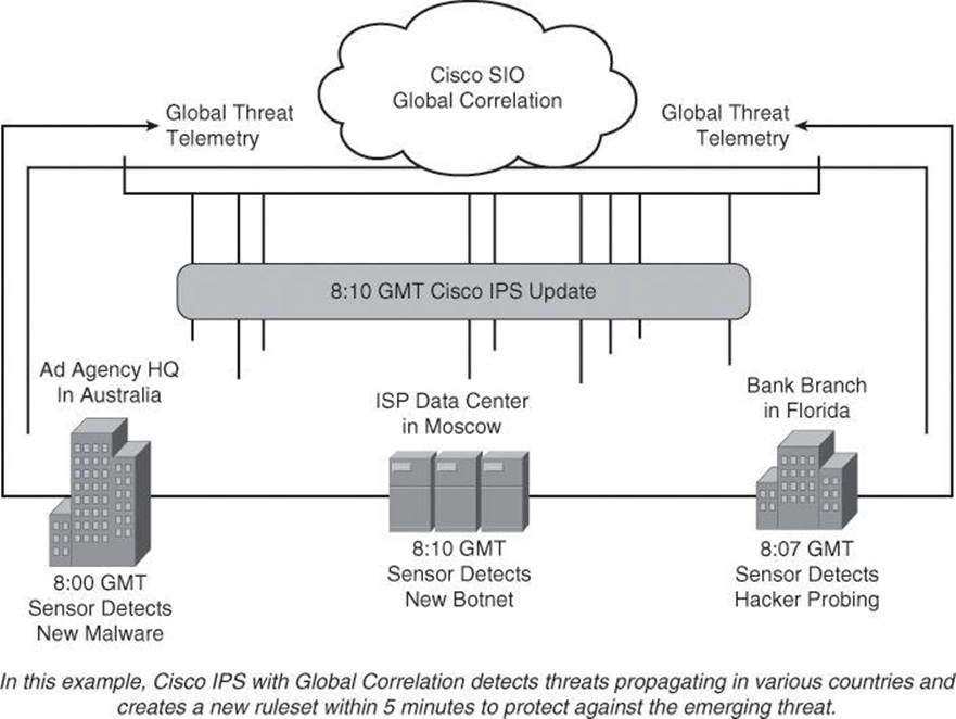
Figure 11-6. Global Correlation and Cisco SIO at Work, Preventing Zero-Day Attack
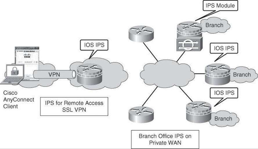
Figure 11-7. Examples of IPS Deployments
Many other places in the network can leverage the available options to deploy an effective IPS architecture.
Cisco IPS Offerings
When deploying an IPS architecture using Cisco technologies, various form factors are available to deploy intrusion prevention sensors using a distributed security intelligence approach, as shown in Figure 11-8.

Figure 11-8. IPS Platforms from Cisco
The following is a brief description of the available options and footprints:
• Cisco ASA Advanced Inspection and Prevention Security Services Module (ASA AIP-SSM): The Cisco ASA AIP-SSM uses advanced inspection and prevention technology to provide high-performance security services, such as intrusion prevention services and advanced content security services. The Cisco ASA AIP-SSM products include a Cisco ASA AIP-SSM-10 module with 1 GB of memory, a Cisco ASA AIP-SSM-20 module with 2 GB of memory, and a Cisco ASA AIP-SSM-40 module with 4 GB of memory.
• Cisco IOS IPS: Cisco IOS IPS is an inline, deep-packet inspection feature, available in Cisco Integrated Services Routers Generation 2 (ISR G2), which effectively mitigates a wide range of network attacks. A component of the Cisco IOS Integrated Threat Control framework and complemented by the Cisco IOS Flexible Packet Matching feature, Cisco IOS IPS provides your network with the intelligence to accurately identify, classify, and stop or block malicious traffic in real time.
• Cisco IPS 4200 Series Sensors: Cisco IPS 4200 Series Sensors offer significant protection to your network by helping to detect, classify, and stop threats, including worms, spyware and adware, network viruses, and application abuse. Using Cisco IPS Sensor Software Version 7.x, the Cisco IPS solution combines inline intrusion prevention services with innovative technologies that improve accuracy. As a result, more threats can be stopped without the risk of dropping legitimate network traffic. Cisco IPS Sensor Software Version 7.x includes virtualization, enhanced detection capabilities, and improved scalability, resiliency, and performance features.
• Cisco Catalyst 6500 Series Intrusion Detection System Services Module 2 (IDSM-2): The Catalyst 6500 Series IDSM-2 is part of the Cisco IPS solution. It works in combination with the other components to efficiently protect your data infrastructure. With the increased complexity of security threats, achieving efficient network intrusion security solutions is critical to maintaining a high level of protection. Vigilant protection ensures business continuity and minimizes the effect of costly intrusions.
• Cisco IPS Advanced Integration Module (IPS AIM): Cisco offers various IPS solutions using Cisco ISR G2 platforms. Cisco IPS Sensor Software running on the Cisco IPS AIM provides advanced, enterprise-class IPS functions and meets the ever-increasing security needs of branch offices. The Cisco IPS AIM can scale in performance to match branch office WAN bandwidth requirements today and in the future. At the same time, the integration of IPS onto a Cisco ISR keeps the solution cost low and effective for businesses of all sizes.
Note
Cisco IOS IPS and the Cisco IPS AIM cannot be used together. Cisco IOS IPS must be disabled when the IPS AIM is installed. Cisco IOS IPS is an IPS application that provides inspection capabilities for traffic flowing through the router. Although it is included in the Cisco IOS Advanced Security feature set, it uses the router CPU and shared memory pool to perform the inspection. Cisco IOS IPS also runs a subset of IPS signatures. The Cisco IPS AIM runs with a dedicated CPU and memory, offloading all processing of IPS signatures from the router CPU. It can load a full signature set and provide enhanced IPS features not available on Cisco IOS IPS.
New Cisco IPS Technologies and Sensors
Cisco introduced two additional IPS technologies in 2012:
• Cisco IPS 4300 Series Sensors, capable of 1-Gbps throughput.
• Cisco ASA 5500-X Series firewalls with IPS technology, including zero-day attack protection with anomaly detection, all built into the OS. These new firewalls are based on the SecureX technology and run Cisco ASA 8.6(1) code and Cisco IPS 7.1 code.
For more information on these new technologies and on all current Cisco IPS technologies, visit http://www.cisco.com/go/ips and http://www.cisco.com/go/asa.
IPS Best Practices
The following are the recommended practices for designing and deploying IPS architecture:
• Use a combination of detection technologies.
• Take advantage of multiple form factors to deploy a distributed and cost-effective IPS architecture.
• Use a “places in the network” approach, which, for Cisco, refers to the building blocks of a corporate network, such as a data center, a campus, and a branch office.
• Enable anti-evasion techniques.
• Take advantage of local, enterprise, and global correlation.
• Use a risk-based approach to improve accuracy and simplify management.
• When deploying a large number of sensors, automatically update signature packages instead of manually upgrading every sensor.
• Place the signature packages on a dedicated FTP server within the management network.
• Tune the IPS architecture constantly.
Note
A Great Debate: Fail-Close or Fail-Open?
This is another topic of discussion you could add to the list of IPS best practices. Fail-close or fail-open is a philosophical debate your organization needs to engage in: “If the IPS sensor stops working, do we let the traffic go through or do we stop the traffic?” The two opposing philosophies are represented in Figure 11-9, where the network administrator needs to decide whether the traffic will be allowed to flow into the DMZ if the Cisco ASA AIP SSM fails.
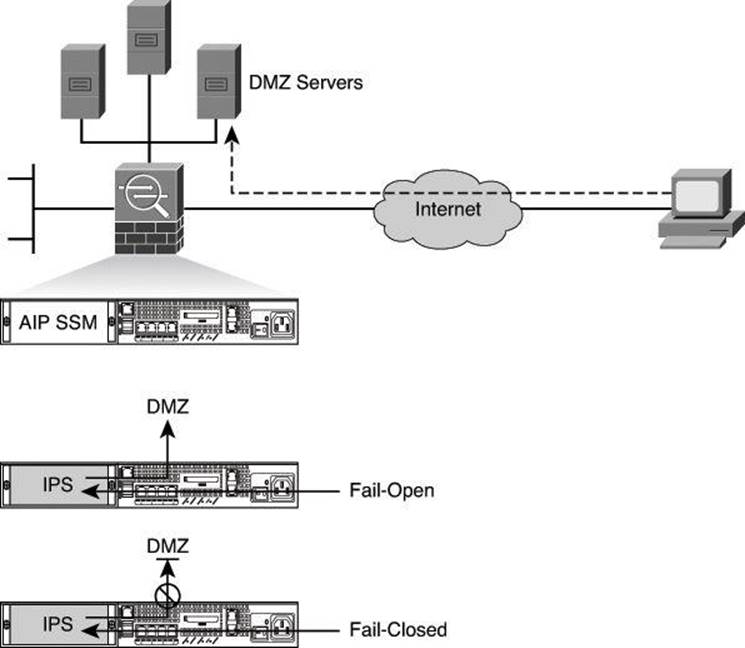
Figure 11-9. Fail-Open or Fail-Close Approach
It seems that the balance is tilting in favor of the fail-open approach with security experts, especially when dealing with for-profit organizations, but each organization has to define and enforce its own policy.
The default with Cisco IOS IPS is fail-open. You can verify this with the command show ip ips configuration, which should display “IPS fail closed is disabled.” The output of this command is shown later in Example 11-2.
Note
Readers interested in learning more about generic topics regarding IDS/IPS should consider visiting http://www.searchsecurity.com, more precisely, “Security Topics” and “Tutorials.”
Recommended practices are based on a series of key factors in current IPS architectures, required to manage evolving threats and business requirements:
• Intelligent, distributed detection
• Vulnerability- and exploit-specific signatures
• Protocol anomaly detection
• Knowledge base anomaly detection
• Reputation filters
• Accurate, precise response to relevant attacks
• Risk management–based policy
• Global correlation adding reputation
• On-box correlation
• “Trustworthiness” linkages with the endpoint
• Flexible deployment options
• Passive and/or inline with flexible response (IDS/IPS)
• Sensor virtualization
• Physical and logical (VLAN) interface support
• Software and hardware bypass
Cisco IPS Architecture
Cisco IPS architectures provide an effective approach to threat control and containment by implementing IPS technologies that address the key factors mentioned in the previous section. Figure 11-10 illustrates the various IPS functions that are applied to traffic as it is processed by a Cisco IPS sensor, starting with the virtual sensors. The traffic can then be analyzed by reputation filters, anti-evasion techniques, modular signature engines with automatic signature and engine updates, local and global device correlation, and risk ratings. Depending on the findings, alarm management and/or logging and forensics capabilities will be activated.
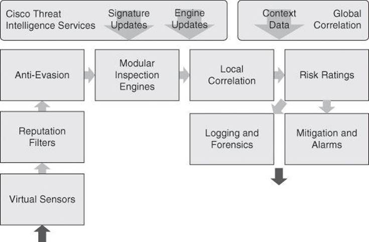
Figure 11-10. Cisco IPS Architecture
Note
Not all IPS form factors support all IPS capabilities that are shown in Figure 11-10. Please refer to the proper documentation for each IPS sensor product for specific platform details. As an example, virtual sensors are used with Cisco IPS 4x00 sensor and can be thought of as a collection of data that is defined by a set of configuration policies. A discussion on virtual sensors is beyond the scope of this book.
Cisco IOS IPS
Configuring Cisco IOS Intrusion Prevention System (IPS) is a core competency for a network security administrator. This section describes how to configure Cisco IOS IPS on routers using Cisco Configuration Professional, and includes a description of the building blocks of Cisco IOS IPS, its deployment options, and guidelines for signature tuning.
Cisco IOS IPS Features
Cisco has implemented IPS functions into its Cisco IOS Software. Cisco IOS IPS uses technology from Cisco Intrusion Detection System (IDS) and IPS Sensor product lines, including Cisco IPS 4200 Series Sensors and Cisco Catalyst 6500 Series Intrusion Detection System Services Module 2 (IDSM-2). Cisco IOS IPS combines existing Cisco IDS and IPS product features with the following three intrusion detection techniques:
• Profile-based intrusion detection: Profile-based intrusion detection generates an alarm when activity on the network goes outside a defined profile. With anomaly detection, profiles are created for each user or user group on your system. These profiles are then used as a baseline to define normal user and network activity. A profile could be created to monitor web traffic.
• Signature-based intrusion detection: Signature-based intrusion detection is less prone to triggering a false alarm when detecting unauthorized activity. A signature is a set of rules pertaining to typical intrusion activity. Signature-based intrusion detection uses signatures that are based on values in IP, TCP, UDP, and ICMP headers. Network engineers research known attacks and vulnerabilities and then develop signatures to detect these attacks and vulnerabilities on the network. These attack signatures encompass specific traffic or activity that is based on known intrusive activity.
Cisco IOS IPS implements signatures that can look at every packet going through the network and generate alarms when necessary. Cisco IOS IPS generates alarms when a specific pattern of traffic is matched or a signature is triggered. You can configure Cisco IOS IPS to exclude signatures and modify signature parameters to work optimally in your network environment.
A pattern-matching approach searches for a fixed sequence of bytes in a single packet. Pattern matching is a rigid approach but is simple to employ. In most cases, the pattern is matched against a packet only if the suspect packet is associated with a particular service or, more precisely, destined to or from a particular port. For example, a signature might be based on a simple pattern-matching approach such as the following: If <the packet is IPv4 and TCP> and <the destination port is 2222> and <the payload contains the string “foo”> then <fire an alarm>.
• Protocol analysis–based intrusion detection: Protocol analysis–based intrusion detection is similar to signature-based intrusion detection but performs a more in-depth analysis of the protocols specified in the packets. A deeper analysis examines the payloads within TCP and UDP packets, which contain other protocols. For example, a protocol such as DNS is contained within TCP or UDP, which itself is contained within IP.
The first step of protocol analysis is to decode the packet IP header information and determine whether the payload contains TCP, UDP, or another protocol. For example, if the payload is TCP, some of the TCP header information within the IP payload is processed before the TCP payload is accessed
Protocol analysis requires the IPS sensor to know how various protocols work so that it can more closely analyze the traffic of those protocols to look for suspicious or abnormal activity. For each protocol, the analysis is based not only on protocol standards, particularly the RFCs, but also on how things are implemented in the real world. Many implementations violate protocol standards. It is important that signatures reflect common and accepted practice rather than the RFC-specified ideal; otherwise, false results can be reported.
The following are key points of Cisco IOS IPS:
• Software-based inline intrusion prevention sensor
• Supports same software and signature format as other Cisco IPS products starting with 12.4(11)T
• Supports signature-based scanning, but uses a blend of detection technologies:
• Profile based
• Signature based
• Protocol analysis based
The following attributes describe the primary benefits of the Cisco IOS IPS solution:
• Cisco IOS IPS uses the underlying routing infrastructure to provide an additional layer of security with investment protection.
• Because Cisco IOS IPS is inline and is supported on a broad range of routing platforms, attacks can be effectively mitigated to deny malicious traffic from both inside and outside the network.
• When used in combination with Cisco IDS, Cisco IOS Firewall, virtual private network (VPN), and Network Admission Control (NAC) solutions, Cisco IOS IPS provides superior threat protection at all entry points to the network.
• Cisco IOS IPS is supported by easy and effective management tools, such as Cisco CCP, IDM, IME, and Cisco Security Manager.
• Whether threats are targeted at endpoints, servers, or the network infrastructure, Cisco IPS offers pervasive intrusion prevention solutions that are designed to integrate smoothly into the network infrastructure and to proactively protect vital resources.
• Cisco IOS IPS supports attack signatures from the same signature database that is available for Cisco IPS appliances.
Scenario: Protecting the Branch Office Against Inside Attack
The Cisco IOS IPS solution enables a distributed approach to threat mitigation by allowing intrusion prevention to be enabled on a software footprint on existing routers. Figure 11-11 depicts a typical branch protection scenario, where VPN routers connect to corporate assets across a public network. Cisco IOS IPS can be used to implement a focused intrusion prevention strategy, mitigating malware outbreaks that could originate in less protected remote locations, or partner locations that fall outside of the administration domain of corporate security teams. The smaller footprint takes full advantage of the hardware and architectural resources of ISR G2 routers and allows for inbound IPS functionality to protect the branch itself from targeted external attacks.
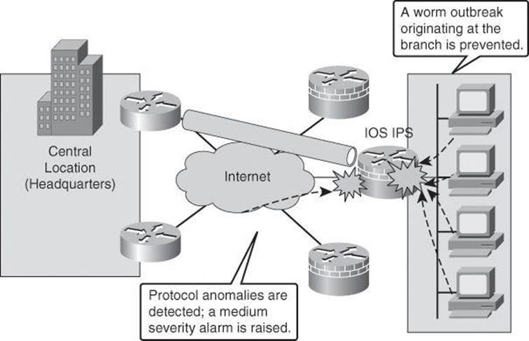
Figure 11-11. Cisco IOS IPS Protecting Against an Inside Attack
Signatures
Many of the features that make the Cisco IPS architecture effective are inherited by Cisco IOS IPS. Table 11-5 describes the features of Cisco IOS IPS–based signatures.
Table 11-5. Cisco IOS IPS Signature Features

Signature Files
As explained earlier in this chapter, a signature is a set of rules that an IDS and an IPS use to detect typical intrusive activity, such as DoS attacks.
IPS signatures are dynamically updated and posted to Cisco.com on a regular basis so that customers can access signatures that help protect their network from the latest known network attacks. The updates take the form of signature files, also known as signature packages or simply signature updates. Manual updates are also possible.
Cisco IPS devices use signature engines to load the signature files and scan signatures. Signatures that are contained within the signature packages are managed by various signature engines. The packages typically contain signature definitions for multiple engines.
Signature engines typically correspond to the protocol in which the signature occurs and look for malicious activity in that protocol. Each signature engine provides a common set of signature parameters that can be used to tune the sensitivity, scope, and actions of that particular signature engine, instead of making changes to individual signatures.
Signature Engines = Types of Interrogation
One way to think of signature engines is as types of interrogation. Each engine is an individual process that specializes in a particular type of interrogation. For example, one engine might specialize in IP headers, while another engine specializes in TCP headers, another in UDP headers, and yet another in ICMP traffic. Other engines look at application layer traffic such as SMTP or DNS. Data is processed in parallel by all the appropriate engines. Each engine specifies a set of available parameters to match malware traffic patterns.
A signature package has definitions for each signature it contains. After signatures are loaded and compiled onto a router running Cisco IOS IPS, IPS can begin detecting the new signatures immediately. Routers access signature definition information through a directory in flash that contains three configuration files—the default configuration, the delta configuration, and the Signature Event Action Processor (SEAP) configuration. SEAP is the control unit responsible for coordinating the data flow of a signature event.
Within a signatures package, signatures are categorized using signature engines and top-level categories. The first criterion to categorize signatures uses the basic and advanced signature categories. The basic signature category is appropriate for routers with less than 128 MB of available flash memory. The advanced signature category is appropriate for routers with more than 128 MB of available flash memory. Signatures are organized into signature microengines, explained further later in this section.
IOS IPS Default Category
Starting with Cisco IOS Release 15.0(1)M, in addition to the basic and advanced signature categories, there is a new category called IOS IPS default. This default category of signatures (including some lightweight signatures) is updated frequently by the Cisco signature team.
Signature files also come in different formats for the different methods to load them into the router’s flash. The file naming convention indicates which method to use. The following file naming conventions are available:
• Cisco Configuration Professional signature updates use the sigvX-SDM-S###.zip name format, where X is the IPS architecture version, and ### is the update ID, a number that increases with every new signature package.
• You can copy files from the CLI, in which case the naming conventions change: IOS-S###-CLI.pkg applies to CLI updates, where ### is the update ID.
Unified Signatures
The signatures became unified across all Cisco platforms with version 5.x of Cisco IOS IPS. Also, you will notice in the bullets regarding the signature updates the SDM reference in the naming convention. This is a legacy from the days of Cisco Security Device Manager, the predecessor to CCP.
Signature Management
Multiple enhanced features are available in Cisco IOS IPS to simplify the signature management process. The features include the following:
• Encrypted signature support: Digitally signed signatures allow for trusted authentication and nonrepudiation of the source.
• Lightweight signatures: Lightweight signatures allow loading of larger signatures sets, without consuming significant additional memory or reducing the memory that is consumed by an existing signature set.
• Direct download from Cisco.com capability: This feature allows an administrator to use the CLI to specify, download, and upgrade to new signatures posted for Cisco IOS routers directly from Cisco.com. An administrator can also configure the router through the CLI to receive future periodic signature downloads automatically to eliminate the manual maintenance efforts and costs of changing or tuning IPS signatures whenever a new update is posted.
• Tuning per top-level categories: Top-level signature categories classify signatures for easy grouping and tuning. Group-wide parameters, such as signature event actions, can be applied to a group instead of per signature.
• Signature tuning inheritance: This feature allows a network administrator to preserve the customization done on a signature when a signature package is updated. A local file includes locally tuned signature parameters, taking precedence over globally administered signature updates that may reset those parameters. Network administrators can either preserve the current configuration of signature actions or override the configuration with the default settings in future signature updates.
Examining Signature Microengines
A signature microengine (SME) is a component of an IDS and IPS sensor that supports a group of signatures that are in a common category. Each SME is customized for the protocol and fields that it is designed to inspect and defines a set of legal parameters that have allowable ranges or sets of values. The SMEs look for malicious activity in a specific protocol. Signatures can be defined for any of the supported SMEs by using the parameters offered by the supporting SME. Packets are scanned by the SMEs that understand the protocols contained in the packet.
Cisco SMEs implement parallel scanning. All the signatures in a given SME are scanned in parallel fashion, rather than serially. Each SME extracts values from the packet and passes portions of the packet to the regular expression engine. The regular expression engine can search for multiple patterns at the same time (in parallel). Parallel scanning increases efficiency and results in higher throughput.
When IDS (promiscuous mode) or IPS (inline mode) is enabled, an SME is loaded (or built) on to the router. When an SME is built, the router may need to compile the regular expression found in a signature. Compiling a regular expression requires more memory than the final storage of the regular expression. Be sure to determine the final memory requirements of the finished signature before loading and merging signatures.
Note
A regular expression is a systematic way to specify a search for a pattern in a series of bytes. As an example, a regular expression to be used to prevent data containing .exe or .com or .bat from crossing the firewall could look like this:
.*\.[Ee][Xx][Ee]|.*\.[Cc][Oo][Mm]|.*\.[Bb][Aa][Tt]
Note
For the list of currently supported SMEs, refer to Cisco.com. Specifically, see “Signature Microengines Overview and Lists of Supported Engines” at http://www.cisco.com/en/US/docs/ios-xml/ios/sec_data_ios_ips/configuration/15-0m/sec-cfg-ips.html#GUID-E402D400-0222-4206-8B2D-3B2368C7EABB
Table 11-6 summarizes the types of signature engines available in Cisco IOS IPS.
Table 11-6. Summary of Types of Supported Signature Engines
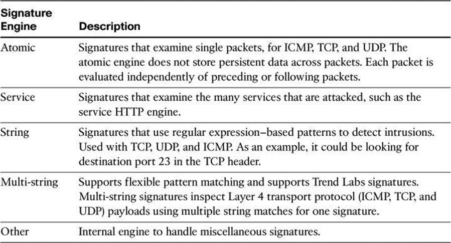
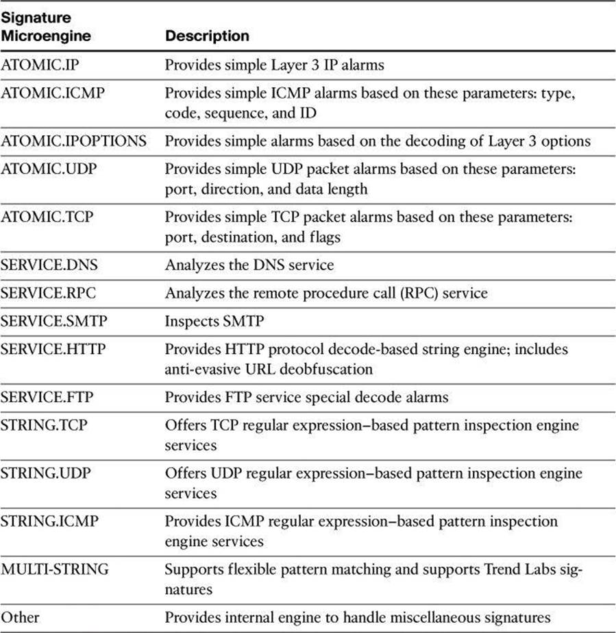
Table 11-7 provides more details on signature engines.
Table 11-7. Details on Signature Microengines
Signature Tuning
Router memory and resource constraints prevent a router from staging all Cisco IOS IPS signatures in such a way that they start utilizing router resources. When signature packages are copied into flash, the signatures are not yet staged in RAM. When Cisco IOS IPS is initialized, the signatures are loaded into the signature database. Loading refers to the process where Cisco IOS IPS parses the signature files and populates the signature database. However, it is the process of compiling, as shown in Figure 11-12, that stages the signatures and makes them utilize router resources. Compiling refers to the process where the parameter values from signatures are compiled into a regular expression table.
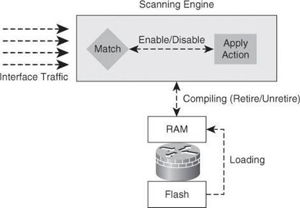
Figure 11-12. Signatures Interactions with Cisco IOS
When signatures are compiled, they are not scanned on a serial basis. A parallel signature scanning engine is used to scan for multiple patterns within a signature engine at any given time, and match intrusion activity for traffic flows that are processed by the router’s interfaces. If traffic matches those patterns, an action is performed.
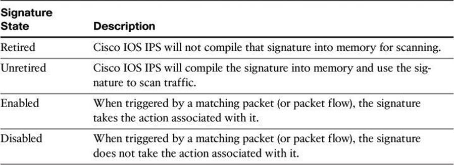
You can alter this process to preserve router resources and tune your intrusion prevention system. Cisco IOS IPS allows administrators to retire signatures, which prevents them from being compiled and using router resources. Similarly, unretiring signatures would compile them again. Retiring preserves the router’s resources.
The system also allows administrators to enable and disable signatures. An enabled signature performs the actions that are associated with the signature, while a disabled signature does not.
Table 11-8 provides a description of the different states of signatures.
Table 11-8. Signature States
Optimal Signature Set
By default, most signatures are retired to preserve router resources. The first level of tuning in Cisco IOS IPS environments is aimed at striking a balance between performance and IPS effectiveness. Relevant signatures should be unretired and enabled to increase the effectiveness of the system. When doing this, memory and computing resources should be closely monitored. There is no magic number or rule to design the appropriate configuration for your environment. Careful planning is required. You should start with the predefined basic and advanced signature definitions that are based on the hardware resources on the router, and build from there.
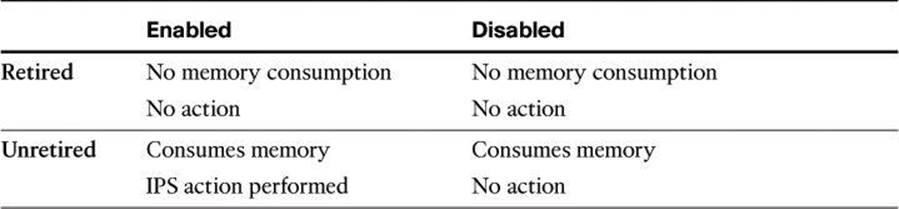
It is worth noting that disabling signatures does not preserve computing resources if the signature is not retired. An unretired disabled signature, similar to an unretired enabled signature, is still processed against inspected traffic by the scanning engine. The only difference is that the associated action will not be performed in the case of the disabled signature.
It is also worth noting that only unretired and successfully compiled signatures will take the action when they are enabled. When a signature is retired, even though it may be enabled, it will not be compiled and will not take the action that is associated with it. Also, when a signature is disabled, even though it may be unretired and successfully compiled, it will not take the action that is associated with it.
The combinations of signature compilations and states are outlined in Table 11-9.
Table 11-9. Combinations of Signature Compilations and States
The predefined Cisco IOS IPS basic and advanced signature categories contain an optimum combination of signatures for all standard memory configurations, providing a good starting point.
The following list summarizes the guidelines for planning an efficient and effective Cisco IOS IPS signature definition:
• The number of signatures that can be compiled depends on the free memory available on the router.
• For routers with 128 MB of flash, start with the basic signature category.
• For routers with 256 MB+ of flash, start with the advanced signature category.
• Retire risk-irrelevant signatures according to your needs.
• Monitor free memory when retiring or unretiring signatures.
• In restrictive policies, define a fail-closed action if signatures fail to compile. This setting instructs the router to drop all packets until the signature engine is built and ready to scan traffic. If this command is issued, one of the following scenarios occurs:
• If IPS fails to load the signature package, all packets are dropped—unless the user specifies an access control list (ACL) for packets to send to IPS.
• If IPS successfully loads the signature package, but fails to build a signature engine, all packets that are destined for that engine are dropped.
• If this command is not issued, all packets are passed without scanning if the signature engine fails to build.
• Disabled signatures are still scanned and processed, and will consume resources.
• Never unretire the “All” signature category.
Other signature tuning opportunities are outside the scope of this book. However, some guidelines and recommended practices are listed here. It is recommended that you tune signature parameters to customize the sensitivity, scope, response, and overall accuracy of your intrusion prevention system.
• Apply Cisco IOS IPS policies on interfaces for ingress traffic.
• Tune signature parameters to define the sensitivity, scope, response, and accuracy of signatures.
• Matching criteria (patterns, protocol parameters, and so on)
• Signature action
• Thresholds and counters
• Add or remove actions based on risk rating.
• Example: For an alarm-only signature, add a deny packet inline action if the risk rating is above a certain threshold.
• Create custom signatures for vulnerabilities and threats unique to your environment.
• Configure the router not to override tuned parameters in the next signature package update.
Monitoring IPS Alarms and Event Management
An important part of network security is the alarms generated by IPS. These alarms need to be collected and analyzed. In this section, we discuss the alarms and where they are sent.
Cisco IOS IPS Alarms Monitoring
Figure 11-13 shows how to use the Security Device Event Exchange (SDEE) protocol and a syslog-based approach to send Cisco IPS alerts. The sensor generates an alarm when an enabled signature is triggered. Alarms are stored on the sensor. A host can pull the alarms from the sensor using SDEE. Pulling alarms from a sensor allows multiple hosts to subscribe to the event “feed” to allow a host or hosts to subscribe on an as-needed basis.
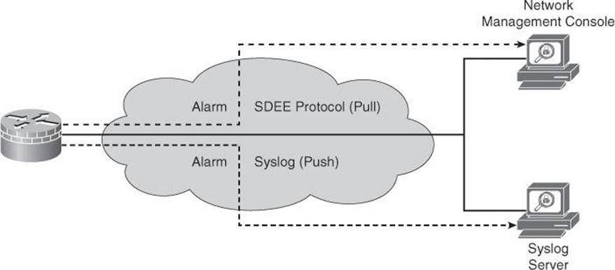
Figure 11-13. Support for SDEE and Syslog
The support for SDEE and syslog in the Cisco IOS IPS solution is as follows:
• Cisco IOS Software supports the SDEE protocol. When Cisco SDEE notification is enabled (by using the ip ips notify sdee command), by default 200 events can be stored in the event buffer, whose size can be increased to hold a maximum of 1000 events. When you disable Cisco SDEE notification, all stored events are lost. A new buffer is allocated when the notifications are reenabled.
• SDEE uses a pull mechanism. That is, requests come from the network management application, and the IDS and IPS router responds.
• SDEE becomes the standard format for all vendors to communicate events to a network management application.
• You must also enable HTTP or HTTPS on the router, using the ip http server command, when you enable SDEE. The use of HTTPS ensures that data is secured as it traverses the network.
• The Cisco IOS IPS router still sends IPS alerts via syslog.
When you use CCP, you can keep track of alarms that are common in SDEE system messages, including IPS signature alarms. The following is an example of an SDEE system alarm message:
%IPS-4-SIGNATURE:Sig:1107 Subsig:0 Sev:2 RFC1918 address
[192.168.121.1:137 ->192.168.121.255:137]
The preceding alarm was triggered by the fact that a packet with a private address, as listed in RFC 1918, traversed the IPS sensor.
Note
For a complete list of the Cisco IOS IPS system messages, refer to the “Interpreting Cisco IOS IPS System Messages” section in the Cisco IOS Security Configuration Guide, Release 12.4.
Event Management
Using SDEE and syslog, event monitoring can be accomplished at various levels, depending on the availability of local, enterprise, or global correlation and event management systems. In addition to the router’s buffers, the following management applications can be used to store a single router’s alarms, as also previously shown in Figure 11-5:
• Local event management and correlation
• Cisco Configuration Professional
• IPS Device Manager
• IPS Manager Express
• Enterprise event management and correlation
• Cisco Security Manager
• Third-party ecosystem partner SIEM systems
• Global event management and correlation
• Cisco Security Intelligence Operations (SIO)
IPS Manager Express
IPS Manager Express (IME) is a free application from Cisco that can manage alarms from up to 10 SDEE sources—either Cisco IPS Sensors or Cisco IOS IPS routers. Many of the features in IME work only with the IPS Sensors, and not with the Cisco IOS IPS routers.
Configuring Cisco IOS IPS Using Cisco Configuration Professional
Cisco IOS IPS allows you to manage intrusion prevention on routers that use Cisco IOS Software Release 12.3(8)T4 or later. Cisco Configuration Professional lets you control the application of Cisco IOS IPS on interfaces, import and edit signature files from Cisco.com, and configure the action that Cisco IOS IPS should take if a threat is detected.
Following are the configuration steps to deploy Cisco IOS IPS using CCP:
Step 1. Download the latest Cisco IOS IPS signature package to a local PC using Cisco Configuration Professional Auto Update.
Step 2. Launch the IPS Policies Wizard to configure Cisco IOS IPS.
Step 3. Verify that Cisco IOS IPS configuration and signatures are properly loaded.
Step 4. Perform signature tuning.
Step 5. Verify alarms.
The configuration scenario is shown Figure 11-14. Configure this branch router to enable Cisco IOS IPS on both inside and outside interfaces, enabling the advanced signature category. Then, you can perform basic tuning, unretiring signatures and changing the default action.
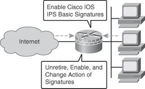
Figure 11-14. Cisco IOS IPS Configuration Scenario
Step 1: Download Cisco IOS IPS Signature Package
In the first step, you navigate to the Auto Update screen. From the Cisco Configuration Professional Home page, click Configure, choose Security > Intrusion Prevention in the left navigation pane, click the Edit IPS tab on the right, and then click Download in the left column. If SDEE notification is not enabled on the router, an Information dialog box appears, as shown in Figure 11-15. Click OK to enable SDEE notification.
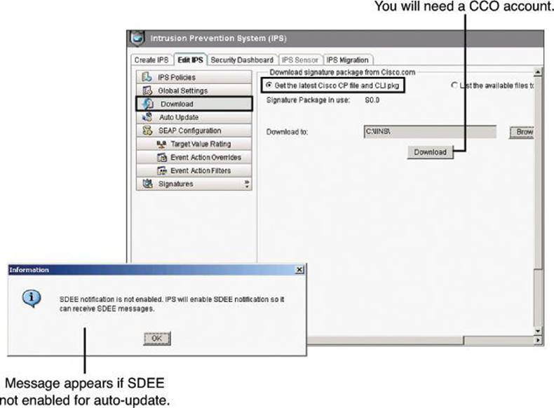
Figure 11-15. Downloading Signature Package Using CCP
Download the latest Cisco IOS IPS signature package to a local TFTP or FTP server. On the Download panel, click the Get the Latest Cisco CP File and CLI pkg radio button, as shown in Figure 11-15. Next, click the Browse button and select a directory on your local PC in which to save the downloaded files. You can choose the TFTP or FTP server root directory, which will be used later when deploying the signature package to the router. Next click Download, as shown in Figure 11-15.
When prompted to provide Cisco.com login credentials, enter your Cisco.com registered username and password.
CCP connects to Cisco.com, as shown in Figure 11-16, and starts to download both the CCP signature file (for example, sigv5-SDM-S353.zip) and the CLI signature pkg file (for example, IOS-S353-CLI.pkg) to the directory you selected in the previous step. After both files are downloaded, CCP prompts you to push the downloaded signature package to the router. Choose No if, as with our scenario, Cisco IOS IPS has not yet been initialized on the router.
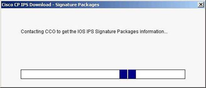
Figure 11-16. Updating the Cisco IOS IPS Signature Package
Step 2: Launch IPS Policies Wizard
After CCP downloads the latest Cisco IOS CLI signature package, go to the Create IPS tab to create the initial Cisco IOS IPS configuration, as shown in Figure 11-17 (Configure > Security > Intrusion Prevention > Create IPS). If prompted to apply changes to the router, click Apply Changes. Next, click Launch IPS Rule Wizard (which in fact launches the IPS Policies Wizard). An Information dialog box pops up to inform you that Cisco Configuration Professional needs to establish an SDEE subscription to the router to retrieve alerts. Click OK.
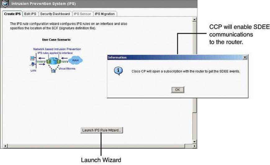
Figure 11-17. Creating an IPS Policy by Launching the IPS Policies Wizard in CCP
On the Select Interfaces screen of the IPS Policies Wizard, choose the interfaces on which you want to apply the Cisco IOS IPS rule by specifying whether the rule is to be applied to inbound traffic or outbound traffic, as shown in Figure 11-18. If you check both the inbound and the outbound boxes, the rule applies to traffic flowing in both directions. Click Next to continue.
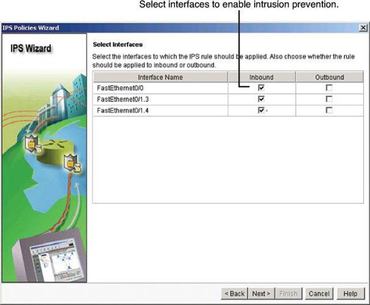
Figure 11-18. IPS Policies Wizard: Selecting the Interfaces
FastEthernet 0/0 Inbound and FastEthernet 0/1 Outbound
What would happen if you configured the IPS rules to be applied to FastEthernet 0/0 inbound and FastEthernet 0/1 outbound? You could get two alarms, one generated by the ingress rule and one by the egress rule.
On the Signature File and Public Key screen of the IPS Policies Wizard, you make the signature file available to the router. This is demonstrated in Figure 11-19. In the Signature File section, click the first radio button, Specify the Signature File You Want to Use with IOS IPS. Then click the ... button to open the Specify Signature File dialog box, in which you specify the location of the signature package file.
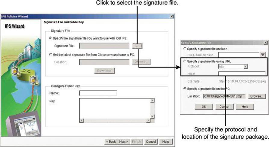
Figure 11-19. IPS Policies Wizard: Selecting the Signature File
You will need to make the previously downloaded signature file available via TFTP, FTP, and other options, such as having it resident on the local PC. In the Specify Signature File dialog box, choose the protocol and location URL. In this example, we are uploading the signature file from the local PC. When you are finished, click OK to return to the Signature File and Public Key screen.
Each change to the signature configuration is saved in the delta file. This file must be digitally signed with a public key. You can obtain a key from Cisco.com and copy and paste the information in the Name and Key fields. Public keys will be discussed in Chapter 12, “Fundamentals of Cryptography and VPN Technologies.”
Figure 11-20 shows realm-cisco.pub.key.txt entered in the Name field of the Configure Public Key section, with the appropriate public key string copied and pasted in the Key field. This public key can be downloaded from Cisco.com at http://download-sj.cisco.com/cisco/ciscosecure/ids/sigup/5.0/ios/realm-cisco.pub.key.txt.
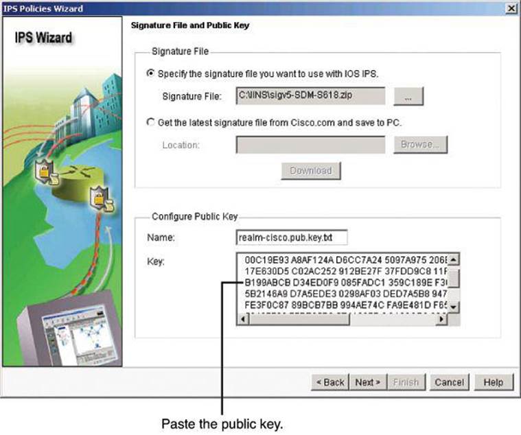
Figure 11-20. IPS Policies Wizard: Downloading and Installing Cisco’s Public Key
Click Next to continue.
In the next wizard screen, Config Location and Category, you specify a location in the router flash for storing the signature information that Cisco IOS IPS will use. This information consists of the signature file and the delta file that is created when changes are made to the signature information. Follow these steps, shown in Figure 11-21:
Step 1. In the Config Location and Category screen, select a location where the signature definition and configuration files will be stored by clicking the ... button to the right of the Config Location field.
Step 2. In the Add Config Location dialog box, choose the first option, Specify the Config Location on This Router, and then click the ... button to the right of the Directory Name field.
Step 3. In the Choose Folder dialog box, choose the router flash folder where the IPS files will be stored. If you want IPS files to be in their own folder, click on the New Folder button and give an intuitive name to the new folder. In our example, we called it IPS.
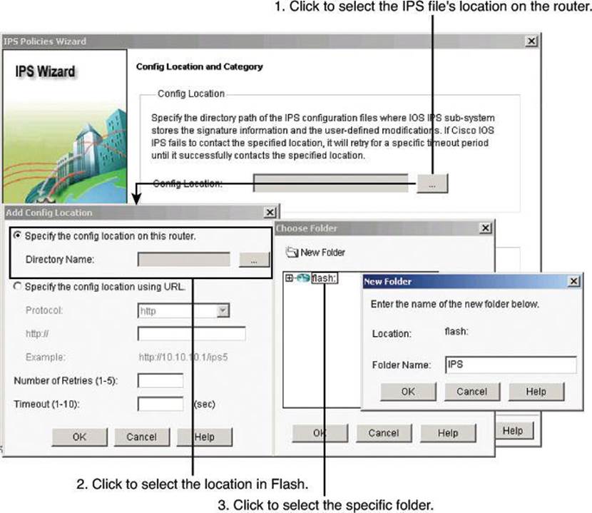
Figure 11-21. IPS Policies Wizard: Storing Signature Information
After you click OK in the various dialog boxes to return to the Config Location and Category screen of the IPS Policies Wizard, choose a signature category from the Choose Category drop-down list, shown in Figure 11-22, according to the amount of flash memory that is installed on the router. Because router memory and resource constraints may prevent the use of all the available signatures, there are two categories of signatures—basic and advanced. The basic category is appropriate for routers with less than 128 MB of available flash memory. The advanced category is appropriate for routers with more than 128 MB of available flash memory. The advanced category requires additional licenses to be obtained.
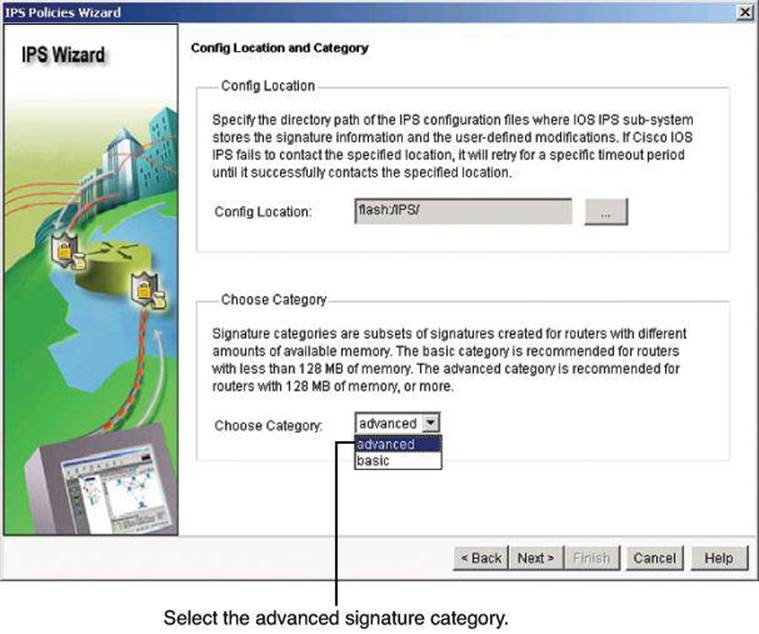
Figure 11-22. IPS Policies Wizard: Configuring Location and Signature Category
Note
If you have not activated the Cisco IOS IPS License, then installation of advanced signature packages will fail. Other signature packages can be installed without the license.
In this example, select advanced, since we have enough memory, and click Next.
The Summary screen, shown in Figure 11-23, provides a brief description of the tasks for the Cisco IOS IPS initial configuration. Click Finish on the Summary screen to deliver the configurations and signature package to the router.
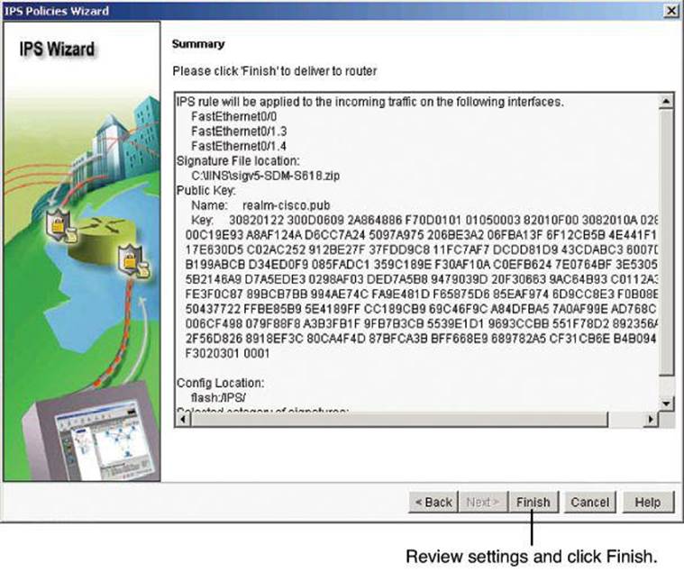
Figure 11-23. IPS Policies Wizard: Summary Configuration
Step 3: Verify Configuration and Signature Files
When the signatures are loaded, Cisco Configuration Professional then displays the Edit IPS tab (Configure > Security > Intrusion Prevention > Edit IPS) with the current configuration. Verify the configuration by checking which interface and in what direction Cisco IOS IPS is enabled.
On the Edit IPS tab, you can also enable or disable Cisco IOS IPS on an interface and view information about how Cisco IOS IPS is applied, by clicking IPS Policies as shown in Figure 11-24. If you enable Cisco IOS IPS on an interface, you can specify which traffic to examine for intrusion.
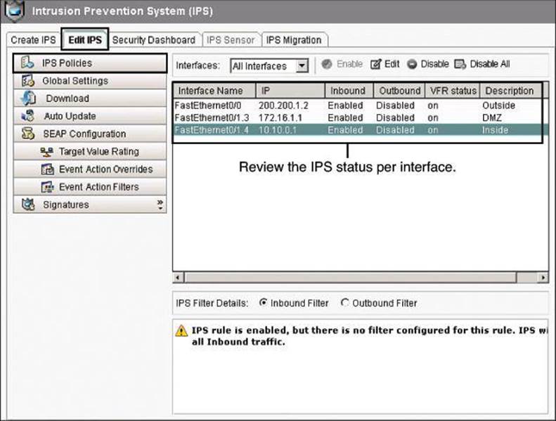
Figure 11-24. Reviewing IPS Configuration and Interface Status
On the Edit IPS tab, you can click Signatures to verify the signature numbers and start planning your resource preservation strategy based on the router model, as shown in Figure 11-25.
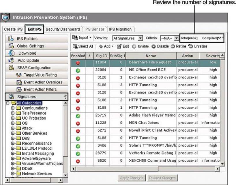
Figure 11-25. Reviewing IPS Signatures
Compiled Signatures
In Figure 11-25, notice the Sub-Sig ID column. When there are multiple ways for Cisco IPS to recognize the same kind of attack, all those signatures will have the same Signature ID number (Sig ID), but each will have a different Sub-Signature ID number (Sub-Sig ID).
Also notice the Compiled count in the upper-right corner of Figure 11-25. This represents the number of unretired signatures. “Compiled” and “unretired” are synonyms in this context.
Step 4: Perform Signature Tuning
The most basic level of Cisco IOS IPS tuning manages resource preservation. Navigate to Configure > Security > Intrusion Prevention > Edit IPS > Signatures to tune the signatures, as shown in Figure 11-26. To find specific signatures or groups of signatures, you can use these filtering mechanisms:
• The signature tree enables you to filter the signature list on the right according to the type of signature that you want to view. First choose the branch for the general type of signature that you want to display. The signature list displays the configured signatures for the type that you chose. If a plus (+) sign appears to the left of the branch, there are subcategories that you can use to refine the filter. Click the + sign to expand the branch and then choose the signature subcategory that you want to display. If the signature list is empty, there are no configured signatures available for that type. For example:
• To display all attack signatures, click the Attack branch folder.
• To see the subcategories that you can use to filter the display of attack signatures, click the + sign next to the Attack folder.
• To see denial of service signatures, click the DoS folder.
• The View By and Criteria drop-down lists enable you to filter the display according to the types of signatures that you want to view. First choose the criteria in the View By drop-down list, and then choose the value for that criteria in the Criteria drop-down list. For example, if you choose Engine in View By, Criteria changes to Engine, and you can choose among the available engines, such as ATOMIC.ICMP and SERVICE.DNS. If you choose Sig ID or Sig Name in the View By drop-down list, you must enter a value in the Criteria field.
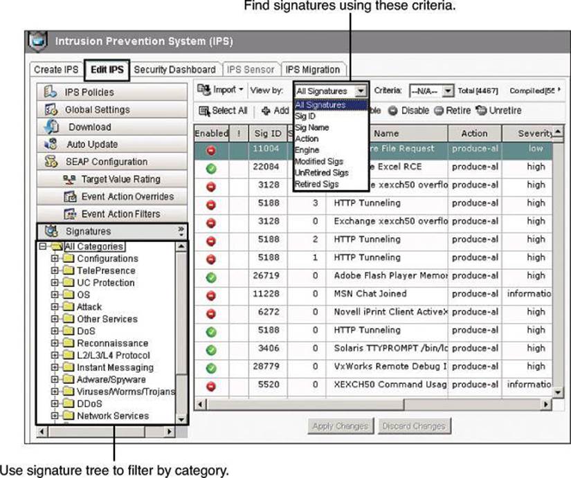
Figure 11-26. Looking at the Signatures
To retire or unretire and enable or disable signatures, select the signatures and then click Enable, Disable, Retire, or Unretire, based on your needs and the resources available on the router.
Notice how the status changes in the Enabled or the Retired column. A yellow icon appears for the signature in the column next to Enabled, as shown in Figure 11-27. The yellow icon means that changes have been made to the signature but have not been applied. Click Apply Changes to make the changes take effect.
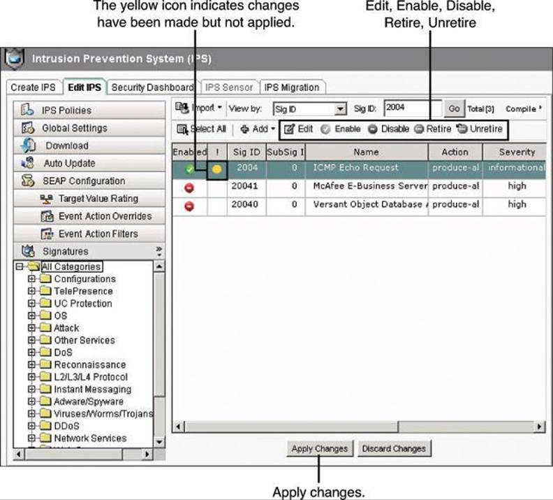
Figure 11-27. Enable, Disable, Retire, or Unretire Signatures
To change the action that is associated with a signature, select the signature, right-click and choose Actions, and then check or uncheck the check boxes next to the actions to choose the actions to be associated with this signature, as shown in Figure 11-28.
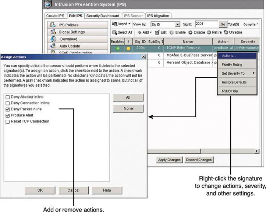
Figure 11-28. Changing Action of Signatures
Following is a summary of the options available in the context menu when you right-click a signature:
• Actions: Click to choose the actions to be taken when the signature is matched.
• Set Severity To: Click to set the severity level of a signature to high, medium, low, or informational.
• Restore Defaults: Click to restore the default values of the signature.
• Remove Filter: Click to remove a filter applied to the signature.
• NSDB Help: Click to display help on the Network Security Database (NSDB) (requires a Cisco.com account).
Signature Actions
With Cisco IOS IPS, protection can be done in two ways. You can enable explicit protection on specific signatures, as shown in Figure 11-28, or it can be enabled implicitly using Event Action Overrides to protect whenever the risk rating is at or above a specified threshold. Determining which signatures should have blocking actions can be a daunting task, so the simpler alternative is to use Event Action Overrides, which uses Event Risk Rating (ERR) to make the decision on your behalf.
Cisco IOS IPS Configuration = XML
When you apply changes to the Cisco IOS IPS configuration, you will not see a command preview in CCP. This is due to the fact that Cisco IOS IPS configuration is stored in XML documents in flash, and not in the running config. The files are in flash:/IPS, as you specified from the Config Location and Category screen of the IPS Policies Wizard.
Step 5: Verify Alarms
Cisco Configuration Professional can be used as an event viewer for Cisco IOS IPS alarms. You can view the log by navigating to Monitor > Security > IPS Status and clicking the IPS Signature Statistics tab. (The IPS Status pane also includes an IPS Alert Statistics tab, which is discussed a bit later in this section.)
Figure 11-29 illustrates the contents of the IPS Signature Statistics tab. Statistics are displayed for each enabled signature in the Cisco IOS IPS configuration. The top of the tab displays signature totals to provide a snapshot of the signature configuration. The following totals are provided:
• Total Signatures
• Total Enabled Signatures
• Total Retired Signatures
• Total Compiled Signatures
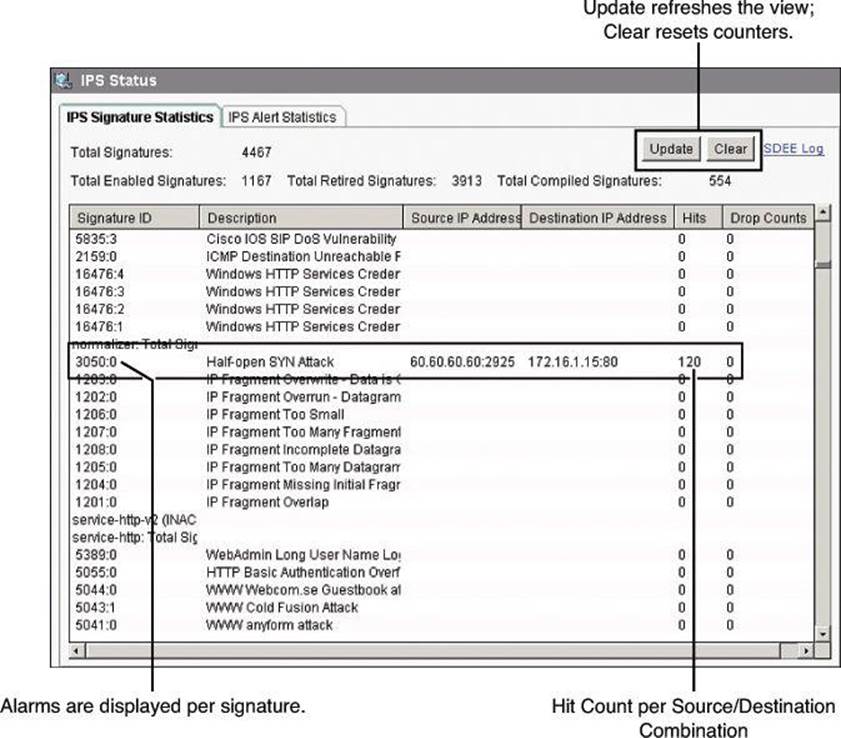
Figure 11-29. Monitoring IPS Signature Statistics from CCP
The statistics table displays alarm counters per signature. The table includes the signature ID, signature description, number of hits or times the signature has been matched, and a drop count that represents the number of times the packet has been dropped due to this event. If a packet that matches a signature arrives, the source and destination IP addresses are listed as well.
The table is not updated automatically. You can click Update to check for and include the latest signature statistics. You can also click Clear to set all signature statistic counters to 0.
More alarm detail can be observed by displaying the SDEE log. Click the SDEE Log link, shown in Figure 11-30, of the IPS Signature Statistics tab to display the log. CCP automatically navigates to Monitor > Router > Logging and displays the SDEE Message Log tab, shown in Figure 11-30. Some of the alarms relate to the status of the Cisco IOS IPS service, while some others relate to Cisco IOS IPS service error conditions. Click the SDEE Messages drop-down menu to filter and display Alerts only.
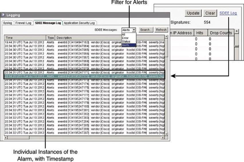
Figure 11-30. Monitoring IPS Alarms from CCP
The list includes all alarms in the router buffer, including the following components:
• Time: Timestamp for the individual alert
• Type: Alerts, Error, or Status entry
• Description: Includes event ID, signature IDs, risk rating, and other pieces of alarm-related information
The list is searchable. Clicking Search opens a search window, where you can choose a search type from the Search menu, enter the appropriate text in the Search field, and then click Find to display matching log entries.
The search types include the following:
• Source IP Address
• Destination IP Address
• Text
Searches are not case sensitive.
The IPS Alert Statistics tab, on the other hand, displays a view from the alerts and risk rating perspective. The panel displays alert statistics in a color-coded format for easy recognition. The top part of the screen shown in Figure 11-31 displays a legend that explains the use of colors in the display.
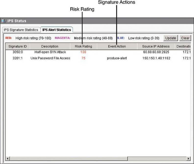
Figure 11-31. IPS Signature Statistics
The alert color coding is presented in Table 11-10.
Table 11-10. Alert Color Coding
By clicking a column heading, you sort the display based on the values of that parameter. For example, click the Signature ID heading to sort the display in ascending or descending numerical order of signature IDs. Each column is described in the following list:
• Signature ID: Numerical signature identifier.
• Description: Description of the signature.
• Risk Rating: Value between 0 and 100 that represents a numerical quantification of the risk associated with a particular event on the network.
• Event Action: Action that Cisco IOS IPS takes when an event matching the signature occurs.
• Source IP Address: The IP address from which the packet originated.
• Destination IP Address: The IP address to which the packet was addressed. If the packet is malicious, the destination IP address can be considered the target.
• Hits: Number of matching packets.
• Drop Count: The number of matching packets dropped.
• Engine: The signature engine associated with the signature.
Configuring Cisco IOS IPS Using the CLI
To use the command-line interface (CLI) to specify an IPS rule, use the ip ips name name command in global configuration mode as follows:
router(config)# ip ips name sdm_ips_rule
In the preceding command, the IPS rule had been created using CCP. Commands created by CCP appear in the CLI with the notation “sdm,” for Security Device Manager, which was the predecessor to CCP.
To specify the location of the IPS configuration, use the ip ips config location location global configuration command, as demonstrated here:
router(config)# ip ips config location flash:/ips/retries 1
To specify the method of event notification, use the ip ips notify global configuration command. The following is an example of event notification sent using SDEE:
router(config)# ip ips notify SDEE
Note
Examples in this section that deal with Cisco IOS IPS CLI configuration assume that the signature files are already on the router.
To configure the router to support the default basic signature set, use the ip ips signature-category global configuration command as follows:
Router(config)# ip ips signature-category
Router(config-ips-category)# category all
Router(config-ips-category-action)# retired true
Router(config-ips-category-action)# exit
Router(config-ips-category)# category ios_ips basic
Router(config-ips-category-action)# retired false
To apply an IPS rule to an interface, use the ip ips ips_rule_name command in interface configuration mode as demonstrated here:
router(config)# interface FastEthernet0/0
router(config-if)# ip ips sdm_ips_rule in
You should also consider turning on packets virtual reassembly on the sensing interface. Virtual Fragment Reassembly (VFR) enables the Cisco IOS Firewall to examine out-of-sequence fragments and reorder the packets into the correct order. It examines the number of fragments from a same single IP address. When VFR is enabled on the Cisco IOS Firewall, it creates the appropriate dynamic ACLs, thereby protecting the network from various fragmentation attacks. To enable VFR on an interface, use the ip virtual-reassembly command in interface configuration mode, as demonstrated here:
Router(config)# interface FastEthernet0/0
Router(config-if)# ip virtual-reassembly
Example 11-1 provides a combined view of the commands shown in the preceding paragraphs.
Example 11-1. Cisco IOS IPS CLI Configuration
Router(config)# ip ips name sdm_ips_rule
Router(config)# ip ips config location flash:/ips/ retries 1
Router(config)# ip ips notify SDEE
!
Router(config)# ip ips signature-category
Router(config-ips-category)# category all
Router(config-ips-category-action)# retired true
Router(config-ips-category-action)# exit
Router(config-ips-category)# category ios_ips basic
Router(config-ips-category-action)# retired false
!
Router(config)# interface Ethernet0/0
Router(config-if)# ip ips sdm_ips_rule in
Router(config-if)# ip virtual-reassembly
Use the show ip ips configuration command to display additional configuration data that is not displayed with the show running-config command. Example 11-2 shows some sample output from the show ip ips configuration command.
Example 11-2. show ip ips configuration Command Output
Router# show ip ips configuration
IPS Signature File Configuration Status
Configured Config Locations: flash:/ips/
Last signature default load time: 04:39:33 UTC Oct 19 2011
Last signature delta load time: 04:41:43 UTC Oct 19 2011
Last event action (SEAP) load time: -none-
General SEAP Config:
Global Deny Timeout: 3600 seconds
Global Overrides Status: Enabled
Global Filters Status: Enabled
IPS Auto Update is not currently configured
IPS Syslog and SDEE Notification Status
Event notification through syslog is enabled
Event notification through SDEE is enabled
IPS Signature Status
Total Active Signatures: 295
Total Inactive Signatures: 4008
IPS Packet Scanning and Interface Status
IPS Rule Configuration
IPS name sdm_ips_rule
IPS fail closed is disabled
IPS deny-action ips-interface is false
Obsolete tuning is disabled
Regex compile threshold (MB) 14
Interface Configuration
Interface FastEthernet0/0
Inbound IPS rule is sdm_ips_rule
Outgoing IPS rule is not set
Interface FastEthernet0/1
Inbound IPS rule is sdm_ips_rule
Outgoing IPS rule is not set
IPS Category CLI Configuration:
Category all:
Retire: True
Category ios_ips basic:
Retire: False
You could use the show ip ips all command (not shown here) to display additional configuration data that is not displayed with the show ip ips configuration command.
Use the show ip ips interface command to display interface configuration data. Example 11-3 displays output from the show ip ips interface command, revealing that the inbound IPS audit rule sdm_ips_rule is applied to FastEthernet 0/0 and FastEthernet 0/1. There is no rule applied for outgoing traffic on either interface.
Example 11-3. show ip ips interfaces Command Output
Router# show ip ips interfaces
Interface Configuration
Interface FastEthernet0/0
Inbound IPS rule is sdm_ips_rule
Outgoing IPS rule is not set
Interface FastEthernet0/1
Inbound IPS rule is sdm_ips_rule
Outgoing IPS rule is not set
In Example 11-4, the output from the show ip ips signature count command displays summary signature information. The output shows the signature update ID, as well as the number of total, enabled, retired, compiled, and obsolete signatures. Remember that “compiled” means unretired.
Example 11-4. show ip ips signature count Command Output
Router# show ip ips signature count
Cisco SDF release version S594.0
Trend SDF release version V0.0
...
<output omitted>
...
Total Signatures: 4303
Total Enabled Signatures: 1218
Total Retired Signatures: 4008
Total Compiled Signatures: 295
Total Obsoleted Signatures: 13
Total Disallowed Signatures: 3
.
.
The router will also generate system log messages, providing an additional tool to monitor the health of the IPS feature. The following message is displayed when an IPS signature engine has been built and is ready to scan packets:
%%IPS-6-ENGINE_READY:SERVICE.HTTP – 183136 ms - packets for this engine will be
scanned
The following message is displayed when packets are being dropped due to a failed IPS module, when the ip ips fail closed command is configured. The ip ips fail closed command implements a restrictive fail-closed policy when the Cisco IOS IPS feature fails.
%IPS-5-PACKET_DROP:SERVICE.DNS – packets dropped while engine is building
The following message, discussed previously in this chapter, is displayed when an IPS signature has been triggered. The signature and subsignature IDs are shown. In this particular example, the alarm is related to a potential spoofing attack, as explained earlier.
%IPS-4-SIGNATURE:Sig:1107 Subsig:0 Sev:2 RFC1918 address [192.168.121.1:137
->192.168.121.255:137]
Use the show ip ips statistics command to show a global view of signatures that have triggered, along with valuable information such as the number of packets checked per signature, the number of alarms triggered per signature, and the number of packet drops per signature. The output ofExample 11-5 also shows the number of interfaces enabled for Cisco IOS IPS.
Example 11-5. show ip ips statistics Command Output
Router# show ip ips statistics
Signature statistics [process switch:fast switch]
signature 3041:0: packets checked [0:4] alarmed [0:4] dropped [0:0]
signature 3040:0: packets checked [0:1] alarmed [0:1] dropped [0:0]
signature 6062:1: packets checked [0:1] alarmed [0:1] dropped [0:0]
signature 6054:0: packets checked [0:3] alarmed [0:3] dropped [0:0]
Interfaces configured for ips 1
Session creations since subsystem startup or last reset 10101
Current session counts (estab/half-open/terminating) [15:764:0]
Maxever session counts (estab/half-open/terminating) [22:1182:0]
Last session created 00:00:08
Last statistic reset never
TCP reassembly statistics
received 2 packets out-of-order; dropped 0
peak memory usage 1 KB; current usage: 0 KB
Use the show ip sdee alerts command to see a detailed view of the alarm log, as shown in Example 11-6.
Example 11-6. show ip sdee alerts Command Output
router# show ip sdee alerts
Alert storage: 200 alerts using 96000 bytes of memory
SDEE Alerts
SigID Sig Name SrcIP:SrcPort DstIP:DstPort VRF
or Summary Info
1: 3040:0 TCP NULL Packet 172.17.44.101:36044 10.5.5.5:25 NONE
2: 3041:0 TCP SYN/FIN Packet 172.17.44.101:52623 10.5.5.5:25 NONE
3: 6054:0 DNS Version Request 172.17.44.101:4745 172.17.22.103:53 NONE
4: 6062:1 DNS Authors Request 172.17.44.101:4756 172.17.22.103:53 NONE
Summary
This chapter described how intrusion detection system (IDS) and intrusion prevention system (IPS) technology embedded in Cisco host- and network-based IDS and IPS solutions fights malware in real time. More precisely, you have learned how
• Cisco IOS IPS prevents intrusion by comparing traffic against the signatures of known attacks. A signature is a set of rules that an IDS and an IPS use to detect typical intrusive activity and how these files can be updated manually or automatically. A public key is required to use digitally signed signature files.
• Signatures can be retired or unretired, enabled or disabled.
• Cisco IOS IPS alarms are communicated using SDEE and syslog.
• The easiest way to configure Cisco IOS IPS on the router or security device is to click the Launch IPS Rule Wizard button in Cisco Configuration Professional to launch the IPS Policies Wizard.
• Cisco Configuration Professional, which includes comprehensive options for configuring IPS and for signature tuning, can also be used to manage Cisco IOS IPS events.
• CCP tools can be used to monitor IPS operations.
References
For additional information, refer to these resources.
Cisco.com Resources
“Cisco IOS IPS Q&A,” http://www.cisco.com/en/US/prod/collateral/iosswrel/ps6537/ps6586/ps6634/prod_qas0900aecd806fc530.html
Cisco IOS Security Configuration Guide, Release 12.4, “Configuring Cisco IOS Intrusion Prevention System (IPS),” http://www.cisco.com/en/US/docs/ios/security/configuration/guide/12_4/sec_12_4_book.html
Cisco Security Information Event Management Deployment Guide, http://www.cisco.com/en/US/solutions/collateral/ns340/ns414/ns742/ns982/sbaSIEM_deployG.pdf
“Getting Started with IOS IPS ![]() A Step-by-Step Guide,” http://www.cisco.com/en/US/prod/collateral/iosswrel/ps6537/ps6586/ps6634/prod_white_paper0900aecd805c4ea8.html
A Step-by-Step Guide,” http://www.cisco.com/en/US/prod/collateral/iosswrel/ps6537/ps6586/ps6634/prod_white_paper0900aecd805c4ea8.html
“Intrusion Prevention System,” http://www.cisco.com/go/ips
General IDS/IPS Resource
SearchSecurity.com, http://searchsecurity.techtarget.com/
Review Questions
Use the questions here to review what you learned in this chapter. The correct answers are found in the Appendix, “Answers to Chapter Review Questions.”
1. Which two modes of IPS operation are currently available with Cisco IDS and IPS solutions?
a. Out-of-band
b. Promiscuous
c. Multicasting
d. Inline
2. IDS solutions are typically related to inline deployment of sensors. True or false?
a. True
b. False
3. Which general patterns of misuse do IDS and IPS technologies look for? (Choose all that apply.)
a. Atomic pattern
b. Molecular pattern
c. Instrusive nonces
d. Composite (compound) pattern
e. Composition pattern
4. You need to customize signatures on Cisco IPS devices to detect ICMP ping exploits packet by packet. Which signature microengine should you use?
a. Service
b. Multi-string
c. Atomic
d. Sub-atomic
5. Which of the following are a type of IDS or IPS sensor? (Choose all that apply.)
a. Signature based
b. Policy based
c. Transgression based
d. Anomaly based
6. Match the technology with its definition?
a. Signature-based IPS
b. Policy-based IPS
c. Reputation-based IPS
d. Anomaly-based IPS
1. Normal behavior typically defined based on traffic patterns, traffic and protocol mix, traffic volumes, and other criteria
2. Typically implemented in the form of white lists or black lists
3. Can produce false positives because certain normal network activity can be mis-interpreted as malicious activity
4. Similar to implementing a restrictive firewall policy
7. What is a signature engine?
a. A set of rules that an IDS and an IPS use to detect typical intrusive activity
b. A full-feature intrusion prevention tool located in the core network fabric device
c. An internal security service module that provides dedicated CPU and memory to offload intrusion prevention processing.
d. A component of an IDS and IPS sensor that supports a group of signatures in a common category
8. Which IPS card could integrate into an ISR router?
a. Cisco IDSM-2
b. Cisco ASA AIP SSM
c. Cisco IPS AIM
d. Cisco IPS 4200 Series Sensor
9. What is an IPS signature?
a. A message digest encrypted with the sender’s private key
b. A set of rules used to detect typical intrusive activity
c. A binary pattern specific to a virus
d. An appliance that provides anti-x services
10. Compiling a regular expression found in a signature requires more memory than the final storage of the regular expression. True or false?
a. True
b. False
11. Which two choices are examples of techniques used to mitigate an evasion attack?
a. Data normalization
b. Botnet detection
c. TCP intercept
d. Session reassembly
e. False positive mitigation
12. Cisco IOS IPS supports risk-based signature tuning using Cisco Event Risk Rating. True or false?
a. True
b. False
13. The signature package named sigv5-SDM-S592.zip is an example of what type of signature package in Cisco IOS IPS?
a. Cisco Configuration Professional signature package
b. CLI signature package
c. Basic signature package
d. Advanced signature package
e. Default signature package
14. You are tuning IPS signatures using Cisco Configuration Professional and see a yellow icon next to the signature ID. What is the reason for this icon?
a. The signature is a candidate for false positives.
b. The signature is categorized with the wrong microengine.
c. You need to click Apply.
d. You need to enable the signature.
e. The signature is disabled and you need to unretire it.
15. Which statement is true about this Cisco IOS IPS syslog message?
%IPS-5-PACKET_DROP:SERVICE.DNS – packets dropped while engine is building
a. A fail-closed strategy is configured.
b. The service.dns microengine is disabled.
c. Packets are blocked by the action of a signature matching the traffic pattern.
d. An inline deployment option is being used.
All materials on the site are licensed Creative Commons Attribution-Sharealike 3.0 Unported CC BY-SA 3.0 & GNU Free Documentation License (GFDL)
If you are the copyright holder of any material contained on our site and intend to remove it, please contact our site administrator for approval.
© 2016-2026 All site design rights belong to S.Y.A.