Implementing Cisco IOS Network Security (IINS) Foundation Learning Guide, Second Edition (2013)
Part II: Protecting the Network Infrastructure
Chapter 3. Network Foundation Protection and Cisco Configuration Professional
In this chapter, you learn about Cisco IOS Network Foundation Protection (NFP) as a framework for infrastructure protection, all its components, and commonly used countermeasures as found in Cisco IOS devices. You also learn how to use Cisco Configuration Professional (CCP) to implement security controls on Cisco IOS routers.
More precisely, you learn how to do the following:
• Categorize common threats against the network infrastructure
• Describe Network Foundation Protection as a framework to develop and implement security controls to protect the network infrastructure
• List and compare security controls that protect the control plane
• List and compare security controls that protect the data plane
• List and compare security controls that protect the management plane
• Articulate the features and benefits of CCP, describing its requirements and installation options
• Demonstrate the CCP GUI, showcasing the most relevant options and features
• Describe the unique components of CCP that are used for effective security policy deployment and configuration
• Describe and implement the One-Step Lockdown and audit features found on CCP
Threats Against the Network Infrastructure
A key element in the overall security posture of an organization is the security of the network infrastructure. The network infrastructure is the foundation that is built with routers, switches, and other equipment that provides the fundamental network services to keep a network running. The infrastructure is often the target of denial of service (DoS) and other attacks that can directly or indirectly disrupt the network operation. In order to ensure the availability of the network, it is critical to implement the security tools and best practices that help protect each network element and the infrastructure as a whole.
Cisco Network Foundation Protection (NFP) provides an umbrella strategy for infrastructure protection by encompassing Cisco IOS security features.
The current network environment is complex, as networking devices offer a feature-rich set of services to cater to a variety of business needs. Business continuity requires security features and services for both network devices and infrastructure, thus ensuring the availability of the network devices under all circumstances.
Because connecting to the Internet is imperative, network devices and infrastructure are exposed to many risks and threats. Deploying security best practices helps secure the network foundation by protecting network elements and their interactions. In Internet and cloud computing environments, this means distrusting every packet and implementing policies that are aimed at categorizing traffic. Different traffic classes are then processed under different policies to ensure not only proper forwarding, but also dropping suspicious traffic, thus protecting the network devices themselves.
Table 3-1 lists some of the common threats to the network infrastructure. These threats are used not only to disrupt service via DoS attacks and routing protocol exploits, but also to create confidentiality exposure via trust exploitation attacks.
Table 3-1. Common Issues for Network Infrastructure
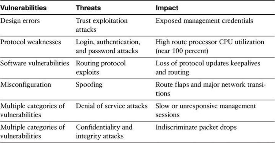
These threats exploit known vulnerabilities such as protocol weaknesses. For instance, the absence of confidentiality mechanisms in Telnet and certain versions of Simple Network Management Protocol (SNMP) can expose passwords and community names to malicious attackers. Unknown OS/software vulnerabilities can also be exploited using zero-day attacks. This exploitation can occur with software bugs and weaknesses, sometimes found in the operating systems of network devices.
The impact of these exploits and incidents is at the core of business operations. High resource utilization slows down network devices, and can even bring them down. Routing protocol operations can be disrupted, causing connectivity problems for all kinds of traffic. The problem is augmented when management sessions are slowed down in such a way that fixing the problem becomes a challenge.
The following are some of the symptoms and impact of network infrastructure security incidents:
• High route processor CPU utilization (near 100 percent)
• Loss of line protocol keepalives and routing protocol updates, leading to route flaps and major network transitions
• Slow or completely unresponsive interactive sessions via the CLI, due to high CPU utilization
• Route processor resource exhaustion, making resources such as memory and buffers unavailable for legitimate IP data packets
• Packet queue backup, leading to indiscriminate drops (or drops due to lack of buffer resources) of other incoming packets
It is important to apply a structured approach to network infrastructure protection. Different threats exploit different vulnerabilities in different functional areas of the network. As an example, spoofing attacks are commonly used to power DoS attacks from the external network, to exhaust edge device resources and link bandwidth. On more internal security domains, such as server farms and the campus access layer, Layer 2 attacks are typically aimed at trust exploitation and information theft using man-in-the-middle mechanisms.
Deploying the right policy and feature to the appropriate device is critical to the effective mitigation of these threats.
Cisco NFP Framework
To understand Cisco NFP architecture, it is important to understand the basics of the architecture of devices with routing capabilities. A router can be logically divided into three functional components or planes:
• Data plane
• Management plane
• Control plane
Most traffic travels through the router via the data plane. However, the route processor must manage certain packets, such as routing updates, keepalives, and network management. This traffic is often referred to as control and management plane traffic. The management plane, however, is considered separate from a functional perspective, in order to define different protection mechanisms to management traffic. In other words, the control and data planes use the central resources (CPU, memory, and so on) in Cisco network devices more intensely than does the management plane. This is depicted in Figure 3-1 by grouping them inside the same segmented lines. The data plane is typically processed in a fast-switching cache using distributed processing or in high-priority, process-independent code in the kernel.
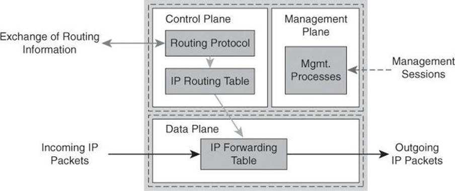
Figure 3-1. Device Planes
From the perspective of network traffic, a similar classification applies:
• Data plane packets: End-station, user-generated packets that are always forwarded by network devices to other end-station devices. From the perspective of the network device, data plane packets always have a transit destination IP address and can be managed by normal, destination IP address–based forwarding processes. Data plane packets are typically processed in a fast-switching cache.
• Control plane packets: Network device–generated/received packets that are used for the creation and operation of the network itself. From the perspective of the network device, control plane packets always have a receive destination IP address and are managed by the CPU in the network device route processor. Examples include protocols such as Address Resolution Protocol (ARP), Border Gateway Protocol (BGP), Open Shortest Path First (OSPF), and other protocols that hold the network together.
• Management plane packets: Network device–generated/received packets, or management station–generated/received packets, that are used to manage the network. From the perspective of the network device, management plane packets always have a receive destination IP address and are managed by the CPU in the network device route processor. Examples include protocols such as Telnet, Secure Shell (SSH), TFTP, SNMP, FTP, Network Time Protocol (NTP), and other protocols that are used to manage the device or network.
Differentiating Between Control Plane, Data Plane, and Management Plane
The control path code, such as routing protocols, runs on the control plane.
Data packets, such as user traffic, are forwarded by the data plane.
Management sessions to the device, such as Secure Shell, use the management plane.
To deploy a protection policy to protect the different operation planes of a router, a structured approach is needed. The three distinct functions will benefit from a combined effort to protect the device, but each one affects the router operations differently. The control plane affects the ability to route packets, because it implements routing protocol functions. The management plane affects the ability to configure and monitor the device, and eventually implement the desired security controls. The data plane affects the ability to forward traffic, a critical function that must be performed efficiently.
Packet overloads on the control plane of a router can slow down routing processes and, as a result, degrade network service levels and user productivity. Packets that traverse the control plane are those destined for the CPU of that router, as opposed to network endpoints. All packets entering the control plane are redirected by the forwarding plane.
Cisco NFP is an umbrella strategy encompassing Cisco IOS security features that provides the tools, technologies, and services that enable organizations to secure their network foundations. Cisco NFP helps to establish a methodical approach to protecting router planes, forming the foundation for continuous service delivery. NFP is not a single feature or technology, nor is it a single management tool or set of commands. It is a series of Cisco IOS features designed specifically to protect the device control plane by “locking down” services and routing protocols, protect the device data plane from malicious traffic, and protect the device management plane.
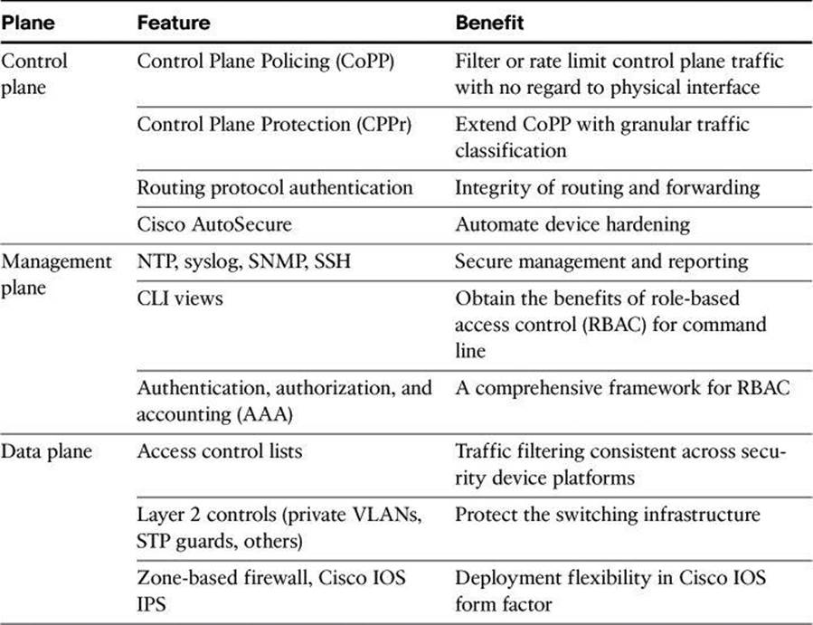
Cisco NFP is not a single feature of technology but rather is the deployment of a protection strategy that is based on several mechanisms that affect all three planes. Table 3-2 summarizes some of the protection techniques available under the Cisco NFP framework. This list is only a sample of the available tools, some of which will be described and demonstrated in this chapter. More information on Cisco NFP can be found at http://www.cisco.com/go/nfp. The NFP features listed in Table 3-2 will be explained in the upcoming chapters of this book.
Table 3-2. Some Components of Cisco NFP
Your network benefits from applying a structured approach to infrastructure protection using Cisco NFP. Figure 3-2 shows some of the benefits, which are explained next.
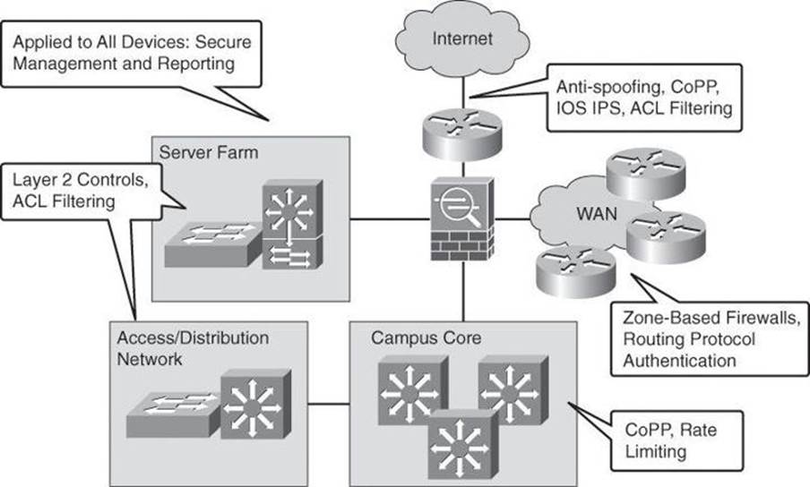
Figure 3-2. Some of Cisco NFP in a Network
Overall, network elements benefit from a strategy that is based on role-based access control (RBAC) at the management level. Role-based access control is a strategy that associates the authority to execute certain tasks with a specific privilege level, such as certain tasks that could be executed by senior network administrators but not by junior network administrators. A simple example would be that senior administrators are allowed to perform the show running-config command, but junior administrators are not allowed. Network devices are organizational assets like any other, and their exploitation can cause network outages, which could be prevented using proper RBAC deployment.
Secure management and reporting mechanisms, such as SSH and SNMPv3, could be planned across the board for all network devices for device hardening and management plane protection.
On the other hand, traditional perimeters such as the Internet edge benefit from antispoofing mechanisms such as infrastructure access control list (ACL) filtering, as well as external threat protection using Cisco IOS Intrusion Prevention System (IPS). These NFP countermeasures protect not only the device itself but also the assets that those devices connect to in the organization.
Internal perimeters, such as the WAN edge, benefit from a distributed approach to security countermeasures, in the form of zone-based firewalls. These firewalls benefit from the Cisco IOS form factor to leverage existing network elements, implementing access control and data plane security in multiple edge points of the WAN in a distributed fashion.
More internal perimeters, such as server farms and the access and distribution layers, benefit from Layer 2 controls that protect the switching infrastructure.
Cisco NFP does not prevent poor network design. In that sense, building some level of redundancy into the network design is critical to the deployment of some of the NFP features. There is no substitute to designing a layered approach to security, with redundant countermeasures at different levels. Physical security and high availability are also design building blocks that need to be in place for an NFP strategy to be effective.
It is critical to apply the proper selection of Cisco NFP features to the proper device, according to a risk management plan. In that sense, Cisco NFP also assumes that a security policy is in place.
In terms of operations, the network design should follow recommended practices in change management and disaster recovery procedures.
Control Plane Security
Control Plane Policing (CoPP) is a Cisco IOS feature designed to allow users to manage the flow of traffic that is managed by the route processor of their network devices. Ideally, traffic is fast-switched from one interface to the other, as represented by the arrow in Figure 3-3. However, sometimes traffic needs to be process-switched. The CPU is shared among three main functions: routing protocols, slow data plane, and management process. Excessive traffic to any of the three main functions can overwhelm the CPU and affect the other two functions. CoPP is designed to prevent unnecessary traffic from overwhelming the route processor and the slow data path.
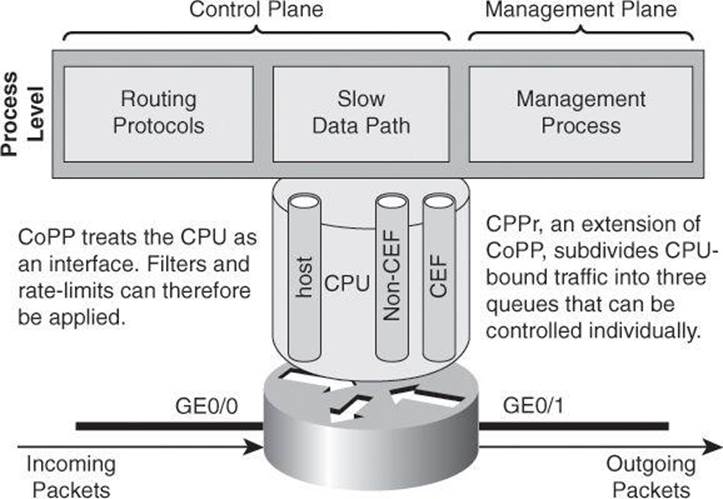
Figure 3-3. Goal of CoPP: Treat the CPU as an Interface
To protect the control plane on a router from DoS attacks, and to provide packet quality of service (QoS), the CoPP feature treats the control plane as an interface, as shown in Figure 3-3. Because the CoPP feature treats the control plane as a separate entity, a set of rules can be established and associated with the ingress and egress functions of the control plane, rules such as ACLs or rate limits.
These rules are applied only after the packet has been determined to have the control plane as its destination or when a packet exits the control plane. Thereafter, you can configure a service policy to prevent unwanted packets from progressing after a specified rate limit has been reached. For example, a system administrator can limit all TCP synchronization (SYN) packets that are destined for the control plane to a maximum rate of 1 Mbps.
Control plane security consists of implementing the following features:
• CoPP: CoPP lets users configure a QoS filter that manages the traffic flow of control plane packets to protect the control plane of Cisco IOS routers and switches against reconnaissance and DoS attacks.
• CPPr: CPPr is an extension of the policing functionality that the existing CoPP feature provides. CoPP allows QoS policing of aggregate control plane traffic that is destined to the route processor. The CPPr feature extends this policing functionality by allowing finer policing granularity by considering the CPU as three queues (subinterfaces), as shown in Figure 3-3: the host subinterface used by the routing and management processes, the Cisco Express Forwarding (CEF) subinterface, and the non-CEF subinterface.
• Control Plane Logging: CPPr lets you filter and rate-limit the packets that are going to the control plane of the router and discard malicious packets, or malformed packets or packets containing errors. The Control Plane Logging feature enables logging of the packets that these features drop or permit. The Control Plane Logging feature provides the logging mechanism that you need to deploy, monitor, and troubleshoot CoPP features efficiently.
CoPP
The CoPP feature provides the following benefits:
• Protection against DoS attacks that are targeted toward the network infrastructure by traffic flows and protocols that must be permitted, but where rate limiting offers substantial protection.
• Easier deployment. CoPP uses the existing Modular QoS CLI (MQC) infrastructure, which allows customers to preserve the existing interface configurations and add global control plane–specific commands to address security goals.
• A consistent implementation strategy across all Cisco hardware.
• Increased reliability, security, and availability of the network.
CPPr
Cisco CPPr extends the CoPP feature by enabling classification of the control plane traffic based on packet destination and information that is provided by the forwarding plane, allowing appropriate throttling for each category of packet. CPPr provides a finer policing. This is where you might add granularity to your policy, to accomplish tasks such as differentiating between Telnet, SSH, and HTTPS management traffic.
The functionality that is added with CPPr includes a traffic classifier, which intercepts traffic and classifies it into three control plane categories (queues, as shown in Figure 3-3). New port-filtering and queue-thresholding features have also been added. The port-filtering feature provides for policing of packets going to closed or nonlisted TCP and UDP ports, while queue thresholding limits the number of packets for a specified protocol that will be allowed in the control plane IP input queue.
As with CoPP, CPPr is implemented using Cisco IOS MQC, a highly flexible framework that allows users to create and attach traffic policies to interfaces. The Cisco MQC mechanisms are used by CPPr to define the classification and policing descriptions for its policies. In this way, in addition to the limited permit and deny actions that are associated with simple ACLs, specific packets may be permitted but rate-limited when using the MQC structure. For example, you may wish to permit certain Internet Control Message Protocol (ICMP) packet types, but rate limit them so that the route processor is not adversely impacted. This action adds tremendously to the capabilities and flexibility of developing and deploying a useable CPPr policy.
Key Concepts
What does Control Plane Protection provide you?
• Extends CoPP protection by providing mechanism for finer policing granularity for control plane traffic
• Allows rate limits for each traffic class individually
• Provides ease of configuration for control plane policies using modular policy CLI infrastructure
• Provides better platform reliability, security, and availability
• Provides CPU protection so it can be used for important jobs, such as routing
Traffic Classes
Before developing an actual CPPr policy, required traffic must be identified and separated into different classes. Multiple classification schemes can be used, but one recommended methodology involves classifying traffic into distinct groups that are based on relative importance. This approach can be illustrated with a simple classification example composed of four basic classes: critical, normal, undesirable, and default.
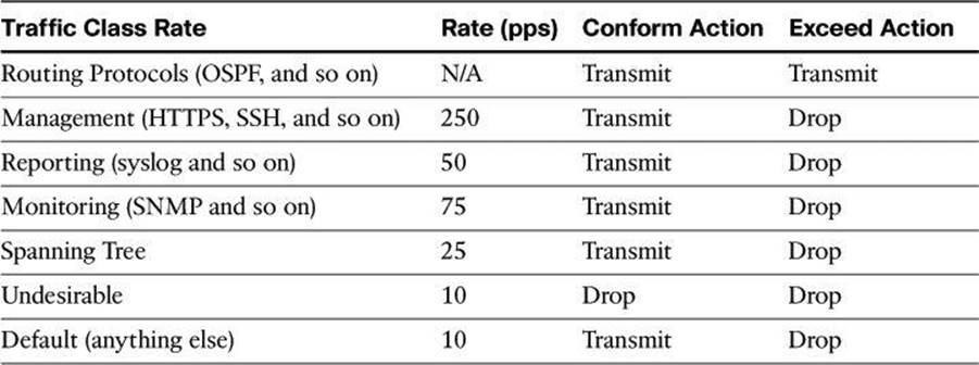
Table 3-3 illustrates a more complex classification scheme, along with the action to apply to each traffic class. This example uses seven different classes, which provides greater granularity and is more suitable for real-world environments. The actual number and type of classes that are needed for a given network may differ and should be selected based on local requirements, security policies, and a thorough analysis of baseline traffic.
Table 3-3. Example of a Complex CPPr Classification Scheme
The goal in this book is to introduce the complex topics of CoPP and CPPr. A deeper discussion of these topics can be found in the Cisco Press book CCNP Security SECURE 642-637 Official Cert Guide.
Routing Protocol Integrity
Other control plane security mechanisms are specific to routing protocols, such as routing protocol neighbor authentication. When configured, neighbor authentication occurs whenever neighbor routers exchange routing updates. This authentication ensures that a router receives reliable routing information from a trusted source.
Without neighbor authentication, unauthorized or deliberately malicious routing updates could compromise the security of your network traffic. A security compromise could occur if an unfriendly party diverts (rogue default gateways) or analyzes that traffic (man-in-the-middle attacks). For example, an unauthorized router could send a fictitious routing update to convince your router to send traffic to an incorrect destination.
The unfriendly party could analyze the diverted traffic to learn confidential information about your organization or merely use it to disrupt the ability of your organization to communicate effectively using the network. Neighbor authentication prevents your router from receiving any such fraudulent routing updates.
These routing protocols support neighbor authentication for IPv4: BGP, OSPF, Enhanced Interior Gateway Routing Protocol (EIGRP), Intermediate System-to-Intermediate System (ISIS), and Routing Information Protocol version 2 (RIPv2). For IPv6, the list is complete with OSPF version 3 (OSPFv3) and RIP next generation (RIPng).
The mechanism behind routing protocol integrity is hashing, which will be explained in detail in Chapter 11, “Intrusion Prevention Systems.”
Cisco AutoSecure
Another example of Control Plane Protection is Cisco AutoSecure. This feature also implements protection mechanisms for the data and management planes. Cisco AutoSecure provides vital security requirements to enterprise and service provider networks by incorporating a straightforward one-touch device-lockdown process. Cisco AutoSecure enables rapid implementation of security policies and procedures to simplify the security process, without having to understand all of the Cisco IOS Software features and execute each of the many CLI commands manually. This feature uses a single command in CLI, or a single option in CCP, a one-touch device-lockdown process (discussed in the next section) that instantly configures the security posture of routers and disables nonessential system processes and services, thereby eliminating potential security threats.
Cisco AutoSecure allows two modes of operation:
• Interactive mode: Prompts users to select their own configuration of router services and other security-related features
• Noninteractive mode: Configures security-related features of the router based on a set of Cisco defaults
Interactive mode provides for greater control over the router security-related features than noninteractive mode. However, when a user needs to quickly secure a router without much human intervention, noninteractive mode is appropriate. Use AutoSecure with caution and thoroughly research its functionality prior to using it, because securing one aspect of the router might break the security of another aspect. An example of a potentially undesirable effect of using AutoSecure is that it suggests disabling Proxy ARP, which is required for the NAT process.
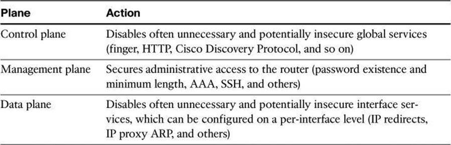
Table 3-4 lists some of the protection mechanisms that are activated when using Cisco AutoSecure. In general terms, Cisco AutoSecure protects the router functional planes by doing the following:
• Disabling often unnecessary and potentially insecure global services
• Enabling certain services that help further secure often necessary global services
• Disabling often unnecessary and potentially insecure interface services, which can be configured on a per-interface level
• Securing administrative access to the router
• Enabling appropriate security-related logging
Table 3-4. Cisco AutoSecure Protection for All Three Planes
Management Plane Security
Securing the network infrastructure requires securing the management access to the infrastructure devices. If infrastructure device access is compromised, the security and management of the entire network can be compromised. Consequently, it is critical to establish the appropriate controls to prevent unauthorized access to infrastructure devices.
Network infrastructure devices often provide a range of different access mechanisms, including console and asynchronous connections, as well as remote access based on protocols such as Telnet, rlogin, HTTP, and SSH. Some mechanisms are typically enabled by default with minimal security associated with them. For example, Cisco IOS Software–based platforms are shipped with console and modem access enabled by default. For this reason, each infrastructure device should be carefully reviewed and configured to ensure that only supported access mechanisms are enabled and that they are properly secured.
The recommended practices to secure both interactive and management access to an infrastructure device are as follows:
• Restrict device accessibility: Limit the accessible ports and restrict the permitted communicators and the permitted methods of access by enforcing a password policy.
• Present legal notification: Display legal notice developed with company legal counsel for interactive sessions.
• Authenticate access: Ensure that access is only granted to authenticated users, groups, and services. RBAC and authentication, authorization, and accounting (AAA) services provide mechanisms to effectively authenticate access.
• Authorize actions: Restrict the actions and views that are permitted by any particular user, group, or service. Actions can be restricted using ACLs and views can be limited using CLI views (discussed later in this book).
• Ensure the confidentiality of data: Protect sensitive data stored on management servers, such as syslog or SNMP servers, from viewing and copying. Consider the vulnerability of data in transit over a communication channel to sniffing, session hijacking, and man-in-the-middle attacks. Using management protocols with strong authentication, such as SNMPv3, mitigates confidentiality attacks that are aimed at exposing passwords, device configurations, and so on.
• Log and account for all access: Record who accessed the device, what occurred, and when for auditing purposes.
• Integrity of logs and digital certificate: Ensure the integrity of logs and digital certificate validation by synchronizing network time across all devices and network elements by using mechanisms such as Network Time Protocol (NTP). NTP helps the Security Information and Event Management (SIEM) server to perform more accurate correlation between multiple alarms that would have been received around the same time. NTP and its configuration will be covered in greater detail in Chapter 4, “Securing the Management Plane on Cisco IOS Devices and AAA.”
Secure Management and Reporting
Figure 3-4 shows a management module with two network segments that are separated by a Cisco IOS router that acts as a firewall and a VPN termination device. The segment outside of the firewall (the production network) connects to all of the devices that require management. The segment inside of the firewall contains the management hosts themselves and the Cisco IOS routers that act as terminal servers. Remote access, such as SSH, to network devices connected on the production network is either disabled or highly restricted.
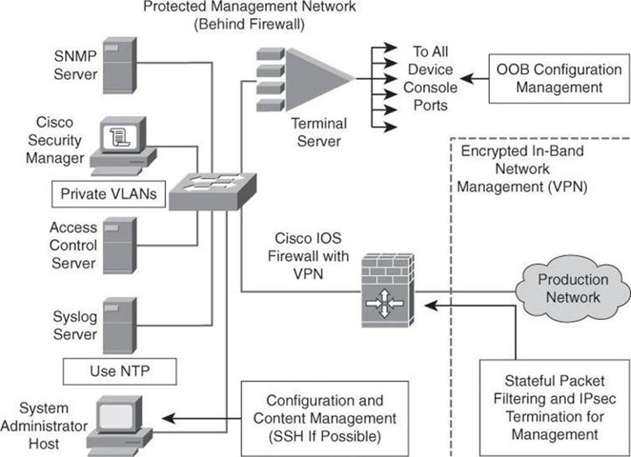
Figure 3-4. Example of Secure Management and Reporting
The information flow between management hosts and the managed devices can take two paths:
• Out-of-band (OOB): Information flows within a network on which no production traffic resides.
• In-band: Information flows across the enterprise production network, the Internet, or both.
The connection to the production network is only provided for selective Internet access, limited in-band management traffic, and IP Security (IPsec)-protected management traffic from predetermined hosts. In-band management occurs only when a management application does not function OOB, or when the Cisco device being managed does not physically have enough interfaces to support the normal management connection. This latter case employs IPsec tunnels. The Cisco IOS Firewall is configured to allow syslog information into the management segment and, in addition, Telnet, SSH, and SNMP, if these services are first initiated by the inside network. Stateful packet filtering and IPsec will be covered in detail later in this book.
Because the management network has administrative access to nearly every area of the network, it can be a very attractive target to hackers. The management module has been built with several technologies designed to mitigate such risks. The first primary threat is a hacker attempting to gain access to the management network itself. You can mitigate this threat only through the effective deployment of security features in the remaining modules in the enterprise. All of the remaining threats assume that the primary line of defense has been breached. To mitigate the threat of a compromised device, strong access control is implemented at the firewall, and at every other possible device, to prevent exploitation of the management channel. A compromised management device cannot even communicate with other hosts on the same management subnet because private VLANs (PVLAN) on the management segment switches force all traffic from the management devices directly to the Cisco IOS Firewall, where filtering takes place.
Network administrators need to securely manage all devices and hosts in the network. Management includes logging and reporting information flow, including content, configurations, and new software, from the devices to the management hosts.
From an architectural perspective, providing OOB management of network systems is the best first step in any management and reporting strategy. Devices should have a direct local connection to such a network where possible, and where this is not possible (because of geographic or system-related issues), the device should connect via a private encrypted tunnel over the production network. Such a tunnel should be preconfigured to permit only the traffic that is required for management and reporting. The tunnel should also be locked down so that only appropriate hosts can initiate and terminate tunnels.
It is important to note, however, that OOB management is not always desirable. Often, the decision depends on the type of management applications that you are running and the protocols that are required. For example, consider a management tool with the goal of determining the reachability of all the devices on the production network. If a critical link were to fail between two core switches, you would want this management console to alert an administrator.
If this management application is configured to use an OOB network, it may never determine that the link has failed, because the OOB network makes all devices appear to be attached to a single OOB management network. With management applications used to test reachability, it is therefore essential to run the management application in-band, as user traffic would do. In-band management needs to be configured in a secure manner.
SNMP management has its own set of security needs. Use SNMP version 3 (SNMPv3) where possible, because SMNPv3 supports authentication and encryption. Keeping SNMP traffic on the management segment allows the traffic to traverse an isolated segment when it pulls management information from devices. To reduce security risks, SNMP management should only pull information from devices and should not be allowed to push changes to the devices. To ensure that management information is pulled, each device is configured with a read-only SNMP community string. You can configure an SNMP read-write community string when using an OOB network. However, be aware of the increased security risk of a plaintext string that allows modification of device configurations if an older SNMP version is used. A rudimentary example of a read string would be “GET TEMPERATURE”, where the network management server inquires about the internal temperature of a router. An example of a more dangerous write string would be “SET RELOAD”, ordering a router to perform a reboot.
As mentioned earlier, it is important that all network devices be on the same time for proper log analysis. Time synchronization is best achieved by using NTP, which automates the process. The time distributed to the devices by NTP can be authenticated, through a process similar to routing authentication discussed earlier in this chapter. Authenticated time protects against spoofed NTP updates, which can corrupt logs and render digital certificates unusable.
Role-Based Access Control
RBAC is an access control approach that restricts user access based on the role of the user, along with their individual identity. Roles are created for job or task functions and assigned access permissions to specific assets. Users are then assigned to roles, through which assignment they acquire the permissions that are defined for the role. This means users are not assigned permissions directly, but only acquire them through role assignment, as shown in Figure 3-5. Managing the rights of an individual user becomes as simple as assigning appropriate roles to the user.
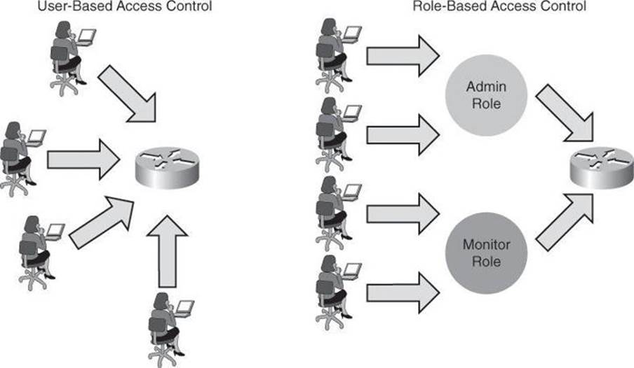
Figure 3-5. Advantage of Role-Based Access Control
With Cisco IOS, the role-based CLI access feature implements RBAC for router management access. This feature allows you to create different “views” of router configurations for different users. Views define which commands are accepted from different users and which configuration information is visible to them. With role-based CLI access, you can exercise better control over Cisco networking devices.
For scalability, users, permissions, and roles are usually created and maintained in a central repository, to make the access control policy available to multiple devices using it.
Deploying AAA
AAA servers are typically used as a central repository of authentication credentials (the users, answering the question “who is trying to access the device?”), authorization rules (the “what” users can accomplish), and accounting logs (the “what users did” part of the equation).
Figure 3-6 shows an example of the authentication and authorization process using an external AAA server such as Cisco Secure Access Control System (ACS) to provide AAA services to a network for management purposes.
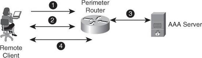
Figure 3-6. Authentication and Authorization Using an External AAA Server
In this chapter, we are concerned with limiting management access to our network equipment, and as such we will be discussing how to use AAA to limit the traffic to routers and switches for the purpose of owning the devices to manage them. In a later chapter, we will discuss the concept of using AAA to control traffic going through the devices.
In step 1, the client establishes a connection with the router.
In step 2, the router prompts the user for a username and password. The user sends her credentials to the router.
In step 3, the router passes the user’s credentials to the AAA server and advises the router that the user is authenticated.
In step 4, the user is authorized to access the router (administrative access) based on information found in the AAA server authorization database.
Data Plane Security
Among the laundry list of ways to protect the data plane, some that we will see in this book include
• Access control lists
• Private VLAN
• Firewalling
• Intrusion Prevention System (IPS)
Before discussing the details for data plane security, let’s review the most common means of protecting it, access control list (ACL) filtering, and then discuss briefly Layer 2 protection. Both of these topics are discussed in greater detail in subsequent chapters.
Access Control List Filtering
ACLs perform packet filtering to control which packets move through the network and where. Such control provides security by helping to limit network traffic, restrict the access of users and devices to the network, and prevent traffic from leaving a network. IP access lists can reduce the chance of spoofing and DoS attacks and allow dynamic, temporary user access through a firewall.
The following are the most common reasons to use ACLs:
• Block unwanted traffic or users: ACLs can filter incoming or outgoing packets on an interface, thus controlling access based on source addresses, destination addresses, or user authentication. You also can use ACLs to determine which types of traffic are forwarded or blocked at the router interfaces. For example, you can permit email traffic to be routed but at the same time block all Telnet traffic.
• Reduce the chance of DoS attacks for internal devices: There are a number of ways to reduce the chance of DoS attacks. For example, by specifying IP source addresses, you can control whether traffic from hosts, networks, or users accesses your network. You can filter on specific Time to Live (TTL) values in packets to control how many hops a packet can take before reaching a router in your network. By configuring the TCP Intercept feature, you can prevent servers from being flooded with requests for a connection.
• Mitigate spoofing attacks: ACLs allow security practitioners to implement recommended practices to mitigate spoofing attacks. The guidelines that are found in several RFCs provide basic filtering, and can be easily deployed using ACLs.
• Provide bandwidth control: An ACL on a slow link can prevent excess traffic
• Classify traffic to protect other planes: You can place an ACL on inbound vty (Telnet) line access from certain nodes or networks. For the control plane, ACLs can control routing updates being sent, received, or redistributed.
Antispoofing
One efficient use of ACLs is as an antispoofing mechanism. Spoofing protection involves discarding traffic that has an invalid source address. Network security baseline includes source IP spoofing protection that is based on BCP38/RFC 2827 ingress traffic filtering.
Packets with spoofed source IP addresses represent a security risk because they are often used to conduct an attack, to evade traceability and bypass access controls. These packets may also be used to direct an attack at a spoofed source, something that is known as a reflection attack, as shown in Figure 3-7. In this figure, the hacker sends packets with a source IP address of a third party. Hosts on network 171.1.0.0 reply to what they think to be the initiator of the echo-request and send the echo-replies to 200.1.1.1, which is not the originator of the ping.
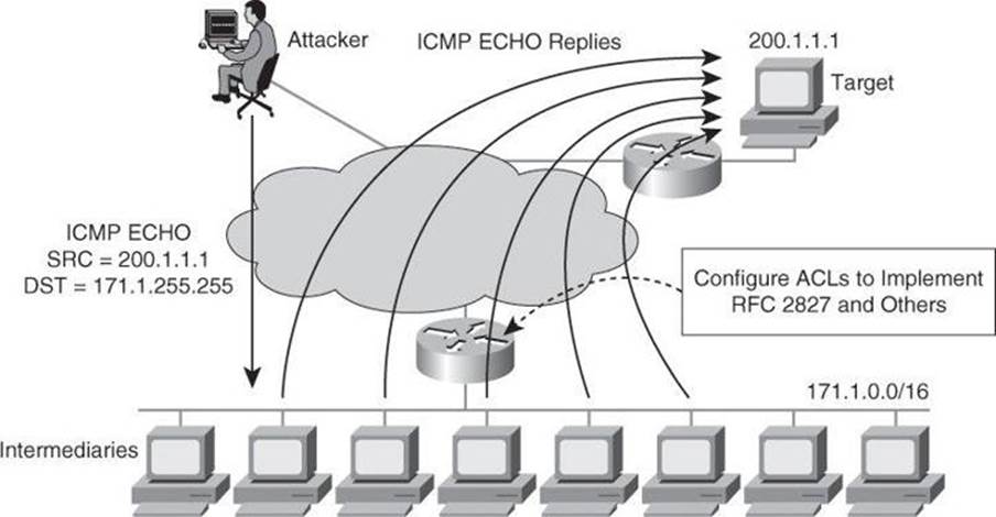
Figure 3-7. Attack Involving Spoofed Address
A variant of the attack shown in Figure 3-7 would be for the attacker to turn the 171.1.0.0 subnet workstations into members of a botnet, as explained in Chapter 1. The hacker could then order those zombies to launch TCP SYN packets to the victim, but spoofing as source IP address a third party. The victim would route its reply to the third-party address. This particular attack would create three casualties: the zombie site, which would have a high volume of outbound traffic; the destination victim; and the third site, whose address was invoked as the source IP address of the original request.
Spoofed traffic with an invalid source IP address may include traffic from either of the following:
• RFC 1918, Documented Special Use Addresses (DSUA), or unallocated IP address range
• Valid IP network address range, but not originating from the associated legitimate network
Implementing BCP38/RFC 2827 ingress traffic filtering to address source IP address spoofing renders the use of invalid source IP addresses ineffective, forcing attacks to be initiated from valid, reachable IP addresses. This implementation is beneficial because it enables greater success in tracing the originator of an attack.
ACLs are the traditional technique for filtering forged source IP addresses. However, ACLs are not dynamic in nature, requiring manual configuration changes, and may have an impact on the performance of a device. Other features, such as Unicast Reverse Path Forwarding (uRPF), can be used to complement the antispoofing strategy.
Note
Download document ID 13608, “Cisco Guide to Harden Cisco IOS Devices,” from Cisco.com for an informal discussion of some Cisco IOS system device configuration settings that network administrators could consider to harden their routers, especially perimeter routers.
Layer 2 Data Plane Protection
Data plane protection mechanisms depend on feature availability for specific devices. In a switching infrastructure, these Cisco Catalyst integrated security capabilities provide data plane security on the Cisco Catalyst switches using integrated tools:
• Port security prevents MAC flooding attacks.
• DHCP snooping prevents client attacks on the DHCP server and switch.
• Dynamic ARP Inspection (DAI) adds security to ARP by using the DHCP snooping table to minimize the impact of ARP poisoning and spoofing attacks.
• IP Source Guard prevents IP spoofing addresses by using the DHCP snooping table.
Some of the above controls will be discussed later in this book.
Now that we have seen in general terms the need for protecting the network infrastructure, let’s have a look at a GUI tool to help us harden our Cisco IOS routers.
Cisco Configuration Professional
CCP, shown in Figure 3-8, is a GUI-based device management tool for Cisco access routers, specifically Integrated Services Routers (ISR) and Integrated Services Routers Generation 2 (ISR G2). This tool simplifies routing, firewall, IPS, VPN, unified communications, WAN, and LAN configuration through GUI-based wizards.
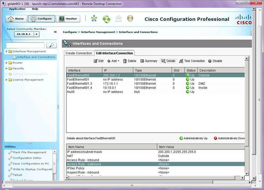
Figure 3-8. CCP GUI
CCP is a valuable productivity-enhancing tool for network administrators, used for deploying routers with increased confidence and ease. It offers a one-click router lockdown and an innovative voice and security auditing capability to check and recommend changes to router configuration. CCP also monitors router status and troubleshoots WAN and VPN connectivity issues. The GUI includes options to configure Cisco Services-Ready Engine (SRE) modules, facilitating the integration of hardware-based functionality and centralizing their configuration in the same place where the hosting router is configured.
CCP is free, and you can download it from http://www.cisco.com/go/ciscocp. CCP can be preinstalled in the flash memory of the router, typically in its express version.
The following list summarizes the benefits of using CCP:
• Supports configuration of advanced technology deployment on ISRs and ISR - G2 through a single integrated tool
• Simplifies routing, firewall, IPS, VPN, unified communications, WAN, and LAN configuration through GUI-based easy-to-use wizards
• Monitors router status and troubleshoots WAN and VPN connectivity issues
• Provides smart wizards for routing and security configuration
• Offers license management for ISR-G2
The following are features of CCP Express:
• A lightweight version of CCP
• Router flash
• LAN and WAN interfaces
By relying on best-practice configurations that are approved by the Cisco Technical Assistance Center (TAC), network administrators can take advantage of CCP, which does the following:
• Lowers the total cost of ownership (TCO) of Cisco routers
• Reduces human errors
• Simplifies initial setup in voice deployments
• Helps ensure proper linkage between users, dialing plans, and voicemail settings
CCP offers smart wizards and advanced configuration support for the following:
• LAN and WAN interfaces
• Network Address Translation (NAT)
• Stateful and application firewall policy
• IPS, IPsec, and SSL VPNs
• Quality of service (QoS)
• Cisco Network Admission Control (NAC) policy features
CCP enables IT managers to easily organize and manage multiple routers at a single site.
CCP Initial Configuration
Devices that are shipped with CCP have a default configuration that allows you to connect a PC to an Ethernet port on the device and start configuration immediately. This initial configuration is accomplished using CCP Express. CCP Express and a factory default configuration file are installed in flash memory on routers that are shipped with CCP. You can connect a PC directly to the device, and then use CCP Express to configure LAN and WAN connections, a firewall, and NAT and make security settings before you place the device on the network in which it will operate. After you have configured the device and connected it to the network, you will be able to use CCP to connect to the device over the network and make advanced configurations.
Figure 3-9 provides a visual aid to the following configuration procedure:
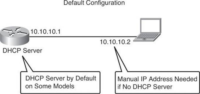
Figure 3-9. Connecting to the Default CCP Settings of an ISR
Step 1. The device default configuration file configures an IP address for one Ethernet interface, and that may configure the device as a DHCP server. See Table 3-5 to determine whether the device is configured as a DHCP server, and which Ethernet port to connect the PC to.
Table 3-5. Cisco Configuration Professional—Defaults According to Models
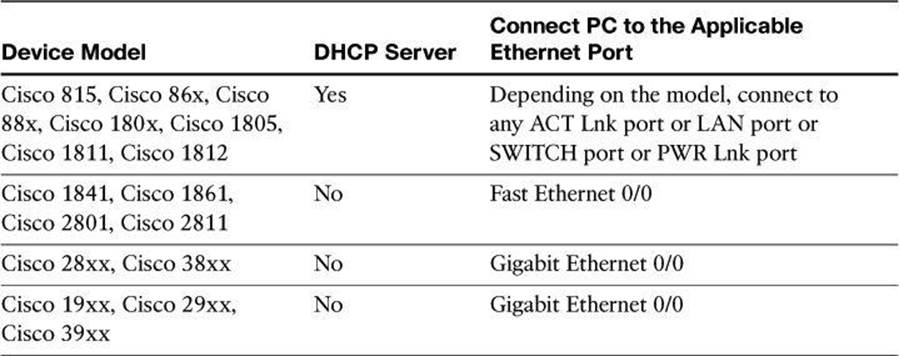
Refer to CCP and ISR documentation on Cisco.com for an up-to-date list of defaults and detailed information on applicable Ethernet ports depending on model.
Step 2. Connect the PC to the appropriate port listed in Table 3-5.
Step 3. Configure the PC IP address by doing one of the following:
• If the device is configured as a DHCP server, ensure that the PC is configured to accept an IP address from a DHCP server.
• If the device is not configured as a DHCP server, configure the static IP address 10.10.10.2 on the PC, and use the subnet mask 255.255.255.248.
Step 4. Open an Internet Explorer browser window, and enter the IP address 10.10.10.1 to connect to the device and start CCP Express.
Step 5. Complete the CCP Express wizard to configure the device.
When you have completed initial setup and given the device an IP address on your LAN, you can use CCP to connect to the device and perform additional configuration.
To use CCP with an already deployed device, enter the commands shown in Table 3-6.
Table 3-6. Command to Provision a Deployed Device with CCP Support
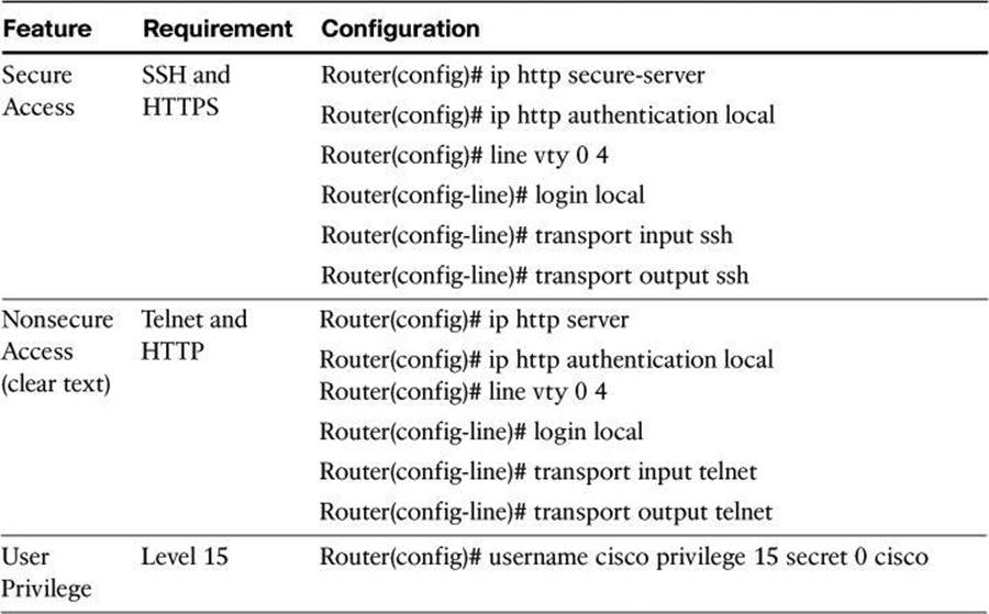
Note
In the username command of Table 3-6, the 0 indicates that the following password is clear text, which should be avoided. If the value would have been set to 5, it would have indicated that the following password would appear encrypted in configuration files.
Also, connecting CCP to a new device for the first time can be accomplished by choosing Application > Setup New Device in CCP, which you have manually installed on your PC. Connect your local PC to the console port of the router. This approach, shown in Figure 3-10, sounds counterintuitive—using a GUI through a serial port—but works, where CCP uses the console connection of your local PC to attempt to reach the router to configure it. For this to work, ensure that no other terminal monitor application is currently accessing the console port of the router.
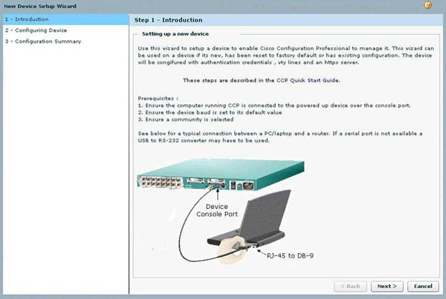
Figure 3-10. CCP Used to Discover a Device Using the Serial Connection of a PC
Cisco Configuration Professional User Interface and Features
Although every aspect of CCP is important and useful, due to space constraints, we will focus in the following pages only on the most relevant options and features of CCP.
Note
If you would like to follow along with these explanations of CCP, you can download the Cisco Configuration Professional Demo version from Cisco.com, using your Cisco.com user ID. This simulator is prefilled with routers and configurations so you can practice your CCP navigational and configuration skills without interfering with equipment currently in production. However, some features are not available or configurable in Demo or Offline modes.
CCP eliminates the need for multiple device managers by providing a single tool to configure and manage devices. The user interface makes it easy to manage networking features. The main parts that define the user interface are shown in Figure 3-11 and include the following:
• Menu bar: The row of menus across the top of the window. The menu bar offers application services, a list of open windows, and online help.
• Toolbar: The row of icons directly below the menu bar. These icons represent the most often used application services and most often configured networking features.
• Left navigation pane: This navigation pane is the scalable panel on the left side of the content pane in which you select the features to configure and monitor.
• Content pane: This pane is the right side of the workspace in which windows appear. You view reports here and enter information that configures networking features.
• Status bar: The status bar is the bar at the bottom of the window where CCP displays the status of the application. A closed lock icon refers to a secure connection and an opened lock icon refers to an unsecure connection.
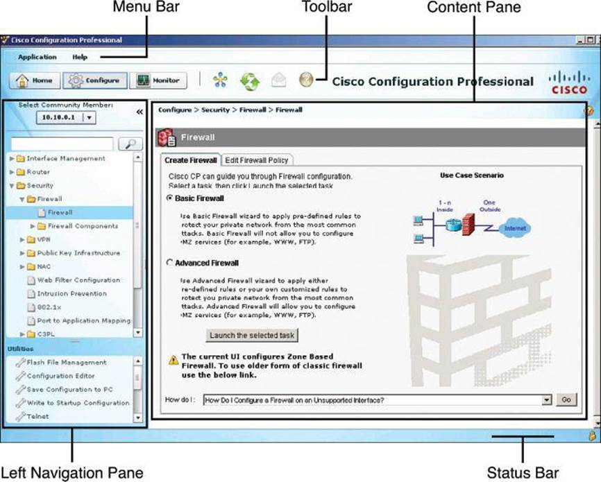
Figure 3-11. Navigating the GUI of Cisco Configuration Professional
Menu Bar
The row of menus across the top of the window offer application services and help. Figure 3-12 identifies the options in the Application menu, which are described here:
• Manage Community: Enables you to create a new community or choose an existing community. A community member would be a router that you manage with CCP.
• Setup New Device: Enables you to set up a new device.
• Create User Profile: Enables you to restrict users from using all of the features that are available in the left navigation pane.
• Import User Profile: Enables you to import a user profile.
• Options: Enables you to set user preferences such as log level, show community at startup, and show CLI preview parameters.
• Template: Enables you to create, edit, or apply a template.
• Work Offline: Enables you to work with CCP in offline mode.
• Exit: Exits the CCP application.
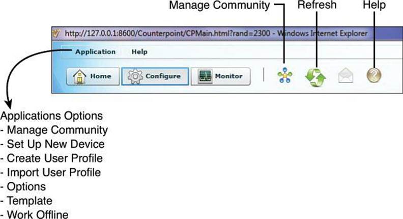
Figure 3-12. CCP Toolbar
Toolbar
The following CCP features are available from the toolbar at the top of the window, as shown in Figure 3-12:
• Home: Click Home to display the Community View page, which summarizes the community information and allows you to add, edit, and discover devices and view the discovery and router status of each device.
• Configure: Click Configure to display the features that you can configure on a chosen device. The features are displayed in the left navigation pane, as shown in Figure 3-12. Note that if a feature (router, security, or voice) is not supported on a device, that feature is not displayed in the left navigation pane. However, if the Cisco IOS version that is installed on the device does not support a specific feature, but an upgrade does support it, then that feature is disabled (grayed out) in the left navigation pane.
• Monitor: Click Monitor to display the router and security features that you can monitor for a chosen device. The features are displayed in the left navigation pane.
• Manage Community: Click this icon to open the Manage Community dialog box, where you can add a new community or edit an existing community.
• Refresh: Click this icon to do the following:
• Rediscover the selected device in the Select Community Member drop-down menu
• Rediscover and reload the current feature
Note that the Refresh function is not available for offline mode, and is available in online mode only after successful discovery of one or more devices. Clicking Refresh refreshes the device that is selected in the Select Community Member drop-down menu. Choosing Home > Dashboard, selecting a device, and clicking Refresh does not refresh that device.
Navigation Pane
The following options are found in the navigation pane on the left of the screen, as shown in Figure 3-11.
Interface Management
The CCP connection wizards guide you through LAN and WAN configurations, and check the information that you enter against the existing configuration, warning you of any problems. The supported interfaces are
• LAN
• WAN
• Wireless LAN
• Cellular WAN (3G)
• Analog trunks
• Digital trunks
In addition, CCP can be used to configure EnergyWise features for power management.
The Interface Management folder on the navigation pane provides configuration support for interfaces and service modules. CCP can configure the modules management, install applications, and upgrade images. The following service modules are supported:
• Network modules
• Enhanced network modules
• Cisco Wide Area Application Services (WAAS) modules
• Advanced Integration Modules (AIM)
• Voice Network Modules (VNM)
• Services-Ready Engine (SRE) modules
Support for Services-Ready Engine Virtualization (SRE-V) allows you to do the following:
• Install SRE-V software on SM-SRE 700 and 900 modules
• Edit console manager and hypervisor IP configurations
• Launch the vSphere client user interface from CCP
• Configure users, groups, roles and permissions, and syslog
• View license details
Note
Cisco SRE-V is a branch-office infrastructure platform that combines computing, networking, storage, virtualization, and unified management into a cohesive system. It enables the VMware vSphere Hypervisor to be provisioned on a Cisco Services-Ready Engine (SRE) Service Module and host one or more virtual machines running Microsoft Windows Server operating system. The entire system is integrated with Generation 2 of the Cisco Integrated Services Router (ISR-G2). Further information can be found at Cisco.com.
Router
The Router folder, in the left navigation pane, displays the routing window with the configured static routes and Routing Internet Protocol (RIP), Open Shortest Path First (OSPF), and Extended Interior Gateway Routing Protocol (EIGRP) configured routes. From this window, you can review routes, add new routes, edit existing routes, and delete routes.
Under the Router folder, the administration can also set the hostname, username, and password. Other supported routing functions include NAT, DHCP, Domain Name System (DNS), QoS, and Cisco Performance Routing (PfR).
The Router folder is also used for overall management options, related to AAA, management access, logging, and others.
Security
CCP can be used to manage functions that comprise a large portion of the topics discussed in this book. They include
• Device hardening via the One-Step Lockdown and Security Audit wizards
• VPN options for IPsec and SSL site-to-site and remote access deployments
• Zone-based firewall wizards, as well as classic Cisco IOS firewall configuration options for backwards compatibility
• Cisco IOS IPS wizards
Each is discussed in turn next.
Device Hardening Security Audit is a feature that examines your existing router configurations and then updates your router in order to make your router and network more secure. Security Audit is based on the Cisco AutoSecure feature. It performs checks on and assists in configuration of almost all of the AutoSecure functions.
Security Audit operates in one of two modes. The first mode is the Security Audit wizard, which lets you choose which potential security-related configuration changes to implement on your router. The second mode is One-Step Lockdown, which automatically makes all recommended security-related configuration changes.
VPN Comprehensive VPN configuration can be accomplished using CCP options. A wizard-like VPN Design Guide is available, helping you to determine which kind of VPN to configure, among site-to-site, remote access (SSL and IPsec using Easy VPN and Virtual Tunnel Interface [VTI]), Dynamic Multipoint VPN (DMVPN), and Group Encrypted Transport (GET) VPN. The input parameters include information about what type of user you are, the type of equipment that the router establishes VPN connections with, the type of traffic that the VPN will carry, and other features that you need to configure. After you provide this information, the VPN Design Guide recommends a VPN type and allows you to launch the wizard that will enable you to configure that type of VPN.
For ease of configuration, CCP offers a VPN option to create a text file that captures the VPN configuration of the local router. This file can be used to configure a remote router that enables it to establish a VPN connection to the local router.
Firewall The firewall option simplifies access control configuration using smart wizards. Two firewall wizards are available:
• Basic Firewall: Creates a firewall using default rules. The use case scenario shows a typical network configuration in which this kind of firewall is used.
• Advanced Firewall: Leads you through the steps of configuring a firewall. You can create a demilitarized zone (DMZ) network and specify an inspection rule. The use case scenario that is shown when you choose this option shows you a typical configuration for an Internet firewall.
CCP provides preconfigured application security policies that you can use to protect the network. Using a simple slider bar, you can select the security level that you want and view a description of the security it provides. The wizard summary screen displays the policy name and the configuration statements in the policy.
Comprehensive editing tools are available to maintain the firewall ruleset, with quick edit options and a graphical view of the ruleset that allows you to understand the scope of the rule and the zones and interfaces involved.
You can also view the details of the policy by clicking the Application Security tab and choosing the name of the policy. Application inspection rules for deep packet inspection are available.
IPS The IPS option simplifies intrusion management using a wizard-based approach to configuration. CCP allows for a simplified initialization, update, and management of IPS signatures, including intuitive options for signature tuning in order to improve the accuracy and sensitivity of the system. This allows for improved chances of managing false positives and false negatives.
The IPS option also includes a Security Dashboard, which displays threat information in the form of top threats table, and allows the administrator to visualize the events and incidents generated by the IOS IPS functionality.
Management, Monitoring, and Troubleshooting Comprehensive monitoring and troubleshooting options are available by clicking the Monitor button in the toolbar shown in Figure 3-12. Convenient tools allow detailed troubleshooting, including connectivity testing tools that generate real traffic and provide visual cues as to potential configuration or connectivity issues.
Content Pane
The content pane, located on the right side of the workspace, is where the configuration takes place. The content pane changes depending on the selection you make on the navigation pane, located on the left of the window. In addition to configuring networking features from the content pane, you can view and monitor the equipment.
Status Bar
The status bar appears at the bottom of the window and displays the current communication status with the device. A locked padlock icon indicates that CCP has a secure connection with the chosen community member. The unlocked padlock icon indicates that CCP has a nonsecure connection with the chosen community member.
Cisco Configuration Professional Building Blocks
When using Cisco Configuration Professional, you can take advantage of the following tools to facilitate and direct the process. These building blocks simplify operations, allow RBAC, and provide bulk configuration and monitoring options for multiple devices.
• Communities: Groups of devices that share common components. Communities can be used to group devices based on geographic location, device function, and so on.
• Templates: Parameterized configuration files that can be created once with a common configuration and applied multiple times by using configuration variables that change value for each device.
• User profiles: GUI views that allow RBAC over CCP menus and options.
RBAC is discussed further in Chapter 4.
Communities
A community is basically a group of devices (known as community members). A single community can contain a maximum of ten devices. You can create a community and then add devices to it based on some common parameters. For example, you can create communities that are based on the location of the devices. You can create a San Jose community and add devices to it, and then you can create a Bangalore community and add devices to it, and so on.
Before you begin using CCP, you must first create a community and then add devices to that community. When you start CCP for the first time, CCP automatically creates a community for you, to which you can add devices. Devices are discovered on the network, and their configuration is uploaded to CCP.
When you add a device to a community, you must specify its IP address or hostname, credential information (username and password), and whether the communication will be secured. CCP uses this information to discover the device. After you discover the device, you can configure and monitor it. Again, up to ten devices can be added to each community.
You can create and manage communities from the Manage Community dialog box.
Creating Communities
The following list shows how to create and manage communities in CCP:
Step 1. Use the Manage Community dialog box to create communities. The Manage Community dialog box automatically displays when you start Cisco Configuration Professional, with a community called New Community created by default.
You can also open the Manage Community dialog box in the following ways, shown in Figure 3-13:
• From the toolbar, click the Manage Community icon.
• From the menu bar, choose Application > Manage Community.
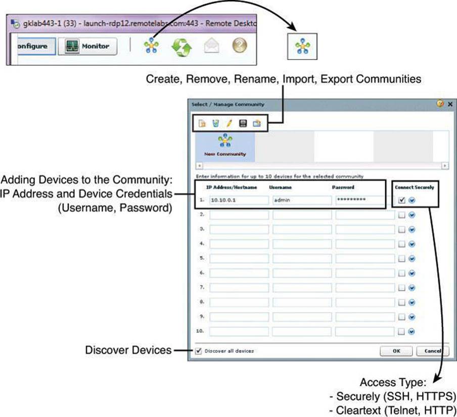
Figure 3-13. Creating Communities from the Application Menu or with the Icon on the Toolbar
Step 2. In the Manage Community dialog box, enter the IP address or hostname and the username and password information for the devices that you want to configure. If you enter the default username cisco and default password cisco, the Change Default Credentials dialog box opens. For security reasons, you must change the default credentials to new credentials.
Step 3. If you want CCP to connect securely with the device, check Connect Securely. To view the port information, click the down arrow next to the Connect Securely check box.
Step 4. If you want to change the default port information, click it, and then enter a new port value.
Make sure that CCP can access the device at the specified secure or nonsecure ports.
Step 5. If you want CCP to discover all the devices in a community, check Discover All Devices. If you want, you can choose to discover the devices later, from the Community View page.
Step 6. Click OK. The Community View page opens. It displays the information about the devices in the community.
Managing Communities
After you create a community and add devices to it, you can view the information for that community by clicking the only available selection in the navigation pane, a page called Community View. Clicking Community View refreshes the information appearing in the Community Information pane. From the Community Information pane, you can manage the devices (community members) in a community, such as add devices to a selected community, edit device information, delete devices, discover the devices, view information about the discovery process, and view hardware and software information about a selected device.
Figure 3-14 illustrates the Community View option in CCP. The list of devices appears in the content pane, and the selected device can be quickly chosen using the Select Community Member drop-down menu. The buttons at the bottom of the window include the Discover button, which enables you to discover or rediscover devices, the Discovery Details button, which displays a log of events and errors that may arise during the discovery process, the Manage Devices button, which enables you to manage device IP addresses and credentials, and the Router Status button, which displays the status of the devices.
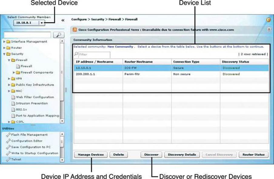
Figure 3-14. Managing Devices Within the Community
Templates
Templates facilitate management and consistency by attributing parameters to common components of configuration files (known as parameterizing). Using the template options, you can convert specific components of the configuration files into variables, which will acquire a different value for different devices that use the template.
After the template is created, it can be applied to multiple devices in different communities. The process includes options to provide values to the variables on the template, making them specific to each device. The template remains untouched. When applying the template, you can override the existing configuration, or merge the resulting configuration into the existing configuration.
Figure 3-15 illustrates the template management options. The wizard-based process guides you through the following steps to create a template:
Step 1. Choose Application > Template > Create.
Step 2. Select the device from which you will obtain the template or select a configuration file from the local PC.
Step 3. Check the Include This Configuration in the Template check box.
Step 4. Find and select the attribute to be converted to variables, and click the Parameterize.
You can click Unparameterize to undo the action if the attribute is not to become a variable. The selected attribute is wrapped within a double set of curly brackets {{}}. For instance, the word demoone becomes {{demoone}} after being parameterized.
Step 5. Click Finish and select the template filename and location.
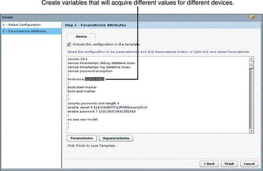
Figure 3-15. Creating Variables in CCP Templates
After the template is created, you can apply it to multiple devices by following these steps:
Step 1. Choose Application > Template > Apply.
Step 2. Click the browse button and navigate to select the template file.
Step 3. Click Find Parameterized Attribute to find and select specific text, and then change the value of the text to the value specific for the device.
Step 4. In the Apply to Device step, shown in Figure 3-16, choose the router to apply the template from the Select Device drop-down list, and then click the respective radio button to select whether to merge with or override the running configuration. Check the Enable Rollbackcheck box if rollback is desired.
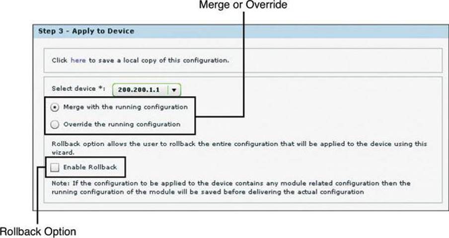
Figure 3-16. Applying a Template on a Discovered Device
Step 5. Click the Reload Device button to apply overridden configurations, or click Rollback to return to the previous configuration and discard the changes.
User Profiles
User profiles are a tool to define configuration views on CCP. Using profiles, administrators can define the view and configure which menus and screens are visible to the users who are acquiring the profile. This process effectively creates a different CCP option tree, where screens are available to profile users in full permission mode or in read-only mode.
Figure 3-17 illustrates the profile management options. The wizard-based process guides you through the following steps to create a profile:
Step 1. Choose Application > Create User Profile.
Step 2. Click to select the device or devices that will be part of the user profile.
Step 3. The resulting folders represent the CCP option tree. Expand the folders to find the menus and screens.
Step 4. Select screens to set permissions.
Step 5. Check the check boxes to define permissions. The following permissions are available:
• Show this screen: Makes the screen visible to users acquiring the profile, and defines full permission over the components of the screen.
• Restrict to read operations only: Changes the screen permissions to view-only or read-only.
• Disabled: This option does not appear explicitly, but can be accomplished by clearing the two check boxes for the previously listed permissions.
Step 6. Click Save to save the user profile as a file.
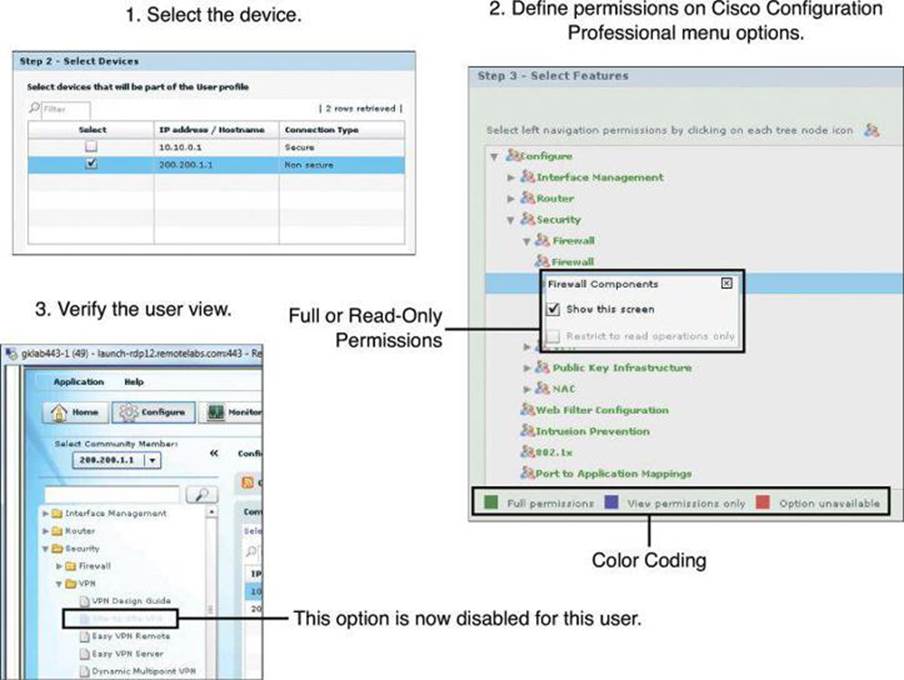
Figure 3-17. Using User Profiles
Following this configuration, users will see options that are grayed out when they try to access screens that have been disabled for access, and they will see buttons and check boxes that are grayed out when they try to use options on screens that have been designated as read-only.
Using CCP to Harden Cisco IOS Devices
There are two options to harden your Cisco IOS devices, as shown in Figure 3-18: the Security Audit or the One-Step Lockdown. The Security Audit approach is more granular than the One-Step Lockdown options. With the One-Step Lockdown approach, CCP evaluates and hardens your device without the option for you to review the changes about to be made.
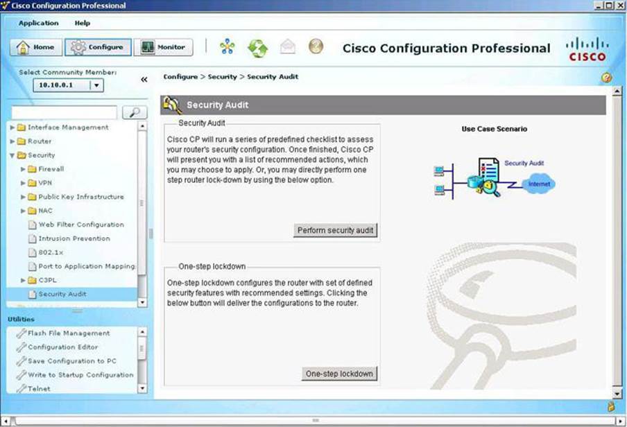
Figure 3-18. Security Audit Tools
Security Audit
The Security Audit Wizard implements device hardening by testing your router configuration to determine if any potential security problems exist in the configuration. The wizard then presents you with a screen that lets you determine which security problems you want to fix. Once determined, the Security Audit Wizard makes the necessary changes to the router configuration to fix those problems using One-Step Lockdown.
Following are the steps to perform the security audit:
Step 1. From the toolbar, choose Configure > Security > Security Audit.
Step 2. Click Perform Security Audit. The Welcome page of the Security Audit Wizard opens.
Step 3. Click Next. The Security Audit Interface Configuration page opens.
Step 4. Input information to tell the Security Audit Wizard which of your router interfaces connect to your inside network and which connect outside of your network. For each interface listed, check either Inside or Outside to indicate where the interface connects, as shown inFigure 3-19.
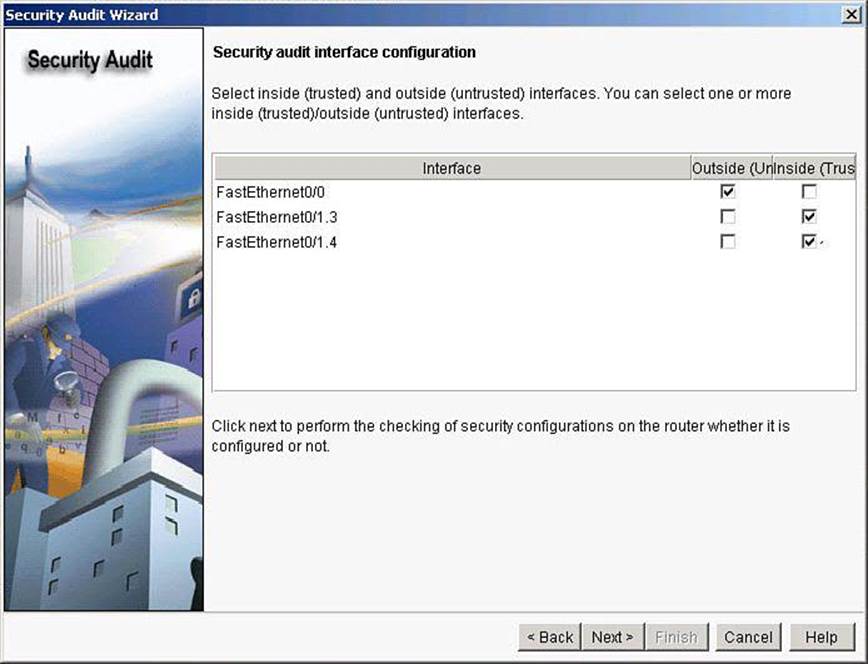
Figure 3-19. Selecting Interfaces for a Successful Security Audit
Step 5. Click Next. The Security Audit Wizard tests your router configuration to determine if possible security problems exist. The potential problems are determined by Cisco recommended practices. A screen showing the progress of this action opens, listing all of the configuration options being tested for, and whether the current router configuration passes those tests, as shown in Figure 3-20. If you want to save this report to a file, click Save Report.
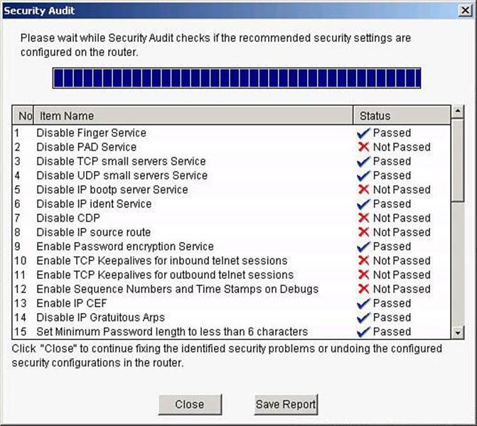
Figure 3-20. Security Audit Results
Step 6. Click Close. The Security Audit Wizard displays a “report card” showing a list of possible security problems, as shown in Figure 3-21.
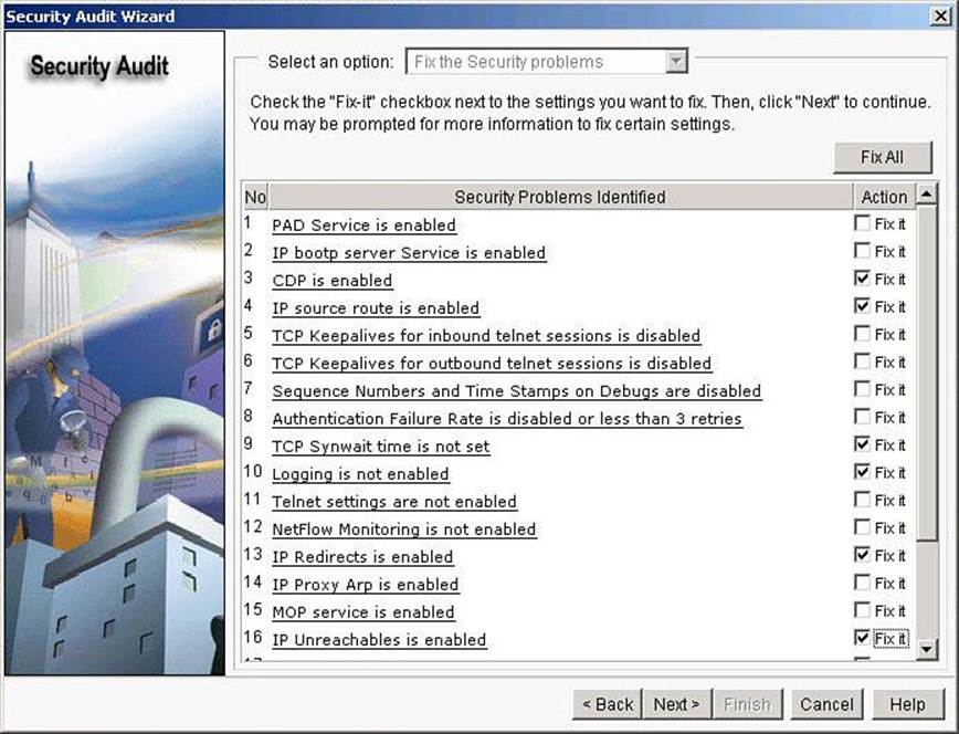
Figure 3-21. Addressing Issues Reported by the CCP Security Audit
Step 7. Check the Fix It check box next to any problems that you want CCP to fix. For a description of the problem and a list of the Cisco IOS commands that will be added to your configuration, click the problem description to display a help page about that problem.
Step 8. Click Next. The Security Audit Wizard may display one or more screens requiring you to enter information to fix certain problems. Enter the information as required and click Next for each of those screens.
Step 9. The Summary page of the wizard shows a list of all the configuration changes that Security Audit will make. Click Finish to implement those changes to your router.
CCP can undo this security fix. If you want CCP to remove this security configuration, run the Security Audit Wizard. In the report card window shown in Figure 3-21, choose the option Undo Security Configurations from the drop-down list at the top of the window, and check the check box next to any configurations that you want to undo. Click Next.
One-Step Lockdown
The One-Step Lockdown option, available from the Security Audit main menu shown in Figure 3-18, tests your router configuration for potential security problems and automatically makes necessary configuration changes to correct problems that are found. The configuration is evaluated against Cisco recommended practices, similar to the Security Audit Wizard. This time, however, changes are made automatically and without prompting the user to select components to fix. Choose Configure > Security > Security Audit > One-Step Lockdown.
The One-Step Lockdown option streamlines device hardening by implementing the AutoSecure feature with a one-click option. To confirm the process, click the Deliver button in the confirmation dialog box, shown in Figure 3-22, to deliver the new settings. Notice that the confirmation dialog box also explains how to roll back the new settings using the Security Audit feature. Also, notice that the wizard lists the settings as changed before offering the option to deliver them.
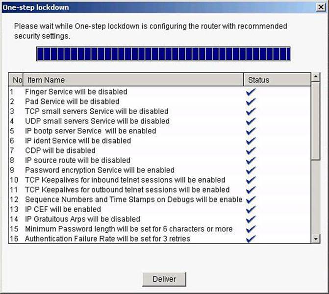
Figure 3-22. One-Step Lockdown
Cisco IOS AutoSecure
The following list provides examples of the Cisco AutoSecure features that are implemented in CCP during the One-Step Lockdown (refer to the CCP documentation on Cisco.com for an updated list of features):
• Disable unnecessary services and interfaces
• Unused router interfaces
• BOOTP server
• Cisco Discovery Protocol
• Configuration autoloading
• FTP server
• TFTP server
• NTP service
• PAD service
• TCP and UDP minor services
• DEC MOP service
• Disable commonly configured management services
• SNMP
• HTTP or HTTPS configuration and monitoring
• DNS
• Ensure path integrity
• Disable ICMP redirects
• Disable IP source routing
• Disable IP directed broadcast
• Disable gratuitous and proxy ARP
• Enable firewall on all outside interfaces
• Disable probes and scans
• Finger
• ICMP unreachable notifications
• ICMP mask reply
• Ensure terminal access security
• Enable SSH
• Disable IP identification service
• Enable TCP keepalives
• Set access class on HTTP and vty
• Ensure authentication integrity
• Enable password encryption
• Set minimum password length
• Set authentication failure rate
AutoSecure is a Cisco IOS feature that, like CCP, lets you more easily configure security features on your router, so that your network is better protected. CCP implements almost all of the configurations that AutoSecure provides.
The following AutoSecure features might not be implemented in CCP:
• Disabling Network Time Protocol (NTP): Based on input, AutoSecure will disable NTP if it is not necessary. Otherwise, NTP will be configured with Message Digest 5 (MD5) authentication. CCP does not support disabling NTP.
• Configuring AAA: If AAA is not configured, AutoSecure configures local AAA and prompts for configuration of a local username and password database on the router. CCP does not support AAA configuration.
• Setting Selective Packet Discard (SPD) values: CCP does not set SPD values.
• Enabling TCP Intercept feature: CCP does not enable TCP Intercept feature.
• Configuring antispoofing ACLs on outside interfaces: AutoSecure creates three named ACLs used to prevent antispoofing source addresses. CCP does not configure these ACLs.
CCP implements the following Cisco AutoSecure features differently:
• Disable Simple Network Management Protocol (SNMP): CCP will disable SNMP, but unlike AutoSecure, it does not provide an option for configuring SNMP version 3.
• Enable SSH for access to the router: CCP will enable and configure SSH on crypto Cisco IOS images, but unlike AutoSecure, it will not enable Service Control Point (SCP) or disable other access and file transfer services, such as FTP.
For the details on what is included with CCP, and its detailed functioning (such as whether admin rights are required), read the release notes for the specific version you are working with.
Summary
This chapter had two distinct parts. In the first part, we explored Cisco Network Foundation Protection and discussed, among other things:
• Threats that exploit network availability drive infrastructure protection.
• Cisco Network Foundation Protection implements a divide-and-conquer approach to infrastructure protection.
• Control plane security tools include CoPP and Cisco AutoSecure.
• Management plane security tools include RBAC and AAA services.
• Data plane security tools include ACLs, DHCP snooping, and Dynamic ARP spoofing.
In the second part of this chapter, we saw how Cisco Configuration Professional can be used to implement Cisco Network Foundation Protection, and how CCP provides a comprehensive and easy-to-use GUI tool for router configuration and service integration. Among other things, you learned:
• Features include security, unified communication, license management, application management, and others.
• Communities, templates, and user profiles provide role-based access control and streamline the process of configuring several devices.
• The Security Audit Wizard and the One-Step Lockdown tool are device hardening options.
References
For additional information, refer to these Cisco.com resources:
Cisco Configuration Professional User Guide (Version 2.5), http://www.cisco.com/en/US/docs/net_mgmt/cisco_configuration_professional/v2_5/olh/ccp.pdf
“Cisco Network Foundation Protection (NFP),” http://www.cisco.com/en/US/products/ps6642/index.html
Review Questions
Use the questions here to review what you learned in this chapter. The correct answers are found in the Appendix, “Answers to Chapter Review Questions.”
1. Which device plane processes traffic generated or received by the network device itself, used for the creation and operation of the network, and managed by the CPU in the device route processor?
a. Control plane
b. Data plane
c. Forwarding plane
d. Management plane
2. What is the main difference between Control Plane Policing (CoPP) and Control Plane Protection (CPPr)?
a. No difference exists; both terms define the same functionality.
b. CoPP is an extension of CPPr.
c. CPPr is an extension of CoPP.
d. CoPP relates to rate limiting, while CPPr defines QoS-like filters.
e. CoPP allows more granularity on CPPr rules.
3. Which of the following are components of Control Plane Protection? (Choose two.)
a. Routing protocol authentication
b. SNMP
c. Cisco SecureX
d. Cisco AutoSecure
e. Zone-based firewall
4. Which options are examples of data plane security controls? (Choose two.)
a. RBAC
b. CoPP
c. Port security
d. Spanning Tree Control
e. Access control lists
f. AAA
5. Match the plane with the right traffic type.
Planes
a. Management
b. Data
c. Control
Traffic
d. User-generated packets
e. Packets used for the creation and operation of the network itself
f. Packets used to manage the network
6. Which techniques could be used to mitigate a spoofing attack? (Choose two.)
a. TTL filtering
b. Access class
c. Private VLANs
d. Access list
e. Management plane
f. Unicast Reverse Path Forwarding
7. Which management tool is available on the router’s flash and can be used to configure some LAN and WAN interfaces of the router, as well as minimal Cisco IOS Software security features?
a. Cisco AnyConnect
b. Cisco Configuration Professional Express
c. Cisco Secure Desktop
d. CiscoWorks
e. Cisco Security Manager
f. Cisco Configuration Professional
8. Match the Cisco Configuration Professional component with its definition.
CCP components
a. Communities
b. Templates
c. Profiles
d. Wizards
Component definitions
e. Parameterized configuration files
f. GUI views that allow role-based access control over Cisco Configuration Professional menus and options
g. Groups of devices that share common components
h. GUI tools to hide the complexity of commands
9. What does the Parameterize button do when creating Cisco Configuration Professional templates?
a. Creates variables that acquire different values for different devices
b. Designates a parameter for use across several communities
c. Applies the same parameter to the configurations of all devices where the parameter is applied
d. Removes the special value of a given parameter
10. Which of the following is implemented by Cisco Configuration Professional when the One-Step Lockdown option is used?
a. Control Plane Protection
b. Security Wizard
c. AutoSecure
d. Packet Tracer