Praise for Hacking Exposed: Unified communications & VoIP Security Secrets & Solutions, Second Edition (2014)
PART IV. UC SESSION AND APPLICATION HACKING
CHAPTER 16. AUDIO AND VIDEO MANIPULATION
Wow, my father is upset with me; I don’t think he will forgive me. Last week he put me in charge of his 401k, and I set up a video call with his broker in an attempt to consolidate his accounts in preparation for retirement. Before I took over, his account had well over $250,000. This week he received a letter from his broker summarizing that he cashed out his entire account and that a check was forthcoming in the next few days. What happened? Why did the broker sell his lot? We now have to deal with the taxman, who is expecting a cut of the proceeds.
—A frustrated user who is the target of a video attack
In previous chapters, we covered attacks where an attacker exploits SIP signaling to hijack or otherwise manipulate calls. In this chapter, we dive into attacks perpetrated via the media plane, spanning audio and video. The first series of attacks we discuss relate to media hijacking and injection attacks. These attacks can be used to add or remove media from active communication streams between parties. A number of scenarios exist where these types of attacks cause real harm. The next series of attacks we discuss relate to the broad topic of steganography—audio and video used for the purposes of data exfiltration or even offensive capabilities such as data infiltration. In either case, the media channel is now the nuclear-tipped Tomahawk cruise missile through which theft of proprietary data or denial of service is delivered to your enterprise.
The aforementioned attacks rely on exploit methods observed in the data world. What raises the profile of these attacks in the UC world is the fact that media streams are typically accorded a lower level of protection and end users are highly sensitive to service perturbations. When was the last time you had a fit when your email was delayed by a few seconds? You probably didn’t even know it was happening. In the UC world, however, even small service abnormalities are apparent to end users due to the real-time nature of the media plane.
We discussed RTP in Chapter 4 and will plunge into the semantics in this chapter, but for now a general description will suffice. RTP is universally used in UC systems to carry media. We are not aware of any enterprise UC systems that do not use RTP. RTP always rides on top of UDP. It does not make sense to use TCP because it adds too much overhead. Also, TCP features such as retransmission of packets don’t make sense for real-time data. Attacks against RTP are particularly nasty because they are simple and applicable in virtually any UC environment. RTP is also exchanged over the public network, so media attacks can come from untrusted networks.
The time period over which audio or video is sampled and the rate at which RTP packets are transmitted are determined by the codec. The transmission rate is fixed. Whether those packets actually arrive at a fixed rate at the receiving endpoint is dependent on the performance of the intervening network infrastructure and competition with other network traffic. RTP packets might be lost en route, might arrive at the receiving endpoint out of sequence, or might even be duplicated as they transit the network. Consequently, receiving endpoints are designed with the presumption that packets composing the audio or video stream will not arrive at the precise rate they were transmitted.
Endpoints incorporate a “jitter buffer” and one or more algorithms to manipulate the characteristics of that jitter buffer in an attempt to produce the highest quality media playback. The jitter buffer keys on RTP header information, such as the sequence number, SSRC, and timestamp, to accomplish its function. If an attacker is in a position to spoof the RTP header data and perhaps the fields of lower-layer protocol headers, he can trick a receiving endpoint into rejecting RTP messages from the legitimate endpoint in favor of the audio or video carried by the RTP messages impersonating legitimate packets.
For audio, the G.711 codec is the most commonly used codec. Due to interoperability deployments between UC and PSTN networks, G.711 is typically used to retain the best quality relative to performance across all scenarios. In bandwidth-restricted deployments, it is typical that compression codecs such as G.729 are employed to reduce the amount of media bandwidth required. Although these compressed codecs typically result in lower video or audio quality, recent advancements in codec technology have made some audio codecs on par with G.711 (or even surpass it in some cases). For video, popular choices are H.263 and H.264, which offer great compression and quality characteristics. Some video codecs embed audio inside of their payload as part of the video stream; otherwise, audio is transported over a separate RTP stream.
Media Manipulation
Manipulation is the most widely known attack vector against UC media. Because UC media is RTP, which rides on top of the connectionless protocol UDP, it is much easier to attack than a TCP-based protocol. Moreover, RTP is a real-time protocol, meaning it is designed to deliver content as quickly as possible. RTP is designed to compensate for packet loss, out-of-order packets, and packet delays. These attributes of RTP make it a great vehicle for manipulation attacks.
Just the fact that RTP is connectionless and endpoints expect RTP loss allows attackers to alter and add new RTP packets to the stream. This is because neither integrity checks nor request/response mechanisms are in place in contrast with what SIP and TCP have. If an attacker can access the streams, he can insert, replace, and drop media at will. Some might argue these attacks are moot if SRTP is used to thwart sniffing, insertion, or replacement. Although this argument has merit, a small percentage of UC enterprises deploy SRTP. Until it becomes more prevalent, media manipulation attacks are a legitimate concern for in real UC networks. Unfortunately, not even SRTP can prevent drop attacks, and that attack alone is extremely effective given how small the number of dropped packets needs to be to seriously degrade audio and/or video sessions.
Note![]()
Microsoft Lync, which is emerging as one of the leaders for enterprise UC, uses SRTP by default. In fact, you can’t disable it. We cover Microsoft Lync in more detail in Chapter 17.
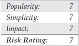
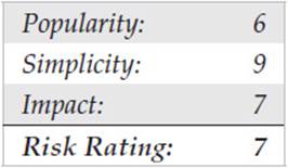
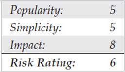
Admittedly, media manipulation attacks have shed risk-rating points over the past few years. UC networks are more often secured by Session Border Controllers (SBCs) and SRTP. Regardless, media manipulation attacks continue to warrant an in-depth look because the large bandwidth differential between audio and video streams results in a substantially greater cost to secure video streams. Consequently, video streams are likely to remain at risk for the next few years.
We will now examine these audio and video attacks independently using hands-on analyses and attack tools.
Audio Insertion and Mixing
The first items in the series of media manipulation attacks we will examine are audio insertion and audio mixing. These attacks involve the insertion or mixing/interleaving of attack audio into an ongoing conversation. The idea here is that one or both parties in a call hear noise, words, or other sound that is malicious or illegitimate. An insertion attack effectively replaces legitimate audio. During the insertion attack, none of the legitimate audio is heard by the user at the targeted endpoint. The original audio is essentially muted.
A mixing attack merges attack audio with the legitimate audio. The user at the targeted endpoint hears the audio transmitted from the other party in the call mixed with the attack audio. If attack audio mixed into a legitimate audio stream is lower amplitude than the legitimate audio stream, the listener interprets it as background noise.
We should emphasize that the tools we developed to demonstrate these attacks are not man-in-the-middle (MITM) tools. Although the legitimate audio packets continue to be exchanged between endpoints, they are also being sniffed by the hacking tools. Specially crafted audio packets are produced in real time and transmitted by the hacking tool to the targeted endpoint. The targeted endpoint receives both the legitimate audio packets and the attack audio packets. The attack is successful when the targeted endpoint’s jitter buffer discards the legitimate audio packets in favor of the attack audio packets, which cause the endpoint to play the attack audio to its user. Figure 16-1 illustrates these attacks.
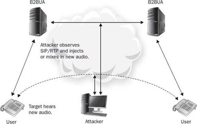
Figure 16-1 Inserting/mixing audio attacks
We first cover the rtpinsertsound and rtpmixsound tools, which are used at the command line and work with any RTP stream, regardless of the signaling protocol. Following this, we cover the Call Monitor and sipsniffer tools, which provide a GUI on top of the rtpinsertsound and rtpmixsound tools (but only work with SIP).
These tools enable many types of attacks. All of them follow the same basic format, but with different audio inserted or mixed in. Here are a few examples that come to mind:
• For any call, insert or mix in background noise to degrade the call quality.
• For any call, insert or mix in derogatory language, making the target think they are being abused.
• For a call to a spouse, mix in background sounds from a bar, poker game, or something else the person should not be doing.
• For a customer support call, mix in abusive phrases, making customers think they are being insulted.
• For stock trading, particularly when a customer is connected to an automated device, insert words such as “buy” and “sell” to see if the order-taking party can be tricked into making the wrong transaction.
Call Monitor lets you manipulate multiple calls. Also keep in mind that you can run multiple copies of these tools, so if you have access to a portion of the network carrying many calls, you can affect any number of them. This includes calls being transmitted to the media gateway and over the wide area network (WAN).
Tip![]()
These attacks target RTP, which is used in virtually all UC environments, including those using proprietary signaling protocols. Although the Call Monitor tool itself only supports SIP, the underlying rtpmixsound and rtpinsertsound tools work directly on RTP, so they can be used when other signaling protocols are used; this includes Cisco’s SCCP.
![]() Inserting and Mixing Audio with the rtpinsertsound and rtpmixsound Tools
Inserting and Mixing Audio with the rtpinsertsound and rtpmixsound Tools
 The first tools we will discuss are rtpinsertsound and rtpmixsound, which are Linux-based command-line tools available from www.voipsecurityblog.com.1 The rtpinsertsound tool inserts/replaces RTP audio messages representing the playback of the prerecorded audio into the target audio stream. The rtpmixsound tool also inserts/replaces RTP audio messages into the target audio stream, but each message is the real-time mixture of the most recently received legitimate RTP message’s audio payload and the next attack prerecorded RTP message’s audio payload. The usage information for the tools is as follows:
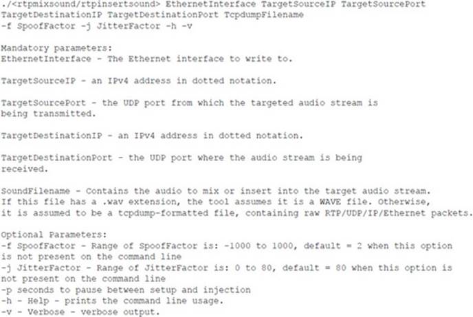
The sound file inserted or mixed into an audio stream must be in a .wav or tcpdump-formatted file specified on the command line. If it is a tcpdump file, it must be composed of sequential RTP/UDP/IP/Ethernet messages, where the RTP payloads are encoded using the G.711 u-law codec (PCMU).
Each tool reads prerecorded audio from the file specified on its command line into memory before attempting to insert or mix that audio into the targeted audio stream. Each tool enforces an arbitrary limit of 30 seconds of prerecorded audio. The audio file is memory resident to avoid a mechanical medium’s delay while the tool attempts to mix or insert it into the target audio stream.
Because neither tool presumes a MITM position, it’s assumed that the receiving UC endpoint is going to receive the legitimate audio stream and the attack audio stream, which will be twice the number of audio packets the receiving endpoint expects. Both tools employ several techniques to trick the receiving VoIP endpoint into using the attack audio rather than the legitimate audio, such as spoofing the RTP protocol header sequence number, the RTP protocol header timestamp, the RTP protocol header synchronization source identification, the UDP protocol header source port, the UDP protocol header destination port, the IP protocol header source IP address, the IP protocol header identification, or the Ethernet protocol header source MAC address.
The reception of a legitimate audio packet from the transmitting VoIP endpoint drives the tools to output the next bogus RTP message based on its prerecorded, memory resident audio. In the case of the rtpmixsound tool, the prerecorded audio is converted from 8-bit, nonlinear G.711 PCMU to 16-bit linear PCM when it is loaded into memory.
The JitterFactor determines when to transmit a packet and is entered as a percentage of the target audio stream’s transmission interval, which when using the G.711 codec is 20 ms. For example, if we have a JitterFactor of 10 on the command line, it will add a two-microsecond delay (that is, 10% * 20 ms = 2 ms). This prevents the attack audio packet from being launched into the audio stream until about 2 ms prior to the time the next legitimate audio packet is expected to be received.
The JitterFactor range is 0 to 80 percent. The default value of 80 percent means to send the attack packet as soon as possible following the reception of the legitimate audio packet triggering the bogus output. Entering a value too close to 0 risks the receiving VoIP endpoint getting the next legitimate RTP packet before the attack RTP packet. Output of attack packets by the tool is close-looped with the reception of legitimate audio packets from the target audio stream.
The JitterFactor command-line argument is needed by both rtpmixsound and rtpinstertsound to compensate for some phones being sensitive to when the attack audio packet is received relative to the next legitimate audio packet. If the next attack packet is output by the tool as soon as possible following the reception of a legitimate packet, some phones will reject it in favor of the following legitimate audio packet. However, if we delay the output of the attack packet until a few milliseconds prior to when the next legitimate packet is expected to be received, the phone will accept the attack audio packet and appear to reject the next legitimate audio packet received a few milliseconds later.
The SpoofFactor increments the numbering for the RTP packets. Although a negative SpoofFactor can be entered, so far we’ve only observed successful spoofing with positive SpoofFactor entries. Although the default value for the SpoofFactor parameter is 2, usually a value of 1 is adequate. Higher values have also been successful (for example, 10 or 20). The phones we’ve been successful in spoofing appear to prefer audio packets with the more advanced RTP header and IP header values.
Only one side of the call can be affected by either tool. The person on the receiving end of the target audio stream hears the inserted/mixed audio. The person on the transmitting end of the target audio stream is oblivious until the receiving end of the target audio stream questions what is happening. For the rtpinsertsound attacks, the legitimate audio is effectively muted until the playback of the attack audio is complete. The advantage of the rtpmixsound tool is that the person on the target receiving end is able to hear the person on the target transmitting end continue to speak throughout the playback of the attack prerecorded audio.
To use either tool, you first need access to the network segment where the call is being transmitted. For the following example, we called extension 2000 from extension 4000. As the call was being set up, we used Wireshark to monitor the signaling to gather UDP ports. We already knew the IP addresses. Here’s an example of where to find the UDP ports in the SIP INVITE and OK requests:
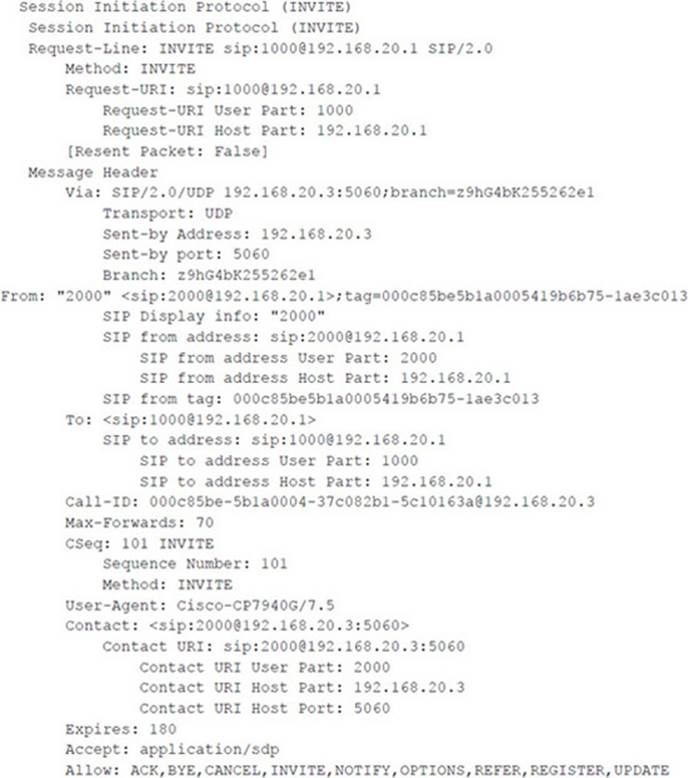
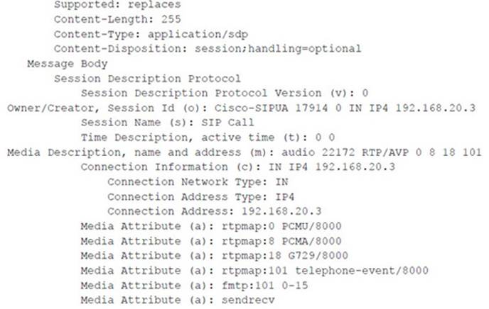
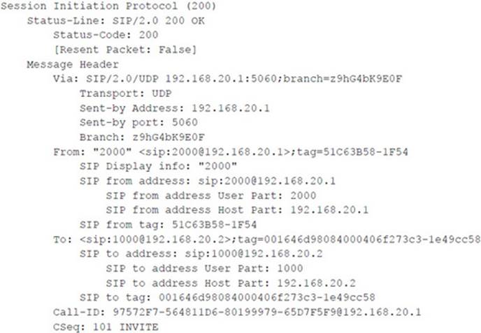
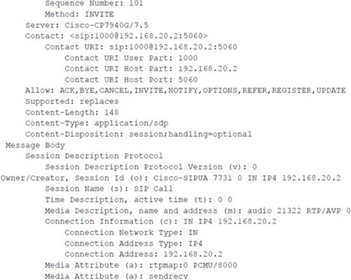
The tools work equally well in a non-SIP environment and were tested with both Cisco SCCP and recent SIP phones. Another easy way to get the ports is to use Wireshark to look at the actual RTP streams. Remember that the tool inserts/mixes audio in only one direction. Here’s an example of a command invocation for this attack:
![]()
This command mixes in the contents of the file sound_to_mix into the RTP stream transmitted from extension 2000 (IP address 192.168.20.3) to extension 1000 (192.168.20.2).
You can run multiple copies of the tools to affect multiple calls or affect both sides of the call. You can also script these media attacks with a delay to insert/mix in repeatedly a short sound, such as a word or noise.
![]() Inserting and Mixing Audio with the sipsniffer and Call Monitor Tools
Inserting and Mixing Audio with the sipsniffer and Call Monitor Tools
The next media manipulation tool we will discuss is sipsniffer. This is a Linux-based command-line tool (www.voipsecurityblog.com) and is designed to be used in conjunction with the Call Monitor tool discussed below. Sipsniffer can insert or mix prerecorded attack audio into a target audio stream.
Sipsniffer represents an evolution of the rtpmixsound and rtpinsertsound tools by adding the following features:
• The ability to interact with the Call Monitor tool
• The ability to sniff SIP and forward it to the Call Monitor tool
• The ability to sniff RTP traffic on the network and forward it to an audio player controlled by Call Monitor
• The ability to launch the teardown tool (discussed in Chapter 15)
Sipsniffer also does not rely on being in a MITM position, which is one of its strengths; however, that fact does limit some attack modalities because sipsniffer does not have direct control of the legitimate RTP audio that continues to stream to the targeted endpoint.
Note![]()
As we demonstrated, both rtpmixsound and rtpinsertsound can be used on their own to mix and insert sound into RTP streams and do not require the Call Monitor tool. However, the Call Monitor tool makes the whole process easier, because it has a slick user interface and does not require you to gather a couple of IP address/port pairs.
The Call Monitor tool (www.voipsecurityblog.com) is a Java-based Linux application that enables a combination of SIP audio attacks as well as audio monitoring capabilities. Call Monitor works in conjunction with the sipsniffer tool, which is responsible for executing the attacks. The tool can tear down existing SIP sessions—and more importantly can launch audio attacks against a targeted endpoint using either of two methods: audio mixing or audio insertion.
The Call Monitor tool suite is very simple to use. Attack audio files are preloaded into sipsniffer and can be customized for each attack scenario. Sipsniffer sniffs and forwards SIP signaling from the network to the Call Monitor tool. Call Monitor interprets the SIP signaling and displays calls to the operator in real time. The Call Monitor can be used to select a call for audio tapping and then launch audio attacks against that call, so long as the call uses the G.711 u-law audio codec for audio streams in both directions of the conversation. Other codecs are not supported. To use the audio attack capabilities of Call Monitor in conjunction with the sipsniffer tool, the operator first highlights a call and selects it for audio tapping. The activation of an audio tap launches the XMMS audio player, which must be configured with a G.711 plug-in on the same system as the Call Monitor. Call Monitor directs sipsniffer to sniff and forward audio streams from the designated call directly to the audio player. The operator can then enable audio attacks. The keyboard is used to select which party of the call (that is, caller or callee) to attack with one of sipsniffer’s preloaded audio files. The operator can time the activation of the attack for maximum effect by listening to the conversation in the audio player as it unfolds. At the attacker’s command, sipsniffer is directed to perform either a mixing attack or an insertion attack against the designated party.
Sipsniffer uses spoofing techniques to ensure that the targeted endpoint is unaware that the legitimate audio stream is being either mixed with or replaced by attack audio. When experimenting with the tool suite, we have discovered that at least a few UC phones are sensitive to bogus audio packet reception. As a result of this sensitivity, certain techniques must be exercised to trick sensitive phones into accepting the bogus audio packets. For example, if the next bogus packet is output by the tool as soon as possible following the reception of a legitimate packet (say, within a couple of hundred microseconds), a Snom 190 SIP phone seems to reject it in favor of the next legitimate audio packet received about 20 ms later. However, if we delay the output of the bogus packet until a few milliseconds prior to the time of day the next legitimate packet is expected to be received by the phone, the Snom 190 phone accepts the bogus audio packet and appears to reject the next legitimate audio packet received a few milliseconds later. A Grandstream BT-100 SIP phone and the Avaya 4602 IP phone (with a SIP load) were not sensitive to when the bogus packet was received within the transmission interval. In order to increase likelihood of attack success, the Call Monitor tool exposes a manufacturer table that is prepopulated with attack parameters found to be most suitable against particular endpoint manufacturers. This list should be used when choosing to target a particular endpoint in order to maximize the success of the audio attack. You can adjust the SpoofFactor and JitterFactor, as described previously for rtpinsertsound and rtpmixsound to ensure that the target accepts the attack packets.
Sipsniffer can target both sides of the conversation concurrently. The operator can select a party in the call such as the caller (that is, the From side of the call) and launch an audio attack. The operator can then target the other party (that is, the To side of the call) and launch another audio attack against the callee while the first attack continues to execute.
To use Call Monitor and sipsniffer effectively, you first need access to the network segment where the call is being transmitted. Gaining access to a moderately secured network can be extremely easy or nearly impossible. Currently, our tools for audio mixing/insertion rely on the ability to monitor the required SIP and RTP traffic using a promiscuous interface—namely, a network setup whereby the host can effectively sniff traffic. When dealing with packet-switched networks, these tools cannot operate unless a physical Layer 2 hub device is injected or a MITM attack is accomplished first to spoof the endpoints/switches into forwarding traffic to the host running the sipsniffer tool. Here are some screen captures of the Call Monitor tool and console output of the sipsniffer tool and teardown tool, showing them in action.
Figure 16-2 illustrates how the Call Monitor tool appears when started (and with a few columns adjusted). The Call Monitor tool consists of three sections: the top section is the toolbar, the middle section is where detected calls are displayed, and the bottom section is where instructions, error messages, and the status are displayed. The channel number (that is, row) assigned to a call is arbitrary.
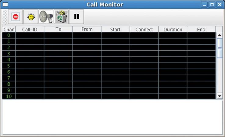
Figure 16-2 Call Monitor appearance when started and columns rearranged/resized
The upper-left toolbar button (the red stop sign icon with a dash) is the Call Teardown button. You may attempt to tear down a call in the “Connected” state by selecting (that is, left-clicking) its row (that is, channel), by selecting a consecutive group of calls (that is, left-click and drag or left-click and press SHIFT,) or by selecting a widely dispersed set of calls using left-clicks in conjunction with the CTRL key in a standard fashion. After selecting a call or group of calls, left-click the Call Teardown button. If you happen to tear down a call that is being audio tapped, the audio tap is terminated. Because only a call being audio tapped is eligible to be audio attacked, any in-progress audio attacks are also terminated.
A call is in the “Connected” state when it has been answered (that is, a time is displayed in the call’s Connect column and no time is displayed in the call’s End column).
When a call is ended (either in the normal course of events or because you successfully tore it down), the foreground color of the call’s display changes from green to orange. The call’s display persists for a short time (30 seconds) before it is removed from the display.
The button with the yellow smiley face wearing headphones activates Audio Tap for a selected call in the “Connected” state. Only one call can be audio tapped at a time. As you’ll see in a moment, when Audio Tap is successfully activated, the button icon toggles to a blue smiley face with a gleeful toothy grin. That means the character of the button has toggled to Audio Tap Disable. If the XMMS audio player GUI is not already open, successfully activating Audio Tap for a call also provokes the XMMS audio player GUI to open. The sipsniffer tool is commanded by the Call Monitor tool to stream RTP packets from each side of the call to sockets opened by the XMMS audio player’s G.711 plug-in.
The button with the megaphone icon is the Audio Attack Enable button. A call must first be activated for Audio Tap before it can also be enabled for audio attacks. When Audio Attack has been successfully enabled, the megaphone is overlaid with a red circle and diagonal slash. This indicates the character of the button has toggled to Audio Attack Disable. Audio attacks may then be launched against the selected call in accordance with keyboard commands. Keyboard commands are discussed in a moment.
The next button’s icon looks like a phone being deposited into a recycle bin. It’s the Call Trash button. It’s possible the Call Monitor tool might not always accurately represent the status of calls. Suppose the Call Monitor tool and the sipsniffer tool are located on different platforms and there is a brief network outage. The Call Monitor tool might miss a message from the sipsniffer tool that a call has ended. The Call Trash button is used to dispose of selected calls in which the operator might have lost confidence. The call itself—if it is still active—is unaffected. If you trash a call that is activated for Audio Tap and enabled for Audio Attack, those facilities are ended and the respective button icons toggle to their former state. The last button is a Pause button, which has not been implemented.
Figure 16-3 infers that the sipsniffer tool is running and has forwarded sniffed SIP signaling to the Call Monitor tool. This screenshot was taken 27 seconds after the call appeared in Chan 0. The call was answered a couple of seconds after it started and thus it is in the “Connected” state. The caller is x7500 in the 10.1.2.164 domain. The callee is x4500 in the same domain. Calls are distinguished from each other by the Call Monitor tool purely on the basis of the respective call’s SIP Call-ID. The last column displays a call’s SIP Call-ID. It is a GUID whose value is required by the SIP protocol to be unique over all time and space. The Call Monitor tool and the Call-ID column can be resized by the operator to observe the entire Call-ID.
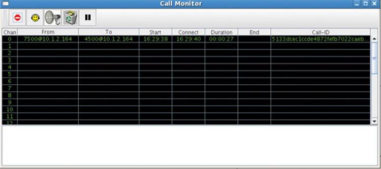
Figure 16-3 Call Monitor displaying a sniffed call in the Connected state
Figures 16-4 and 16-5 indicate the operator clicked the Audio Tap button. The icon of the button changed to the gleeful blue smiley face from its former yellow smiley face. Message #1 (that is, Chan 0 Audio Tap On) has appeared in the status area. The XMMS audio player GUI popped open and tapped audio has been streaming to the audio player for one minute and nine seconds.
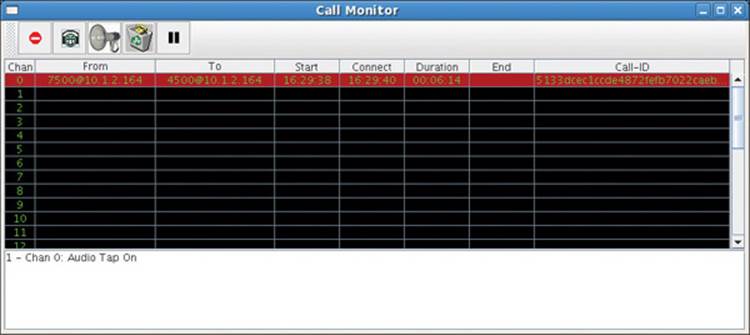
Figure 16-4 Selected call is audio tapped.
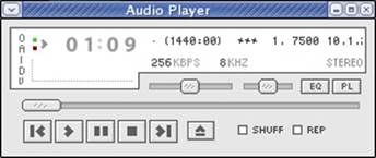
Figure 16-5 XMMS audio player receiving tapped call’s audio
Figure 16-6 reports that the operator clicked the Audio Attack Enable button. The icon of the button has been overlaid with a red circle and a slash to indicate it is now an Audio Attack Disable button. The “From” column is highlighted in red. This indicates keyboard audio attack actions will target the caller side of the call (that is, the audio heard by the caller). Message #2 in the status area states that condition. It also provides instructions to the operator on how to launch an audio attack. Pressing the right arrow key alters the target of the next audio attack to the callee side and the “To” column is then highlighted. The message goes on to state the operator can issue an attack against the selected side of the call by pressing one number key (that is, 0 through 9). However, an audio attack only proceeds if attack audio has actually been preloaded into the sipsniffer tool corresponding to that numbered slot. The position of the SHIFT key when the number key is pressed dictates whether the audio attack is a MIX attack or an INSERT attack (that is, a replace attack). If the operator launches an attack, he’ll be able to hear that attack audio through the XMMS audio player and the reaction (if any) of the parties in the call.
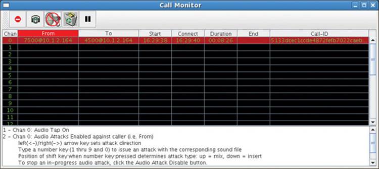
Figure 16-6 Audio tapped call also enabled for audio attacks against the caller
The Figure 16-7 status area demonstrates that the operator launched an audio attack against the caller. The operator pressed the keyboard’s number 1 key without pressing the shift key. Thus, the Call Monitor tool commanded the sipsniffer tool to transmit spoofed audio packets to the caller that were a mix of audio from the sipsniffer tool’s preloaded sound file #1 and audio being sniffed from the callee. If the attack is successful, the caller’s phone discards the legitimate audio streaming directly to it from the callee’s phone and instead plays back the attack audio from the sipsniffer tool, which is a mix of the sniffed callee audio and the attack audio.
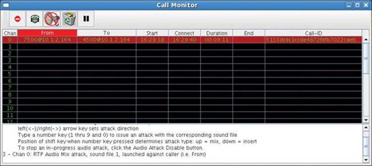
Figure 16-7 Audio mix attack was launched against caller using sound file #1.
The Figure 16-8 status area indicates the operator has turned his attention to the callee by pressing the keyboard’s right arrow key. The “To” column is now highlighted.
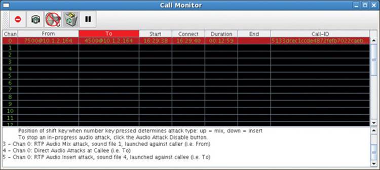
Figure 16-8 Callee selected for future audio attack
The Figure 16-9 status area reports the operator did launch an audio attack against the callee. He pressed and held the keyboard’s shift key while also pressing the number 4 key. Thus, the Call Monitor tool commanded the sipsniffer tool to transmit spoofed audio packets to the callee using the audio from the sipsniffer tool’s preloaded sound file #4 and values from the headers of audio packets being sniffed from the caller. If the attack is successful, the callee’s phone discards the legitimate audio streaming directly from the caller to the callee and only plays the attack audio streaming from the sipsniffer tool to the callee, which only contains the attack audio and no caller audio. Essentially, an insert attack is intended to effectively mute audio from the non-targeted side of the call.
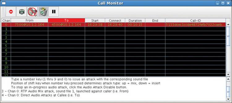
Figure 16-9 Audio Insert attack launched against callee using sound file #4
Figure 16-10 illustrates that the operator has disabled audio attacks and audio tapping, in that order, by clicking the Audio Attack Disable button (thus returning it to its former presentation as an Audio Attack Enable megaphone icon without the red circle and slash) and then clicking the Audio Tap Disable button (thus returning it to its former presentation as a yellow smiley face with headphones). The status area also reports these actions.
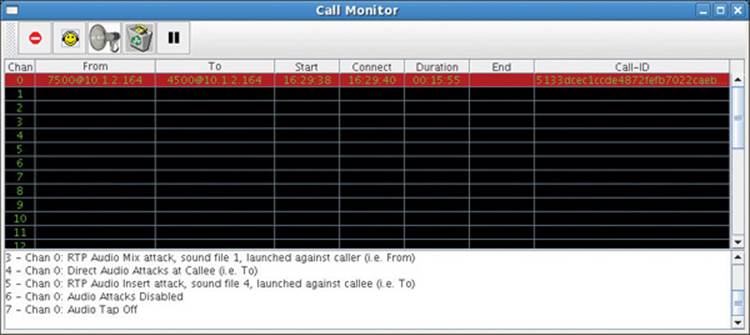
Figure 16-10 Audio Attack and Audio Tap are once again disabled.
The status area in Figure 16-11 informs us that the operator clicked the Call Teardown button and that the teardown action is underway. When successful, the End column is data filled with the end time, the Duration column stops incrementing, and the foreground color of the call’s data changes to orange. The channel is cleared 30 seconds later.
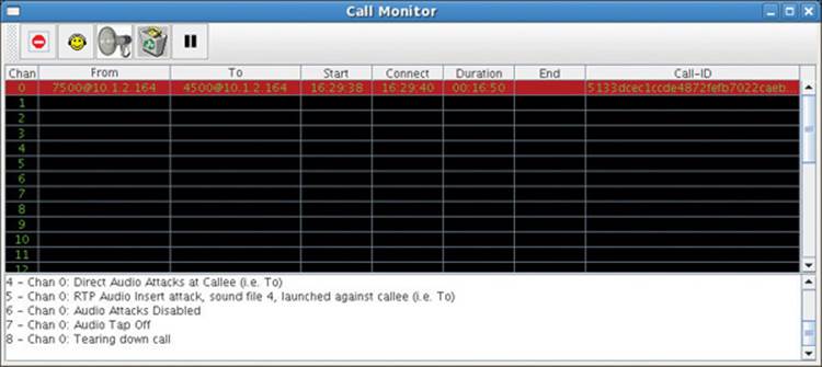
Figure 16-11 Teardown underway
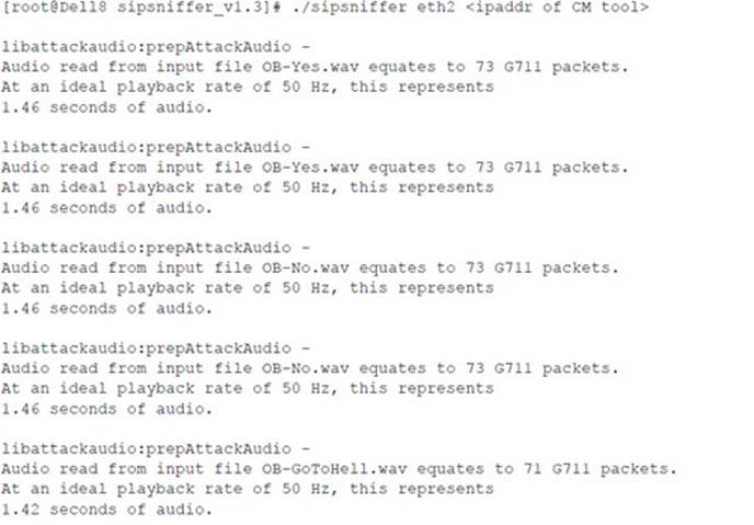
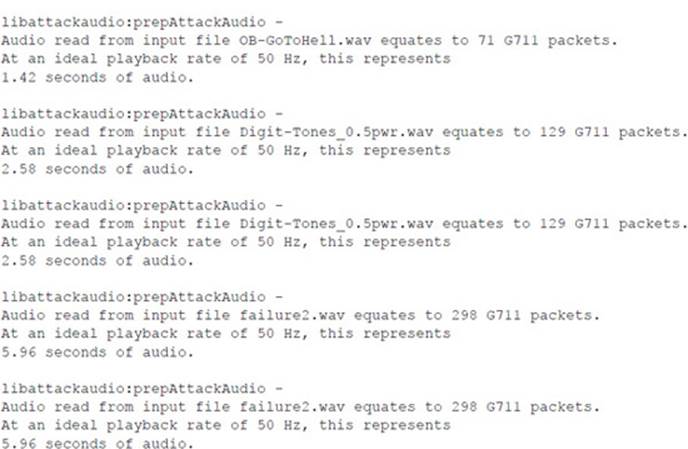
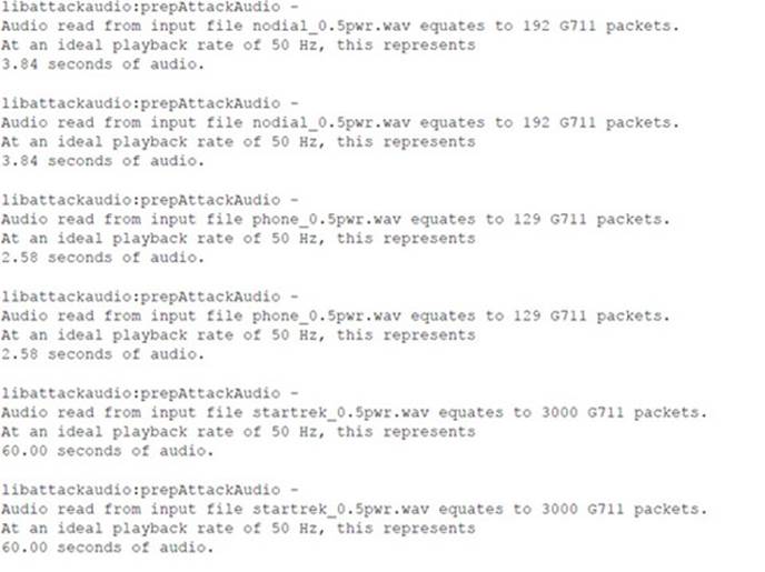
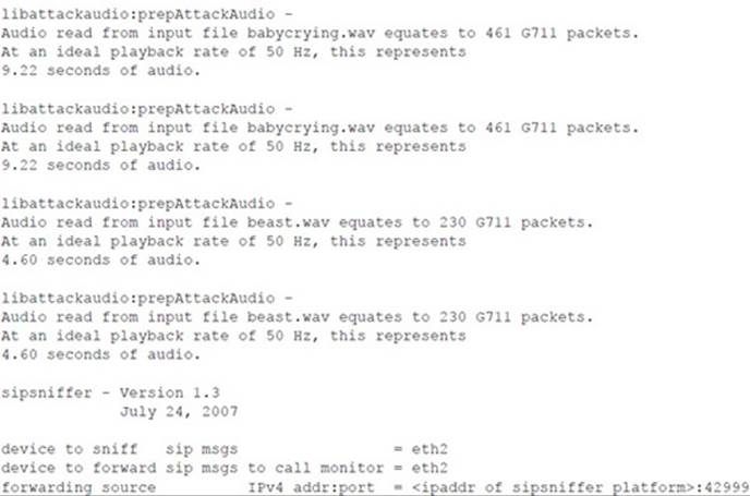
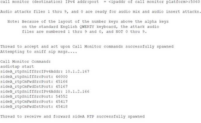
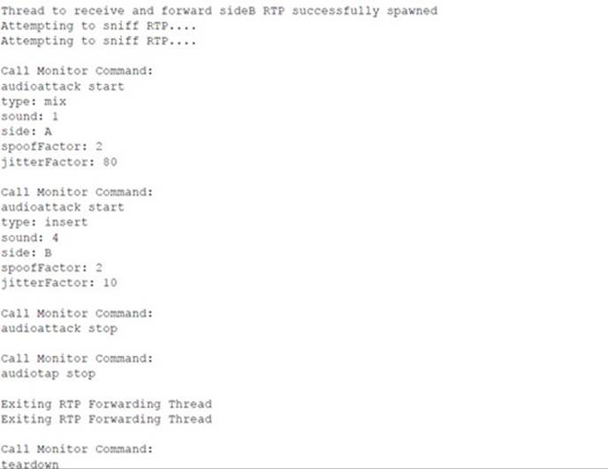
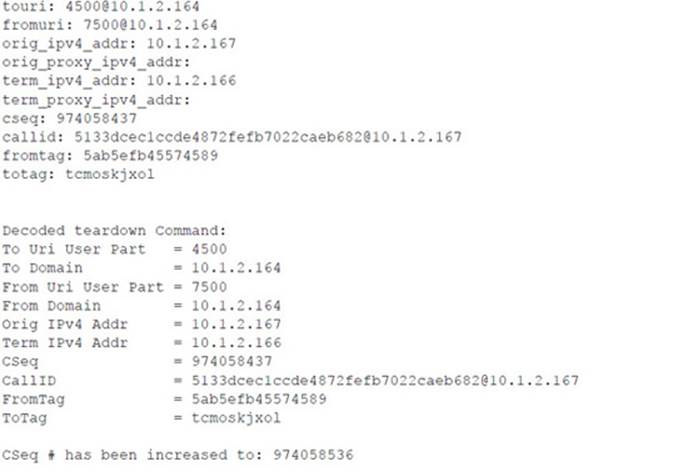
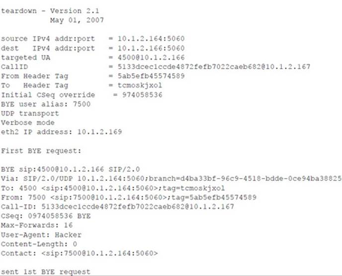
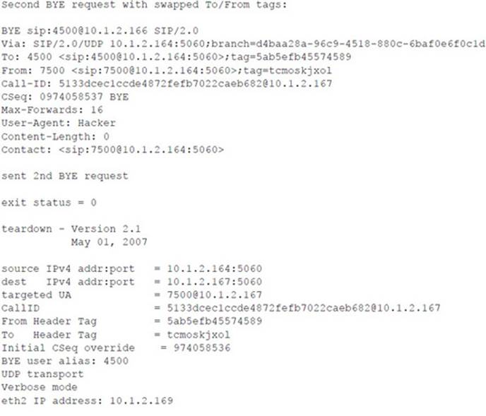
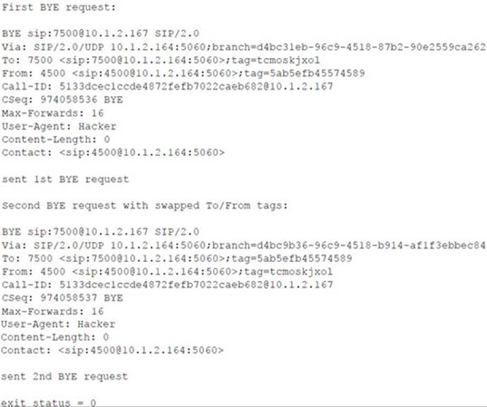
Following is the console output of the sipsniffer tool and the teardown tool during the Call Monitor session. When the sipsniffer tool is started, an attack_audio.conf file is consulted to identify any attack audio files to preload into the tool. Each audio file (up to 10) is preloaded and conditioned twice: once in preparation for a mix attack and once in preparation for an insert attack. At the end of the Call Monitor session when the call is torn down, the sipsniffer tool receives the teardown command from the Call Monitor tool and invokes the teardown tool twice. The teardown tool must be colocated with the sipsniffer tool. Each invocation of the teardown tool results in the production of two slightly different SIP BYE requests. Two requests are transmitted to the callee, and two requests are transmitted to the caller. Only one of the endpoints needs to accept a BYE request in order to effectively end the call.
![]() Audio Insertion and Mixing Countermeasures
Audio Insertion and Mixing Countermeasures
Several countermeasures address these media manipulation attacks, as described in the next few sections.
Encrypt/Authenticate the Audio
You can stop RTP manipulation attacks to some degree by encrypting the audio. If the audio is encrypted, it is impossible to read in the audio and mix in new sounds. You can insert new audio, but even if the target can be tricked into accepting it, it will sound like noise when it is decrypted. All of this assumes that the RTP packets are not authenticated; otherwise, anything generated by our tools will fail to authenticate and will likely be dropped at the next media control point, such as an SBC. Most enterprise-class UC products offer RTP encryption and authentication as an option; however, this is not commonly used. In contact centers, where sensitive conversations are being held, encryption is used in some cases, but not across the board.
Secure RTP (SRTP; www.ietf.org/rfc/rfc3711.txt) is a standard providing encryption and authentication of RTP and RTCP. SRTP provides strong encryption for privacy (prevents mixing) and optional authentication that allows endpoints to differentiate legitimate from bogus RTP packets. A substantial number of vendors support SRTP as an option, but again, it is not commonly implemented.
Some good news: Microsoft Lync uses SRTP by default. We have seen SRTP being used more and more in government and financial enterprises. However, it is virtually never used on SIP trunks (which carry RTP) from untrusted networks. So even if SRTP is used for media inside an enterprise network, it will usually be unencrypted out in the untrusted network.
Another option is to use IPSec to encrypt all the RTP at layer 3. In this model, there is no need to use SRTP, and these tools will not operate correctly. IPSec has deployment challenges; however, we do see it deployed in some cases for SIP trunks connected to service provider MPLS networks.
IPSec or SRTP would limit the attack vectors of these tools, forcing attackers to choose locations that do not have them deployed.
ZRTP, promoted by Phil Zimmermann of PGP fame, is another option for encrypting RTP streams.
Use VLANs to Separate Voice and Data
Most enterprise-class UC deployments use VLANs to separate voice and data. Although VLANs are designed primarily to assist with performance, they also provide a layer of separation and security. With VLANs and properly configured LAN switches, you can make it more difficult for a PC to monitor and insert bogus RTP packets.
The use of softphones on PCs and UC in general can defeat the use of VLANs as a security measure. When a softphone is used, RTP packets, presumably from the softphone, must be accepted by the network.
VLAN separation is not the be-all and end-all because it is fairly easy to hop onto VLANs using tools that we describe later. Mitigation of VLAN hopping is typically done at the switch or VLAN-aware IPS point.
Audio Manipulation Detection
Any device, including a hardphone, softphone, media gateway, IP PBX, or SBC could monitor the RTP for packets with repeated sequence numbers, which could indicate an audio manipulation attack. For example, if every packet comes in twice with the same sequence number, but different audio payload content, an attack may be going on. To our knowledge, no detection of this kind exists.
![]() Video Dropping, Injection, and DoS with VideoJak and VideoSnarf
Video Dropping, Injection, and DoS with VideoJak and VideoSnarf
Media manipulation attacks are also applicable for video. These include injection and dropping attacks that rely on a MITM attack position. They can replay, drop, or spam a video session. The idea here is that one or both parties see altered, garbage, or no video. Replaying of video involves capturing the original video stream and replaying against the target one or more times. These attacks are also used to create a denial of service (DoS) that involves random, crafted video and causes the video stream to become corrupted for a brief period. Dropping of video affects the quality of service (QoS). Figure 16-12 illustrates these attacks.
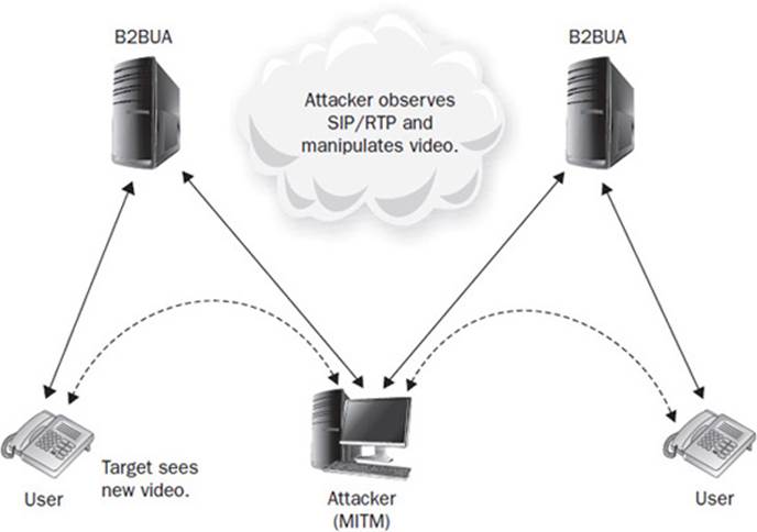
Figure 16-12 Video manipulation
These tools enable many types of attacks, all of which follow the same basic format. Here are a few examples:
• For any call, insert random pictures or video frames to make the call quality video poor.
• For any call, insert random pictures or video frames to make the call video contain video advertising/SPAM.
• For any call, insert derogatory images, making the target think they are being abused.
• For any call, drop video from the caller to the callee and insert a new stream from the callee to the caller, allowing communication with the caller. The caller is tricked into thinking he is talking to his stockbroker while the actual broker is left with a black screen. The broker ends her session soon after realizing something is wrong with the call. Being a MITM attack, any session teardown requests are intercepted and blocked, thus keeping the spoofed video session up with the caller indefinitely.
These attacks irritate, insult, and confuse the target. Certain attacks seriously undermine the credibility of individuals or enterprises. Attacks that add or drop video make users think the UC system is not performing well (QoS). On the extreme end of the spectrum, attacks can be used to perpetrate financial fraud.
VideoJak (http://videojak.sourceforge.net) is a Linux-based command-line tool developed by Sipera’s Viper Lab that stages video attacks such as video replay, video QoS, and video DoS. VideoJak acts as a MITM system where all RTP and signaling is sent to and from the host running VideoJak. This MITM capability enables VideoJak to manipulate the video streams in real time.
VideoJak differs from the sipsniffer tool in that it has full control of the legitimate RTP and signaling streams prior to delivery to the other party. VideoJak manipulates RTP header information of the legitimate stream and adds malicious video atop the legitimate video stream without need for spoofing. This feature of VideoJak replaces the need to use a SpoofFactor with manufacturer-specific values such as those in sipsniffer to trick the target into using certain RTP packets over others. VideoJak is able to target both sides of a session concurrently, which is very useful in staging more complex attacks, as outlined later.
VideoSnarf (http://ucsniff.sourceforge.net/videosnarf.html) was also developed by Sipera’s Viper Lab. It takes an offline Wireshark capture file as input and then outputs media streams (RTP sessions), including common audio codecs as well as H264 video support into a new Wireshark capture file. VideoSnarf is used to support VideoJak in video replay attacks. This tool is extremely useful for extraction of RTP streams from Wireshark captures.
To use VideoJak effectively, you first need access to the network segment where the call is being transmitted. Gaining access to the network topology can be extremely easy or nearly impossible, depending on the network. Luckily, VideoJak automatically executes ARP poisoning and VLAN hopping to get in a MITM position.
![]() Video Dropping, Injection, and DoS with VideoJak and VideoSnarf Countermeasures
Video Dropping, Injection, and DoS with VideoJak and VideoSnarf Countermeasures
You can employ several countermeasures to address these video manipulation attacks. All of the countermeasures described for audio apply as well. We briefly cover how encryption and authentication differs for video.
Encrypt/Authenticate the Video
You can stop video manipulation attacks to some degree by encrypting the video (as you would with the audio). If the video is encrypted, it is impossible to read in the video and manipulate it. Replaying the same encrypted video is possible unless RTP authentication is employed. You can insert video, but even if the target can be tricked into accepting it, it will look like garbage when decrypted. Note, however, that because of the much greater amount of bandwidth used by video, especially for high-end telepresence systems, the processing cost of securing video is much higher.
Media “Steganophony”
A class of attacks is emerging in the UC space that relies on security techniques from the data world. Media steganography is a technique that is used in order to leak data into and out of organizations. The class of attacks presents both exfiltration and infiltration capabilities via the use of steganographic techniques with RTP. For this section, the popular term data leakage will be used in association with steganography.
Data leakage is already a hot topic in the data world due to the risk it poses to the enterprise. One example of the potential problem data leakage from attackers poses is that it provides the means to exfiltrate intellectual property from an enterprise undetected. Many vendors offer technology to monitor and mitigate data leakage. The industry term for these technologies is data leakage prevention (DLP).
In the vast majority of cases, DLP involves the monitoring of data plane communication protocols looking for data that is deemed illegitimate by a particular organization. The protocols include HTTP, FTP, and Telnet. Unfortunately, modern applications predominantly encrypt all data plane communications via protocols such as HTTPS, SFTP, and SSH. In this environment, traditional DLP techniques are ineffective because packet contents cannot be inspected. As a result, organizations ban any and all traffic from particular applications as a last resort. For example, an application such as TeamViewer is easily blocked from leaving a corporate network by targeting its use of fixed ports. However, TeamViewer’s inspection is impossible due to the use of strong encryption. Steganographic techniques can be used to transfer documents and data over a variety of other IP protocols as well.
The goal of steganography is the hiding of secret data in users’ normal data transmissions, ideally so it cannot be detected by other parties. One of the most popular steganographic techniques is the use of a covert channel, which enables manipulation of certain properties of the communications medium in an unexpected, unconventional, or unforeseen way. In the past few years, the interest in steganographic methods has grown considerably.
In the UC world, data leakage is emerging as a formidable threat, albeit in different forms due to differing architectures and communication protocols. The term steganophony is used to describe UC-specific steganographic attacks over these networks. The most effective data leakage attack in UC targets the primary communications channel or media plane (RTP). Although data leakage is possible over the signaling plane, it is less effective due to infrequent packet transmission rates as compared to RTP’s numerous packets, which are a requirement of effective steganophony. As such, the focus of our analysis is RTP. Because RTP is a real-time protocol, steganophony is perfectly suited due to the high volume of packet exchange between parties at steady rates. Most SBC/IPS/firewall vendors have no countermeasures to deal with these types of attacks, elevating their impact relative to the aforementioned audio and video mixing attacks.
Several data leakage attacks exist for RTP. We cover the most popular techniques in some detail and follow up in later sections with implementation and detectability techniques. We describe steganography next to set a context for the attacks that follow.
Steganography involves two broad categories related to network transmissions. We examine these categories to prepare a more articulate contrast with UC steganophony.
To assist, we introduce the term data leakage throughput (DLT). The purpose of steganophonic attacks is the transfer of covert data over the network. DLT is a measure of how many bits per second of data a particular attack can transfer if executed. It represents a high-level barometer of the effectiveness of data leakage attacks.
Steganography techniques are organized into two classes—packet content and packet time manipulation—and are illustrated in Figure 16-13.
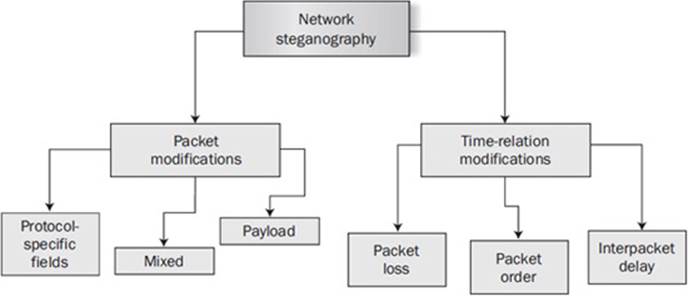
Figure 16-13 The two classes of network steganography
These steganographic methods modify packets such as network protocol headers or payload fields and methods that modify packets’ time relations (for example, by affecting sequence order of the packet arrival).
Steganophony is differentiated with specialized techniques in each of the categories and presents an entirely new category specific to UC, as shown in Figure 16-14. The first steganophonic subgroup relies on packet modification, as shown on the left of the diagram. Examples include the usage of packet fields in RTP and SRTP, including the IP and UDP that supports the upper protocols. Direct manipulation of the payload includes techniques such as the use of watermarking or silence injection descriptor (SID) frames. Lastly, a mixed group includes technology-specific techniques that target UC over wireless, such as HICCUPS (Hidden Communication System for Corrupted Networks).
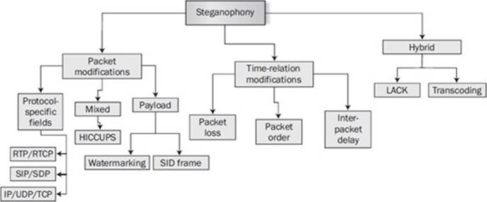
Figure 16-14 Steganophony categories
Techniques that modify packet headers have the highest DLT because RTP involves tens of packets per second. Fortunately, the detection of this group is fairly easy. Techniques that change RTP payload have a low DLT because they operate in a constrained environment where minimal perturbations of media payload results in sufficiently perturbed audio or video. Consequently, those techniques are harder to detect because they involve rigorous RTP payload inspection.
The second steganophonic group relies on packet time. Examples include usage of packet sequence and RTP/RTCP packet delay and loss. Techniques that modify packet timing or arrival offer low DLT because data is transmitted at infrequent intervals and not per packet. Unfortunately, the detection of this group is difficult because it requires cross-packet understanding of the RTP stream and it is easy to implement by attackers. The rule of thumb for this category of steganophony is that data leak detection is inversely related to implementation difficulty and DLT is low for all techniques.
The last steganophonic group is UC specific. The hybrid group involves a combination of the aforementioned two groups. In recent years, academic study produced two very interesting and UC-specific steganophony techniques, the most recent having the highest risk of all media attacks due to its detection complexity and extremely high DLT. The two techniques are called LACK (Lost Audio PaCKets steganography) and transcoding. Both techniques are difficult to detect, hard to implement by attackers, but yield excellent DLT. The next sections outline in detail each of the aforementioned groups. We follow the section with a countermeasures section, which is similar for all the attacks.
![]() RTP/RTCP Header Field Manipulation
RTP/RTCP Header Field Manipulation
RTP has several fields that can be used for the transport of information, as shown in Figure 16-15.
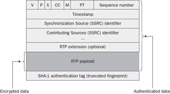
Figure 16-15 RTP header
The relevant transportation fields of the RTP header include the following:
• Padding field (defined by bit 2) Some encryption algorithms require padding at the end of the RTP payload. When the padding bit is set, extra bytes are valid after the payload. These extra byes can be used to carry information.
• Header extension (defined by bit 3) RTP allows for an arbitrary amount of header extensions preceding the payload. When the extension bit is set, extra embedded RTP headers can be added together in sequence. There is no specified limit on the amount. Information can be embedded in these headers.
•Values of the Sequence and Timestamp fields Due to the fact that both these values must be random for the first packet of stream, information (albeit minimal) can be embedded there as well.
As a side note, the transfer of information using the RTP least significant bit (LSB) of the Timestamp field is not a feasible vehicle as might be described in public literature. Recent analysis of this method proves that it is flawed. The detection of this technique is easy and is unlikely to be seen in enterprise networks that deploy SBCs or UC-aware IPS/firewall applications that inspect and normalize RTP headers.
For the preceding fields, a typical call using the G.711 codec at a rate of 50 packets per second can expect to transfer more than 100 bits per packet, resulting in 5,000 bits per second of DLT. The amount of transfer is proportional to the detection probability in this case, because embedding too much data in the RTP header, effectively bloating it, can set off alarms on SBC/IPS/firewall applications.
In most RTP-based systems, RTCP is used to monitor QoS between parties. RTCP is used to derive the Mean Opinion Score (MOS) of the call. MOS is useful in characterizing the “quality” of the media exchange between parties. RTCP has two types of packets and various fields within those packets that can be used to transfer information. Refer to Figure 16-16 for the structure of the two RTCP packet variations.
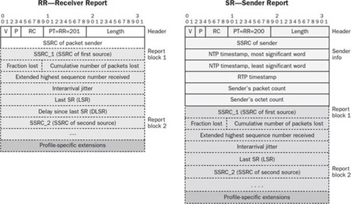
Figure 16-16 RTCP packet variations
RTCP exchange is based on a periodic exchange of pairs of packets between all parties in a call. These include the Receiver Report (RR) and the Sender Report (SR). Although the exchange rate of these messages is usually no more frequent than five seconds, the packets themselves hold large payload sizes in what are called report blocks. The infrequent transmission rate of these packets is somewhat offset by the larger quantity of leaked data per packet. The maximum size of a report block per stream is 160 bits in either an RR or SR. Using these fields, a typical call involving two streams at five-second RTCP intervals can expect to transfer 64 bits per second of information. Using this technique comes at the expense of crippling the RTCP function, which could alarm security applications, so the technique has a low DLT efficiency relative to its complexity and cost.
In general, steganophony via RTP/RTCP headers is easy to detect and is unlikely to be seen in real UC networks that deploy SBCs or UC-aware IPS/firewall applications. It is important to stress that the DLT realized from RTP and RTCP techniques can be compounded with the amount of DLT realized from general steganography in the IP and UDP headers supporting them.
![]() SRTP/SRTCP Security Field Manipulation
SRTP/SRTCP Security Field Manipulation
RTP and RTCP have several security fields that are used when secured over SRTP. Refer to Figure 16-15 and Figure 16-16 for the structure of an RTP and RTCP packet. The most effective field for steganophony is the authentication_tag field. This field is between 32 and 80 bits long. It can be used to carry information and is almost impossible to detect due to the random nature of the cryptographic mechanism using the field. The party with correct decryption cipher keys will be the only party able to detect illegitimate data in this field. However, since the receiving party in a steganophonic attack is typically controlling the equipment, the presence of illegitimate authentication_tag data is not important because transport of covert information in this field is the goal.
![]() Speech Silence Codecs
Speech Silence Codecs
Enterprise UC networks value RTP bandwidth conservation. Various RTP codecs exist that offer bandwidth savings via payload compression. For example, G.729 uses one-eighth of the RTP payload bandwidth as G.711. The nature of most UC communications involves conversations where one party is speaking at a time. During this time, other parties are typically silent. Codecs such as G.711 encode silence as full RTP payloads of zeros. The amount of silence across all call participants for the duration of the call can exceed 40 percent.
Bandwidth conservation strategies that target silence are effective at reducing overall RTP bandwidth. The ability to encode periods of silence using special packets that dictate how much silence should be “played” by an endpoint reduces bandwidth significantly. These special packets are called Silence Insertion Description (SID) RTP packets. The size of the SID RTP payload varies but rarely exceeds 20 bits. From a steganophony perspective, the SID frames are used as a vehicle to transfer information.
Using SID, a typical call at a rate of one SID packet per second can expect to transfer 20 bits per second. Although that DLT is low, the rate of the SID frames can vary with no set “standard” of what a normal SID rate should be. Additionally, this technique is extremely easy to implement by attackers because it involves basic packet-creation capabilities.
In general steganophony via SID is easy to detect and easy to implement. Given the sensitivity to RTP bandwidth in many enterprises, the use of SID is high and as such the technique is feasible and likely to be seen in real UC networks. It is important to stress that the DLT realized from SID can be compounded with the amount of DLT realized from steganography/steganophony in the RTP/RTCP, IP, and UDP headers supporting them.
![]() LACK
LACK
LACK is a steganophony technique specific to UC and the behavior of RTP. The main premise behind LACK is that RTP offers a small window of opportunity for packets to traverse the network between parties, and packets that do not make it in a respectable amount of time are considered invalid and discarded by the receiving party. Usually this delay needs to exceed the jitter buffer delay plus some factor that is specific to receiving party. Interestingly, the transmission of RTP packets that are “already late” at the moment of creation is completely legitimate. Figure 16-17shows how LACK would take place.
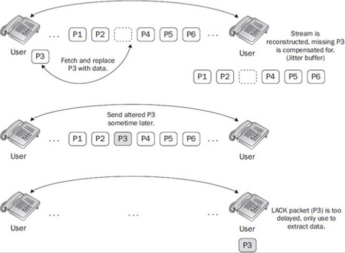
Figure 16-17 LACK operation
Attaining an efficient DLT using this technique is dependent on the codecs used and the network’s sensitivity to media loss. Namely, if every second a few packets are chosen for LACK and the codec can handle these types of losses, the DLT can be substantial. A typical call using the G.711 codec at a rate of 50 packets per second with a codec that handles loss up to three packets per second can expect to transfer 480 bits per second. The DLT from this technique is substantial, coupled with the fact that detection of LACK is not readily obvious because it would involve an application having to interrogate every RTP packet of every stream, taking into consideration the codec and its resiliency to delay. In general, there is no obvious and easy way to declare a RTP packet being too “late” if it arrives a few jitter buffers after it was supposed to.
In general, steganophony via LACK is difficult to detect and easy to implement, and so is likely to be seen in real UC networks. It is important to stress that the DLT realized from LACK is in addition to the amount of DLT realized with the use of steganography and steganophony in RTP/RTCP, IP, and UDP headers supporting them and other packets, which are not chosen for LACK in the streams. In aggregate, one could expect over 10,000 bits per second of DLT through combinations of IP/UDP, RTP/RTCP, and LACK-based techniques for calls.
![]() Media Transcoding
Media Transcoding
A recent steganophony technique involves the manipulation of the media payload as it relates to codec transcoding. This technique is extremely efficient, hard to detect, and offers extremely high DLT. As such, it is very likely to be seen in enterprise UC networks. Transcoding is applicable for both audio and video, whereas certain aforementioned techniques are specific to audio only. This makes its application more relevant and future proof, given the large migration to video by many enterprises.
Transcoding relies on compression algorithms for the legitimate media payload and the covert information. Namely, the RTP payload type is determined and its payload is transcoded to a matching compressed codec that offers minimal loss after transcoding; for example, G.711 to G.729 yields an 8× compression ratio with minimal loss of quality. Thus, a 160-byte payload is transformed to a 20-byte payload. The remaining payload space (140 bytes) in the original RTP packet after the transcoding is used for the covert information.
To further improve the DLT, the covert information in question is compressed using a data algorithm such as gzip, which typically offers a 3× compression factor. In the preceding example, this yields 420 bytes of storage for covert information per packet. That is an extremely large amount of storage with respect to steganophony techniques.
Under transcoding, a typical call using the G.711 codec at a rate of 50 packets per second compressed to the G.729 codec yields an incredible 168,000 bits per second DLT. To put this in perspective, it is 15× more DLT than when using all of the prior steganophony techniques outlined previously combined. Figure 16-18 outlines the basic premise behind the transcoding technique for an RTP packet.
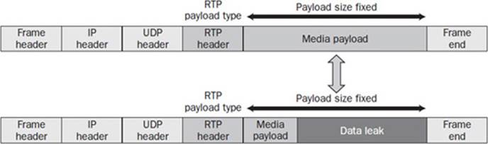
Figure 16-18 Transcoding and the RTP packet header
Incredibly, the use of SRTP has no impact on this technique because the SRTP media payload can be compressed. Because the receiving party in a steganophonic attack is typically controlling the equipment, the presence of illegitimate payload data is not important because extraction of the covert information is the goal.
In general, steganophony via transcoding presents the most effective and dangerous media attack vector with respect to data leakage. The implementation of this technique is bound by the processing requirements of transcoding and compressing media in real time. The detection of transcoding is extremely difficult unless sophisticated RTP packet payload inspection is present. Even if the payload was to be inspected, it is very difficult for a system to differentiate good media from compressed covert information, which stresses the potency of this attack technique.
Several steganophony techniques that are relevant to UC have been presented. Certain techniques prove more effective than others, and when these are combined together it is possible to achieve an effective DLT of nearly 175,000 bits per second! To put that number in perspective, you could covertly transfer 21,000,000 bits in a two-minute conversation! How quickly can sensitive documents be transferred at that rate?
![]() Countermeasures
Countermeasures
For RTP, payload inspection is extremely processor-intensive due to high packet-transmission rates. Most security applications only inspect RTP headers. Mixed steganophonic techniques rely on low-level access to hardware systems, offer medium DLT, and are hard to detect. However, we believe that hardware programmability requirements make it extremely unlikely that attackers will exploit them in an enterprise UC network. Moreover, techniques such as HICCUPS that depend on wireless LAN technologies are rarely present in UC enterprises other than at the edge or endpoint access side, thus making the technique interesting but not realistic. The rule of thumb for this category of steganophony is that data leak detection is directly related to implementation difficulty whereas DLT varies independently across the attacks’ techniques.
Summary
Audio and video manipulation is a serious attack because this type of data is the very reason that VoIP and UC exist (audio in particular because it is part of all voice and video calls). RTP is the ubiquitous protocol used to carry audio and video, so attacks can be used in virtually any UC environment, regardless of the vendor, signaling protocol, and so on. Although audio attacks are the most common, as video continues to gain in popularity, the attacks against it will become more and more common. Stenography can be an issue for exfiltration of data and transmission of malware. This is likely a serious issue for government and enterprises with significant proprietary data. Countermeasures include the use of encryption, SBCs for SIP trunks, and application security systems that monitor media content.
References
Attack tools, www.voipsecurityblog.com.
All materials on the site are licensed Creative Commons Attribution-Sharealike 3.0 Unported CC BY-SA 3.0 & GNU Free Documentation License (GFDL)
If you are the copyright holder of any material contained on our site and intend to remove it, please contact our site administrator for approval.
© 2016-2026 All site design rights belong to S.Y.A.