Malware Analyst’s Cookbook and DVD: Tools and Techniques for Fighting Malicious Code (2011)
Chapter 6. Malware Labs
Malware labs can be extremely simple or very complex. It all depends on your available resources (such as hardware, networking equipment, Windows licenses, and so on), how much of the analysis you want to automate, and how many options you want to have available. This chapter shows you how to set up a small, personal lab that consists of virtual targets and physical targets using real or simulated Internet. Figure 7-1 shows an example of a lab environment. It consists of the following components:
· Physical targets: These are Windows-based physical computers on which you’ll execute malware. Don’t worry about infecting the physical computers. You can prevent them from being infected with Deep Freeze, or you can quickly re-image them using solutions such as Truman and FOG. When FOG is discussed in Recipe 7-8, these physical targets are referred to as FOG clients. Of course, physical machines aren’t required, but it’s nice to have them available in case you need to analyze VM-aware malware.
· Virtual targets: These are Windows-based virtual machines on which you’ll execute malware. Once you’re done, you can revert them back to the pre-infection state. We recommend that you have at least one or two VMs running different versions of Windows. Throughout this chapter, we refer to virtual targets as virtual machine guests and VMs.
· Controller: This is a Linux-based physical computer. It runs imaging software to control the physical targets, virtualization software (such as VMware or VirtualBox) to control the virtual targets, and programs to control, log, or simulate network access. Throughout this chapter, we refer to the controller as the FOG server and the virtual machine host, depending on its role in the discussion.
Figure 7-1: Example lab set up for malware analysis
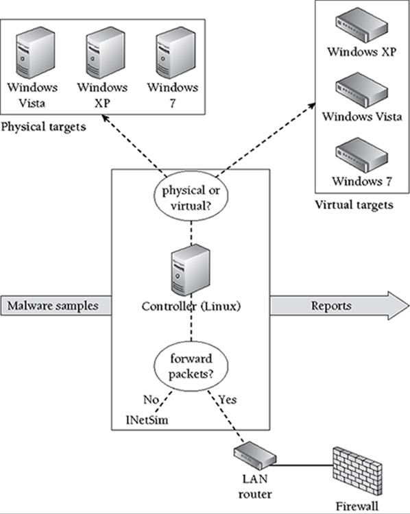
If you don’t plan on using physical targets, then it’s possible to create a lab based on a single computer or laptop. We highly recommend using Linux as the controller’s operating system, but that is not a requirement. You could also create a portable, personal lab on a laptop running Windows or Mac OS X. However, because we can’t provide instructions on every possible configuration, we’ll use the setup in Figure 7-1 as a general reference in this chapter, and we’ll simply point out where you’ll need to make adjustments if your lab differs in a major way.
The network in the sample diagram is contained on a single LAN because that’s what most people will use. Although it’s not shown in Figure 7-1, we’re assuming the firewall has an external IP address that faces the Internet. If you have access to a larger network or multiple external IP addresses from your ISP, then you could assign each target its own routable IP.
Before you begin setting up a lab, keep in mind that setting up a safe environment is very important, as you do not want to compromise your host or controller system. Virtual machines share a lot of resources with the host computer and can quickly become a security risk if you take them for granted. Here are a few pointers for preventing malware from escaping the isolated environment to which it should be confined:
· Make sure your virtualization software is up-to-date. Vulnerabilities in virtualization software can lead to malware infecting the host.
· Configure the firewall on your host to drop incoming packets from the targets.
· If you don’t want malicious code that you run in the target to reach the Internet, make sure you disable the virtual network card, use a host-only networking configuration, or contain traffic with simulation scripts (see Recipe 7-3).
· Disable shared folders between the host and target or make them read-only.
· Prevent the target from accessing any shared devices or removable media, such as USB drives that may be physically connected to your host.
· Do not customize your target system with any information that, if leaked by a trojan, could be used to identify you. For more information on staying anonymous, see Chapter 1.
The recipes in this chapter require a working knowledge of TCP/IP, Linux system administration, and Windows system administration. If you’re not familiar with installing and configuring virtual machines, see VMware’s guide (http://www.vmware.com/pdf/GuestOS_guide.pdf) or VirtualBox’s user manual (http://www.virtualbox.org/wiki/Downloads). You will also need a familiarity with forensic tools, as well as the ability to customize relatively simple Perl and Python scripts for your needs.
Networking
Configuring the network properly in your lab environment is a critical step for capturing and analyzing traffic that malware generates. Tackling this challenge requires an understanding of the different network settings that most virtualization products offer. Consult Table 7-1 for a summary of host-only, NAT/shared, and bridged networking modes.
Table 7-1: Virtual Machine Networking Modes
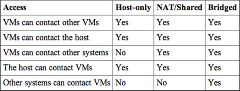
The three modes are defined as follows:
· Host-only mode: This creates a private LAN shared between the host and its VMs. VMs cannot communicate with external systems—which could be good or bad, depending on your goals. This is bad if you want to allow malware to contact real sites on the Internet, because it won’t work, but good if you want to contain traffic in your private sandbox environment.
· NAT/Shared mode: VMs can contact other machines on the LAN or Internet, but connections appear to come from the host’s IP address. Other machines cannot initiate incoming connections back to the VMs unless you configure port-forwarding on your host machine.
· Bridged mode: VMs share the host’s physical Ethernet adaptor, but they have their own IP address and MAC address. The VMs appear to be on the same local subnet as the host. This is the only configuration that allows other machines to make inbound connections to VMs. It is also the only mode that allows external machines, such as the router or firewall, to distinguish between traffic generated by the host and traffic generated by a VM on the host.
We recommend using bridged mode for your VMs and assigning them a dedicated IP address so that you can determine which VM is responsible for traffic that you capture. Of course, if you only have one VM and don’t expect incoming connections to your VM, then NAT/Shared mode will also be fine.
Recipe 7-1: Routing TCP/IP Connections in Your Lab
On your machine that functions as the controller per Figure 7-1, use ifconfig to determine its IP address. Then use ipconfig on your Windows targets to do the same thing. Verify that all machines are on the same subnet and make sure you can ping the controller from the Windows targets. For reference, Table 7-2 provides the relevant values for our test network, which are mentioned throughout the next few recipes.
Table 7-2: Values for the Test Network
|
Network Element |
Value |
|
Controller IP |
172.16.176.130 |
|
Windows target IP |
172.16.176.138 |
|
Netmask |
255.255.255.0 |
|
DNS |
172.16.176.2 |
|
Gateway |
172.16.176.2 |
Note If you’re short on hardware, you can use a Linux virtual machine to function as the controller. In this case, you’ll need at least two VMs—one running Windows (the target) and the other running Linux (the controller).
Now that you’ve verified network connectivity between your controller and the targets, you’ll need to make a few changes so that all traffic generated by programs on the target flows through the controller. We’ll discuss a few methods to do this, so you can evaluate the strengths and weaknesses, but we really only recommend using one method—the IP routing technique.
Redirecting DNS
If you happen to already know the DNS hostname of the server(s) contacted by the malware, you can modify the hosts file to direct connections to the controller’s IP. The hosts file is typically located in the %SYSTEMROOT%\config\drivers\etc directory and formatted like this:
# redirect DNS to the controller's IP
172.16.176.130 commandserver.com
The previous entry forces processes on the target machine to connect to your controller’s IP address after resolving commandserver.com with DNS. If you have a process on your controller waiting for incoming connections (we’ll get to that soon), you can start to log traffic and see what the malware would do upon successful connection to the realcommandserver.com server.
There are a few key flaws with this method. First of all, you won’t always preemptively know what hostname a sample contacts, and even if you did, adding entries to the hosts file each time is manual and tedious. Second, if malware resolves domains using the DNS_QUERY_NO_HOSTS_FILE flag to the DnsQuery API, then it will bypass your hosts file entries.
Another option is to create your own internal DNS server and configure it to return the controller’s IP for some, or all, hostnames that the target tries to resolve. Using this technique, you don’t have to manually edit the hosts file, but malware can still bypass your setup by not performing DNS lookups and contacting a system by its IP address. Malware might also ignore the DNS settings on your target machine and resolve hostnames using a public DNS server instead (for example, Google’s open DNS).
Redirecting IP with Routing
If you alter the network settings on your target, pointing its default gateway at your controller, then all traffic will hit your controller regardless of whether the malware contacts a system by DNS name or IP. You now have an important decision to make—do you want to log and forward packets to the real servers on the Internet or do you want to redirect the packets to a honeypot system or service simulation suite?
If you forward packets to the real servers, you can more accurately assess the malware’s behavior in the wild, but at the risk of tipping off the bad guys that you are analyzing malware and exposing your IP address to them (see Chapter 1 for tricks on how to stay anonymous). If you use a honeypot or simulation suite, you can create an entirely self-contained sandnet, but you won’t really be observing the malware in its native environment.
To route all of the target machine’s traffic through your controller, use the following steps:
1. On your controller running Linux, enable IP forwarding in the kernel by executing the following command as root:
$ sudo su
# echo 1 > /proc/sys/net/ipv4/ip_forward
2. On your controller, make sure the iptables default firewall policy allows the forwarding of packets, like this:
$ sudo iptables –P FORWARD ACCEPT
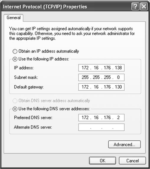
3. Back on your target, configure its network settings so that its default gateway points to the controller. You can do this in two ways. The first way involves typing the following command into cmd.exe:
C:\> route change 0.0.0.0 mask 0.0.0.0 172.16.176.130
The second way involves configuring the interface with the Windows GUI tool, as shown in Figure 7-2.
Figure 7-2: Routing Windows traffic through Your Linux controller
With this setup, you can be fairly confident that you can capture, redirect, or interact with any traffic generated on the Windows target machine. We said fairly confident because although we’ve never seen it in the wild, it’s possible for malware to reconfigure the default gateway of a target machine and send traffic around your controller. The ability to do this depends on the placement of your controller. The malware also needs to know the IP of the next-hop router that accepts and forwards traffic; however, that much it can learn from a simple trace route.
Recipe 7-2: Capturing and Analyzing Network Traffic
Now that all traffic sent to/from your targets flows through the controller, you should be able to start up a packet capture utility on the controller and watch packets go by in real time.
Note Besides the method of capturing packets that we describe in this recipe, here are a few other techniques you could use:
· Connect machines on your network to an old hub if you have one lying around, and use a promiscuous mode sniffer.
· Plug your sniffer into a switch or router that allows port mirroring.
· Connect your target machines to your controller via crossover cable.
Using Wireshark’s GUI
Wireshark1 is a network protocol analyzer that runs on Windows, Linux, Mac OS X, and various other platforms. Besides just capturing packets, Wireshark can perform deep inspection of hundreds of protocols, and export results as a binary pcap file, CSV, or XML. It also has powerful filtering capabilities. If Wireshark isn’t already installed on your controller, you can get it by running the following command:
$ sudo apt-get install wireshark
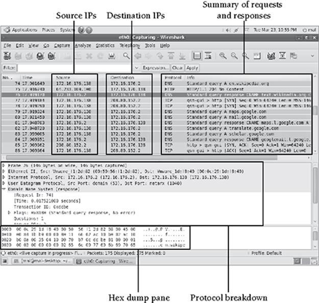
Figure 7-3 shows Wireshark’s GUI. You’ll notice that the source address for the DNS queries is 172.16.176.138—the target VM. The DNS server that replied to the queries is 172.16.176.2, per the configuration in the previous recipe. You can see that the target resolved hostnames in the wikipedia.org and google.com domains in order to communicate with those servers over HTTP.
Using tshark
If you prefer command-line tools (recommended for automated analysis), you can use tshark, which is the non-GUI version of Wireshark. You can install it like this:
$ sudo apt-get install tshark
The following command shows you how to capture packets on the eth0 interface, automatically quit after 60 seconds, and save packets to output.pcap.
$ sudo tshark –i eth0 –a duration:60 –w output.pcap
To read packets back using the same protocol dissectors as the GUI version of Wireshark, you can do this:
$ tshark –r output.pcap –V
Figure 7-3: Analyzing traffic with Wireshark
Using tcpdump
tcpdump2 doesn’t include extensive protocol analyzers like Wireshark and tshark, but it has stood the test of time and provides reliable, powerful packet capture and read-back capabilities. If you need to install it, use the following command:
$ sudo apt-get install tcpdump
The following command shows how to capture packets on the eth0 interface that are addressed to or from 172.16.172.138, and save all bytes in the packet (by setting the snaplen to 0) to output.pcap:
$ tcpdump –i eth0 –s 0 –w output.pcap host 172.16.172.138
The host keyword is one of many BPF-style filters that let you control exactly which packets to save in your file. For more information on BPF-style filters, type man tcpdump.
If you pass the –r flag to tcpdump, it will parse the saved packet capture file.
$ tcpdump –r output.pcap
We recommend that you also pass the –n flag to prevent tcpdump from continuously doing DNS lookups, which can take a while. Of course, if you want to see the DNS names instead of IP addresses, don’t use the –n flag.
Using Snort IDS
You can install the Snort3 IDS on your controller to alert on any suspicious traffic sent to or from your target machines while the malware is running. If you’ve got an IDS running in production, this will give you a good idea of what type of alerts you’ll see if the same or similar malware exists on the corporate network. The following commands create a simple Snort setup with the Emerging Threats4 signatures on your controller:
$ sudo apt-get install snort
$ sudo wget –P /etc/snort/rules \
http://www.emergingthreats.net/rules/emerging-all.rules
$ sudo echo 'include $RULE_PATH/emerging-all.rules' >> \
/etc/snort/snort.conf
$ sudo /etc/init.d/snort start
If you want to check if everything succeeded or see what command-line parameters the startup script sends to Snort, then you can view it like this:
$ cat /proc/'pidof snort'/cmdline
/usr/sbin/snort –m 027 –D –d –l /var/log/snort –u snort –g snort –c \
/etc/snort/snort.conf –S HOME_NET=[172.16.176.0/24] –i eth0
Table 7-3 gives an explanation of the parameters.
Table 7-3: Snort Parameters
|
Parameter |
Description |
|
-m 027 |
A umask for file creation |
|
-D |
Tells Snort to run in Daemon (i.e. background) mode |
|
-d |
Tells Snort to dump the application layer data in packets |
|
-l |
Tells Snort the top-level directory for storing logs |
|
-u and –g |
Tells Snort the user and group to run as |
|
-c |
Specifies the configuration file to use |
|
-S |
Sets the HOME_NET variable in the configuration file |
|
-i |
Specifies the interface on which to capture packets |
Based on that information, you can always look in /var/log/snort for the log files. By default, you’ll have a file named “alert” that contains essential information about packets that triggered IDS signatures. You’ll also have a file named tcpdump.log.XX (where XX is a unique number based on the time you start Snort) that contains a tcpdump-formatted copy of the packet(s) that triggered the signature.
You can visit the Snort project’s home page for additional documentation and tutorials. Some of the ideas you might consider implementing into your lab environment are:
· Enabling and disabling signatures or entire rulesets as desired
· Configuring oinkmaster5 for keeping signatures updated
· Compiling Snort using the --with-mysql flags to write logs and alerts to a MySQL database. Then you can view and analyze alerts via web interface by installing BASE.6
· Configuring the pre-processors and different options in snort.conf
1 http://www.wireshark.org/
2 http://www.tcpdump.org/
3 http://www.snort.org/start/documentation
4 http://www.emergingthreats.net/index.php
5 http://oinkmaster.sourceforge.net/
6 http://base.secureideas.net/
Recipe 7-3: Simulating the Internet with INetSim
It’s not a good idea to indiscriminately forward all traffic that reaches your controller to the intended servers on the Internet. In some cases, the servers may be unavailable, but you’ll still want to log the traffic generated by the malware to understand its behavior. This way, you can build IDS signatures and get enough information to search through firewall or web proxy logs to determine if any other machines on your network are infected. In these situations, you need to start up a process on your controller that can listen for, accept, and log incoming packets destined for any TCP and UDP ports.
The INetSim7 package by Thomas Hungenberg and Matthias Eckert not only handles logging, but it simulates various services that malware frequently expects to interact with. From the project’s feature page, it supports HTTP/HTTPS, SMTP/SMTPS, POP3/POP3S, DNS, FTP/FTPS, TFTP, IRC, and NTP; several small services such as Time and Echo; and dummy TCP/UDP services that handle connections directed at unknown or arbitrary ports. You can configure INetSim to respond to HTTP/HTTPS requests in fake mode and return default files based on extensions (for example, the same executable even if malware requests a.exe or b.exe) or you can use it in real mode and place the files you want to return in INetSim’s webroot directory.
To install INetSim on the controller in your lab (as shown in Figure 7-1), take the following steps:
1. Review the project’s requirements page and install any dependencies that you don’t already have. With a Debian/Ubuntu-based Linux, you can use the following commands (OpenSSL is not a documented requirement, but you’ll need it to create an SSL certificate).
$ sudo apt-get install perl \
perl-base \
perl-modules \
libnet-server-perl \
libnet-dns-perl \
libipc-shareable-perl \
libdigest-sha1-perl \
libio-socket-ssl-perl \
libiptables-ipv4-ipqueue-perl \
openssl
2. Download, extract, and move the INetSim files to the desired location on your Linux machine’s file system:
$ wget http://www.inetsim.org/downloads/inetsim-1.2.tar.gz
$ tar -xvzf inetsim-1.2.tar.gz
$ mv inetsim-1.2 /data
3. Add a group named inetsim to your controller:
$ sudo groupadd inetsim
4. Run the setup script, which creates default SSL keys and certificates for the HTTPS, POP3S, FTPS, and SMTPS services.
$ cd /data/inetsim-1.2
$ ./setup.sh
5. Change any preferences in the conf/inetsim.conf file to suit your needs. This is where you configure services to simulate, IP addresses for the services to bind to, IP addresses to return for DNS queries, and whether or not you want to enable redirection. When you enable redirection, INetSim creates all of the necessary iptables rules and redirects all connections going through the controller at the appropriate service.
6. Change the service_bind_address value to the IP address of your controller system that is running INetSim.
#########################################
# service_bind_address
#
# IP address to bind services to
#
# Syntax: service_bind_address <IP address>
#
# Default: 127.0.0.1
#
service_bind_address 172.16.176.130
7. Change the redirect_enabled value to yes.
#########################################
# redirect_enabled
#
# Turn connection redirection on or off.
#
# Syntax: redirect_enabled [yes|no]
#
# Default: no
#
redirect_enabled yes
8. Add any ports that should not be redirected to the redirect_exclude_port value. At a minimum, you should enter TCP port 22, so you can still reach your controller via SSH.
#########################################
# redirect_exclude_port
#
# Connections to <service_bind_address> on this port
# are not redirected
#
# Syntax: redirect_exclude_port <protocol:port>
#
# Default: none
#
redirect_exclude_port tcp:22
9. Launch the INetSim main program. If you plan to run INetSim as a daemon, you can find a startup script in the contrib directory.
$ sudo ./inetsim
INetSim 1.2 (2010-04-25) by Matthias Eckert & Thomas Hungenberg
Using log directory: /data/inetsim-1.2/log/
Using data directory: /data/inetsim-1.2/data/
Using report directory: /data/inetsim-1.2/report/
Using configuration file: /data/inetsim-1.2/conf/inetsim.conf
Parsing configuration file.
Configuration file parsed successfully.
=== INetSim main process started (PID 2673) ===
Session ID: 2673
Listening on: 172.16.176.130
Real Date/Time: Wed May 12 16:40:36 2010
Fake Date/Time: Wed May 12 16:40:36 2010 (Delta: 0 seconds)
Forking services...
* dns 53/udp/tcp - started (PID 2676)
* http 80/tcp - started (PID 2677)
* https 443/tcp - started (PID 2678)
* tftp 69/udp - started (PID 2685)
* smtp 25/tcp - started (PID 2679)
* irc 6667/tcp - started (PID 2686)
* smtps 465/tcp - started (PID 2680)
[REMOVED]
* redirect - started (PID 2705)
done.
Simulation running.
When you execute malware on the Windows target, INetSim records logs of the activity. The following data from the logs/service.log file shows the HTTP request and user agent sent by a malware sample. The log also shows that the INetSim server replied to the request with the default sample.html, because it is currently operating in fake mode. If you want INetSim to respond with specific HTML content, you could configure real mode in inetsim.conf. Additionally, if the malware sends e-mails, you can find them in MBOX format in the data/smtp/smtp.mbox file—it’s as simple as that.
[2010-05-12 17:05:37] [3012] [http 80/tcp 3088] \
[172.16.176.138:1239] connect
[2010-05-12 17:05:37] [3012] [http 80/tcp 3087] \
[172.16.176.138:1238] recv: User-Agent: \
Mozilla/4.0 (compatible; MSIE 6.0; Windows NT 5.1; \
SV1; .NET CLR 2.0.50727; .NET CLR 3.0.4506.2152; \
.NET CLR 3.5.30729)ver52
[2010-05-12 17:05:37] [3012] [http 80/tcp 3087] \
[172.16.176.138:1238] recv: Host: aahydrogen.com
[2010-05-12 17:05:37] [3012] [http 80/tcp 3087] \
[172.16.176.138:1238] info: Request URL: \
http://aahydrogen.com/ufwnltbz/wzdcjrp.php?adv=adv448
[2010-05-12 17:05:37] [3012] [http 80/tcp 3088] \
[172.16.176.138:1239] recv: GET /ufwnltbz/hypwhc.php?adv=adv448 \
HTTP/1.1
[2010-05-12 17:05:37] [3012] [http 80/tcp 3088] \
[172.16.176.138:1239] recv: User-Agent: \
Mozilla/4.0 (compatible; MSIE 6.0; Windows NT 5.1; SV1; \
.NET CLR 2.0.50727; .NET CLR 3.0.4506.2152; \
.NET CLR 3.5.30729)ver52
[2010-05-12 17:05:37] [3012] [http 80/tcp 3088] \
[172.16.176.138:1239] recv: Host: aahydrogen.com
[2010-05-12 17:05:37] [3012] [http 80/tcp 3088] \
[172.16.176.138:1239] info: Request URL: \
http://aahydrogen.com/ufwnltbz/hypwhc.php?adv=adv448
[2010-05-12 17:05:37] [3012] [http 80/tcp 3087] \
[172.16.176.138:1238] send: 200 OK
[2010-05-12 17:05:37] [3012] [http 80/tcp 3087] \
[172.16.176.138:1238] send: Server: INetSim HTTP Server
[2010-05-12 17:05:37] [3012] [http 80/tcp 3087] \
[172.16.176.138:1238] send: Connection: Close
[2010-05-12 17:05:37] [3012] [http 80/tcp 3087] \
[172.16.176.138:1238] send: Content-Length: 258
[2010-05-12 17:05:37] [3012] [http 80/tcp 3087] \
[172.16.176.138:1238] send: Content-Type: text/html
[2010-05-12 17:05:37] [3012] [http 80/tcp 3087] \
[172.16.176.138:1238] send: Date: Wed, 12 May 2010 21:05:37 GMT
[2010-05-12 17:05:37] [3012] [http 80/tcp 3087] \
[172.16.176.138:1238] info: Sending file: \
/data/inetsim-1.2/data/http/fakefiles/sample.html
[2010-05-12 17:05:37] [3012] [http 80/tcp 3087] \
[172.16.176.138:1238] stat: 1 method=GET \
url=http://aahydrogen.com/ufwnltbz/wzdcjrp.php?adv=adv448 \
sent=/data/inetsim-1.2/data/http/fakefiles/sample.html \
postdata=
[2010-05-12 17:05:37] [3012] [http 80/tcp 3087] \
[172.16.176.138:1238] disconnect
In Chapter 8, we’ll show you how to leverage INetSim in an automated environment. By setting the --log-dir and --report-dir parameters when starting InetSim, you can save log files to a different directory each time you run a malware sample.
7 http://www.inetsim.org/index.html
Recipe 7-4: Manipulating HTTP/HTTPS with Burp Suite
So far in this chapter, you’ve learned how to configure a controller running Linux that captures and forwards packets generated by malware on the target machines. You’ve also learned how to create a flexible, self-contained simulated network. Suppose, now, that you needed a hybrid setup—one that captures packets and forwards requests to the real command and control servers on the Internet, but gives you the ability to dynamically manipulate requests and responses. This sounds like a classic man-in-the-middle attack, which in fact it is, but you’re not using it for attack purposes; you’re using it as a mechanism to control what the malware sends and receives in order to elicit or observe specific behaviors. Consider the following theoretical scenarios:
· A malware sample uses the infected machine’s volume serial number (see GetVolumeInformation API) to uniquely identify itself when contacting the command server. The server responds with an updated executable the first time it sees each serial number. You’ve previously run the malware on your VM, then reverted, and now you need to execute it a second time. You want to trick the server into thinking this is the first time by changing the serial number that the malware sends in the HTTP request.
· A malware sample uses a web-based instant messenger (IM) or Internet relay chat (IRC) service as its command and control protocol. Once the malware logs into the service, it begins to issue commands, such as listpeers and nextdns, to which one or more bots respond. However, via strings analysis of the malware, you see a blinktwice command. No matter how many times you run the malware sample, it never sends the blinktwice command. You want to find out what response the command invokes, and how the malware behaves after receiving the response, by injecting the blinktwice command into the malware’s active IM/IRC connection.
You’ll need to set up a proxy on your controller so that it can intercept the target’s outgoing HTTP requests. This gives you a chance to modify, drop, or allow the requests to pass. Proxies such as SPIKE Proxy8 by Immunity, Paros Proxy,9 and ProxyStrike10 were written for fuzzing and finding vulnerabilities in web applications, but you can use them for malware analysis as well. In this recipe, we’ll show you how to use Burp Suite11 by PortSwigger.
1. Configure routing between your Windows targets and your controller as outlined in Recipe 7-1.
2. Download the most recent version of PortSwigger Burp Suite. Burp supports a feature called invisible proxying, which is critical for being able to capture and manipulate HTTP/HTTPS requests from non–proxy-aware clients (many malware samples are not proxy aware).12 There’s no installation for Burp, but you’ll need a recent Java Runtime Environment (JRE).
$ unzip burpsuite_v1.3.03.zip
$ cd burpsuite_v1.3.03
$ sudo apt-get install default-jre
$ java –jar burpsuite_v1.3.03.jar
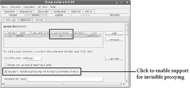
3. You should see the Burp GUI. Click proxy⇒ options and edit the configuration for the proxy listener, as shown in Figure 7-4. You’ll specifically want to unselect the “listen on loopback interface only” option and select the “support invisible proxying for non-proxy-aware clients” option. Then click “update.”
4. Click the proxy ⇒ intercept tab and then the button labeled “intercept is off” to toggle it on.
Figure 7-4: Enabling invisible proxy support with Burp
5. Create iptables rules that redirect any HTTP (port 80) or HTTPS (port 443) connections flowing through your controller to the Burp process listening on port 8080. The commands should look like this:
$ sudo iptables –t nat –A PREROUTING –p tcp –-dport 80 \
–j REDIRECT –-to-ports 8080
$ sudo iptables –t nat –A PREROUTING –p tcp –-dport 443 \
–j REDIRECT –-to-ports 8080
Now you’re done with the setup and can proceed with executing malware on the target. As soon as it issues an HTTP or HTTPS request, you’ll get the chance to modify the headers, URL parameters, and any POST payload before forwarding it to the real server. Of course, you can drop requests as well, which prevents them from being sent. In you drop requests, the malware will just think the server is temporarily unreachable and it will probably try the request again later. You can modify anything you see in the raw view (see Figure 7-5) or switch to hex mode and modify individual bytes.
Figure 7-5: Intercepting requests and responses
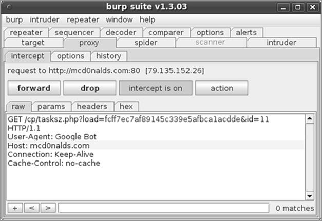
The technique described in this recipe is non-invasive to the malware. The sample has no idea that you’re manipulating its requests and/or responses. Furthermore, it’s non-invasive to the entire system on which the malware runs because your proxy application is actually on the controller machine. Because Burp supports invisible proxying, it works against nearly all malware samples that communicate over HTTP or HTTPS, whether they use the WinINet API, Winsock API, Urlmon API, and even if they initiate connections via kernel drivers.
8 http://www.immunitysec.com/resources-freesoftware.shtml
9 http://www.parosproxy.org/
10 http://code.google.com/p/proxystrike/
11 http://portswigger.net/suite/download.html
12 http://blog.portswigger.net/2008/11/mobp-invisible-proxying.html
Physical Targets
If you need a lab for malware analysis that isn’t based on emulation or virtualization, then you can consider using Truman, Deep Freeze, or FOG. Each of these solutions works differently, but they all provide a way to execute malware on a physical machine without needing to manually reformat the drive and/or reinstall Windows after analyzing each sample. The benefit to using physical machines is that malware can run in its native environment, without emulators, hypervisors, and other potentially behavior-modifying layers of abstraction.
Recipe 7-5: Using Joe Stewart’s Truman
In 2006, Joe Stewart released Truman13 (The Reusable Unknown Malware Analysis Net) under a GPL license. Using this system requires a pair of physical computers—one for the Truman server (typically running Linux) and one for the malware client (running Windows)—that are connected over a high-speed Ethernet cable. The Truman server has many duties, one of which is making a dd-style image of the client’s disk after it executes each sample. The server downloads the image for analysis and then re-images the client with the baseline/clean image before the next analysis. Truman’s ability to re-image the machine is based on a PXE boot setup.
The Truman server includes a set of Perl scripts that simulate Internet services such as SMTP, FTP, and IRC. Therefore, it can interact with the malware to a certain extent. Truman includes primitive memory analysis capabilities—the client dumps physical memory to a file on disk (using dd.exe if=\\.\PhysicalMemory of=c:\memdump.img) before the server images the drive. This gives the server access to the memory dump. Joe’s pmodump.pl script can extract an unpacked copy of the malware from the memory dump or, of course, nowadays you can automate Volatility into the analysis.
For more information on Truman, see the NSMWiki’s Truman Overview14 or the Truman Installation Notes.15 In his 2009 SANSFIRE presentation,16 Jim Clausing explained how he updated Truman to support the following features:
· Memory analysis with Volatility
· Registry change detection with regdiff.pl and dumphive
· Registry analysis with RegRipper
· Packer identification with a custom Python script
· Network traffic analysis with tshark, tcpdump, tcpdstat, and ipaudit
· NTFS ADS streams with getfattr
· Fuzzy hashes of files with ssdeep
13 http://www.secureworks.com/research/tools/truman.html
14 http://nsmwiki.org/Truman_Overview
15 http://nsmwiki.org/Truman_Installation_Notes
16 http://handlers.dshield.org/jclausing/grem_gold/
Recipe 7-6: Preserving Physical Systems with Deep Freeze
Deep Freeze17 by Faronics is a solution that prevents permanent changes to a computer’s file system. It is supported on most Mac OS X and Windows platforms and is additionally available for some Linux distributions. The product is available in two editions:
· Standard: This is more like a personal license for a single computer.
· Enterprise: Allows you to remotely access, configure, manage, and update multiple Deep Freeze clients throughout a network.
Deep Freeze is popular in schools, public libraries, and other locations where many different people are likely to use the same computer and change the settings (or get it infected with malware). It is not marketed as a malware analysis solution. However, because it can prevent both intentional and unintentional changes, Deep Freeze is a great way to analyze malware without lasting effects or fear of permanently damaging your system.
Installing Deep Freeze
Deep Freeze can be evaluated free for 30 days with all of its features, but you will have to purchase it for use beyond that period. For this recipe, we downloaded an evaluation of Deep Freeze Standard Edition for Windows. The download link is a Zip file that has the Deep Freeze setup executable inside of it (Faronics_DFS.exe). Unzip this file and run it to commence the Deep Freeze installation.
During the installation process, you must choose which drives you want to be “Frozen” or protected by Deep Freeze. This screen looks like Figure 7-6.
Figure 7-6: Selecting which drives to protect
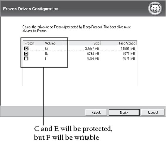
If you want to save files while Deep Freeze is running, you must designate an unprotected drive (notice how we didn’t select the F drive). Alternately, you can save files to external media such as a USB drive or network shares.
Once you have completed the installation, your computer will reboot. You’ll be prompted to create a password for making changes to Deep Freeze in the future or for uninstalling it.
Managing Deep Freeze States
Deep Freeze places an icon in the system tray that indicates whether the computer is currently in a Frozen or Thawed state. In a Frozen state, all the drives you selected during installation are protected from changes. In a Thawed state, the drives are not protected. To change states, you must know the password set at installation and the computer must be rebooted.
Figure 7-7 shows how the icon in the system tray appears. The left figure shows the Frozen state and the right shows the Thawed state.
Figure 7-7: The small red “x” in the bottom right corner of the Deep Freeze icon indicates a Thawed state.

To make changes to Deep Freeze, you need to hold down the Shift key while double-clicking the system tray icon. Once logged in, you will see the console shown in Figure 7-8.
Figure 7-8: Deep Freeze administration console
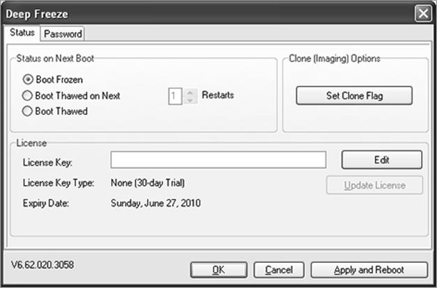
In this administrative console, you can choose to boot the system in a Thawed state for an indefinite period of time or until the system reboots a specified number of times. The Thawed state is useful for installing patches or making changes to the system that you want to persist after further reboots. The Enterprise Edition of Deep Freeze has many other configuration options and allows you to specify ThawedSpace, which is space set aside on your hard drive to which you can make changes. The Enterprise Edition also gives you a way to centrally manage Deep Freeze clients on the network, which is great for automation purposes. For example, you can remotely force machines to reboot into a Thawed or Frozen state using the command-line task scheduler.
Pros and Cons for Malware Analysis
As long as Deep Freeze is in a Frozen state, you can execute malware or browse malicious websites without fear of permanently infecting or damaging your system. You can manually delete files or make any changes to test. Simply reboot the machine to find that deleted files have returned and all changes have been reverted.
If the malware attempts to detect virtual environments, you’re all set because you’re running it on a physical system. However, Deep Freeze is not without caveats. As described on a public forum,18 Deep Freeze prevents programs from gaining certain privileges such as SeDebugPrivilege or SeSystemtimePrivilege. If an attacker exploits a weakness in the Windows kernel or Deep Freeze software and gains these privileges, he can make permanent changes to the system. A tool called Deep Unfreezer19 demonstrated such an attack, but Deep Freeze has since strengthened its security model so the attack no longer works.
Note Deep Freeze is just one of the available tools for restoring a system’s state. Lenny Zeltser wrote an article on the ISC blog presenting a few others, such as Windows SteadyState, Returnil, and CoreRestore, which you can read about here: http://isc.sans.edu/diary.html?storyid=4147.
17 http://www.faronics.com/en/default.aspx
18 https://forum.hackinthebox.org/viewtopic.php?f=1&t=506&start=20
19 http://usuarios.arnet.com.ar/fliamarconato/pages/edeepunfreezer.html
Recipe 7-7: Cloning and Imaging Disks with FOG
FOG20 is a free and open-source computer cloning and imaging solution created by Chuck Syperski and Jian Zhang. Although it’s not designed specifically for malware analysis, you can leverage it to restore installations of Windows XP, Vista, or Windows 7 onto physical computers after using them in your lab. In fact, Joebox, which is described in Chapter 4, utilizes FOG for such purposes. FOG runs on Linux and includes a web-based management interface. It uses PXE boot and Partimage (open source disk backup software) for some of the heavy lifting.
This recipe walks you through the basic steps of using FOG. For the nitty-gritty details, however, you need to refer to the FOG user guide,21 which is over 50 pages and will likely cover anything we, the authors, don’t cover here. To begin, you’ll need at least two physical machines on the same subnet.
Installing FOG
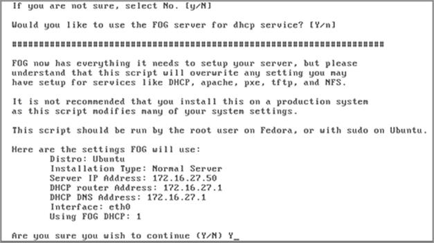
On your first physical machine (the one on which you will run FOG), install a Linux-based OS. The user guide includes tutorials specifically for Fedora, Ubuntu, and CentOS. If you’re just curious about how FOG works or don’t currently have the required hardware, you can download the pre-built VMware image. There may be a performance hit and you’ll still have to configure FOG with your network-specific settings such as router address, DNS address, and DHCP server. Most of that is self-explanatory and there’s a setup script that guides you through the process. Figure 7-9 shows a summary of the information you need to provide.
Figure 7-9: Setting up FOG requires basic network settings
Adding an Image Definition
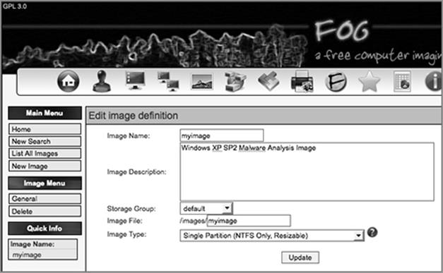
Before you begin cloning and restoring machines, you need to create an image definition. An image definition describes the type of image that you’ll be working with (e.g., single NTFS partition, multiple partitions on a single disk, multiple partitions on all disks, and so on). You can add an image definition by pointing a web browser to your FOG server’s IP address and selecting Image Management ⇒ New Image. As shown in Figure 7-10, this recipe chooses the name myimage, uses the default storage group, and selects a single NTFS partition.
Note Selecting a resizable, single partition greatly enhances the speed of the imaging process. If a 100GB partition contains only 8GB of data, only 8GB of data needs to be transferred. The downside is that the single NTFS partition doesn’t contain the MBR (Master Boot Record). Thus, infections by MBR rootkits could persist even after you image a computer with the clean NTFS partition. To protect against persistent MBR infections, make sure you choose an image type that preserves the original system’s MBR, even if the imaging process takes longer.
The first image definition you create will receive image ID #1. In the future, you can add as many images as you want—one for Windows XP SP1 with Adobe Reader 8.1, one for Windows Vista with Adobe Reader 9.1, one for Windows 7, and so on.
Figure 7-10: Adding an image definition through the web interface
Client Preparation
Install Windows XP, Vista, or 7 on your FOG client(s). At this time, you must also install any software that you want to use for analyzing malware or logging malware behaviors. Keep in mind that anything you add is subject to detection by the malware, which may alert it to the fact that it’s running in a monitored environment.
Enable PXE Boot in the BIOS
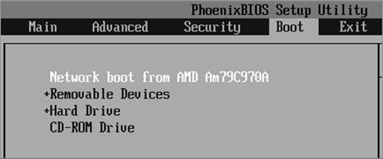
For each FOG client, you’ll need to enable network boot (i.e. PXE boot) in the BIOS. Depending on your hardware, the exact setting will have a different name and likely be in a different place, but Figure 7-11 shows the basic idea—make sure network boot is first in the boot order.
Figure 7-11: Enabling network boot in the BIOS
Host Registration and Imaging
When you save changes and exit the BIOS, the FOG client obtains an IP address from the DHCP server. If you didn’t configure the FOG server to function as a DHCP server (or reconfigure an existing DHCP server on your subnet to handle PXE boot), then this step will fail—see the user guide. If it succeeded, you’ll see a boot screen on the FOG client that looks likeFigure 7-12.
Figure 7-12: Registering a client with the FOG server after PXE boot
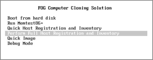
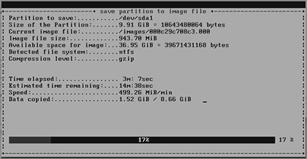
Choose the “full host registration and inventory” option. This uploads details about the FOG client’s MAC address, hostname, and hardware to the FOG server. You are prompted to associate the FOG client with an existing image ID. In this case, choose image ID #1. The FOG client’s disk image (a single NTFS partition in this case) is, then, uploaded to the FOG server and associated with image ID #1. You can observe the progress on the FOG client (see Figure 7-13) and in the Active Tasks area of the FOG’s server’s HTTP site.
Figure 7-13: Transferring the client’s disk image
Cloning and Restoring
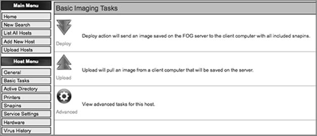
Now the fun begins. You can execute malware on your FOG client and engage any dynamic and/or static analysis techniques without worrying about infecting the computer. When you’re done analyzing a sample, you can deploy your clean image back to the FOG client and restore it to the original state. Or, if you have prepared other images, you could deploy a different version of Windows to your FOG client and determine how that influences the malware’s behavior. Figure 7-14 shows the basic imaging tasks that let you restore a FOG client (deploy) or pull an image from a FOG client (upload).
Figure 7-14: Basic imaging tasks menu in the web interface
You can manage thousands of physical machines from the same FOG server and if your load gets too high, you can split up responsibilities (such as HTTP server, DHCP server, imaging) across multiple FOG servers.
20 http://www.fogproject.org/
21 http://www.fogproject.org/wiki/index.php?title=FOGUserGuide
Recipe 7-8: Automating FOG Tasks with the MySQL Database
Any of the tasks that you typically schedule (such as deployment or upload of an image to a FOG client) via the HTTP interface, you can also automate by inserting data into the MySQL database via Python (or another scripting language).
The goal of the following commands is to find a physical computer currently running XP and schedule it to be restored. You’ll also see how to schedule the same computer to be restored with a different operating system. Follow these steps:
1. Log into MySQL and select the FOG database.
root@FOGServer:~# mysql –u root -p
Welcome to the MySQL monitor. Commands end with ; or \g.
Your MySQL connection id is 3945
Server version: 5.0.51a-3ubuntu5.4 (Ubuntu)
Type 'help;' or '\h' for help. Type '\c' to clear the buffer.
mysql> use fog
Database changed
2. Determine the operating system ID for Windows 2000/XP:
mysql> SELECT * FROM supportedOS;
+------+-----------------+---------+
| osID | osName | osValue |
+------+-----------------+---------+
| 1 | Windows 2000/XP | 1 |
| 2 | Windows Vista | 2 |
| 3 | Other | 99 |
| 4 | Windows 98 | 3 |
| 5 | Windows (other) | 4 |
| 6 | Linux | 50 |
| 7 | Windows 7 | 5 |
+------+-----------------+---------+
7 rows in set (0.02 sec)
3. Find a FOG client running Windows 2000/XP by comparing the supportedOS.osValue column with the hosts.hostOS column.
mysql> SELECT hostID,hostName,hostImage FROM hosts WHERE hostOS=1;
+--------+----------+--------------+-----------+
| hostID | hostName | hostIP | hostImage |
+--------+----------+--------------+-----------+
| 2 | mytarget | 172.16.27.65 | 1 |
+--------+----------+--------------+-----------+
1 row in set (0.00 sec)
There is currently only one physical machine running Windows 2000/XP and its hostID value is 2.
4. Now you can schedule a task for the FOG client identified by its hostID. The following command queues an action with taskType value of D, which stands for Deploy. In other words, now that you’ve made this entry, the FOG client is restored with its original Windows 2000/XP image the next time it reboots.
mysql> INSERT INTO tasks
VALUES (NULL, /* taskID - auto increments */
'', /* taskName */
NOW(), /* taskCreateTime */
NOW(), /* taskCheckIn */
2, /* taskHostID - from fog.hosts table */
0, /* taskState - 0:queued, 1:progress, 2:done */
'', /* taskCreateBy */
0, /* taskForce - false */
0, /* taskScheduledStartTime - immediate */
'D', /* taskType - 'D':deploy, 'U':upload, etc */
0, /* taskPCT */
'', /* taskBPM */
'', /* taskTimeElapsed */
'', /* taskTimeRemaining */
'', /* taskDataCopied */
'', /* taskPercentText */
'', /* taskDataTotal */
1, /* taskNFSGroupID */
1, /* taskNFSMemberID */
0, /* taskNFSFailures */
0 /* taskLastMemberID */
);
Query OK, 1 row affected (0.07 sec)
4. To deploy a different image to the FOG client, first add some additional images and then list their imageIDs.
mysql> SELECT imageID,imageName,imageDesc FROM images;
+---------+------------+---------------------------------------+
| imageID | imageName | imageDesc |
+---------+------------+---------------------------------------+
| 1 | myimage | Windows XP SP2 Malware Analysis Image |
| 2 | vistaimage | Windows Vista - Base Install |
| 3 | winseven | Windows 7 - Debugging Tools |
+---------+------------+---------------------------------------+
3 rows in set (0.00 sec)
5. Take the imageID value for the image you want to use, and set the hosts.hostImage column, like this:
mysql> UPDATE hosts SET hostImage=3,hostOS=5 WHERE hostID=2;
Query OK, 1 row affected (0.01 sec)
Rows matched: 1 Changed: 1 Warnings: 0
The FOG client is imaged with Windows 7 the next time it reboots.
The FOG client service component can fulfill the missing piece for automated malware analysis. The client service runs on the FOG client and it periodically (at a user-configured time interval) checks to see if any tasks are scheduled with the FOG server. The client service can change the client’s hostname, reboot or shut down the client machine, or log off the current user. You can write your own snap-ins in C# and integrate them into the client service for handling pre- and post-analysis actions.
All materials on the site are licensed Creative Commons Attribution-Sharealike 3.0 Unported CC BY-SA 3.0 & GNU Free Documentation License (GFDL)
If you are the copyright holder of any material contained on our site and intend to remove it, please contact our site administrator for approval.
© 2016-2026 All site design rights belong to S.Y.A.