AutoCAD Platform Customization: User Interface and Beyond (2014)
Chapter 2. Working with Nongraphical Objects
Nongraphical objects, also known as named objects, are objects that are stored in a drawing but that are not visually part of your design in model space or paper space. They do affect the appearance of the linework and annotations visible in a drawing, control which objects are displayed, organize plot settings for outputting a layout, and much more. The nongraphical objects you might have to work with in a drawing include the following:
◆ Blocks
◆ Plot styles
◆ Detail view styles
◆ Render presets
◆ Dimension styles
◆ Section view styles
◆ Layers
◆ Table styles
◆ Layouts
◆ Text styles
◆ Linetypes
◆ User coordinate systems (UCSs)
◆ Materials
◆ Visual styles
◆ Multileader styles
◆ Viewports
◆ Multiline styles
◆ Views
Chances are, you’ve worked with many of these nongraphical objects and are already familiar with them. This chapter covers creating and managing the four most commonly used nongraphical objects: layers, text styles, dimension styles, and table styles. This chapter also explores the other nongraphical objects from the list and how you can work with them.
Standardizing the Names of Nongraphical Objects
The name of a nongraphical object is important to you and others who work in the drawings based on your company’s CAD standards. Just as when you are naming projects and fi les, you should create meaningful names for your nongraphical objects so that you can quickly identify which object you need to work with and when. At a minimum, you will want to establish and use a naming standard for the layers in your drawing, since you can end up with dozens or even hundreds of different layers being used in a single drawing.
Establishing and following a naming standard helps ensure that the correct objects in a drawing are organized on the appropriate layers; as a result, they appear correctly in the output that you
eventually generate from a drawing. Utilizing standard names also makes it easy to identify which layers are used internally and allows your clients to effi ciently use them with your drawings.
As with project- and fi le-naming standards, you can defi ne your own naming standards or use those established by an industry body such as the American Institute of Architects (www.aia.org), National Institute of Building Sciences (www.nibs.org), Royal Institute of British Architects (www.architecture.com), or American National Standards Institute (www.ansi.org).
Layer Names
Layer names should be descriptive to give you control over the visibility and appearance of the objects in a drawing onscreen and during output. As part of a layer name, consider including the discipline, object classifi cation/type, and the status of the objects on that layer. It is not uncommon to use layers to distinguish objects that are temporary construction lines from those of your design. Layers can also be used to distinguish walls that should be demolished from those that are to be constructed.
A basic layer name might contain the following information:
Discipline Often, a single letter represents the main discipline that will use the layer—for example, A for Architecture, C for Civil, M for Mechanical, or S for Structural.
Secondary Discipline Often, a single letter helps to provide an additional level of classifi cation for the layer based on the designated main discipline—for example, S for site, D for demolition, or I for interior.
Major Classifi cation Often, a grouping of three or four letters are used to identify the view or main purpose of the contents on the layer—for example, -ANNO for annotation, -ELEV for elevations, -DETL for details, and -PLAN for plans.
Minor Classifi cation Level 1 Often, a grouping of three or four letters is used to further refi ne and specify the types of objects that might be on a layer—for example, -DIMS for
dimensions, -FURN for furniture, -NOTE for notes, -OBJT for generic objects, and -PATT for hatches or fi lls. The minor classifi cation might also contain a combination of alphabetic and numeric values to uniquely identify a layer within a drawing so that you can have more than one plan annotation layer—for example, -A001 for annotation layer 001 or -A020 for annotation layer 020.
Minor Classifi cation Level 2 Often, a grouping of three or four letters can be used to further refi ne the use of the layer and which objects should be placed on it—for example, -PRIM
for primary objects, -OPNG for opening, -PIPE for piping, and -EQPM for equipment.
Status Often, a single alphabetic or numeric value identifi es the status of the objects on the layer or associates a phase with the objects—for example, D for demolish, N for new, or 1 for phase 1.
Figure 2.1 shows a possible structure for a layer name.
Figure .:
A
I
P
L
A
N
F
U
R
N
P
A
N
L
N
Possible layer-
naming structure
Discipline
Major
Minor
Minor
Status
Classification
Classification
Classification
Secondary
Level 1
Level 2
Discipline
Other Object Names
Unlike layers, the other nongraphical objects in a drawing often do not use a rigid naming structure. In most cases, these names are driven individually by each company because, compared to layers, they do not have as great of an impact on the ability to output a drawing. When you name the nongraphical objects that are not layers in a drawing, follow these suggestions:
◆ Keep names short, about 31 characters, so that they fi t nicely into the list boxes and drop-down lists that are used by the dialog boxes and other areas of the Autodesk® AutoCAD®
user interface.
◆ Be descriptive in your names and use abbreviations whenever possible. For example, the name DR32-90L is much more descriptive than the name D1. A new drafter will have a better chance of remembering that the block named DR32-90L represents a door that opens to
the left and has an opening 32” wide.
◆ Append the height of the text or dimension scale, such as 1_4 for 1/4” height text or 96 for a scale of 1/8” = 1’-0”, to each of your text or dimension style names if you are not using annotation scaling. This will make it easier to identify the correct styles without having to open one of the style managers to see the current value.
◆ Be consistent and use as many of the layer descriptors as possible with your block names, annotation styles, and named views. Consider using -PLAN for plan views, -NOTE for text
styles that are used for general notes, or -SECT as part of a block name so that you know it should be used with section details. For example, if you want to create two new blocks that represent a single 2” pulley that can be mounted on a surface, you might want to use the
block names SP2M-PLAN and SP2M-SIDE for the plan and side views, respectively.
Renaming Nongraphical Objects
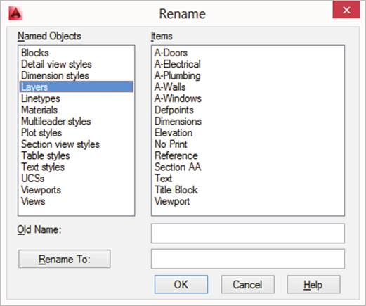
You can rename nongraphical objects using the dialog box that you used to originally create the object, or you can use the rename command. The rename command displays the Rename dialog
box. If you are updating your existing CAD standards or moving to a new set of standards, you can use the -rename command in a script fi le or custom program to automate in a single operation the process of renaming several nongraphical objects in the drawings that have already been created. I discuss scripts in Chapter 8, “Automating Repetitive Tasks.”
Use the following steps to rename a nongraphical object in an existing drawing:
1. Do one of the following:
◆ At the command prompt, enter rename and press Enter (Windows and Mac OS).
◆ Click Format menu ➢ Rename (Mac OS).
2. When the Rename dialog box (see Figure 2.2) opens, select the type of object you want to rename from the Named Objects list.
3. From the Items list, select the object you want to rename.
4. Do one of the following
◆ In the Rename To text box, enter the new name for the object and click Rename To
(Windows).
◆ Select the object a second time to display the in-place text editor, and enter the new
name for the object (Mac OS).
5. Repeat steps 2–5 for each object you want to rename.
6. Click OK when you have fi nished renaming objects.
Figure .:
Renaming
nongraphical
objects
Managing Object Properties with Layers
Objects in a drawing have a number of properties in common with each other: color, linetype, lineweight, and several others. These are often referred to as an object’s general properties. You can modify these properties individually using the Properties palette (Windows) or Properties Inspector (Mac OS) or let an object inherit values based on the layer in which it is placed.
I recommend allowing objects to inherit their properties from the layer in which they are placed; it is much easier to modify a single layer than it is to modify several thousands of objects. In addition, layers make it much simpler to control the visibility, locking, and plotting state of all related objects on a layer. An object’s general properties must be set to ByLayer to allow it to inherit the property values of the layer it is on. Setting an object’s property value directly overrides the layer’s property value, which could have undesired effects when plotting or printing a drawing.
Layers are commonly created using the layer command. As a rule of thumb, don’t allow
individual users to create their own layers in each drawing, as doing so can introduce the following:
◆ Errors against the established CAD standards; the wrong layer name or incorrect
property values
◆ Ineffi ciencies in your processes because of the amount of time it takes to defi ne each
layer that is needed
You can add all your commonly used layers to drawing template fi les so they are ready for use when the drawing is created. However, if a layer is not used it can inadvertently be purged from a drawing with the purge command. If a layer that was purged is needed later in the
project, that layer will need to be re-created manually, inserted as a block that contains the missing layers, or re-created using an automated process. One of the simplest solutions to restoring standard layers that were purged from a drawing is to maintain a drawing fi le that contains the same layers as those in your drawing template fi les. Then, you can insert the drawing fi le with the insert command; all previously purged layers that were part of your drawing template fi le are restored and the layers that exist in both drawings are ignored.
In addition to adding your layers to a drawing template, consider using the -layer command in a script fi le or custom program to create the layers you need in a drawing. This approach has two benefi ts: you can use the script or program to create the layers in your drawing template fi le, and you can use it to reset the properties of layers if someone changes their values to be different from your CAD standards.
Setting the Default Properties for New Objects
When new objects in a drawing are created, they take on not only the current layer, but also a number of other values that are typically set to the value ByLayer or 0.0000. You can adjust these properties in the General section of the Properties palette (Windows) or Properties Inspector (Mac OS) when no object is currently selected. You can also use the ribbon controls in AutoCAD on Windows. As an alternative, the system variables listed in Table 2.1 can be used to control the default property values assigned to new objects that are created with a command.
Table 2.1:
System variables used to set default property values
System Variable
Sets
cecolor
Color
celtscale
Linetype scale
celtype
Linetype
celweight
Lineweight
clayer
Current layer
cmaterial
Material
Table 2.1:
System variables used to set default property values (continued)
System Variable
Sets
cplotstyle
Plot style
elevation
Elevation in the Z direction
thickness
Object thickness
These system variables are helpful if you decide to create scripts or custom programs that create new objects or perform drawing setup tasks. I cover scripts in Chapter 8.
In most cases, you want to make sure that these variables are set to ByLayer or the equivalent value to make sure your new objects inherit the properties from the layer they are placed on.
You can use the setbylayer command to reset an object’s properties to ByLayer.
Creating and Managing Layers
You typically use the Layer Properties Manager (Windows) or Layers palette (Mac OS) to create new layers and edit existing ones in a drawing. When one of the interfaces is displayed, you click the Create New Layer (Windows) or New Layer (Mac OS) button and then set the properties in the Layers list for the new layer. Editing a layer is similar to the steps you take when creating a layer, except that you just need to click on the layer’s row and in one of the properties on that row to begin editing the layer.
Follow these steps to create a new layer in AutoCAD on Windows:
1. On the ribbon, click Home tab ➢ Layers panel ➢ Layer Properties (or at the command prompt, enter layer and press Enter).
2. When the Layer Properties Manager (see Figure 2.3, top) opens, click Create New Layer.
TIP If a layer already exists with the property values close to the new layer you want to create, select the layer that you want to base the new layer on and then click Create New Layer.
3. Enter a name that follows your company’s established CAD standards.
4. In the new layer’s row, click one of the columns that represents the properties of the layer.
The following explains what to do after clicking on the column:
◆ On: Toggles the layer on or off. When set to Off, objects on the layer can still be
selected using the All keyword at the Select objects: prompt, and the objects are
regenerated when the drawing’s display is updated.
◆ Freeze: Toggles the freeze and thaw states of the layer. When set to Freeze, objects on
the layer can’t be selected using the All keyword at the Select objects: prompt,
and the objects aren’t regenerated when the drawing’s display is updated.
◆ Lock: Toggles the lock state of the layer. The Lock setting restricts objects on the layer from being selected at the Select objects: prompt.
◆ Color: Displays the Select Color dialog box. Select a color value and click OK. For
more information, see the section “Signifi cance of Colors” later in this chapter.
◆ Linetype: Displays the Select Linetype dialog box. Select a loaded linetype and
click OK. If the linetype you want to use is not loaded, click Load and load the layer
fi rst. For more information, see the section “Defi ning Appearance with Linetypes,
Lineweights, and Transparency” later in this chapter.
◆ Lineweight: Displays the Lineweight dialog box. Select a lineweight and click OK.
For more information, see “Defi ning Appearance with Linetypes, Lineweights, and
Transparency.”
◆ Transparency: Displays the Layer Transparency dialog box. Enter a new transpar-
ency value between 0 and 90, and click OK. For more information, see “Defi ning
Appearance with Linetypes, Lineweights, and Transparency.”
◆ Plot Style: Displays the Select Plot Style dialog box. From the Active Plot Style Table
drop-down list, select the plot style fi le that you want to use for the current layout.
Select one of the available plot styles to assign to the layer and click OK. (This option is available only if the drawing, drawing template, or drawing standards fi le is set up
to use named plot styles.)
◆ Plot: Toggles the plottable state of the layer. Objects on the layer that is not plottable are displayed in the drawing window but are not part of the output when the drawing is plotted or printed.
◆ New VP Freeze: Toggles the freeze and thaw states of the layer when a new fl oating
viewport is created on a named layout.
◆ VP Freeze: Toggles the freeze and thaw states of the layer in the current viewport.
◆ VP Color, VP Linetype, VP Lineweight, VP Transparency, and VP Plot Style: These
properties can be changed just like the properties without the VP prefi x previously
described.
◆ Description: Double-click to edit the description of the layer. Adding a description
can be helpful to those new to or unfamiliar with your CAD standards.
TIP Right-click the column headings in the Layer Properties Manager to control which columns you display. If there are properties that you commonly do not use, you can turn them off .
5. Repeat steps 2–4 for each layer you want to create.
6. Double-click one of the layers in the Layers list, select a layer from the Layers list, and click Set Current, or choose a layer from the Layer drop-down list on the Home tab ➢
Layers panel of the ribbon to set a layer as current.
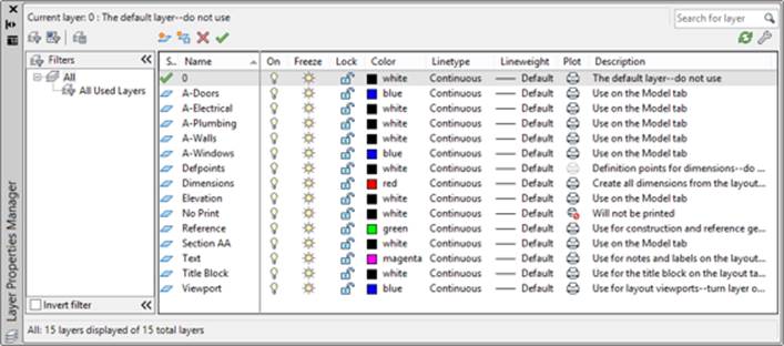
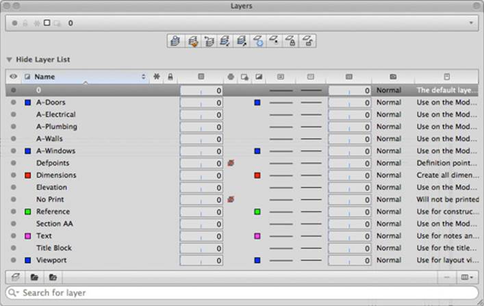
Figure .:
New Group Filter
Organizing objects
Layer States Manager
with layers
New
Property
Create New Layer
Filter
Set Current
Settings
New Layer
New Dynamic Layer Group
Display Settings
New Layer Group
If you are using AutoCAD for Mac, follow these steps to create a new layer:
1. Click Format menu ➢ Layers (or at the command prompt, enter layer and press Enter).
2. On the Layers palette (see Figure 2.3, bottom), click New Layer.
TIP If a layer already exists with the property values that are close to those you need in the new layer you want to create, select the layer that you want to base the new layer on before clicking New Layer.
![]()
![]()
![]()
![]()
![]()
![]()
![]()
![]()
![]()
![]()
![]()
3. Enter a name that follows your company’s established CAD standards.
4. With the new layer’s row selected, do one of the following:
◆ On the Layers palette, click one of the columns that represents the properties of the layer.
◆ On the Properties Inspector palette, on the Layer Properties tab click one of the controls to edit the property’s value.
The following explains what to do after you click on a column in the Layers palette or control in the Properties Inspector palette:
◆ On (Visibility): Toggles the layer on or off. When set to Off, objects on the layer can
still be selected using the All keyword at the Select objects: prompt, and the
objects are regenerated when the drawing’s display is updated.
◆ Freeze: Toggles the freeze and thaw states of the layer. When set to Freeze, objects on
the layer can’t be selected using the All keyword at the Select objects: prompt,
and the objects aren’t regenerated when the display of the drawing is updated.
◆ Lock: Toggles the lock state of the layer. The Lock setting restricts objects on the layer from being selected at the Select objects: prompt.
◆ Color: Choose a color from the drop-down list or choose Select Color to display the
Color Palette dialog box. Select a color value and click OK. For more information, see
“Signifi cance of Colors” later in this chapter.
◆ Linetype: Choose a linetype from the drop-down list or choose Manage to display the
Select Linetype dialog box. Select a loaded linetype and click OK. If the linetype you
want to use is not loaded, click Load and load the layer fi rst. For more information,
see “Defi ning Appearance with Linetypes, Lineweights, and Transparency” later in
this chapter.
◆ Lineweight: Choose a lineweight from the drop-down-list. For more information, see
“Defi ning Appearance with Linetypes, Lineweights, and Transparency.”
◆ Transparency: Click and drag the slide to specify a new transparency value. For
more information, see “Defi ning Appearance with Linetypes, Lineweights, and
Transparency.”
◆ Plot Style: Choose a plot style from the drop-down list.
◆ Plot: Toggles the plottable state of the layer. Objects on the layer that is not plottable are displayed in the drawing window, but the objects are not part of the output when
the drawing is plotted or printed.
◆ New VP Freeze/Freeze In New Viewports: Toggles the freeze and thaw states of the
layer when a new fl oating viewport is created on a named layout.
◆ VP Freeze/Viewport Freeze: Toggles the freeze and thaw states of the layer in the cur-
rent viewport.
![]()
![]()
◆ VP Color, VP Linetype, VP Lineweight, VP Transparency, and VP Plot Style: These
properties can be changed just like the properties without the VP prefi x previously
described.
◆ Description: Edit the description of the layer. Adding a description can be helpful to
those new to or unfamiliar with your CAD standards.
TIP Right-click the column headings in the Layers palette to control the display of which columns you want to display. If there are properties that you commonly do not use, you can turn them off .
5. Repeat steps 2–4 for each layer you want to create.
6. Double-click one of the layers in the Layers list or choose one from the Layers drop-down list at the top of the palette to set it current.
Signifi cance of Colors
The use of color in a drawing serves two distinct purposes. The fi rst is to make objects easy to distinguish from each other, and the second is to control the way the objects in your drawing are output. A majority of drawings use color-dependent plot styles. However, that does not mean they are plotted or printed in color, just that each unique color in a drawing can be used to control not only the color of an object when it is output, but also several other object properties. In addition to color, plot styles can override the linetype, lineweight, and transparency (or screening) values that are assigned to an object directly or that it inherits from the layer. Object and layer colors do not affect the output of objects when you are using named plot styles, the other type of plot styles that AutoCAD supports.
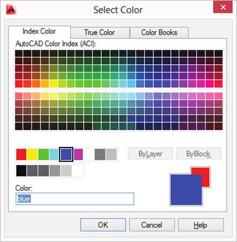
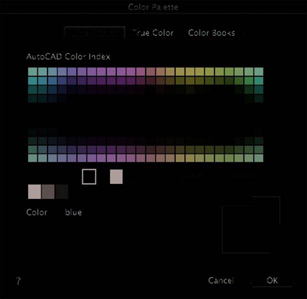
From the Layer Properties Manager (Windows) or Layers palette (Mac OS), clicking the Color column of a layer allows you to display the Select Color dialog box or Color Palette (see Figure 2.4), respectively. This interface allows you to select from one of the AutoCAD index colors (255 unique colors), a true color value, or a color from one of the installed color books. The AutoCAD index colors are the most commonly used for both layers and objects because these values directly map to values in a color-dependent plot style (CTB) fi le. If you need to set an object’s color directly, select the object and use the Color property on the Properties palette (Windows) or Properties Inspector (Mac OS).
Figure .:
Setting the color of
a layer
![]()
Defi ning Appearance with Linetypes, Lineweights, and Transparency
Color is just one property of an object that affects how it appears onscreen and when it is output; the linetype, lineweight, and transparency properties also impact the way objects appear. These properties can be set by object using the Linetype, Lineweight, and Transparency properties on the Properties palette (Windows) or Properties Inspector (Mac OS). However, as I mentioned earlier, it is much more effective to let objects inherit property values from the layer they are placed on.
Linetypes
Linetypes help distinguish objects that make up your design from those that are used to anno-tate it by using gaps, dashes, and text in your linework. Common uses for linetypes are to indicate center lines that pass through the center of a circle or an arc, to show features that are behind or beyond an object with hidden or dashed lines, or even to designate where a utility line runs through a property by displaying text within the linework.
The size of the dashes, gaps, and text in a linetype is determined by the linetype defi nition and two scale factors:
◆ The global scale factor, which is set by the ltscale system variable
◆ The linetype scale assigned directly to an object
The global scale factor is often equal to or half the drawing scale that will be used to output the drawing. If your viewports are set to a scale of 1/4” = 1’-0”, your drawing scale would be a factor of 48, which is calculated by the math statement of (1/4) × 12. Once you know the drawing scale, divide it by 2, and that will give you the range in which your global linetype scale should be—in this example, that range would be 24 to 48.
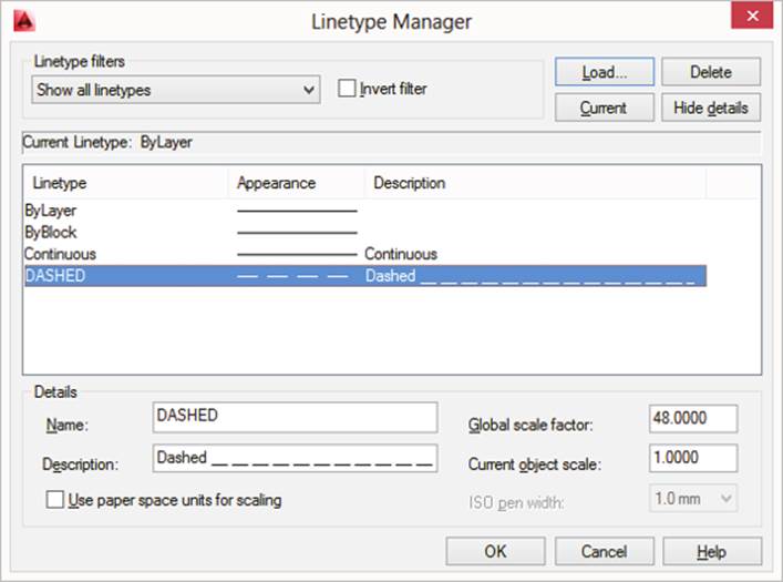
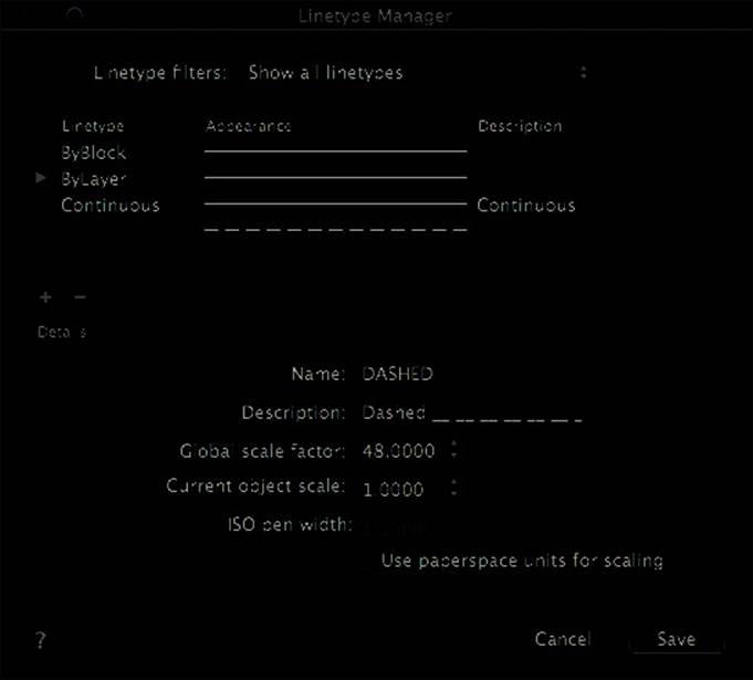
The predefi ned linetypes that come with AutoCAD are stored in the acad.lin and acadiso
.lin fi les. You can create your own linetype defi nitions and store them in the LIN fi les that come with AutoCAD, or you can create your own LIN fi les. Creating custom linetype defi nitions is covered in Chapter 9, “Defi ning Shapes, Linetypes, and Hatch Patterns.” Linetypes must be loaded into a drawing with the Linetype Manager before they can be used. See Figure 2.5; the Windows version is displayed on top, and the Mac OS version is on the bottom. Once loaded, a copy of the linetype defi nition is stored in the drawing. When defi ning the layers in your drawing template fi les, only load the linetypes that are needed.
Lineweights
By default, all linework in a drawing is displayed as a single pixel in width onscreen unless the object is a polyline with a specifi ed width or you use lineweights. Both layers and objects have a Lineweight property, which can be used to control the width or thickness of the linework for the objects in a drawing. Controlling the width of the linework allows you to emphasize the walls of a building or the edges of the main elements in a design while putting less emphasis on dimensions and other annotation objects. The correct balance of lineweight widths used in a drawing can improve how objects within the design are communicated to a client or contractor.
Lineweights are commonly used to control the width in which an object should appear when
plotted or printed, but they can also be used to affect how objects are displayed onscreen. If you
want to display lineweights onscreen, you can use the Show/Hide Lineweight option on the
application’s status bar or change the value of the lwdisplay system variable.
Figure .:
Managing linetypes
and scales
The display of lineweights is different based on whether you are working on the model or in a named layout. The following explains the differences in the way lineweights are displayed.
![]()
Model Layout Independent of the current zoom scale, lineweights are measured in pixels. No matter the current zoom scale of the current view, the width of the linework never increases or decreases when zooming in or out.
Named Layout Lineweights are displayed based on the current zoom scale. Just like placing a magnifying glass over a sheet of paper, the magnifi cation of the drawing makes the linework appear thicker; the same happens when zooming in or out on a layout.
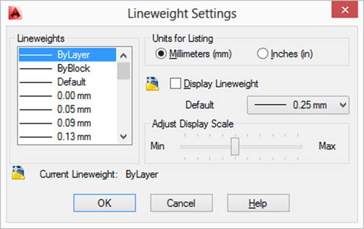
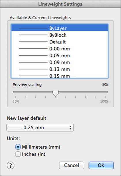
You can modify the settings that affect the display of lineweights in a drawing by using the Lineweight Settings dialog box. See Figure 2.6; the Windows version is displayed on the left, and the Mac OS version is on the right. The Default (Windows) or New Layer Default (Mac OS) drop-down list controls the lineweight used by the Default value of the Lineweight property for layers and objects, which can also be set with the lwdefault system variable. Use the Adjust Display Scale (Windows) or Preview Scaling (Mac OS) slider to control the lineweight scale of all lineweights on the Model layout. The other area that may have some signifi cance is the Units For Listing (Windows) or Units (Mac OS) section, which controls the values in which lineweights are expressed in the AutoCAD user interface: millimeters (mm) or inches (in). Units for listing lineweights can also be controlled with the lwunits system variable.
Figure .:
Controlling
the display of
lineweights
Transparency
Transparency gives you the ability to see through to what is below or beyond an object. Objects can have a transparency value of 0 (fully opaque/solid) to 90 (nearly fully transparent). Unlike lineweights, the display of transparency is much more useful onscreen in a complex drawing, but it can have an impact on the display of your drawing based on your workstation’s hardware.
You can use the Show/Hide Transparency option on the application’s status bar or change the value of the transparencydisplay system variable.
![]()
Controlling Output with Plot Styles
While layers and object properties control much of the way objects are displayed onscreen, you can use plot styles to override those values to alter the way objects are plotted or printed. Plot styles can also be used to affect the way objects appear onscreen if the Display Plot Styles option is enabled in the Page Setup dialog box.
Plot styles are available in two styles: color-dependent and named. When you are using color-dependent plot styles, the name of the plot style is fi xed based on the color value assigned to an object or the layer in which an object is placed. Assigning a named plot style to a layer or object is similar to assigning a linetype: fi rst you specify which named plot style fi le you want to use, and then you specify the plot style you want to assign to the layer or object. For more information on plot styles and how to create them, see Chapter 1, “Establishing the Foundation for Drawing Standards.”
Accessing Layer Settings
Besides the properties for a layer that are accessible from the Layer Properties Manager
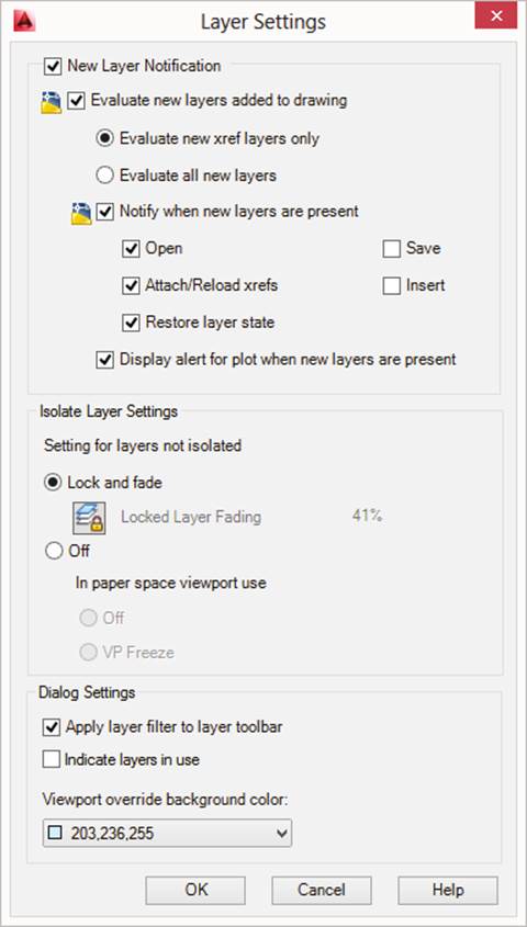
(Windows) or Layers palette (Mac OS), several other settings affect the way layers look or behave in the drawing window. In AutoCAD for Windows, you can use the Layer Settings dialog box (see Figure 2.7) to change the current layer settings, but you can also use a few system variables to change some of these settings. In the dialog box, the settings with a small drawing fi le icon next to them (the blue-and-yellow sheet of paper) indicate that the setting is stored with the drawing.
In AutoCAD for Mac, there is no equivalent to the Layer settings dialog box (many of the
same features in the Windows product are not available on Mac OS), but there are a few settings that you can access using system variables and commands to change your experience.
The Layer Settings dialog box in AutoCAD on Windows can be displayed by doing the
following:
1. On the ribbon, click Home tab ➢ Layers panel ➢ Layer Properties.
2. In the Layer Properties Manager, click Settings, located near the upper-right corner.
Fading Objects on Locked Layers
Locking a layer ensures that the objects on that layer are not accidentally selected when editing other objects in a drawing, but they still can be used as reference geometry. To help make it easy to identify when a layer is locked, AutoCAD fades the objects on a locked layer so they are less prominent in the foreground. You can toggle this feature on and off, as well as control the amount objects are faded. By default, objects on locked layers are faded by 50 percent.
To change the amount a layer is faded, you can do one of the following:
◆ In the Layer Settings dialog box (see Figure 2.7), in the Isolate Layer Settings section, choose Lock And Fade, and then drag the Locked Layer Fading slider. If the slider is not
enabled, click the Locked Layer Fading toggle (the stack of three papers with a lock icon) and then drag the slider. Click OK (Windows).
◆ On the ribbon, select Home tab ➢ Layers panel, click the panel’s title to expand the panel, and drag the Locked Layer Fading slider. If the slider is not enabled, click the Locked
Layer Fading toggle (the stack of three papers with a lock icon) and then drag the slider (Windows).
◆ At the command prompt, enter laylockfadectl and press Enter. Enter a new fade value and press Enter. Entering a negative value disables the fading of objects on a locked layer (Windows and Mac OS).
Figure .:
Changing layer set-
tings aff ects the
way you work with
layers in the draw-
ing window and
user interface.
Isolating Objects; Turning Off or Locking
Isolating layers allows you to quickly turn off or lock layers, work with objects on other layers in the drawing, and then quickly restore the previous state of the layers in the drawing. Layers can be isolated with the layiso command, and isolation can be reversed (unisolated) with the layuniso command. You can control the default isolation mode that the layiso command uses.
To change the isolation mode of the layiso command, you can do one of the following:
◆ In the Layer Settings dialog box (see Figure 2.7), in the Isolate Layer Settings section, choose Lock And Fade to lock the layers when using layiso or click Off to turn them off
instead. When you click Off, you have the option to turn the layer off or to freeze it in the current viewport when using layiso in a fl oating viewport. Click OK (Windows).
◆ At the command prompt, enter layiso and press Enter. Use the Settings option and specify the mode to use (Windows and Mac OS).
Evaluating and Reconciling New Layers
It is not uncommon to need a new layer here and there that deviates from your company’s CAD
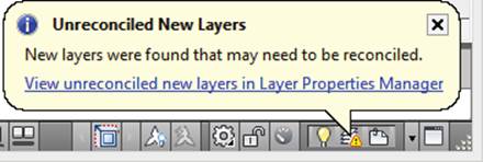
standards, but new layers can affect the way a drawing is plotted or printed based on how that layer was defi ned. AutoCAD on Windows and Mac OS has a feature known as New Layer Notifi cation, but it works slightly differently on the two platforms. On Windows, when the New Layer Notifi cation feature is enabled and a new layer has been added to a drawing, a notifi -
cation balloon (see Figure 2.8) is displayed, and a new layer fi lter named Unreconciled New Layers is created in the Layer Properties Manager. By default, the notifi cation of new layers happens when an external reference is being attached, when a drawing is opened, when an xref is attached/reloaded, and when a layer state is restored.
Figure .:
Unreconciled layer
notifi cation balloon
On Mac OS, the feature is disabled out-of-the-box, so it must fi rst be enabled. The notifi cation balloon is not available on Mac OS, but the Unreconciled New Layers fi lter is created in the Layers palette when the feature is enabled and the correct conditions are met.
You can modify the settings of the New Layer Notifi cation feature from the Layer Settings dialog box (see Figure 2.7) in AutoCAD on Windows, or with the following system variables on both Windows and Mac OS:
layereval Controls whether the layers in a drawing should be evaluated only when an xref is attached, or when a new layer is created in addition to when an xref is attached.
layerevalctl Disables or enables the New Layer Notifi cation feature.
layernotify Specifi es which drawing editor events display an alert message when layerevalctl is set to 1.
To reconcile a layer in AutoCAD on Windows, you need to perform the following steps:
1. On the ribbon, click Home tab ➢ Layers panel ➢ Layer Properties.
2. On the Layer Properties Manager, select the Unreconciled New Layers fi lter from the Filter Tree located on the left side. (If the Filter Tree is not displayed, right-click in the Layers list and click Show Filter Tree.)
3. In the Layers list, select the layers you want to reconcile and then right-click. Click Reconcile Layer.
4. Save the drawing. If saving a drawing is one of the events that triggers the Unreconciled New Layers notifi cation, the balloon will be displayed each time a drawing is saved if
you do not reconcile (or remove) all of the offending layers from the drawing.
Reconciling a layer in AutoCAD for Mac OS requires actions similar to those used on
Windows. You can reconcile a layer on Mac OS using the following procedure:
1. Click Format menu ➢ Layers.
2. In the Layers palette, expand the Unreconciled New Layers fi lter from the Layers list. If the fi lter is not displayed, click Display Settings in the lower-right corner of the Layers palette and click Show Layer Groups; the option should now be checked. To make sure
Unreconciled Layers is also checked, click Display Settings ➢ Show Automatic Groups ➢ Unreconciled Layers.
3. In the Layers list, select the layers you want to reconcile and right-click. Click Reconcile Layer.
4. Save the drawing.
For more information on the New Layer Notifi cations feature and reconciling layers, see the AutoCAD Help system.
Controlling the Layer Properties Manager and Ribbon Controls
(Windows Only)
There are several settings that you can use to alter your experience with the Layer Properties Manager and the Layer list on the ribbon. These settings can be found under the Dialog Settings section of the Layer Settings dialog box (see Figure 2.7). The settings that can be changed: Apply Layer Filter To Layer Toolbar (or Layer Drop-Down List on the Ribbon) This option aligns the list of layers displayed in the Layer Properties Manager with the Layer control on the Layer toolbar or Layers panel of the ribbon. This is helpful when working with drawings that contain hundreds of layers.
Indicate Layers In Use Use this option to control whether the icon in the Status column is updated to refl ect if at least one object is placed on that layer in the drawing. This option can also be controlled with the showlayerusage system variable.
Viewport Override Background Color This option enables the highlighting of layers with viewport overrides in the Layers list of the Layer Properties Manager, or those in the Layer drop-down list on the Layer toolbar or Layers panel of the ribbon.
In addition to the settings under the Dialog Settings section of the Layer Settings dialog box, you can right-click the Layers list of the Layer Properties Manager to control the display of the Filter Tree and whether fi lters appear in the Layers list. You can also right-click a column heading in the Layers list to control which columns are displayed, or click and drag a column heading to reorder the columns. Clicking and dragging between columns adjusts the width of the column to the left.
Controlling the Layers Palette (Mac OS Only)
The Layers palette in AutoCAD for Mac doesn’t have as many settings that control its behavior as the Layer Properties Manager in AutoCAD on Windows, but there are a few settings that can improve your experience. These settings are available from the Settings menu, which you can display by clicking the Display Settings button located in the lower-right corner of the Layers palette. These settings are available on the Settings menu:
Show Layer Groups This option controls the display of layer groups within the Layers list. You can also control where the layer groups are displayed: at the top or bottom of the Layers list.
Show Empty Groups Use Show Empty Groups to display or hide layer groups that do not have any layers in them.
Show Xref Layers This option controls the display of layers from attached xrefs in the Layers list.
Show Automatic Groups Show Automatic Groups controls the display of auto-generated layer groups based on specifi c criteria: all used layers, attached external references, layers with viewport overrides, and unreconciled layers.
View Options This option controls which columns are displayed in the Layers list.
You can also right-click a column heading to control which columns are displayed, or click and drag a column heading to reorder the columns. Clicking and dragging between columns
adjusts the width of the column to the left.
Grouping and Filtering Layers
Filters in the Layer Properties Manager (Windows) or Layers palette (Mac OS) allow you work with groupings of layers much like you would an individual layer. AutoCAD creates a few layer fi lters dynamically based on events that happen in the drawing window, such as attaching an xref or creating a viewport override on a layer. You can also create one of two types of layer fi lters based on your own conditions:
Group Filter Using a group fi lter, you can create a static grouping of layers that are manually selected.
Dynamic or Property Filter Using a dynamic or property fi lter, you can create a grouping of layers defi ned by the properties they have in common.
You can create a group fi lter and add layers to it by taking the following steps:
1. Do one of the following:
◆ On the Layer Properties Manager, click New Group Filter (Windows).
◆ On the Layers palette, click New Layer Group (Mac OS).
2. Enter a descriptive name for the new group and press Enter.
3. Drag and drop layers from the Layers list onto the new group to create an association between the layers and group.
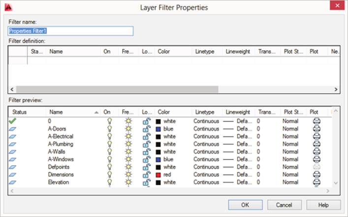
A property fi lter in AutoCAD on Windows can be created by following these steps:
1. On the Layer Properties Manager, click New Property Filter.
2. When the Layer Filter Properties dialog box (Figure 2.9, top) opens, enter a descriptive name in the Filter Name text box.
3. In the Filter Defi nition grid, set the properties you want to fi lter on. Click OK.
Figure .:
Creating dynamic
fi lters based on
layer names and
properties
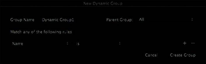
If you are using AutoCAD for Mac, do the following to create a dynamic fi lter:
1. On the Layers palette, click New Dynamic Layer Group.
2. When the New Dynamic Group dialog box (Figure 2.9, bottom) opens, enter a descriptive name in the Group Name text box.
3. In the Match Any Of The Following Rules section, set the properties you want to fi lter on.
4. Optionally, click the + (plus) button to add properties to the fi lter.
5. Click Create Group.
Creating and Using Layer States
Layer states allow you to take a snapshot of the current layers in a drawing. The snapshot includes the layers that currently exist in the drawing and their current property values. Any new layers added to a drawing are not automatically added to an existing layer state because they did not exist when the layer state was created. When a layer state is restored and new layers exist in the drawing, you have the option to turn off any layers that weren’t saved with the layer state.
After you make changes to the layers in the drawing for editing, plotting, or display purposes, you can return the layers to their previous properties by restoring a saved layer state.
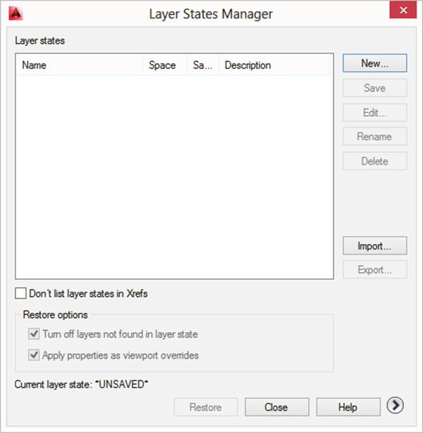
Layer states can be benefi cial when you receive a drawing from a client and want to make sure that the layers are just like they were when you received the drawing before sending it back to the client. You can create layer states in AutoCAD on Windows by using the Layer States Manager dialog box (see Figure 2.10) or with the State option of the -layer command. The
Layer State Manager does not exist in AutoCAD for Mac, so you need to use the State option of the -layer command.
The following steps explain how to create a layer state in AutoCAD on Windows:
1. On the ribbon, click Home tab ➢ Layers panel ➢ Layer States drop-down list ➢ Manage Layer States (or at the command prompt, enter layerstate and press Enter).
2. When the Layer States Manager (Figure 2.10) opens, click New.
3. In the New Layer State To Save dialog box, enter a name in the New Layer State Name text box. Optionally, enter a description. Click OK.
4. Optionally, click Edit to edit the layers and the properties that are being saved with the layer state. Make the edits in the Edit Layer State dialog box and click OK.
5. Click Save and then click OK.
Figure .:
Saving layer states
allows you to later
restore the visibil-
ity and properties
of the layers in a
drawing.
If you are using AutoCAD for Mac or want to create a layer state from the command prompt
in AutoCAD on Windows, do the following:
1. At the command prompt, enter -layer and press Enter.
2. At the Enter an option [?/Make/Set/New/Rename/ON/OFF/Color/Ltype/LWeight
/TRansparency/MATerial/Plot/PStyle/Freeze/Thaw/LOck/Unlock/stAte/
Description/rEconcile]: prompt, type state and then press Enter.
3. At the Enter an option [?/Save/Restore/Edit/Name/Delete/Import/EXport]:
prompt, type save and then press Enter.
4. At the Enter new layer state name: prompt, type a name for the new layer state and then press Enter.
5. At the Enter states to change [On/Frozen/Lock/Plot/Newvpfreeze/Color/line-
Type/lineWeight/TRansparency/plotStyle]: prompt, type a property to change and
then press Enter, or simply press Enter if you don’t want to make any changes to the new
layer state.
6. Press Enter again to end the -layer command.
A layer state after it is saved can be restored by doing one of the following:
◆ In the Layer States Manager, select the layer state you want to restore and click Restore (Windows).
◆ On the ribbon, click Home tab ➢ Layers panel ➢ Layer States drop-down list and select the layer state you want to restore (Windows).
◆ At the command prompt, type -layer and press Enter. At the Enter an option prompt, type state and press Enter. At the Enter an option prompt, type restore and press Enter. At the Enter name of layer state to restore or [?]: prompt, type the name
of the layer state to restore and press Enter. Press Enter again to end the -layer command (Windows and Mac OS).
Creating and Managing Annotation Styles
Annotation styles play a signifi cant role in the communication of your design to those who will sign off on the project or be involved in manufacturing. AutoCAD supports four primary annotation styles that affect the appearance of text, dimension, table, and multileader objects.
The following sections explain the basics of creating and editing these annotation styles.
Text Heights
The height at which any text should be created is based on where the text will reside: model space or paper space. Text created in model space (using the Model tab) is commonly scaled up because the objects represent real-world objects that are being designed and drawn at full scale and then are scaled down when plotted or printed to fi t on a sheet of paper.
Text at a height of 3/16” (or 0.1875 inches) is very small in model space if you normally use a plot scale of 1/8” = 1’-0” or 100:1 for your drawings. The text would be plotted at about
0.0019 inches high, or basically a dot on the drawing. To get an acceptable size for your text in model space, you take the text height you want the fi nal text to appear, say 3/16”, and multiply it by the expected plot scale (1/8” = 1’-0” is equal to 96). So you take (3/16) × 96 to calculate the fi nal text height of 18” to be used for text in model space. On the other hand, 18” is way too large for text in paper space. Here, you would use the actual text height of 3/16” since you commonly plot or print a layout at a scale of 1:1.
Things can get complicated even further if you plot parts of your drawing at different scales since your text would not look the same when plotted at a scale of 1/4” = 1’-0” as it would at 100:1. The issue of dealing with multiple plot scales in a drawing can be addressed with one of two solutions:
◆ Use different layers and create multiple text objects at different heights; then control which objects should be displayed in a viewport at a specifi c scale or when the drawing is plotted.
Managing multiple layers and annotation objects was once the only choice, but it is still the common choice for some companies.
◆ Use annotative scaling to dynamically scale text up or down based on the scale at which the object is being viewed through a viewport or plotted. I discuss annotative styles and annotation scaling in the section “Annotative Styles and Annotation Scaling” later in this chapter.
Text Styles
Text styles are used to defi ne how text within a drawing will look or behave when created, but not what the contents of the text will be. For example, a text style defi nes which font will be used to control the appearance of the characters within a text object, if the text is bold or italicized, the default height of the text, or if the object will be annotative when a new text object is created.
Text styles in AutoCAD can be defi ned to use one of two font types:
Shape (SHX) Fonts Shape fonts are optimized for and only work with AutoCAD. Shape fonts are defi ned through a series of vectors, which make them more effi cient than TrueType fonts. Shape fonts are also used when specifying a Big Font fi le to use for Asian languages.
You can create your own custom fonts or characters by defi ning them in a Shape (SHP) fi le. I discuss creating shapes in Chapter 9.
TrueType (TTF) Fonts TrueType fonts are common to the operating system and other applications on a workstation. They offer a wider range of looks than the SHX fi les do, but they can impact the performance of zooming and object selection in AutoCAD.
Make sure the fonts that you choose to use are easy to read; at the end of the day, annotation is about communicating your design, not for winning awards at an art show. The fonts you pick can affect sharing or exchanging of drawings, too. If a font is not available on a workstation that opens the drawing, a substitute font is used and the text might not appear properly. When a font is not available, AutoCAD replaces the missing font with the one specifi ed by the fontalt system variable.
Creating and Modifying Text Styles
Text styles are created and modifi ed using the Text Style dialog box, which is displayed with the style command. The process for creating and modifying a text style is similar on Windows
and Mac OS. There are some minor differences because of the way the dialog boxes are laid out.
After a text style has been created with the Text Style dialog box, you use the dialog box again to make changes by selecting the style you want to edit from the Text Styles list and changing the properties of that style. Once the property changes are made, you click Apply to save the changes. If you want to create or modify text styles using scripts or custom programs, you can use the -style command.
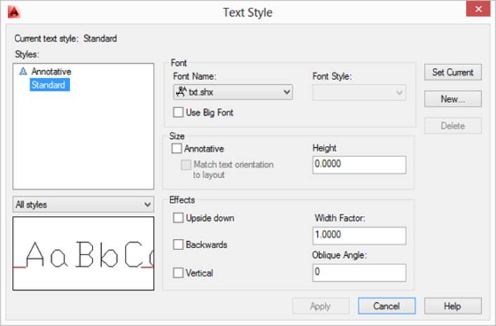
The following explains how to create a text style in AutoCAD on Windows:
1. On the ribbon’s Annotate tab ➢ Text panel, click the panel-launcher button located to the right of the Text panel’s title (or at the command prompt, enter style and press Enter).
2. When the Text Style dialog box (Figure 2.11, top) opens, click New. Enter a name for the new text style and click OK.
3. Select a TTF or SHX fi le from the Font Name drop-down list. Choose an option from the Font Styles drop-down list as needed. If you need to create a style with a Big Font, select an SHX font and click Use Big Font. Then, specify a font from the Big Font drop-down list.
4. Enter a text height in the Height box. The value entered becomes the default text height when you create text objects. It also affects other annotation styles that use the text
style. You can create annotative text, which I cover in the section “Annotative Styles and Annotation Scaling” later in this chapter.
5. In the Effects section, specify any of the options needed for your text style.
6. Click Apply.
7. Double-click the text style you want to make current. When no objects are selected, you can also set a text style as current from the Text Style drop-down list, which is available on the ribbon’s Annotate tab ➢ Text panel.
8. Click Close.
If you are using AutoCAD for Mac, you can do the following to create a text style:
1. Click Format menu ➢ Text Style (or at the command prompt, enter style and press Enter).
2. When the Text Style dialog box (Figure 2.11, bottom) opens, click the + (plus) button located in the lower-left corner. Enter a name for the new text style and press Enter.
3. Select a TTF or SHX fi le from the Family list box. Choose an option from the Typeface list box as needed. If you need to create a style with a Big Font, select an SHX font and then select a font from the Asian Set list box.
4. Enter a text height in the Text Height box. The value entered becomes the default text height when you create text objects; it also affects other annotation styles that use the text style too. You can create annotative text as well, which I cover in the section “Annotative Styles and Annotation Scaling” later in this chapter.
5. Specify any of the effects in the Text Style Preview area as needed.
6. Click Apply.
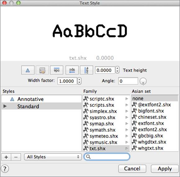
7. Double-click the text style you want to make current. You can also set a text style as current from the Text Style drop-down list in the Annotation section of the Properties
Inspector when no objects are selected.
8. Click Close.
Figure .:
Th
e appearance of
text can be con-
trolled with text
styles.
Using a Text Style with Dimension, Table, and Multileader Styles
When you create a text style, you have the option to specify a default text height for use when you create new text objects. Setting a text height to a specifi c value also forces any dimension, table, or multileader styles that reference that text style to take on the text height to which the text style is set. Don’t use a specifi c text height when you defi ne text styles unless you wish to restrict fl exibility in changing heights when creating text objects or using a text style with other annotation styles.
Dimension Styles
Dimension objects are made up of a number of different components, from arrowheads to extension and dimension lines to annotation objects with formatted values. All of the components that make up a dimension object are defi ned using dimension styles. Dimension styles allow you to control the text size and placement, dimension and extension line colors and linetypes, as well as a dimension scale, which is used to scale up or down the various components of a dimension so that they display correctly based on a drawing’s plotted scale.
Dimension styles are created and modifi ed using the Dimension Style Manager, which is displayed with the ddim command. If you want to create or modify dimension styles using scripts or custom programs, you will want to take a look at the -dimstyle command and the dozens of system variables that all begin with the letters dim.
TIP You can use the Compare button or option from the Dimension Style Manager to see the diff erences between two diff erent dimension styles.
You can create a dimension style on Windows or Mac OS with these steps:
1. Do one of the following to display the Dimension Style Manager:
◆ On the ribbon’s Annotate tab ➢ Dimensions panel, click the panel-launcher button
located to the right of the Dimensions panel’s title (Windows).
◆ Click Format menu ➢ Dimension Style (Mac OS).
◆ At the command prompt, enter ddim and press Enter (Windows and Mac OS).
Figure 2.12 shows the Dimension Style Manager as it appears in Windows (top) and Mac OS
(bottom).
2. In the Dimension Style Manager, click New (Windows) or the + (plus) button (Mac OS).
3. In the Create New Dimension Style dialog box, enter a name for the new style.
4. Optionally, do the following:
◆ Select an existing style to start with and check Annotative if you want to create an
annotative style. I discuss annotative styles in the section “Annotative Styles and
Annotation Scaling” later in this chapter.
◆ Select an option from the Use For drop-down list to have the new dimension style
apply only to a subset of dimension objects. Typically, keep the Use For drop-down
list set to All Dimensions.
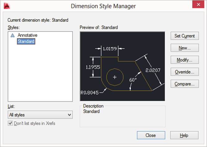
Figure .:
Creating and
defi ning dimen-
sion styles
5. Click Continue.
6. When the New Dimension Style dialog box opens, start on the Lines tab and change the settings as needed.
7. Continue making changes on each tab in the dialog box.
8. Click OK to return to the Dimension Style Manager.
9. Right-click the dimension style you want to make current and click Set Current. When no objects are selected in AutoCAD on Windows, you can also set a dimension style as
current from the Dimension Style drop-down list on the Annotate tab ➢ Dimensions
panel on the ribbon. When no objects are selected in AutoCAD for Mac, you can set a
dimension style as current from the Dimensions Style drop-down list in the Annotation
section of the Properties Inspector.
10. Click Close.
You can edit a dimension style by doing one of the following when the Dimension Style
Manager is displayed:
◆ Select a dimension style from the Styles list box and click Modify (Windows).
◆ Select a dimension style from the Styles list box, click the Action button (the gear icon), and then click Modify (Mac OS).
Dimension overrides, which allow you to apply a temporary change to a style, can also be
created. The changes based on the overrides are added to new objects that are created when the dimension style is current; existing dimensions are not affected by the override. You create an override to a dimension style much like you would modify a dimension style, except that instead of clicking the Modify button/option you click Override. You can also override the properties of individual dimension objects by using the Properties palette (Windows) or Properties Inspector (Mac OS).
Table Styles
Table styles are used to control the direction in which content fl ows for a table, as well as the appearance of the grid border lines and textual content that appears in table cells that are assigned a given style. A table style can also contain cell styles that are used to group general formatting, text, and border settings for use in a table.
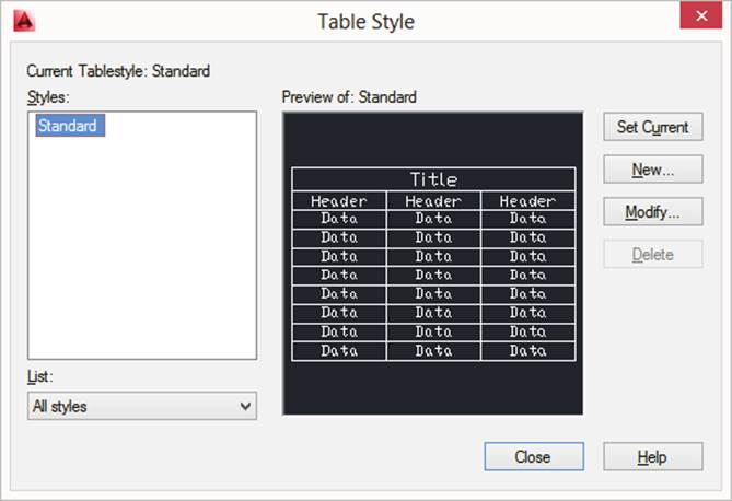
AutoCAD on both Windows and Mac supports the creation of tables and the use of table
styles, but only AutoCAD on Windows allows you to create and modify table styles using the Table Style dialog box (shown in Figure 2.13). The Table Style dialog box is displayed with the tablestyle command. Once a table is created, you can override the properties of a table and its cells using the Properties palette (Windows) or Properties Inspector (Mac OS).
You can create a table style with these steps:
1. On the Annotate tab, Tables panel, click the panel-launcher button located to the right of the Tables panel’s title (or at the command prompt, enter tablestyle and press Enter).
2. In the Table Style dialog box (see Figure 2.13), click New. Enter a name for the new table style and, optionally, select a style to start with. Click Continue.
3. In the New Table Style dialog box, select a table direction in the General section.
4. Optionally, click Create A New Cell Style in the Cell Styles section. In the Create New Cell Style dialog box, enter a name for the new cell style and, optionally, select a style to start with. Click Continue.
5. Select a cell style to edit from the Cell Styles drop-down list in the Cell Styles section.
6. Edit the properties for the cell style on the General, Text, and Borders tabs.
7. Click OK to return to the Table Style dialog box.
8. Select the table style you want to make current and click Set Current.
9. Click Close.
Figure .:
Updating the
properties of a
table style
You can update a table style with the Table Style dialog box by selecting the style you want to edit from the Table Styles list and clicking Modify. Edit the properties of the style as needed, and then click OK to save the changes and exit the dialog box.
Multileader Styles
Multileaders allow you to place text, blocks, or tolerances with leader lines that point to features in your drawing. You use multileader styles to control the creation and appearance of multileader objects. A multileader style specifi es the formatting of the leader line (segment types, colors, and arrowhead style), leader structure (constraints, landing, and scale), and the content that should be displayed at the end of the leader landing. Multileader styles are created and modifi ed using the Multileader Style Manager, which is displayed with the mleaderstyle command.
You can create a multileader style on Windows or Mac OS by taking these steps:
1. Do one of the following to display the Multileader Style Manager (see Figure 2.14):
◆ On the ribbon’s Annotate tab ➢ Leaders panel, click the panel-launcher button located
to the right of the Leaders panel’s title (Windows).
◆ Click Format menu ➢ Multileader Style (Mac OS).
◆ At the command prompt, enter mleaderstyle and press Enter (Windows and Mac OS).
2. In the Multileader Style Manager, click New (Windows) or the + (plus) button (Mac OS).
3. In the Create New Multileader Style dialog box, enter a name for the new style.
4. Optionally, select an existing style to start with and check Annotative if you want to create an annotative style. I discuss annotative styles in the next section, “Annotative Styles and Annotation Scaling.”
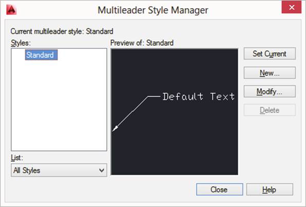
Figure .:
Modifying a multil-
eader style
5. Click Continue. The Modify Multileader Style dialog box is displayed.
6. In the Modify Multileader Style dialog box, start on the Leader Format tab and change the settings as needed.
7. Continue making changes on each tab in the dialog box.
8. Click OK to return to the Multileader Style Manager.
9. Right-click the dimension style you want to make current and click Set Current. When no objects are selected in AutoCAD on Windows, you can also set a multileader style
as current from the Multileader Style drop-down list on the Annotate tab ➢ Leaders
panel on the ribbon. When no objects are selected in AutoCAD for Mac, you can use the
Multileader Style drop-down list in the Annotation section of the Properties Inspector.
10. Click Close.
You can edit a multileader style by doing one of the following when the Multileader Style Manager is displayed:
◆ Select a multileader style from the Styles list box and click Modify (Windows).
◆ Select a multileader style from the Styles list box, click the Action button (the gear icon), and then click Modify (Mac OS).
Annotative Styles and Annotation Scaling
As I mentioned earlier, in the “Text Heights” section, calculating and displaying text at the correct height in a drawing can be a bit of a challenge when working with one or even several drawing scales. It can even be more time-consuming if you decide to change the scale at which your drawing should be plotted.
These problems can be solved through the use of annotative styles and annotation scaling.
When you use annotative styles and annotation scaling, you specify the fi nal height for your text objects and AutoCAD does the calculations for you based on the scale assigned to a viewport or when a drawing is plotted. For example, you set a text style to be annotative and then
specify a paper height (the size the text should appear on the drawing when plotted). Specifying a text height of 1/8” means that the text will appear as 1/8” on the sheet of paper as long as you have assigned the correct annotation scales to the text object. Entering 1/8” is so much easier than calculating a text height of (1/8) × 96 = 12, so your text is printed as 1/8” high when your viewport is set to a scale of 1/8” = 1’-0”.
Okay, there are a few additional steps that need to happen, but it is much easier to let
AutoCAD manage the display of annotation objects based on the current annotation scale than to create a large number of annotation objects at different sizes on different layers. The following styles can be set as annotative, which results in the creation of objects that are annotative and react to the current annotation scale in a drawing:
◆ Dimension styles
◆ Multileader styles
◆ Text styles
The following objects can be created using annotative styles or by enabling the Annotative property using the Properties palette (Windows) or Properties Inspector (Mac OS):
◆ Attribute defi nitions
◆ Block defi nitions/references
◆ Dimensions
◆ Geometric tolerances
◆ Hatch objects
◆ Multileaders
◆ Single-line and multiline text
Creating an Annotative Style
You can use the following to create an annotative text, dimension, or multileader style:
Text Style Create a text style as explained earlier, in the “Creating and Modifying Text Styles” section. Then, before saving the new style, in the Text Style dialog box check
Annotative in the Size section in AutoCAD on Windows or click the Annotative toggle in
AutoCAD for Mac. Enter the fi nal height for the text in the Paper Text Height text box, and optionally click the Match Text Orientation To Layout check box (Windows) or toggle (Mac
OS). Now the size of the text will be scaled up or down based on the annotation scales
assigned to the single-line or multiline text objects that are created with that style current.
Dimension Style Create a dimension style as explained earlier, in the “Dimension Styles”
section. Then, before saving the new style, in the New/Modify Dimension Style dialog box
select the Fit tab and check Annotative in the Scale For Dimension Features section. Now
the size, text height, and other distances that affect the appearance of dimension objects are scaled up or down based on the annotation scales assigned to the dimension objects that
are created with that style current.
Multileader Style Create a multileader style as explained earlier, in the “Multileader Styles” section. Then, before saving the new style, in the Modify Multileader Style dialog box select the Leader Structure tab and check Annotative in the Scale section. Now the size, text height, and landing gap values on the Leader Format and Content tabs are scaled up or down based on the annotation scales assigned to the multileader objects that are created with that style current.
I explain creating annotative blocks in Chapter 3, “Building the Real World One Block
at a Time.”
Managing Annotation Scales for an Object
After an annotation object is created with an annotative style current or the object’s Annotative property is enabled with the Properties palette (Windows) or Properties Inspector (Mac OS), you need to assign the annotation object one or more annotative scales. Annotative scales can be assigned to an annotation object using the objectscale command, or with the Annotative Scale property in the Properties palette (Windows) or Properties Inspector (Mac OS) when the object is selected.
Each annotative scale assigned to an annotation object creates an additional representation of the object; this allows you to control the placement of each representation independently while managing the content through a single object. Which representation of an annotation object should be displayed is determined by the current annotation scale of a viewport or when the drawing is plotted. For example, you can assign the annotative scales of 1/4” = 1’-0” and 1/8” =
1’-0” to your annotation objects, and if a viewport is set to the scale of 3/16” = 1’-0” none of the annotation objects are displayed. This is because your annotation objects were only assigned the scales of 1/4” = 1’-0” and 1/8” = 1’-0”.
The current annotation scale for a viewport can be specifi ed using the Annotation Scale
drop-down list on the status bar. This value determines which annotation objects are displayed in the drawing based on their assigned annotative scales. You can add annotative scales automatically to all annotation objects when switching the value of the Annotation Scale drop-down list by enabling Automatically Add Scales To Annotative Objects on the status bar. If you are working in a drawing that has annotative objects with multiple annotative scales assigned to them, you might want to enable the Annotation Visibility option on the status bar as well so that you can adjust the placement of each representation of your annotation objects without switching between annotation scales.
Defi ning and Managing Other Nongraphical Objects
All of the drawings you create should contain a standard set of layers and annotation styles to ensure they have a consistent appearance from one drawing to the next. There are other nongraphical objects that you should consider standards for based on the types or sizes of the drawings that your company creates. Just as I recommended placing the layers and annotation styles that you frequently use in your drawing templates, you might want to do the same for some of the nongraphical objects mentioned in this section, especially if you work on 3D models.
Because these nongraphical objects are less frequently used, I mention them here only briefl y; you can fi nd more information by using the AutoCAD Help system. Most of these nongraphical
objects are supported on both Windows and Mac OS, but there are some limitations and I note some of those next.
Multiline Styles Multiline objects are used to create two or more parallel lines that might represent roadway, sidewalk, or utility offsets from a road. These offsets are defi ned as part of a multiline style. Although multiline styles are supported on both Windows and Mac OS, only the Windows version supports the mlstyle command, which allows you to create multiline styles directly from inside AutoCAD. On Windows and Mac OS, you can defi ne multiline styles outside of AutoCAD by editing the acad.mln fi le with an ASCII text editor such as Notepad (Windows) or TextEdit (Mac OS).
View Styles View detail and section styles are used to control the appearance of associated detail and section views that are generated from 2D drawings created with AutoCAD and 3D
models created with Autodesk Inventor®. You use the viewdetailstyle and viewsection-
style commands to create and modify view detail and section styles. (This option is not supported on Mac OS.)
Views Panning and zooming in large drawings can become ineffi cient after a while, especially if you fi nd yourself moving between the same areas of a drawing over and over again.
Named views allow you to defi ne a rectangular area of a drawing and give it a name. You
can quickly return to that view by selecting its name from the Viewport Controls displayed in the upper-left corner of the drawing window. Named views are much more commonly
used in 3D than 2D drawings to control the background of the current viewport. You use the view command to create named views. The Windows version of the command displays a dialog box, but the Mac OS version of the command is command-line–based only. Both versions
of the command share the same options, with the exception of the Background and Shot
Properties options, which are available on Windows only.
User Coordinate Systems (UCSs) All drawings contain a world coordinate system (WCS), which works well when you are drawing from a plan view. A user coordinate system (UCS)
allows you to change the orientation of the working plane (X,Y) in addition to the Z-axis or placement of a drawing’s origin. If you are drawing objects that are very far from the origin (0,0) of a drawing in 2D, adding ordinate dimensions, or using pattern fi lls, you might want to defi ne a new origin to make entering coordinate values or controlling the pattern placement for a hatch object easier. UCSs are much more commonly associated with 3D modeling,
though, because they allow you to align the UCS with the face of an object or change the
direction of the Z-axis and the current working plane so that you can draw 2D objects at different angles in 3D space and then extrude them. The ucs and ucsman commands are used to
create and manage named UCSs.
Model Space Viewports You can divide model space (using the Model tab) into more than one viewport and then save it as a viewport confi guration. This approach is useful if you are working on a 3D model because it allows you to start a command in one viewport and switch to another viewport that has a different view to fi nish the command. It can be helpful when you are working on large drawings as well. You use the vports command to create named
viewport confi gurations or restore the original single-viewport confi guration.
Visual Styles Looking at 3D models in wireframe can make it hard to tell what is going on at times, and rendering your model can take some time based on the lighting, materials, and other rendering settings that are applied. Visual styles allow you to control a number of settings that affect the appearance of 3D objects. They can be used to show only the visible edges from the current viewpoint, apply colors of shading, and even make 3D objects
appear semitransparent to see the objects beyond. Visual styles can be created and modifi ed in AutoCAD on both Windows and Mac OS, but the process is slightly different. In AutoCAD
on Windows, you use the visualstyle command to display the Visual Styles Manager, but
in AutoCAD for Mac you use a combination of the Visual Style section on the Properties
Inspector (properties command) when no objects are selected and the vssave command to
save the changes to a visual style.
Materials Materials help bring your 3D models to life by applying real-world materials to your virtual design. Using materials makes your models appear more alive and helps communicate what the fi nal item or building might look like once manufactured or constructed.
Materials can be assigned patterns, textures, colors, and other properties to represent tiles, bricks, glass, plastics, and much more. Both the Windows and Mac OS version of AutoCAD
allow you to apply materials to 3D objects, but only AutoCAD on Windows lets you defi ne
and modify materials. You use the materials command when you want to work with
materials.
Render Presets Rendering can be a complex process because of the number of settings that can be controlled. Using render presets makes this process much easier because it allows you to specify the rendering settings you commonly use and then save them as a custom render
preset that you can use to render a 3D model to an image or when plotting. You can use render presets when rendering in AutoCAD on Windows or Mac OS, but render presets can be
created only in AutoCAD on Windows with the renderpreset command.
Removing Unused Nongraphical Objects
Nongraphical objects cannot be simply removed from a drawing with the erase command,
and only nongraphical objects that are not being referenced or used can be removed from a drawing. The removal of nongraphical objects is handled with the purge command. In addition to removing nongraphical objects from a drawing, the purge command can be used to remove
registered application IDs created by third-party programs, non-zero–length lines, and empty text objects. It is good practice to remove the nongraphical objects you no longer need or are not using.
Follow these steps to remove all unused nongraphical objects from the current drawing in
AutoCAD for Windows:
1. Click the Application button ➢ Drawing Utilities ➢ Purge (or at the command prompt, type purge and press Enter).
2. In the Purge dialog box, clear Confi rm Each Item To Be Purged and check Purge Nested Items. The Confi rm Each Item To Be Purged option, when checked, displays a message
box that prompts you to verify the removal of each unused nongraphical object, and the
Purge Nested Items option checks for additional nongraphical objects after all the cur-
rently identifi ed unused objects have been removed.
3. Click Purge All. Doing so removes all unused nongraphical objects from the drawing.
4. Click Close.
Follow these steps to remove all unused nongraphical objects from the current drawing
using the command-line version of the purge command available in AutoCAD for Windows
or Mac OS:
1. At the command prompt, type -purge and press Enter.
2. At the Enter type of unused objects to purge [Blocks/DEtailviewstyles
/Dimstyles/Groups/LAyers/LTypes/MAterials/MUltileaderstyles/Plotstyles
/SHapes/textSTyles/Mlinestyles/SEctionviewstyles/Tablestyles/Visualstyles
/Regapps/Zero-length geometry/Empty text objects/All]: prompt, type all and
press Enter.
NOTE Th e command-line version of the purge command does not purge nested nongraphical objects; that can be done only by running the purge command multiple times.
All materials on the site are licensed Creative Commons Attribution-Sharealike 3.0 Unported CC BY-SA 3.0 & GNU Free Documentation License (GFDL)
If you are the copyright holder of any material contained on our site and intend to remove it, please contact our site administrator for approval.
© 2016-2026 All site design rights belong to S.Y.A.