Autodesk Smoke Essentials: Autodesk Official Press (2014)
Chapter 9. Using the ConnectFX Action Node
Having used the basic tools available in the ConnectFX Schematic, it’s time to delve even deeper and explore the possibilities afforded by the Action node. The Action node is the heart of the Autodesk® Smoke® 3D compositing environment, and it provides a wholly separate node-based environment for detailed keying and multilayered compositing. It is, in fact, a second stage of compositing that works hand in hand with the ConnectFX Schematic, enabling you to build even more sophisticated effects.
Topics in this chapter include the following:
· Moving timeline effects into CFX
· Introducing the Action node
· Multilayered keying in action
· Adding media to a CFX composite
· Building a multilayer composite in action
· Working on the pre- and post-action image
· Using simple color correction to match layers
Moving Timeline Effects into CFX
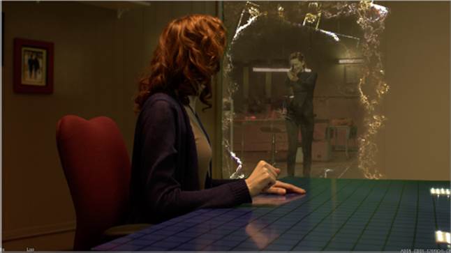
In this chapter, you’ll finish the work you started in Chapter 7. You’ll use the capabilities of the Action node to finish creating the effect of a dimensional doorway opening up between the lead character and her doppelganger from an alternate reality. For those of you who’ve seen “The Place Where You Live” on the web, this is a simplified version of the original effect created by Smoke veteran Brian Mulligan.
1. First, duplicate the Opening Scene C07 sequence you completed in Chapter 7, and rename it Opening Scene C09.
2. Open this new sequence, and press Shift+Z if necessary to fit the entire sequence into the available width of the timeline.
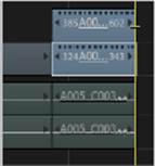
3. Turn the Link button off, and Command+click the two superimposed video clips at the very end (see Figure 9.1).
Figure 9.1 Selecting the last two composited clips to create a ConnectFX effect
4. Click the FX button, make sure the Generate Composite check box is turned on, and click Create ConnectFX.
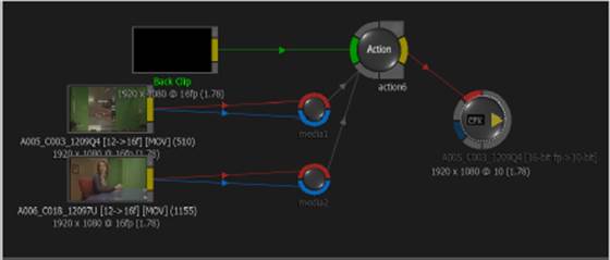
The ConnectFX environment opens up, and a node tree representing the two-clip composite from the timeline appears in the ConnectFX Schematic at the left (see Figure 9.2). If the node tree is offset, you can hold the Control+Command buttons down while dragging within the gray area of the ConnectFX Schematic to pan around, moving the node tree to the center.
Figure 9.2 The ConnectFX Schematic of your two-clip composite
By default, all composites that were originally done using timeline effects are converted to a ConnectFX tree using an Action node. This is because many timeline effects are in fact tools found within the Action node, even though you didn’t know it at the time.
Introducing the Action Node
The Action node is an integrated “compositor within a compositor” that lets you perform more complex multilayer operations than those allowed by the Blend & Comp and Logic Op nodes. Although it’s represented within the ConnectFX Schematic as a single node, this one node actually contains its own Action Schematic, its own bin of Action nodes, and a Media list and Object editor unique to the Action node. Using the Action node, you can do the following:
· Create multiclip composites that go well beyond the Front/Front2/Back inputs of the Blend & Comp node.
· Incorporate color-correction operations, Axis transforms, and Blend mode operations without the need for additional ConnectFX nodes.
· Create more intricate greenscreen keys using the Action node’s Modular Keyer Schematic.
· Transform layers in full 3D space with 3D object support and lighting. (The Blend & Comp node is a 2D compositing operation only.)
· Integrate 3D camera tracking data from other applications.
· Import multilayered Photoshop files.
· Create 3D text objects.
And the list goes on. In short, the Action node is a multipurpose tool for taking care of a wide variety of tasks involving multiple image inputs.
In the following exercises, you’ll use the Action node to finish building the effect of the dimensional doorway, refining the greenscreen work you did in Chapter 7, inserting a fake wall, and building the effect of an energy portal opening up. Before getting started, though, it’s time to take a brief tour of the Action environment so that you can find your way around.
The Action Node Structure
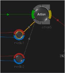
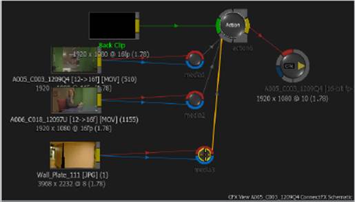
Looking at the Action node, you should notice that it’s different from the other nodes you’ve used in ConnectFX in that it has red and blue media inputs (see Figure 9.3) instead of Front and Back input tabs. It also has a green Back input tab and a yellow output tab that sends both image and matte data.
Figure 9.3 The Action node with two media inputs
Each Action input lets you connect an image for compositing within the Action node. You can select an Action node and press Control+N to add as many inputs as you require to composite however many layers you need. You can connect images of varying resolutions to the different inputs of an Action node.
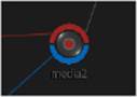
There’s one thing you need to know, however, about the Action node. Each small, round input has separate Front (red) and Matte (blue) tabs, which let you link different images to the Front and Matte of a single media input. For example, you can connect a video clip to the Front and a GMask to the Matte. However, when linking different images to the Front and Matte tabs of a single input, both images need to have the same resolution and the same bit depth. Otherwise, the input will display a red dot (see Figure 9.4), which shows that the two connected images are incompatible.
Figure 9.4 A red dot on an Action input shows that the two images connected to it have different resolutions or bit depths.
If you see a red dot, you can use the internal Resize and RGB LUT controls of the clip nodes to make both images the same. The Resize controls let you change the output resolution, and the RGB LUT controls let you change the bit depth. You’ll see how to do this in one of the exercises later in this chapter.
The Action Environment
To open the Action environment, you can either select the Action node itself or select any of the media inputs. Depending on the last thing you did when working with an Action node, either the Media list or the Object editor will appear.
As important as the Media list is, you’ll also want to open up more panes in the viewport to see the Action Schematic.
1. Choose 4-Up from the Viewport Layout pop-up menu.
2. Click the upper-right pane to select it, and choose Action Schematic from the View pop-up menu. This shows you the node structure that’s internal to the Action node.
3. Select the lower-right pane, and choose CFX Result from the View menu. This shows you the final result of the overall composite, so that you can see what you’re doing within the context of the overall composite. Set the Zoom pop-up menu to Fit.
4. Select the lower-left pane, and choose Action Output1: DefaultCam (or press F4). This option sets the selected viewport to display the output of the currently selected node, letting you see the isolated results of the node on which you’re working.
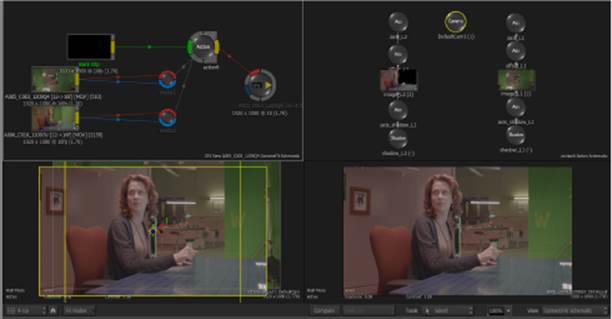
With the viewport set up in this way, it should look something like Figure 9.5.
Figure 9.5 The viewport set to (clockwise) ConnectFX Schematic, Action Schematic, CFX Result, Action Output1: DefaultCam
If you want more room in any pair of panes in a 4-Up viewport, you can position the pointer at the border between any two or at the intersection of all four viewports, and drag to resize them.
The Media List
If necessary, click the Media button to open the Media list, which is the heart of the Action node. While its rows and columns can be a bit daunting to read at first, learning what to look for is key to understanding how the different Action node controls fit together. The Media list displaying the current composite appears in Figure 9.6, and it contains five rows that correspond to each of the Action node’s inputs: B for the green background input tab and two pairs corresponding to the Front and Matte of the media1 (1F and 1M) and media2 (2F and 2M) inputs.
Figure 9.6 The Media list showing a row for every image that’s connected to an input of the currently selected Action node
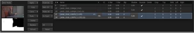
The currently selected media input in the ConnectFX Schematic corresponds to the currently selected rows in the Media list. The Name column shows the name of the image or alpha (A) connected to each input; the K column is used for accessing the Modular Keyer Schematic; the CC column is used for accessing the built-in color-correction controls. Additional columns show the parameters for adjusting X and Y blur, slipping the media forward or back in time, adding a shadow blur, enabling Gaussian blur, dividing a premultiplied image, and cropping the top, bottom, left, and right of an image.
At the left of Figure 9.6, a pair of thumbnails shows the front and matte of the selected rows. To the right of that, a series of pop-up menus and buttons let you copy, paste, and delete media inputs, as well as turn the Front, Back, and Matte on and off.
The Object Editor
Click any node in the Action Schematic to open the Object editor, which exposes the editable parameters associated with the selected node. As with the ConnectFX Schematic, different parameters and controls appear when you select different nodes in the Action Schematic. The layout of these controls will no doubt remind you of the controls found in the timeline Axis control. This is because the timeline effects in Smoke are based on the Action node.
Priority List
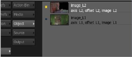
Click the Priority button to open the Priority list, available when the Media list or Object editor is selected. It shows a simple list of every input that’s connected to the Action node. Each input’s position in the list indicates whether it’s in front of or behind other input images; the higher an input is in the list, the farther forward in the composite it appears. In Figure 9.7, you can see that the image of the woman sitting at her desk appears in front because it’s at the top of this list, while the image of the mirror is composited behind this layer since it appears at the bottom of the list.
Figure 9.7 The Priority list in the Action node
Controls at the right (see Figure 9.8) let you reorder each item in the stack to change which clips appear in front of the others. In particular, you can select an item on the list, and use the Bring To Front and Push To Back buttons to move the item in front of or behind other layers in the Action composite. Other commands let you automatically sort the list by each input’s Z-depth (if you’re working with 3D objects and layers), sort the list by objects and GMasks, create groups of objects, and cut, copy, and paste objects in the list.
Figure 9.8 Controls for reorganizing input objects in the Priority list
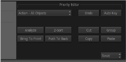
The Priority list is necessary in the Action node because the Media list isn’t organized by priority, and the Action Schematic doesn’t provide a graphical indication of what’s on top. Furthermore, if you begin to arrange layers in space using Z-depth within the Action Schematic, you may experience visual anomalies if the layers in the Priority list don’t match the actual Z-depth of the composite. This is the reason for the Z-Sort button, which automatically sorts the layers in the Priority list based on their Z-depth. The Analyze button automatically keyframes layer order to match animated changes in Z-depth that you create.
The Action Schematic
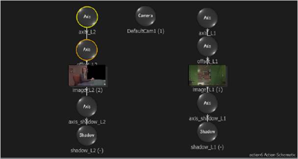
The Action Schematic is a node-based view of the compositing operations within the Action node (see Figure 9.9). It is designed to apply operations to the media inputs, not to determine the hierarchy of composited layers — that’s done with the Priority list. Accordingly, its structure is very different than that of the ConnectFX Schematic. Whereas every node of a process tree in the ConnectFX Schematic is connected, from left to right, in a linear series of sequential operations, the Action Schematic is instead composed of individual, disconnected branches. Right now, there’s one branch for each media input that’s connected to the Action node. Each branch consists of a surface, which represents the image coming in via one of the media inputs, and a number of Axis nodes, which let you transform the surface to which they’re connected in various ways. In the Action Schematic, nodes act upon other nodes.
Figure 9.9 The Action Schematic, cleaned up
Clicking the Action Bin button shows a set of nodes that appear only in the Action schematic. Many of these are nodes that are not available in the ConnectFX Schematic, such as the Texture, Lighting, and Map nodes. Furthermore, the mechanics of working with nodes in the Action Schematic are a bit different, as you’ll see in subsequent lessons in this chapter. For example, Action nodes don’t have either input or output tabs. Instead, links are dragged from within any node to the top of any other node to create a connection.
By default, Action nodes that were automatically generated from timeline effects that were converted into ConnectFX can be a bit messy. You should clean this up before proceeding.
1. Option+drag the top node of each branch of nodes in the Action Schematic to move them together, until they all appear in the available space, as shown in Figure 9.9.
2. If necessary, you can Control+Option+drag to zoom out to create more room and Control+Command+drag to pan around the Action Schematic.
The Modular Keyer Schematic
Click the Media button to open the Media list, and notice that an MK appears in the K column of the 2F and 2M layers. This tells you that there’s a Modular Keyer effect applied to this layer, which is in fact the greenscreen key you created in Chapter 7.
Double-click the MK, and the viewport changes to the MK Schematic, which currently displays a node tree that is the equivalent of the timeline effect you created (see Figure 9.10). This is yet another dedicated environment — one used for creating highly detailed keys using all of the keying tools available in Smoke, including a few not available in other schematics, such as the Matte Blend node for combining multiple Modular Keyer nodes more easily.
Figure 9.10 The automatically created node tree in the Modular Keyer Schematic
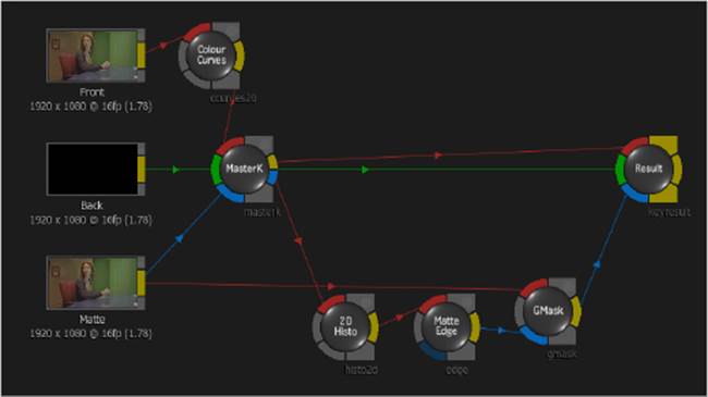
The MK Schematic currently shows a preset node tree that immediately provides most of the tools you’d use to create a highly detailed key, including a Master Keyer node automatically connected to the Front/Back/Matte of the relevant inputs of the Action node; a set of nodes for post-processing the matte generated by the keyer, including the 2D Histogram, Matte Edge, and GMask nodes; and a Colour Curves node preprocessing the Front image before it’s fed into the Master Keyer in case you need to make any color adjustments to improve the key.
The Start Mode pop-up menu provides a way to reset the MK Schematic to different preset node trees that are useful for a variety of keying situations.
To exit the MK Schematic, click the RETURN button.
Node Preferences for Action Nodes
When an Action node is selected, clicking the Node Prefs button gives you access to the resolution and bit depth of that Action node’s internal compositing environment and its CG Rendering, Anti-Aliasing, and Motion Blur settings (see Figure 9.11).
Figure 9.11 The Node preferences of an Action node
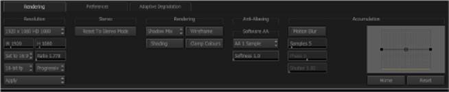
Two other tabs provide access to Action Schematic-specific preferences, as well as Adaptive Degradation settings that let you specify which processor-intensive effects to disable selectively when making adjustments in order to improve interactivity while you work. Click the Node Prefs button again to exit these controls.
Basic Compositing in Action
Now that you’ve gotten the tour, it’s time to dig in and start using these tools to create cinema magic. The following exercises are going to take you through a series of fairly complex operations, so we’ll focus on taking things one step at a time.
Adding a Fake Wall
It’s time to do something about that big hole in the wall to the woman’s left. Eventually, there’ll be a dimensional doorway there, but for now you need to create the illusion that there’s an actual office wall there by adding another clip to the ConnectFX Schematic.
1. Click the Media button to view the Media list while you work.
2. Select the Action node in the ConnectFX Schematic, and create a new media input by doing one of the following:
· Press Control+N.
· Click and hold the New Media button in the Media list above the Front/Matte thumbnails, and choose New Input.
A new input appears, labeled media3. You should also notice that an additional pair of rows appears at the bottom of the Media list with the name colored red to show that they’re disconnected.
3. Scroll down the Media Library, and open up the Office Media and Portal Graphics Elements bins, which contain the additional media elements that you’ll be using for this exercise. Then drag the Wall_Plate_111 clip to the schematic to add it. You may need to zoom out and pan up to create a bit of room in the ConnectFX Schematic.
This is a still photograph of the wall of the set, taken after the shoot, for the express purpose of having a clean plate to use for the doorway opening effect. Of course, it’s the wrong size and has completely different lighting, but you have Smoke, so you can fix that in post.
4. Hold the Option key down, and drag the media3 input to touch the Wall_Plate_111 clip’s yellow output, connecting both the red and blue tabs, as shown in Figure 9.12.
Figure 9.12 Connecting a new clip to the new media input of the Action node to add it to the composite
When you do this, you should notice that the Wall_Plate_111 clip’s name appears in the Name column of the 3F and 3M rows of the Media list. Also, a surface corresponding to the new image should appear within the Action Schematic, with an Axis node automatically attached.
However, looking at the CFX Result pane of the viewport, you can see that the wall graphic is strangely translucent. That’s because this graphic has no alpha channel, so connecting it to the Matte tab of the media input results in its luma channel being used as the matte. This is easily fixable.
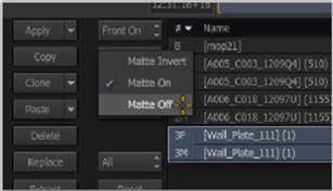
5. With the 3F and 3M layers selected on the Media list, click the Matte Clip pop-up menu (currently set to Matte On), and choose Matte Off (see Figure 9.13).
Figure 9.13 Turning off the Matte input to substitute a solid white matte for the unwanted luma channel matte
Now the wall is solid, but it obscures everything else, which is clearly not the desired effect. As an interesting aside, notice how, by default, lower media inputs have higher priority, appearing higher in the layered composite.
6. Click the Priority button to open the Priority list, then click image1 (currently at the top) to select it, and click the Push To Back button once to move the wall layer between the desk and mirror images. When you’re finished, click the Priority button again to exit.
Now the wall is where it should be, but it’s a bit big relative to the scene, and the amount of visible detail in the image may be at odds with the scale of the rest of the scene.
7. Click the Wall_Plate_111 clip to open its parameters, then click the Resize button, and turn the Active button on. Enabling the built-in Resize parameters inside each clip node fits the Source resolution of the image into the currently specified Destination resolution, using the method selected in the Resizing group of controls.
By default, Resizing is set to Centre/Crop, which crops the clip to fit into the current Destination resolution of 1920×1080 (which matches the resolution of both the project and the Action node). Incidentally, these controls are identical to those found in the Resize node; they’re simply built into each clip node for convenience.
8. Choose Crop Edges from the Fit Method pop-up menu, then adjust the Position and Scale parameters to zoom into the wall image a bit, and slide it up and to the right so that the shadowed part of the wall butts up against the actual wall behind the woman, as shown in Figure 9.14. The settings are Position X −679, Position Y −145, and Scale 86.00.
Figure 9.14 Cropping and resizing the graphic to fit into the composite using the clip node’s Resize controls
At this point, you can see the value of having two viewers: one showing you the output of the currently selected node and the other showing you the final effect. This lets you make adjustments to one node while seeing the final result within the context of the final effect.
Another way of seeing one node while adjusting another is to use the Context option in the viewport. Right-click any node, choose Set As Context, and then set any pane of the viewport to Context 1 (Control+1).
Now for one final bit of housekeeping. As mentioned earlier, there are several operations that require each clip to have matching resolutions and bit depths, and a later exercise uses one of them. For this reason, it’s a good idea to convert preemptively the bit depth of every graphic you import.
9. Click the RGB LUT button, and turn on the Active button. Since the Destination pop-up menu is set to 16 float by default, that’s all you have to do.
As a warning, the RGB LUT settings are deceptive. Even though the Destination pop-up menu is set to 16 float, that doesn’t mean the clip is set to 16 float; you have to turn the Active button on for this setting to take effect.
At this point, the wall is nicely positioned and you’re ready to proceed to the next step of this composite.
Adding a Garbage Matte to the Key
Unfortunately, the positioning of the wall now exposes some problems with your key. In particular, there’s an unwanted intrusion at the top of the fake wall and some noise appearing at the edges of some corners. This can be addressed by improving the greenscreen key you made earlier using the nodes found in the MK Schematic.
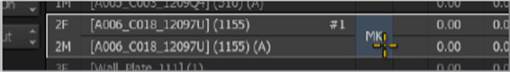
1. Click the Action node to select it, and double-click the MK cell appearing on the 2F and 2M rows of the Media list (see Figure 9.15).
Figure 9.15 Double-click the MK cell to open the Master Keyer Schematic.
2. Choose 2-Up from the Viewport Layout pop-up menu; then click the empty right-hand pane, choose Result from the View pop-up menu (or press 4), and choose Fit from the Zoom pop-up menu. You should now have the MK Schematic on the left and a viewer showing the result on the right.
You may have observed that there’s a magenta cast over the image of the woman at the desk. By default, the Master Keyer (the MasterK node in the schematic) applies spill suppression to eliminate unwanted green fringing in the image. However, the lighting scheme has a lot of greenish yellow, and this suppression is being applied so indiscriminately that it’s necessary to eliminate it. Fortunately, this is easy to do.
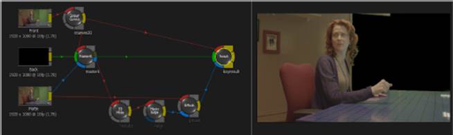
3. Drag a link from the Colour Curves node’s yellow output tab to the Result node’s red input tab, overwriting the previous link (see Figure 9.16). Notice that since the Front image being output from the Master Keyer and the matte being created by the Master Keyer are separate links, you can eliminate the unwanted spill suppression by continuing to use the MasterK node’s matte but applying it to the original image instead of the one output by the MasterK node.
Figure 9.16 Relinking the Front tab from the source image while still using the Matte tab from the MasterK node
Now it’s time to take care of that unwanted bit of hallway at the top of the area reserved for the fake wall using the thoughtfully provided GMask node, which you used in the last chapter.
4. Click the GMask node to open its parameters, and then select the right-hand viewer pane to expose the object controls. Once you select the GMask, the viewer shows the actual matte as a grayscale image where white shows the opaque parts and black shows the transparent parts. You can see that in addition to the ceiling intrusion and fringing, there’s probably a hole around the picture frame at camera left and some holes in the desk. It’s amazing what you see when you take a look at the matte directly.
5. To begin drawing, choose Draw Shape from the Tools menu (or press Shift+C), and then draw a shape that crops out the unwanted ceiling bit and fringing but doesn’t intrude on the area around the woman’s head and hand. Click the first control point you created to draw the shape, and then set the Colour slider to 0 to turn the GMask black, neatly masking all unwanted bits in the key. Since this is a locked shot, drawing the mask is all you need to do. There’s no need to track or animate it.
It can help to zoom into what you’re tracing while drawing a mask by Control+ Option+dragging in a pane of the viewport. You can do this even when you’re in the middle of drawing a shape.
6. Now, to take care of the holes in the desk, create another mask by clicking the Add button, and this time draw a shape that includes the desk, running along the top edge, and surrounds all the parts of the wall that had unavoidable holes from the key. When you’re finished, click the first control point you created to close the shape, and leave this one white, since you’re masking in parts of the matte that you want to stay solid. The result should look something like Figure 9.17.
Figure 9.17 Using the GMask node to create two masks to repair both the transparent and solid areas of the matte
At this point, the matte is good, but, keeping in mind that you originally created a really fast, hard key just to have something for the rough cut, this is probably a good time to revisit what you did to see if it’s possible to refine the key a bit more to retrieve more hair detail. After all, with the ability to use garbage masks to crop out hard-to-key areas, you can key with a lighter touch.
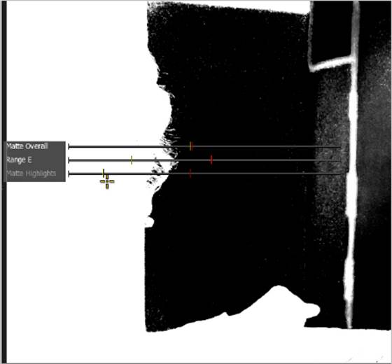
7. Select the MasterK node, then click the right-hand pane of the viewport, and press F4 to toggle to the matte. Zoom in on the woman’s hair, and then hold the Option key down and drag with the pointer in the region around her hair until you see the Matte Overall, Matte E, and Range Highlights sliders. Adjust them to the left or right until you can see all of the fine fringing hair detail overlapping the greenscreen. Hold the Option key down again, drag until you see the Range B and Range D sliders, and adjust them to try to obtain more detail in the hair (see Figure 9.18). You’ll know you’re doing well when you can scrub through the early part of the shot where the woman turns her head and strands of hair don’t seem to disappear. You’ll likely see a lot more fringing in the tougher-to-key parts of the greenscreen material as a result, but that’s okay because you’ll be masking it out using the GMask later on.
Figure 9.18 Refining the Master Keyer matte to retrieve hair detail
8. Select the Matte Edge node, turn on the Blur button, and set Width and Height to approximately 1.08, or just enough to knock the aliasing off the edge.
9. When you’re finished, you may need to select the GMask node and readjust the overlapping garbage mattes to crop out the additional fringing and holes you created when adding back these details in her hair. While you work with the GMask, pay particular attention to the Auto Key button to make sure it’s turned off. This button has a nasty habit of getting turned on when you’re not expecting it, resulting in the automatic creation of keyframes whenever you make an adjustment to a mask. When masking an unmoving subject, keyframes are not necessary.
If you find you’ve accidentally created unwanted keyframes, click the Animation button to open the Keyframe editor, then move the positioner in the timeframe to a frame where your masks are as you want them, and with the proper channels selected in the list on the left, click the Keep button to keep that shape while deleting all other keyframes. Alternatively, you can click the Constant Shape button in the GMask controls to lock the keyframes to the shape at the frame of the positioner.
10. When you’re finished refining the MasterK and GMask node results, click the RETURN button to go back to the Media list.
This key is still pretty harsh, but it’s okay for now. You’ll have the chance later to revisit this composite and redo the keying operation from scratch once you learn more about how to work within the Modular Keyer Schematic.
Simple Color Correction to Match Layers
Now you have a nicer matte and a bright orange wall separating the woman from her evil doppelganger. However, the wall looks ridiculous in its current state; it clearly needs to be color-corrected in order to fit into the environment better and to blend in better with the additional hair detail you retrieved in the previous exercise. Fortunately, the Action node has built-in color-correction tools that you can use.
1. Select the Action node, and then open the Media list if necessary. Select row 3F, and double-click the cell in the CC column to enter the Color Correction editor. The default view of the viewer in the Color Correction editor is Result, which simply shows you the isolated wall. This is no use if you’re trying to match the wall to its surroundings.
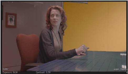
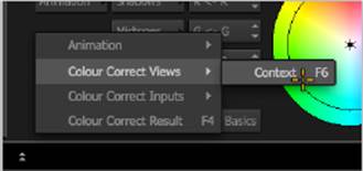
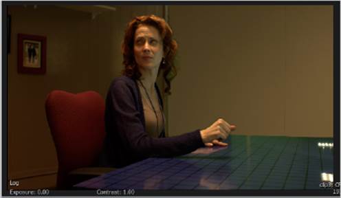
2. Choose Colour Correct Views ![]() Context:defaultcam from the View pop-up menu in the lower-left corner (see Figure 9.19). Now that you can see the overall composite, set the viewer to Log mode so that you can see the scene’s true colors while you grade. You’ll immediately notice that the wall turns a brilliant orange because the wall graphic isn’t log encoded. That’s OK, because you can address this with color correction.
Context:defaultcam from the View pop-up menu in the lower-left corner (see Figure 9.19). Now that you can see the overall composite, set the viewer to Log mode so that you can see the scene’s true colors while you grade. You’ll immediately notice that the wall turns a brilliant orange because the wall graphic isn’t log encoded. That’s OK, because you can address this with color correction.
Figure 9.19 Viewing the layer you’re about to color correct in context
The color-correction controls are fairly standard Offset/Gamma/Gain controls. A set of parameter sliders provides control over image contrast:
Offset Shifts the overall lightness of the image up and down, setting the black point, which is the darkest portion of the image.
Gain Adjusts the brightest part of the picture by setting the white point, stretching the lightness from the white to the black points to fit.
Gamma Redistributes the midtones to make the overall image lighter or darker.
Contrast Stretches or compresses the difference between the lightest and darkest parts of the picture around a central pivot point that’s also adjustable.
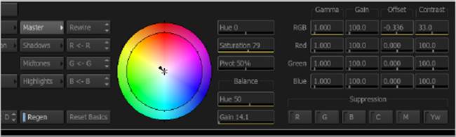
3. Lower the RGB Contrast parameter to the point where the highlight on the wall isn’t glowing horribly (around 33.00). Then lower the RGB Offset parameter until the dark part of the fake wall roughly matches the real wall it’s meant to match (somewhere around−0.336).
Clicking the Master, Shadows, Midtones, or Highlights button to change which zone the color balance affects also changes which zone of the image the Gamma/Gain/Offset/Contrast parameters adjust.
With the contrast of the image adjusted to match, a single color-balance control is used to adjust the color balance in the master, shadows, midtones, or highlights of the image, depending on which button you click.
· Master adjusts color throughout the tonal range of the image, from the darkest through the lightest parts of the image.
· The Shadows, Midtones, and Highlights controls allow for more targeted color adjustments within the darkest, middle, or lightest regions of the image, respectively.
4. With the Master button enabled, drag the color-balance control just a bit toward yellow to add some greenish/yellow to the fake wall that matches the highlights of the wall behind the woman (the color-balance numeric values are represented by Hue around 50 and Gain around 14.1), and then drop Saturation down to around 79. When you’re finished, the settings should resemble those shown in Figure 9.20.
Figure 9.20 Color-correction settings used to match the fake wall to the real one
When the fake wall looks about right, you’re finished. Click the RETURN button to go back to the CFX editor, and your composite in a pane of the viewport that’s set to Log should look something like the one shown in Figure 9.21.
Figure 9.21 The color-corrected wall
Now you’ll probably notice some green fringing in the woman’s hair that wasn’t visible before. Don’t worry about it; it’s something you’ll correct later on.
Building the Door
Now that you have the woman keyed and have replaced the hole in the wall with a convincing-looking wall, it’s time to start putting together the dimensional doorway. The doorway effect itself will be composed of several layers in order to create a more organic sort of effect. The elements you’ll use are particle systems generated in a third-party application, layered carefully to create an animated result.
Cutting a Hole in the Wall
First, you’ll create the basic door shape, with undulating edges created using a single animated movie file positioned to four different locations, using Axis nodes and some Action Schematic trickery.
1. Make some room in the ConnectFX Schematic, open the FX nodes bins, press C to isolate all nodes beginning with C, and drag a Coloured Frame node into the schematic. Then drag in an Action node, press Control+N to add an input, and connect the Coloured Frame node’s yellow output to the media1 input’s red Front tab, leaving the blue Matte tab disconnected.
2. Next, add a 2D Transform node, connecting the Coloured Frame’s output to the 2D Transform node’s red input tab and the 2D Transform node’s yellow output tab to the blue Matte tab of the media1 input, as shown in Figure 9.22.
Figure 9.22 Using a 2D Transform node to create a simple rectangular matte to use with a Coloured Frame
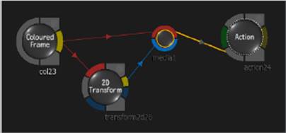
3. Select the 2D Transform node to open its parameters, then turn off the Prop button underneath the Scale sliders, and use the Scale X (set to approximately 32.00) and Scale Y (set to approximately 75.00) parameters to resize the white shape to create a slightly wide doorway shape.
4. Drag the warpline_alpha clip from the Portal Graphics Elements bin of the Media Library into the ConnectFX Schematic, just below the colored frame. Then select the Action node, press Control+N to create a second media2 input, and connect both its red and blue inputs to thewarpline_alpha clip’s output.
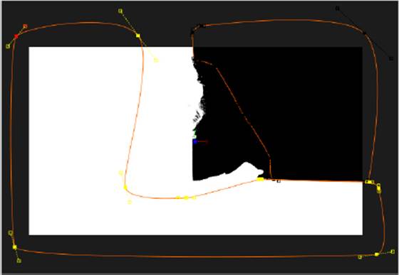
5. With the Action node selected in the ConnectFX Schematic, open the Action bin and double-click the Axis node in the bin three times to add three Axis nodes to the Action Schematic. Drag to move them to each side of the image2 (2) surface node, and then drag a link from the edge of each Axis node to the image2 (2) surface node to connect them, as shown in Figure 9.23.
Figure 9.23 Creating three additional instances of the warpline_alpha animation to use as edges for the doorway
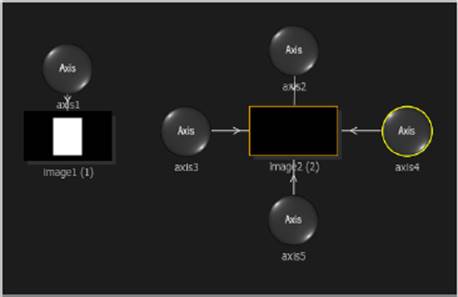
This graphic is an animated edge that you’ll use to eat away at the edges of the white doorway that you’ve created.
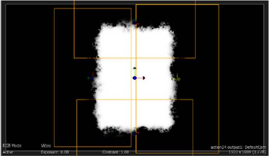
6. The animated edge graphics emerge from nothing in the first frame, so drag the positioner in the timeline to about halfway through the shot in order to see the full graphic, and then double-click the top Axis node in the Action Schematic and set the Blend Mode pop-up menu to Subtract in order to see the warpline_alpha clip as a smoky, ghostlike animation running through the center of the white doorway graphic.
When changing the Blend mode of an image node (sometimes referred to as a surface) that’s being instantiated multiple times by multiple Axis nodes that are connected to it, changing the Blend mode of the single Image node automatically changes them all.
7. Set the proportionally locked Scale parameters to 47 so that the animated graphic is just a little bit wider than the doorway, and then drag the Y Position slider right (or drag it using the viewport layer widget) to move the graphic up to intersect the top edge of the rectangle (around 406). With the Blend mode set to Subtract, the graphic should appear to eat away at the edge of the “doorway.”
8. One by one, select each of the three other Axis nodes you attached to the image2 surface, and adjust their Position X and Y, Rotation Z, and Scale parameters to scale and align each instance of the animated edge along each side of the rectangular doorway, until all four edges are being animated.
9. At this point, the edge of the rectangle may still look a bit hard despite the animated layers subtracting from it, so open the Media list, select row 1F, and adjust the built-in X Blur and Y Blur cells to 22 to feather the edges. This blurring should interact with the animated edges to create a nice, ghostly smokiness, as shown in Figure 9.24.
Figure 9.24 The doorway after layering the warpline_alpha graphic along the edges and using the Media list’s blur function
Building a Dynamic Door Open
Now that you’ve created the ghostly doorway, it’s time to create the effect of it opening, for which you’ll use yet another prerendered particle animation. This time you’ll use a layer that looks like an electrical hole burning open to create the illusion that the doorway is flaring out of nowhere. To make it look even more interesting, you’ll create the effect of three pinholes opening up and merging to create the one doorway using three different instances of a single clip node.
1. Pan down in the ConnectFX Schematic to create more room, and drag the IonSpark clip into the schematic. Open the FX nodes bin, drag an Action node to the right of it, and press Control+N three times to create three media inputs. Finally, connect the Front and Matte tabs of each of the three media inputs to the yellow output tab of the IonSpark clip node, as shown in Figure 9.25.
Figure 9.25 Creating three instances of the IonSpark layer with only one imported clip
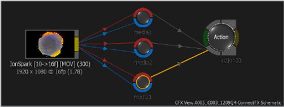
Why connect the IonSpark three times? The answer is that each time you connect a clip node to another media input, you create another instance of that clip that can be composited alongside the others, a duplicate of sorts. The three media inputs then show up as three surfaces within the Action Schematic, each with its own Axis transform attached and ready to go. This is an important technique, because creating three instances of the IonSpark clip using multiple media inputs requires less computer memory than importing three IonSpark clip nodes. It’s the efficient way to work.
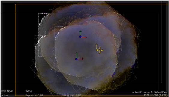
2. Select each Axis node in turn (double-click if the Object editor doesn’t appear), and use the Position X and Y or the onscreen controls in the output1:DefaultCam pane of the viewport to move the three duplicate IonSpark animations into a triangular arrangement, as shown in Figure 9.26. The dark center of each particle system should not overlap with any of the other layers.
Figure 9.26 Arranging the three “burning holes” that will open up to form the doorway
With this arrangement, you’ll animate each Axis node’s Scale parameter to “open” each hole up into the door.
3. Select the first Axis node in the Action Schematic, and then move the positioner to frame 12:31:22+10, when the woman first turns towards the fake wall, and click Set Key to add a keyframe to this frame, freezing its size at 100 percent. Then drag the positioner back to frame 12:31:21+10, where the woman is looking straight ahead, turn on Auto Key, and set the Scale parameter to 0. If you scrub from one keyframe to the next, you should see the animated layer grow from nothing to full size.
4. Select the second Axis node, drag the positioner a few frames past the frame where the first hole is fully open, and click Set Key to create a keyframe to freeze the layer at 100 percent. If you don’t see a Set Key button, open the Animation editor. Now drag the positioner to a few frames past when the first hole opens up, and set the Scale parameter to 0.
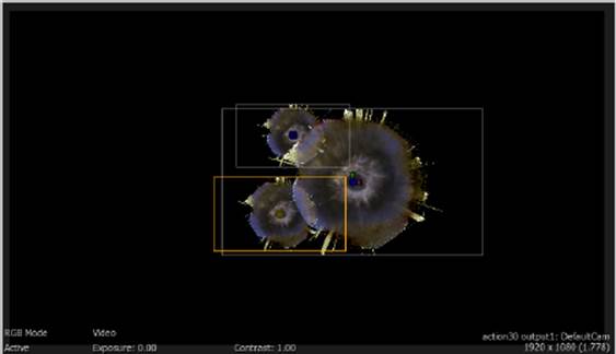
5. Select the third Axis node, and set another pair of keyframes that are slightly offset from the animation of the other two layers to animate Scale from 0 to 100. When you’re finished, each of the three holes should begin growing at a different time, with their start frames offset from one another so that dragging the positioner through the start of the animation shows each hole at a different size, as shown in Figure 9.27. The timing and position of these holes do not have to be exact; they should just look good. When you’re finished keyframing, be sure you turn off the Auto Key button to make sure that you don’t accidentally create unwanted keyframes in other parts of this exercise.
Figure 9.27 The scale of each instance of the hole graphics animated at different times to appear as if they’re opening up
With this set up, it’s time to put the “holes” and “doorway” images together to create the whole doorway effect.
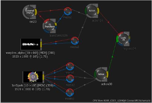
6. Open the FX nodes bin, and drag a Logic Op node into the ConnectFX Schematic between the two Action composites you’ve just created. Connect the “doorway” Action node’s yellow output tab to its red Front input tab, and then connect the yellow output tab of the “holes” Action node to the green Back input tab. The overall node structure should look like Figure 9.28.
Figure 9.28 Putting the whole doorway effect together using a Logic Op node
7. Double-click the Logic Op node to open its parameters, and choose Multiply from the Blend Mode pop-up menu. The Logic Op node is like a simplified Blend & Comp node that combines only two images, but it has a longer list of blend modes from which to choose. Choosing Multiply preserves black wherever it appears in either layer, so that the black border around the door automatically crops the outer edge of the three holes graphics merged together. Now, if you scrub through the timeline, you should see the holes open up and then occupy the shape of the animated door, so that it’s one unified effect (see Figure 9.29).
Figure 9.29 The doorway effect
Why does the Multiply blend node preserve black? Because any pixel’s color value multiplied by zero equals zero, no matter the order of the input layers. Blend modes are all about the math.
Putting It All Together
Now you have a fake wall and a door. It’s time to marry the two together to create the actual effect you’re going for. In the process, you’ll see how you can use two different images as the Front and Matte images of a media input for an Action node.
1. To actually use this graphic to cut a hole in the wall, drag a Negative node from the FX nodes bin into the ConnectFX Schematic, and connect its inputs to the Logic Op node’s yellow output. This creates a suitable matte with a solid border surrounding an undulating region of translucence.
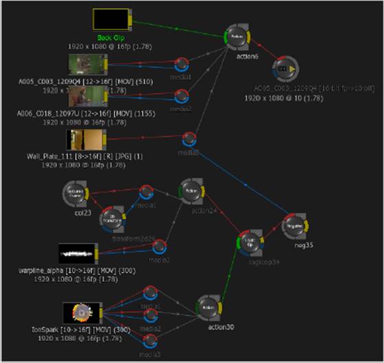
2. Link the Negative node’s output to the media3 input’s blue Matte tab. This works so long as both the Matte image and the Front image have the same resolution and bit depth. The node tree should now look like Figure 9.30.
Figure 9.30 The overall ConnectFX node tree for the doorway effect
3. Nothing happens at first because you’ve disabled the matte for this input, so double-click the original Action node to open its Media list, and with the media3 input selected, set the Matte Clip pop-up to Matte On. You should now see the doorway cutting through the fake wall, although it’s not quite positioned in the right place.
4. Select the 3F/3M rows in the Media list, then open the Action bin, and double-click the Source Matte node to add a surface and Axis specifically to adjust the incoming matte. You may need to Option+drag the top node of this new branch to another location to tidy up the Action Schematic.
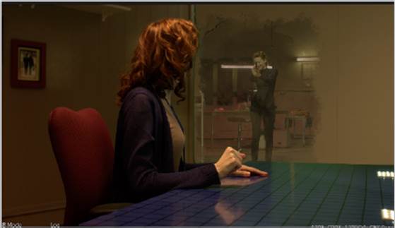
5. Double-click the Axis node that’s attached to the new branch, and adjust the Position X and Position Y parameters to move the doorway to a more suitable position on the wall to reveal the duplicate in the lab at frame 12:31:23+00 (291, 92 is a good coordinate). The result should look likeFigure 9.31.
Figure 9.31 The CFX Result view of the finally positioned doorway cutting through the fake wall, toward the end of the shot
Adding Plasma Shimmer
Well, that was certainly a process! However, you’ve now seen the full power of the Action node for assembling complex 2D composites. Now that you have such a nice effect, it’s time to add just one more effect to put the doorway over the top — some animated crackling and sparking that eats away at the edges of the doorway. In the process, you’ll start to see how accessing different image data at each step of the ConnectFX process tree lets you create additional effects using different aspects of layered images that you’ve already created.
1. Drag an Edge Detect node from the FX nodes bin to the ConnectFX Schematic, and link its Front input tab to the yellow output tab of the Logic Op node. The result should be that the Edge Detect node automatically creates an animated series of outlines tracing the crackly edges of detail from the doorway effect.
2. Select the first Action node, and press Control+N to add one more media input (labeled media4). Connect the Edge Detect node’s yellow output to both the Front and Matte inputs of the media4 input.
3. Select the Action node, open the Priority list, and use it to push this new edge layer back so that it’s between the woman at her desk and the doorway.
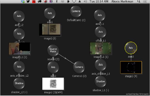
4. It’s in the wrong position, so double-click the Axis node that’s attached to the edge layer in the Action Schematic and use the Position X and Position Y sliders to move the edge layer to overlap the doorway. At this point, the Action Schematic is getting a bit crowded, so don’t forget that you can Option+drag the top node in a branch to move the whole branch to another position in the schematic (see Figure 9.32).
Figure 9.32 Schematic with all layers being composited together
5. With the Axis controls open, choose Add from the Blend Mode pop-up menu to create a hard, electric color interaction, and then raise the Transparency parameter slider to around 43 percent to fade it down to be a little less intense.
6. The resulting “shimmering plasma” effect is a little sharp and harsh, so open the Media list and use the X Blur and Y Blur parameter cells of rows 4F and 4M to blur the edge layer by a value of 1, knocking the edge off of it a little. The end result should look more or less like Figure 9.33.
Figure 9.33 The final effect
Creating ConnectFX Clips
At this point, you’ve got a pretty sophisticated ConnectFX schematic going, but it’s getting a little big. For the very last exercise of this chapter, you’ll learn how to consolidate self-contained sections of a ConnectFX Schematic into a CFX clip, which is essentially a single clip that contains a ConnectFX Schematic inside itself.
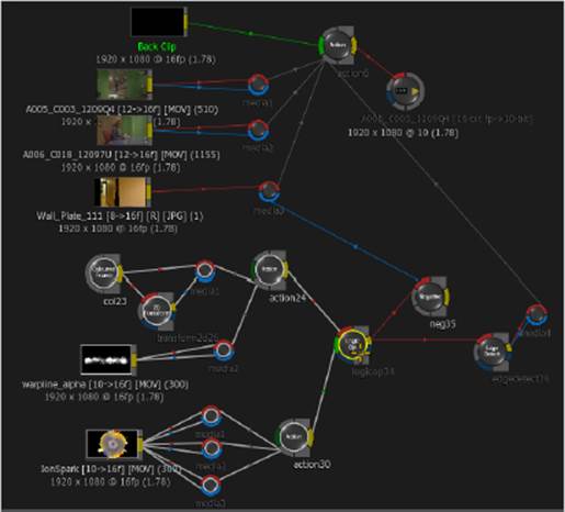
Examining the overall ConnectFX Schematic, you should be able to see that the entire “doorway effect” portion of the tree, up to the Logic Op, is entirely self-contained. In other words, no part of this node tree is connected to any other part, except for the last Logic Op node. This makes this section (shown highlighted in Figure 9.34) an ideal candidate for consolidation.
Figure 9.34 The current state of the ConnectFX schematic, with the doorway effect nodes selected
1. Right-click the Logic Op node, and choose Create CFX from the context menu. A new node is created, labeled logicop34 [CFX]. This node contains both itself and every upstream node that’s connected to the left of it.
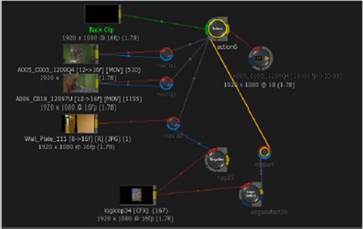
2. To prove this, Shift+click the Logic Op node again to select it and all upstream nodes, and press the Delete key to eliminate them. Then connect the logicop34 node’s yellow output tab to the red Front input tabs of the Negative and Edge Detect nodes, and select the original Action node to see the result. The node tree is significantly smaller, as shown in Figure 9.35, but the end result is the same.
Once the node tree is consolidated, you can open the Timing view, select the ConnectFX clip you’ve created, and click the Render button to render that clip, caching its operations and speeding up your composite’s performance. If you create a ConnectFX clip and then find that you need to modify the composite within it, that’s easy to do.
Figure 9.35 The newly consolidated node tree
3. Right-click the logicop34 node you created, and choose Explode CFX from the context menu. The original node tree should reappear.
The Essentials and Beyond
The lessons in this chapter demonstrate the flexibility that Action adds to the ConnectFX compositing experience. Now it’s your turn to tinker with the composite you’ve created to make it even more interesting.
Additional Exercises
· Adjust the transparency of the doorway using the Colour Correct node that comes before the Negative node.
· Add an Optics node between the mirror layer and the media1 input of the Action node. (Note: You’ll need to add a Coloured Frame node and connect its output to the Optics node’s blue Matte input for this to work.) Experiment and adjust its parameters to create a slightly purplish glow to what appears through the doorway. For added effect, animate the glow to be intense before the doorway opens and less intense as the doorway becomes fully open.
· Add a Deform node after the Optics node to create an undulating warping effect. Reduce the Amplitude parameter until the effect is subtler, and animate the Time Offset parameter to create a sense of motion.
All materials on the site are licensed Creative Commons Attribution-Sharealike 3.0 Unported CC BY-SA 3.0 & GNU Free Documentation License (GFDL)
If you are the copyright holder of any material contained on our site and intend to remove it, please contact our site administrator for approval.
© 2016-2026 All site design rights belong to S.Y.A.