Mastering Autodesk Inventor 2015 and Autodesk Inventor LT 2015 (2014)
Chapter 10. Weldment Design
For this chapter, you must have a good understanding of parts, assemblies, and drawings. You will explore the various aspects of weldment design. Starting from weldment workflows and design methodologies, you'll look at preparations, weld beads, machining features, and weld symbols, as well as how to document the weldment design. You will also learn some tips and tricks along the way.
Weldments are available in the assembly environment as a subtype of the assembly document. Most of the topics in this chapter involve working with assembly files. Therefore, this chapter is not applicable if you have only the Autodesk® Inventor LT™ program installed.
In this chapter, you'll learn to
· Select and use the right weldment design methodology
· Create and edit weld preparations and machining features
· Create and edit different kinds of weld beads, such as cosmetic, fillet, and groove
· Document weldment stages in drawings
· Generate and maintain a consistent BOM across welded assemblies, drawings, and presentations
Exploring Weldment Design Methodologies

One of the basic questions in weldment design is what design methodology should be used to create weldments. Unfortunately, there is no “one-size-fits-all” strategy. The design methodology you use depends on your individual needs and requirements. You will start by defining the different design methodologies:
1. As-assembled A view of the assembly with no weld preparations, beads, or machining features.
2. As-welded A view of the assembly with weld preparations and weld beads but no machining features.
3. As-machined A view of the final welded assembly with the machining features created after the welding had been done. This view includes features that might penetrate or cut through weld beads.
All these represent the various stages in weldment design. Once the weldment design is done, it helps to document the various stages of weldment design in the drawing.
Depending on the need for documentation, interference analysis, mass properties, and other design criteria, you can group the weldment design methodologies into the following four broad categories, which are defined in more detail in this section:
· Part files and part features
· Weldment assembly and derived technology
· Weldment assembly
· Multi-body part files
Part Files and Part Features
You can create a weldment design using part features in part files. With this approach, you use the rich modeling features of the part (sweeps, chamfers, fillets, and lofts) to create a wide variety of weld bead shapes. However, this will be one big mess of a design that has no logical partitions. The main difficulty is creating drawings with different stages—for example, as-assembled, as-welded, and so on—from a single design. You will not be able to see certain edges separating weld beads and components in drawings because they will not even exist (they will be merged out) in the part design. In addition, the bill of materials (BOM) will not list all the individual components needed to assemble the welded structures. Still, this might be an acceptable strategy for small weldment designs that have minor design changes over a period of time. Besides, the assumption is that the designer does not need to create the different stages in design documentation from a single weldment assembly. You could place the part weldment into an assembly and then create presentations and drawings of that assembly. (However, in drawings, you will not be able to create the different stages of weldment design.) Figure 10.1 shows this methodology.
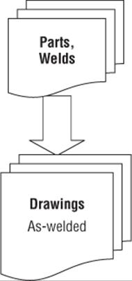
Figure 10.1 Part files and part features
Weldment Assembly and Derived Technology
With this approach, you can derive the weldment assembly (.iam) into a single-part file (.ipt) and model the welds in the derived assembly file using part features. Optionally, you can derive the part file into another part file to show machining on welded assemblies. Disadvantages similar to the ones mentioned in the first method exist; however, you can modify assembly constraints to create variants of weldment assemblies with this approach. The preparations, welds, and machining features will all exist in the derived component files. This might be a good strategy for weldments where a BOM listing is required and there is no need to document different stages of weldment design from a single weldment assembly. Figure 10.2 shows the document layout of this methodology.
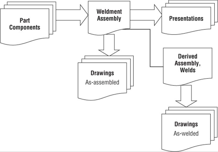
Figure 10.2 Weldment assembly and derived technology
Weldment Assembly
With this approach, you use a mixture of cosmetic, fillet, and groove welds with preparations, machining features, and weld symbols at the assembly level. The main advantage is that the weldment can be documented as-assembled, as-welded, and so on. The BOM outlines the different part components. It does not preclude finite element analysis (FEA), since the weldment assembly can be derived into a part. You might find this approach difficult initially, but you can see large gains in productivity later while documenting the weldment. This is the recommended approach for large weldments that need mass properties, interference analysis, and complete documentation. (Examples are structural frames, piping, industrial gates, fences, and steel furniture.) You can use a combined approach of all four methods if that's what works best for your needs. However, when new enhancements are made to weldments, this approach lends itself to easily leveraging the new functionality. Figure 10.3 shows the document layout of this design methodology. (The figure doesn't show the various subassemblies that the weldment assembly might contain by breaking it into logical pieces.) Good planning helps in generating a well-built design that can be understood and easily maintained by designers. All in all, you should use this design methodology if you cannot decide on one of the other three methods.
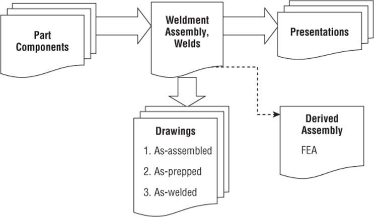
Figure 10.3 Weldment assembly design methodology
Multi-body Part Files
Since a completed weldment exists in a larger assembly as a single component, an interesting way of defining the weldment can be by using multi-body parts. To use this approach, you create separate bodies within the single part file by using the New Solid option in the Extrude, Revolve, and other sketched feature dialogs. This creates a virtual assembly made up of multiple features in a single file. Once the component is defined, it can be divided into an assembly using the Make Components tool as described in Chapter 5, “Advanced Modeling Techniques.” From that point on, you can treat your weldment assembly as though you created it from separate part files from the beginning, with one notable exception: You can then update the assembly and the weldment by editing the multi-body part you created initially. Figure 10.4 shows the layout of the multi-body method.
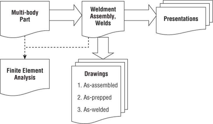
Figure 10.4 Using multi-body part files
You can create a weldment assembly in two ways. For the first method, you create a new weldment assembly by selecting any of the weldment templates provided by the Autodesk® Inventor® software. To do this, just select the Get Started tab, click the New button, and then select an assembly template designated as a weldment template. Or you can convert an existing assembly document into a weldment assembly by selecting the Assemble tab and clicking Convert To Weldment.
Once you convert an assembly into a weldment, it is not possible to convert it into a regular assembly. Also note that in a weldment document, you cannot create new positional representations or use flexible assembly functionality because a weldment is meant to be an assembly of parts fixed in place. Once you've created a weldment assembly, you can go to the next logical step of modeling preparations.
Communication Is the Key to Dealing with Weldments
Depending on your needs, weldments can be as simple as a single part or as complex as assembly weldments with preparations, welds, and machining. Talk to the group that is going to be manufacturing your parts (whether the job is farmed out or in-house) and find out what level of detail the group requires when making the parts to your prints. Often, you will find that what is important to the designer is not as important to the welder (and vice versa). By speaking with these groups, you'll get a better understanding of what path you should take for your weldment models and drawings.
Modeling Preparations
Imagine that you've created the weldment assembly for a boxed container and want to add weld beads. Before adding the weld beads, the assembly needs weld preparations to create space for the weld bead to be placed. You can model a variety of preparation features to mill or remove material. Note that preparations are assembly features only, meaning that these features exist only in the assembly and not at the part level. Here are the most common preparation features:
· Extrude
· Revolve
· Hole
· Sweep
· Chamfer
· Move Face
Figure 10.5 shows the preparation environment and the relevant tools. To create the features in the previous list, you use the same set of steps that you used in part (Chapter 4, “Basic Modeling Techniques”) or assembly modeling (Chapter 8, “Assembly Design Workflows”). The Move Face functionality is primarily intended for weld preparation in the assembly environment and is available in both the part and assembly environments.
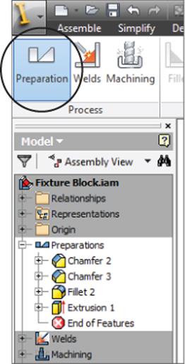
Figure 10.5 Weldment features
Groove welds are classified by the different kinds of weld preparations. Figure 10.6 shows some commonly used weld preparations. In the left column, from top to bottom, you can see the Square Groove, Bevel Groove, and U-Groove types. In the right column, from top to bottom, you can see the Double Bevel Groove, V-Groove, and Double-U Groove types. Observe that these preparations might be referred to by slightly different names in the welding industry. Although most groove welds require nothing more than a simple chamfer, in most cases groove welds require some sort of material-removal preparation.
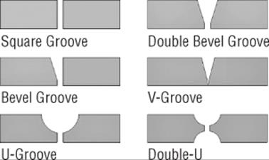
Figure 10.6 Types of weld preparations
The alternative to weld preparation is to build the shape of the preparation using the sketch and then a swept volume (Extrude, Revolve, and Sweep) cut using that sketch to create the feature shape in the part file. However, it is recommended that you use the weld preparation feature, which helps show the manufacturing process. In addition, it aids in documenting the weldment in a drawing with just the components and preparations. Another advantage is that the designer, weld fabricator, or manufacturing instruction–generating program can easily find these features in one place—in other words, in the Preparations folder. This might be useful for generating the desired manufacturing information.
To create a preparation feature, follow these steps:
1. On the Get Started tab, click the Open button.
2. Open the file mi_10a_045.iam from the Chapter 10 directory of your Mastering Inventor 2015 folder.
If you have not already downloaded the Chapter 10 files from www.sybex.com/go/masteringinventor2015, please refer to the “What You Will Need” section of the book's introduction for the download and setup instructions.
3. You have three choices for this step: double-click the Preparations folder in the Model browser to activate the weld bead features, right-click the Preparations folder and select Edit, or click the Preparation button on the Process panel of the Weld tab.
4. Click the Chamfer button on the Preparation And Machining panel and select the bottom edge of the yellow face.
5. Set the chamfer size to 7 mm and click OK.
6. Exit the preparation environment either by clicking the Return button or by right-clicking and choosing Finish Edit.
You can double-click the Preparations folder and edit the individual preparation features as needed. Think of the Preparations folder as a separate environment with its own set of tools. The End Of Features (EOF) node in the browser works differently than the End Of Part (EOP) node in the part modeling browser. In the part modeling browser, when the EOP node is moved around, it sticks at that location even after an update. In the preparation environment, the EOF node can be moved to above or below any feature location in the Preparations folder, just as in part modeling.
However, when you leave the preparation environment—either by double-clicking the top-level assembly node in the weldment assembly or by right-clicking and selecting Finish Edit in the graphics window—the EOF node is rolled all the way to the end in thePreparations folder. It might be thought of as a browser node that does not stick in its dragged browser location, unlike parts. The EOF node has similar behavior whether you are in the preparation, welds, or machining environment.
Once you've placed the weld preparations, you are ready to place welds. Keep in mind that you do not have to create preparations. Also, you can return to the preparation environment even after having placed welds.
Exploring Cosmetic Welds
To create or edit a weld feature, click the Welds button on the Process panel, or right-click the Welds folder in the Model browser and select Edit. You can also double-click the Welds folder and edit the individual features. Figure 10.7 shows the available features in the welds environment.
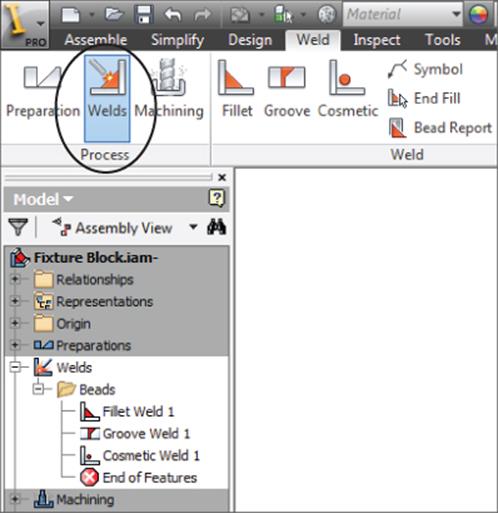
Figure 10.7 Weld features panel
The Cosmetic Weld feature is available by clicking the Cosmetic button in the Weld panel. Figure 10.8 shows the Cosmetic Weld dialog box. When using the Cosmetic Weld feature, you simply select edges of the model. These edges can belong to part components or other weld beads.
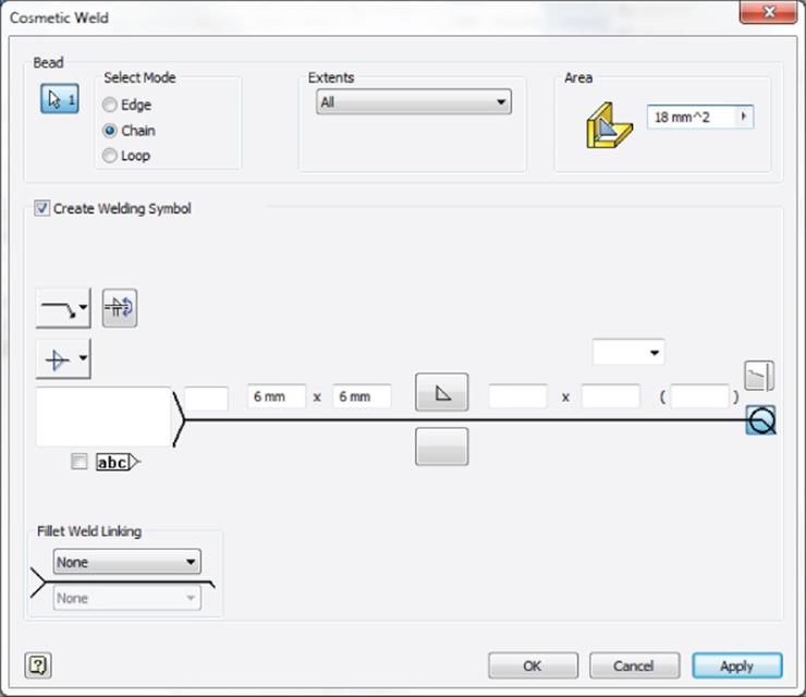
Figure 10.8 Cosmetic Weld dialog box
Cosmetic welds are recommended for use when you have the following conditions:
· A need for lightweight representation.
· No requirement for interference analysis.
· No need for the estimated total mass of the assembly with solid weld beads. However, you could optionally have the cosmetic weld participate in mass property calculations.
Note that the bead (which you define in the upper portion of the weld dialog boxes) and the weld symbol (defined in the lower portion of the weld dialog boxes) are decoupled; in other words, optionally you can create a weld symbol. This applies to all types of weld beads. In addition, you can use a single weld symbol to denote multiple welds involving cosmetic, fillet, and groove welds. Cosmetic welds can represent a wide variety of welds. You can create them using edges (the Edge option), tangent continuous sets of edges (the Chain option), or loops (the Loop option).
Selecting the option of applying a weld symbol will place a symbol on the screen without being prompted for its placement. You can move the symbol after the weld has been added.
Create a Simple Cosmetic Weld
In this exercise you'll create a basic cosmetic weld and a weld symbol by selecting model's edges and entering the specification of the desired weld:
1. On the Get Started tab, click the Open button.
2. Browse for the file mi_10a_001.iam located in the Chapter 10 directory of your Mastering Inventor 2015 folder and click the Open button.
3. You have three options for this step:
· Double-click the Welds folder in the Model browser to activate the weld bead features.
· Right-click the Welds folder and select Edit.
· Click the Welds button in the Process panel of the Weld tab.
4. Once the weld environment is set active by using one of the three methods listed, click the Cosmetic button on the Weld panel.
5. In the Cosmetic Weld dialog box, select the Create Welding Symbol check box (if it is not already selected).
6. Select the Chain option and select the edges as shown in Figure 10.9. The Chain option is similar to the Automatic Edge Chain option in the Fillet dialog box in part modeling. It collects all the tangent continuous edges in a loop on a single face. Note that you may need to use the Select Other tool to toggle through the available loops.
7. Enter 6 mm for both legs in the weld symbol, as shown in Figure 10.8.
8. In the Area input box, enter 18 mm ^2 for the bead cross section based on the leg lengths.
The bead cross section can be calculated using the following equation:
![]()
9. Click the OK button to create the weld and close the dialog box.
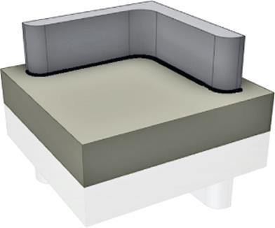
Figure 10.9 Creating a cosmetic weld
The bead cross section area value is critical in determining the mass of cosmetic welds. Later, in the section “Understanding Bead Property Report and Mass Properties,” you'll see how to use this for mass-properties calculations. For now, though, you can close this file without saving changes and continue on to explore more options for the cosmetic weld.
Using Split Faces to Place Cosmetic Welds
In certain cases when there is no edge to click as input, you can split the faces of the components in the part file (.ipt) at the location where it is welded and use the split edges as input to the cosmetic weld feature. On the left of Figure 10.10, for example, there are no explicit edges to click at the intersection of the planar face on the hollow tube and the cylindrical face on the cylinder. Therefore, you could edit the cylindrical part and create a work plane that is offset from the end of the cylinder and then use the Split tool to split the cylindrical face of the cylindrical part with the work plane so that you can use those split edges to create the cosmetic weld feature. The center of Figure 10.10 shows the split edge. Work points cannot be clicked as part of the cosmetic weld feature. The edges need to have finite length in order to be clickable for the cosmetic weld feature.
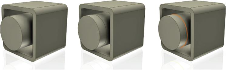
Figure 10.10 Cosmetic welds using split edges
Place Cosmetic Welds with Extents
You can specify extents with parallel planes or planar faces. The extent trims the cosmetic weld bead between the From and To termination planes or planar faces.
To generate the From-To cosmetic weld in Figure 10.11, follow these steps:
1. On the Get Started tab, click the Open button.
2. Open the file mi_10a_002.iam from the Chapter 10 directory of your Mastering Inventor 2015 folder.
3. You have three options for this step:
· Double-click the Welds folder in the Model browser to activate the weld bead features.
· Right-click the Welds folder and select Edit.
· Click the Welds button in the Process panel of the Weld tab.
4. Click the Cosmetic weld tool on the Weld panel. Select the edge shown in Figure 10.11.
5. In the Extents drop-down menu in the Cosmetic Weld dialog box, select From-To.
6. Click the From button and select one of the assembly work planes.
7. Click the To button and select the other assembly work plane.
8. Click OK in the Cosmetic Weld dialog box to create the weld and see the result.
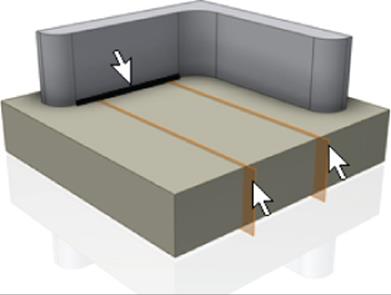
Figure 10.11 Cosmetic welds with extents
Creating Weld Beads
A weld bead feature is a parametric, solid representation of the real-world weld bead. It can be generated from input faces of a single component or from input faces of multiple components, including the faces of existing weld beads in the weldment assembly. You can also create a weld on a single part that is placed in a weldment assembly. Here are some examples:
1. Example 1 Place a single sheet-metal part in a weldment assembly and create fillet welds at flange corners to create a container.
2. Example 2 Create a fillet or groove weld between two plates (two parts or one part that has two extrusion features for the plates).
3. Example 3 Create a fillet or groove weld between two plates and another weld bead.
Weld beads automatically contribute to mass property calculations and can take part in interference analyses. All weld bead features create an independent body that does not take part in Boolean operations with the assembly components. Other machining features can cut into weld beads. There are two major weld features to create physical 3D welds:
1. Fillet Weld Feature A fillet weld builds up corners by adding weld material between faces. Fillet welds are the most commonly used type of weld in industrial machinery. You should use this feature when there is no gap between the components. A specialized kind of fillet weld with a gap is supported.
2. Groove Weld Feature A groove weld feature predominantly fills gaps between components. However, you can also use it when the components are touching each other. There are many opportunities to combine fillet and groove welds to generate the desired weld beads.
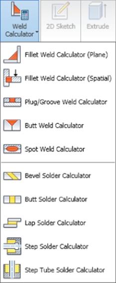
Weld Calculators
The weldment environment also has several weld calculators (only if the design accelerator add-in is loaded). Weld calculators assist you in the design of weld joints. You can check typical welds with different types of loading. You can use these calculators to check static weld loading and to check butt and fillet weld joints for both static and fatigue loading.
Creating Fillet Welds
The basic idea behind a fillet weld is that you are joining two sets of faces. You can control the weld bead definition parametrically by using the parameters shown in Figure 10.12. This is known as leg-length measurement. You can enter the two leg lengths used to generate the bead and also specify the throat measurement. Throat measurement is the distance from the root of the fillet weld to the center of its face. You just enter the throat length, and Inventor calculates the rest of the size of the weld bead. The offset value has relevance only when you declare the weld to be concave or convex. Figure 10.12 shows the two leg lengths and the two types of measurement.
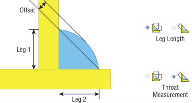
Figure 10.12 Fillet weld definition
The top shape of a fillet weld can be flat, convex, or concave, as shown in Figure 10.13 (from left to right). For flat, the offset is 0.0. For concave or convex based on the offset, Inventor calculates the necessary bump or depression shape.
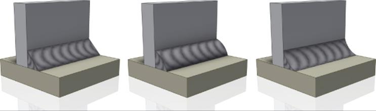
Figure 10.13 Flat, convex, and concave shapes for fillet welds
Modeling a Fillet Weld
Fillet welds are likely the most common weld type you will use in your weldment designs. To create a simple fillet weld, follow these steps:
1. On the Get Started tab, click the Open button.
2. Open the file mi_10a_003.iam from the Chapter 10 directory of your Mastering Inventor 2015 folder.
3. You have three choices here: double-click the Welds folder in the Model browser to activate the weld bead features, right-click the Welds folder and select Edit, or click the Welds button in the Process panel of the Weld tab.
4. Click the Fillet weld tool on the Weld panel. You will see the dialog box shown in Figure 10.14.
5. Enter the leg length value for the Leg1 in the input box as 15 mm. Leg2 is assumed to be the same as Leg1 if the input box is left blank.
6. Ensure that the first Select Faces button (the red arrow) is selected and then click the yellow face.
7. Click the second Select Faces button (or right-click and select Continue) and then click the red face. Note the lightweight weld bead preview, as shown in Figure 10.15.
8. In the Extents area of the dialog, enter 5 mm in the Start Offset box.
9. Click the Direction button on the left of the dialog box to change the start position of the weld bead.
10.Enter 15 mm in the End Offset box and click OK.
11.Locate the Welds folder in the Model browser and expand it to find the Beads folder.
12.Expand the Beads folder, right-click the weld bead found within, and then click Edit Feature.
13.In the Extents area of the Fillet Weld dialog box, click the top drop-down list and change the extents solution from All to Start-Length.
14.Notice that Start Offset remains the same but End Offset is replaced with a length input. You can use this option to specify a known weld length when required.
15.Set the length to 50 mm and click OK.
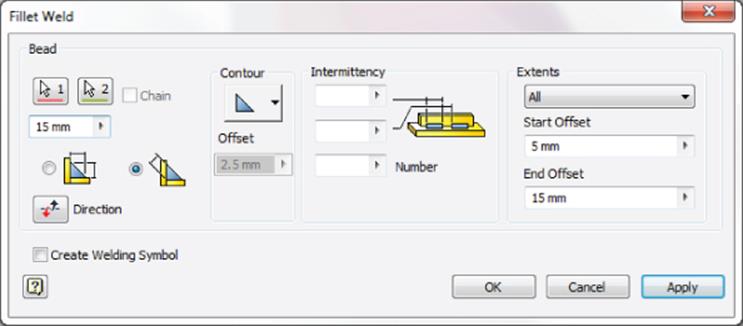
Figure 10.14 Fillet Weld dialog box with start and end offsets
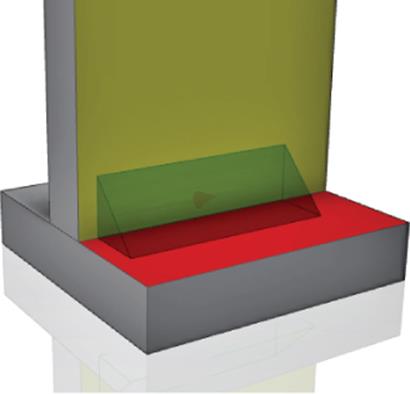
Figure 10.15 Fillet weld preview and fillet weld
This exercise has illustrated a basic fillet weld and some of the extents options available. You can close this file without saving changes and continue reading about other options for placing fillet welds.
Fillet Welds and Gaps
You can place a fillet weld between two parts even if they do not contact, using the fillet weld to bridge the gap. If the goal is to fill the gap, you would likely use a groove weld. Figure 10.16 shows a hole gap through which a cylinder is passing. You can use a fillet weld to bridge the gap, but it will not fill the gap. The fillet weld will work even if the two components are separated by a gap at some places and touch at other places.
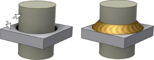
Figure 10.16 Shaft through plate
To create these fillet welds, you still click the two faces, as shown in Figure 10.16. Inventor infers the gap and generates the fillet weld bead. To fill the gap between the two mating faces of components, you should use groove welds.
Figure 10.17 shows another variant of two components that are separated by a gap. Here, the solution is dependent on the size of the weld and the amount of face available. On the left, a 10 mm weld comes up short on the corners. On the right, an 18 mm weld runs past the flat edges of the tube and therefore will not build as selected. The weld adjusts to fit as required. If the weld size is too small to bridge the gap at all or is too large for the selected face, the weld will not be built.
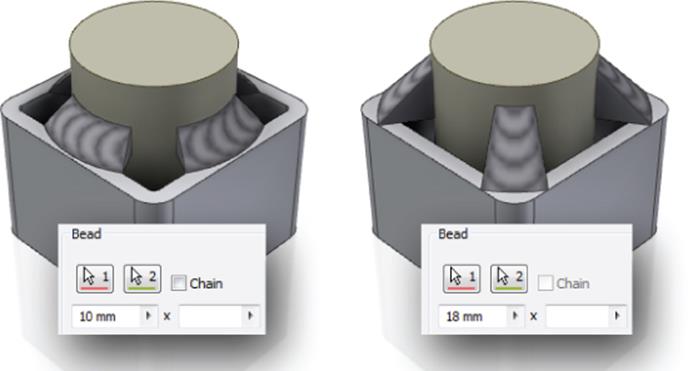
Figure 10.17 Shaft through hollow tube
Figure 10.18 shows a simple gap being bridged with two fillet welds.
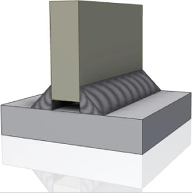
Figure 10.18 Fillet welds across a gap
Don't Forget to Speak with Those Manufacturing the Parts
Inventor provides just about every possible option that you could want as a designer with regard to weld sizes, shapes, and contours. However, you should always speak with those who will be manufacturing the parts to determine whether what you have designed can be built efficiently. It would be unfortunate to spend a lot of time with specific contours, sizes, and finishes if the weld shop is just going to give you a standard fillet weld regardless of the details you call out. You'll need to decide whether it's time to find a new welder or whether you are putting too much information into the part. More than one designer has found this out the hard way when that $10 bracket suddenly ends up costing $100 because of the demanding weld callouts placed on the print.
Creating Intermittent Fillet Welds
Intermittent fillet welds essentially produce patterns of the weld bead along a set of edges. Figure 10.19 shows an example of an intermittent fillet weld using the Start-Length extents solution to adjust the orientation to avoid interference with the existing holes.
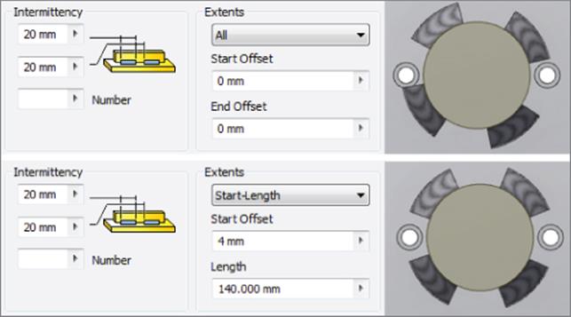
Figure 10.19 Intermittent ISO fillet weld
There are three ways that intermittent welds can be specified, depending on which standard you are using. To change the standard, select the Tools tab and click the Document Settings button. From there you will see the Default Standard setting on the Standard tab. Here is a list describing the differences, as shown in Figure 10.20:
1. ANSI Standard Specify bead length and the distance between bead centers.
2. ISO, BSI, DIN, and GB Standards Specify the bead length, the spacing between beads, and the number of beads.
3. JIS Standard Specify the bead length, the distance between bead centers, and the number of beads.
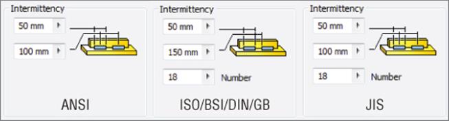
Figure 10.20 Intermittent fillet weld parameters
The Extents control allows you to select the beginning and ending planar faces or planes between which the weld bead will be created. The steps to produce a From-To fillet weld bead are similar to the steps outlined for extents and cosmetic welds earlier in this chapter. When you're welding a long piece of metal, often intermittent welds are cost effective and reduce warping in the part.
Creating Groove Welds
A groove weld is primarily used to fill gaps between two sets of faces. Once such gaps are filled, you might top the groove weld with a fillet weld. Figure 10.21 shows some examples.
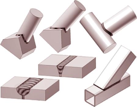
Figure 10.21 Groove weld examples
Like a fillet weld, a groove weld needs two sets of facesets. The Full Face Weld option, when selected, tells Inventor to use the full face to generate the weld. When this option is not selected, only a portion of the face will be used to generate the weld. Inventor calculates the specific portion of the face by projecting the smaller faceset to the larger faceset (if the two facesets are the same size, Inventor picks one of them to project). Figure 10.22 shows the resulting weld beads with Full Face Weld off (left) and on (right).
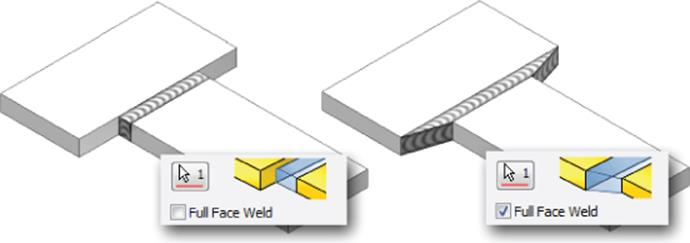
Figure 10.22 Full Face Weld option
The Ignore Internal Loops option controls whether to ignore or consider the internal loop to generate the weld bead. When selected, it results in a “solid” weld bead (Figure 10.23, left); when it's not selected, the result is a “hollow” grove weld (Figure 10.23, right).
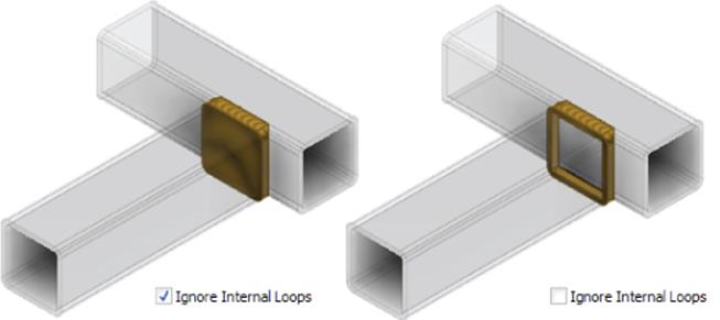
Figure 10.23 Ignore Internal Loops option
The fill direction is used to project one set of faces to another to generate the groove weld bead. In Figure 10.24, you can see the difference between the resulting weld bead shapes.
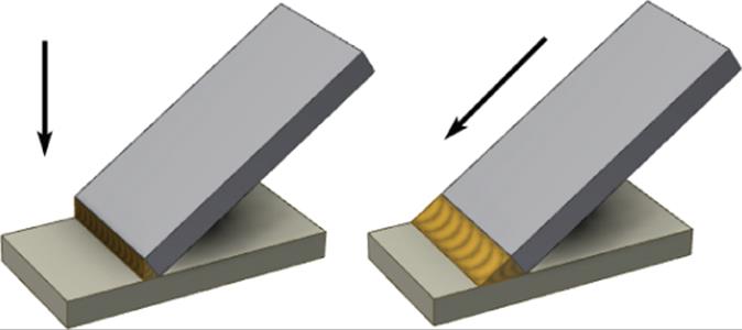
Figure 10.24 Fill direction
Be aware that the Fill Direction option is not available when you use the Full Face Weld option for both faceset 1 and faceset 2 or when using the Radial Fill option. When you are using the Fill Direction option, you might observe that Inventor can create welds that are not manufacturable, depending on the direction you choose.
You can select the following for the fill direction:
· Planar faces and work planes (specifies the direction normal to chosen face/plane)
· Cylindrical, conical, or toroidal faces (specifies the direction of the surface's axis)
· Work axes
· Linear part edges
One question that comes up frequently is, what direction should be selected for the fill? One guideline you can use is to imagine the average geometric center of faceset 1 and the average geometric center of faceset 2. The line connecting the two geometric centers will be the fill direction to generate the groove weld bead. You are not required to calculate the geometric centers of the facesets. It is advisable to try different fill directions to get the desired weld bead shape.
You can use the Radial Fill option to project the weld bead around a curve. When you're using the Radial Fill option, the Fill Direction option is not available. Figure 10.25 shows a radial-filled groove weld.
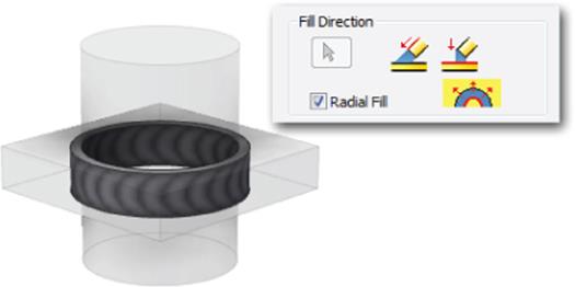
Figure 10.25 The Radial Fill option
To create a simple groove weld, follow these steps:
1. On the Get Started tab, click the Open button.
2. Open the file mi_10a_004.iam from the Chapter 10 directory of your Mastering Inventor 2015 folder.
3. You have three options for this step: double-click the Welds folder in the Model browser to activate the weld bead features, right-click the Welds folder and select Edit, or click the Welds button in the Process panel of the Weld tab.
4. Click the Groove weld tool on the Weld panel.
5. Select the yellow face for faceset 1 and the red face for faceset 2. Note that you may need to rotate the view to see the red face.
6. Click the Fill Direction button and click the visible work axis or any edge or face that establishes the direction to be the same as the work axis.
7. Select the Full Face Weld option for faceset 1 to extend the weld to cover the entire yellow face. Note that selecting Full Face Weld for faceset 2 does not change the weld since the weld bead already covers the entire face.
8. Click OK; your result should resemble Figure 10.26.
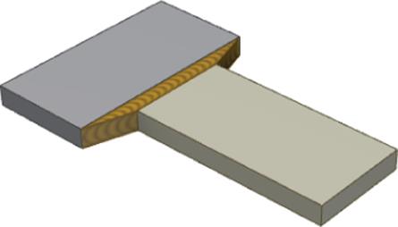
Figure 10.26 Groove weld results
As a general rule, if the preview comes up, it is almost certain that the bead will succeed.
Performing Machining Operations
Once you've created the preparations and welds, you can create machine features. The features available for machining are similar to the features in the preparation environment. In terms of operations, they are performed after the generation of weld beads. One of the main advantages of providing the machining operations in a separate environment is that in drawings you can document them in the as-machined state. Holes and extrude cuts are typical post-weld machining features.
Figure 10.27 shows a welded assembly with machining operations performed on it.
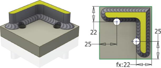
Figure 10.27 Machining features on a weldment assembly
To create the machining features, follow these steps:
1. On the Get Started tab, click the Open button.
2. Open the file mi_10a_005.iam from the Chapter 10 directory of your Mastering Inventor 2015 folder.
3. Double-click the Machining folder in the Model browser to activate it for editing, right-click the Machining folder and select Edit, or click the Machining button in the Process panel of the Weld tab.
4. From the Weld tab, click the 2D Sketch button to create a new sketch.
5. Choose the yellow face to place the sketch and place two hole centers corresponding to the two holes shown in Figure 10.27.
6. Right-click and choose Finish 2D Sketch; then select the Hole feature from the Preparation And Machining panel.
7. Set the hole size to 10 mm and the termination to Through All, and click OK.
8. Right-click and choose Finish Edit (or double-click the top-level assembly in the browser) to exit the machining environment.
Holes that are important to the location of welds should be placed into the parts that are being welded together. Because the machined view of the weldment is a subset of the welded view, you cannot refer to “machined” holes when detailing an as-welded model.
Machining features include, but are not limited to, the following:
· Extrude
· Revolve
· Hole
· Sweep
· Chamfer
· Move Face
Exploring Weld Properties and Combinations
The following sections cover the additional aspects of weldments: setting weld properties, replicating welds, combining fillet and groove weld beads to produce the desired weld bead shape, and using the split technique.
Weld Properties
To turn off the visibility of all weld beads in an open assembly, select the View tab and select Object Visibility ![]() Welds. You can also expand the Welds folder in the Model browser, right-click the Beads folder, and then deselect Visibility to turn off the weld beads of a particular assembly or subassembly. You can suppress individual weld bead features in the Model browser; the suppress feature is similar to part feature suppression.
Welds. You can also expand the Welds folder in the Model browser, right-click the Beads folder, and then deselect Visibility to turn off the weld beads of a particular assembly or subassembly. You can suppress individual weld bead features in the Model browser; the suppress feature is similar to part feature suppression.
You can choose the weld material during the initial conversion of an assembly to a weldment or change it after the fact. Welded Aluminium-6061 is the default material in the Weld Bead Material drop-down list in the Convert To Weldment dialog box, as shown inFigure 10.28. To change it after the fact, you can right-click the Welds node in the browser and choose iProperties. Then select the Weld Bead tab of the iProperties dialog box.
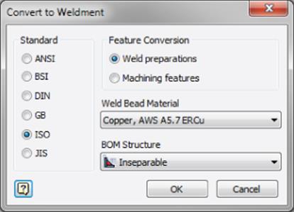
Figure 10.28 Specifying a custom weld bead material in the Convert To Weldment dialog box
In existing weldments, you can change the weld color styles using the weld properties. In the Model browser, right-click the Welds node, select iProperties, select the Weld Bead tab, and choose the weld bead color style or the end fill color style. You can use the weld bead color style to assign different color styles to the weld bead. Similarly, the end caps (faces) that you selected in the weldment assembly can be assigned an end fill color style.
Replication
Welds (cosmetic, fillet, and groove beads) can be copied or mirrored in assemblies through the Copy Components and Mirror Components tools. Both sets of components that support the weld need to be copied or mirrored for the welds to be copied or mirrored. For example, if a cosmetic weld exists only on component Plate1, and if Plate1 is copied or mirrored, the cosmetic weld is also copied or mirrored. You cannot copy or mirror the weld without its components being copied or mirrored. Weld beads can be derived from the assembly into another part document using the Derived Component tool in parts.
Groove and Fillet Weld Combinations
Most welds can be generated using a combination of groove and fillet welds. Figure 10.29 shows an example of welding two hollow tubes with a groove weld. The horizontal tube is welded with a vertical tube. Faceset 1 comprises the two fillet faces on the horizontal member, and Faceset 2 consists of the single mating face on the bottom of the vertical member. The fill direction is established by selecting a vertical edge or a horizontal face.
Figure 10.29 Generating the groove weld bead
In Figure 10.30, a fillet weld is applied. Faceset 1 is composed of three faces, the top horizontal face and the two corresponding fillet faces, as indicated by the light arrows. Faceset 2 is composed of the three corresponding component faces on the vertical tube, as shown by the dark arrows in Figure 10.30. A second fillet weld would then be generated in the same way on the other side.
Figure 10.30 Generating the fillet weld bead
Split Technique
Since welds work on input faces (the two facesets that you select to do the weld), it is sometimes required and at other times desirable to split the input faces in order to have the weld bead only on a certain portion of the face or to have better control of the resulting weld. Essentially, you are helping Inventor use the partial face that is generated from the split.
In certain situations, using fillet welds that involve multiple possibilities might make it difficult to control the placement of welds. One instance of this is when controlling the offset of welds around a cylindrical face. Figure 10.31 shows the difference between using a cylinder with a split face and one without. If the cylindrical face is split, you can place the weld in two parts and control the start and end offsets so that holes are given proper clearance. If the face is not split, Inventor automatically breaks the weld where it encounters the holes, but you can adjust the offsets for the first hole only.
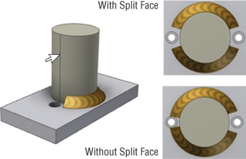
Figure 10.31 Using a split to create multiple fillet welds
In the following steps you will use the Split tool to control the start and stop positions of the weld bead:
1. On the Get Started tab, click the Open button.
2. Open the file mi_10a_006.iam from the Chapter 10 directory of your Mastering Inventor 2015 folder.
Take a look at the existing fillet weld around the blue cylinder. Notice that the offset on the one hole is not adequate. You will create a similar weld on the yellow cylinder but use the Split tool to ensure that you have full control of the offsets.
3. Locate the part called mi_10a_014 in the Model browser and double-click it to set it active for edits (or right-click and choose Edit).
4. Click the Split button under the Combine drop-down on the Modify panel of the 3D Model tab.
5. Select WorkPlane1 from the Model browser for the Split tool.
6. Select the cylindrical face for the Faces selection.
7. Click OK. Note that the cylindrical face is now split into two halves. Figure 10.32 shows the Split selections.
8. Return to the weldment assembly by right-clicking in the graphics screen and choosing Finish Edit.
9. You have three options for this step: double-click the Welds folder in the Model browser to activate the weld bead features, right-click the Welds folder and select Edit, or click the Welds button in the Process panel of the Weld tab.
10.Click the Fillet weld button to bring up the input dialog.
11.Click one of the cylindrical halves for faceset 1.
12.Click the top (red) face of the mating plate for faceset 2.
13.Enter 10 mm for the size.
14.Enter 4 mm in the Start Offset and Stop Offset boxes, as shown in Figure 10.33.
15.Click Apply, repeat steps 11 through 14 to create the other half of the weld, and click OK.
16.Right-click and choose Finish Edit (or double-click the top-level assembly in the browser) to exit the weld environment.
17.Compare the welds you created to the existing weld.
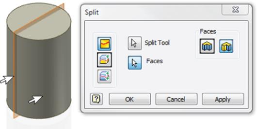
Figure 10.32 Creating a split face in the part
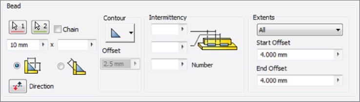
Figure 10.33 Creating a fillet weld with start and end offsets
If you do not want to see the split edges in the weldment drawing, you can turn those edges off individually by right-clicking them in the drawing view and deselecting Visibility, as shown in Figure 10.34.
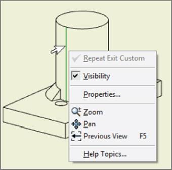
Figure 10.34 Turning off split edges in a drawing
Using the Weld Symbol
You can create a weld symbol in assemblies by clicking the Welds folder and using the Weld Symbol tool. In drawings, you can find this tool in the Annotate tab. You have to decide to create them in the right place (assemblies or assemblies and drawings) based on your communication with the welding department and other departments that are involved in producing the weldment. The weld symbol, which is optional in the assembly environment, has certain key characteristics:
· It cannot be created without a weld bead consuming it.
· The primary bead is the weld bead to which the welding symbol is attached.
· You're allowed to activate the weld symbol grips and reattach the weld symbol to any other visible bead edge from that symbol's group.
· Multiple weld beads (including cosmetic weld beads) can be grouped under a single weld symbol.
· The weld symbols are listed in a separate folder below the Weld Beads folder.
· A bead can be consumed by only one welding symbol object at any given time.
· A linked bead that is moved out of its welding symbol group causes the parent welding symbol to become unassociated.
· Cross-highlighting is supported for both the bead objects and the welding symbol object. If you select a welding symbol node in the Model browser, the welding symbol and all the beads consumed by that welding symbol will be cross-highlighted in the graphics window. Alternatively, if you select a bead node from either the welding symbols portion of the browser or the Beads folder portion of the browser, the bead will be cross-highlighted in the graphics window.
· A new welding symbol can be created for an already created weld feature.
· Welding symbols have visibility control.
· If a weld symbol references a weld feature, then it is consumed. Otherwise, the bead is unconsumed by any weld symbols. Therefore, three browser filtering options are available from the Beads folder context menu: Show All, Show Consumed Only, and Show Unconsumed Only.
Figure 10.35 shows a single weld symbol for the multiple weld beads.
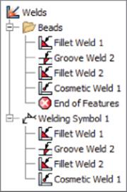
Figure 10.35 Single weld symbol for multiple welds
To add multiple weld beads to the same existing symbol, follow these steps:
1. Right-click the desired weld symbol.
2. Choose Edit Welding Symbol.
3. Add weld beads by selecting them in either the model window or the Model browser.
Only unconsumed weld beads should appear highlighted in the model window. Right-clicking the browser or model window lets you select weld beads and quickly see which weld beads have been unconsumed. To disassociate a weld bead from its corresponding symbol, right-click the bead in the Model browser and choose the Unconsumed Bead tool from the context menu.
Understanding Bead Property Report and Mass Properties
To estimate accurate weld rod usage, fabrication time, and bead weights, the weld property reporting tool is available in assemblies. This can be used to help estimate costs. This tool allows you to query the mass, volume, length, type, and name of individual beads in the assembly. Through an option (available after you select Bead Report from the Weld panel of the Weld tab), you can retrieve this data for the current assembly and all of its child weldment assemblies. This information will be exported to a standard Microsoft Excel spreadsheet, as shown in Figure 10.36. In the weldment workflow, you can generate a weld bead report for the core packaging unit that contains the three subassemblies.
Figure 10.36 Weld bead property reporting in assemblies
To calculate the total length of weld beads, you can sum up the total length using the Excel Sum functions. Length and area values are not reported for groove welds. The default “save to” location is the parent assembly's directory, but you can change this location. Weld properties are, at best, estimates. Many factors can change the weight of a weld bead. If the weight of a part is critical, consider machining the part to meet the criteria after welding.
The cross section entered in the Cosmetic Weld dialog box is multiplied by the length of the cosmetic weld bead and is optionally considered in the mass properties to calculate volume. When the Include Cosmetic Welds option is checked in the Physical tab of the iProperties dialog box, this volume is included in the calculations. The mass is determined by the selected weld material. This option is useful where you need only lightweight representation but at the same time need the welds to participate in mass properties.
Creating Drawing Documentation
The Welding Symbol dialog box, being the same in assemblies and drawings, is specific to the engineering standard you're using. Figure 10.37 shows an example of the Welding Symbol (ISO) dialog box in drawings, and when you hover your mouse pointer over each input control, a tool tip will show its title. Table 10.1 describes what the various controls do.
Figure 10.37 Welding Symbol dialog box in an ISO drawing; see the definitions of the controls in Table 10.1.
Table 10.1 Welding Symbol dialog box controls
|
Control* |
Definition |
|
1 |
Select this option to have the identification line above or below the symbol or to omit it. |
|
2 |
Toggle this to switch the values and options from above the reference line to below the reference line, and vice versa. |
|
3 |
Select this option for fillet weld symbols when they are set on both sides of the reference line. This option includes the following settings: |
|
4 |
Enter a prefix for the symbol, such as depth of bevel, size, and strength, depending on the weld. |
|
5 |
Select this option to specify text to be associated to the welding symbol, such as specification, process, or reference text. The Enclose Text option will enclose the note in a box at the tail of the symbol. |
|
6 |
Use these controls to specify multiple welding symbols attached to a single leader: |
|
7 |
Enter the leg lengths for fillet weld. Other weld types may specify size, depth diameter, and so on, in this area, depending on the type of weld. |
|
8 |
The Symbol drop-down menu lets you select different types of welds, such as V-Groove Weld, Flare-Bevel Weld, Seam Weld, Spot Weld, and so on. If you're using a drafting standard based on ANSI, a secondary fillet-type button can be used. |
|
9 |
Specifies the number of welds, if applicable to the standard. |
|
10 |
Specifies the length of the weld. |
|
11 |
Specifies the contour finish of the weld. Choose from Flush or Flat finish, Convex finish, or Concave finish, or if using the DIN standard, you can choose Toes Blended Smooth. |
|
12 |
Specifies the space between welds. |
|
13 |
Use this option to add the field weld flag to the welding symbol. |
|
14 |
The All Around Symbol toggle allows you to add an all-around symbol to the welding symbol. Note that the GB standard includes a third symbol; all other standards will present a dual-state toggle. |
* Referenced by number in Figure 10.37.
Be Explicit with Symbols
Although you can refer to any textbook on welding for the correct use of the symbols referred to in Table 10.1, keep in mind that many shops have their own “shorthand” versions of weld symbols. It is imperative that you communicate with the welders to make sure you agree on the symbols. Many weld shops do not know the “standard” yet still produce excellent parts.
A perfect example is the “all-around” symbol. Some shops take this to mean only opposite sides of the indicated line, whereas others interpret this symbol to mean you want all contiguous surfaces welded. When in doubt, you should be explicit with your symbols.
Weldment Design Stages
Now that you've explored the tools available in the weldment environment, you'll explore how to document the four major stages of weldment design in the drawing. You can create a weldment drawing in the following stages:
1. Assembly As-assembled with no assembly features
2. Preparation As-prepped
3. Welds As-welded
4. Machining As-machined
Figure 10.38 shows a weldment in the four stages during its creation. Figure 10.39 shows drawing views of the same weldment detailed at the various stages.
Figure 10.38 Four stages of the weldment assembly
Figure 10.39 Four stages of the weldment assembly as drawing views
To create a model state view as shown in Figure 10.39, follow these steps:
1. Create a new drawing from an IDW or DWG template of your choosing.
2. Right-click and select Base View, browse for the file mi_10a_007.iam located in the Chapter 10 directory of your Mastering Inventor 2015 folder, and click the Open button.
3. Back in the Drawing View dialog box, set Orientation to Top.
4. Click the Model State tab and select Assembly, Machining, Welds, and Preparation while watching your view preview. Notice that the view changes for each weldment stage as you select it.
5. Select Preparation and click the drop-down list to explore the options. Note that you can detail each part file individually, showing its preparations clearly without having to perform any extra steps to hide other parts in the assembly.
6. Once you've explored the different model states, click the Display Options tab.
7. Choose Weld Annotations and Model Welding Symbols.
8. Click the screen to set the view.
9. Check to see that your view resembles Figure 10.40.
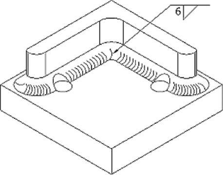
Figure 10.40 A weldment view created with weld annotations and welding symbols turned on
More on Weldment Drawings
You can find more about working with weldment drawings in the section “Working with Weldment Views” in Chapter 12, “Documentation.”
You can also retrieve associative weld symbols from the model by right-clicking the drawing view and selecting Get Model Annotations ![]() Get Welding Symbols. You can retrieve associative weld end fills in the model by right-clicking the view and selecting Get Model Annotations
Get Welding Symbols. You can retrieve associative weld end fills in the model by right-clicking the view and selecting Get Model Annotations ![]() Get Weld Annotations. You can also add nonassociative weld annotations to your drawing. You can create cosmetic weld symbols or weld beads using the Annotate tab by clicking the Welding or Caterpillar tool on the Symbols panel. Figure 10.41shows the annotation retrieval tools in drawings.
Get Weld Annotations. You can also add nonassociative weld annotations to your drawing. You can create cosmetic weld symbols or weld beads using the Annotate tab by clicking the Welding or Caterpillar tool on the Symbols panel. Figure 10.41shows the annotation retrieval tools in drawings.
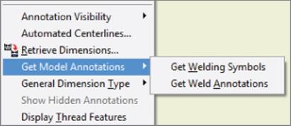
Figure 10.41 Retrieving weld symbols
End Fill
In the Symbols panel, you will see the End Fill tool, which is used to represent seam weld end fills and the gap/groove process shape (concave and convex). Clicking the End Fill tool brings up the End Fill dialog box, shown in Figure 10.42. Note that you can create any weld process shape that is desired in drawings without generating the specified weld in the model.
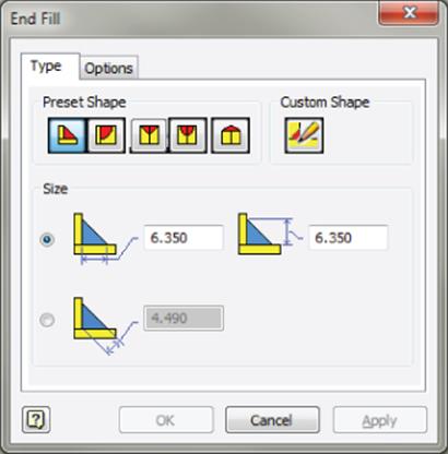
Figure 10.42 The End Fill dialog box
To create a seam weld process shape, follow these steps:
1. Click the End Fill button on the Symbols panel of the Annotate tab (you might need to use the flyout menu to find it).
2. Select the preset shape—for example, Seam Weld.
3. Select two points that represent the shape's arc chord length to create an arc. You can drag above or below the chord line to have the arc above or below.
4. Select the Options tab and select Check Solid Fill.
5. Select a color, such as orange.
In the End Fill dialog box, the fillet process shape has Leg1 and Leg2 as parameters. J-Type, V-Type, and U-Type Preset Shape have controls for the width and depth.
Drawing Weld Symbol
If your assembly has weld beads modeled and weld symbols created in the model, using the Get Welding Symbols option shown in Figure 10.41 is the best way to add weld symbols to the drawing.
If your assembly has weld beads modeled but does not have weld symbols created in the model, you can use the Welding symbol tool and then select a weld bead to retrieve the bead information automatically, based on the information found in the weldment model. However, you should be aware that the symbol won't update if the weld bead is updated in the model.
Many times you may need to just create the weld symbol in the drawing without having to create any weld beads in the assembly. Although this may suffice for your needs much of the time, remember that you cannot perform any interference analysis or mass-properties calculations the way you can with modeled welds.
To create a welding symbol in the drawing, follow these steps:
1. Select the Welding symbol button on the Symbols panel of the Annotate tab (you might need to use the flyout menu to find it).
2. This activates the selection. The command message string displays the text “Click On A Location.”
3. Select a weld bead (if present) or any entity or location in the graphics area to define the location of the welding symbol.
When placing a symbol in the drawing, you can create a complex leader by selecting more than one point as you are placing the symbol. If you would like to add more later, you can do so by right-clicking the existing leader and selecting Add Vertex/Leader in the context menu.
4. Right-click within the graphics area and select Continue from the context menu. The Welding Symbol dialog box appears.
5. Specify the desired welding symbol.
6. The welding symbol preview dynamically updates.
7. Click OK, and the specified welding symbol appears at the specified location.
Caterpillar
You can create and use caterpillars (2D weld representations) in drawings when you want to use a lightweight representation for solid weld beads. As long as the welder is comfortable with this representation, you can use caterpillars. Figure 10.43 shows the dialog box for the Weld Caterpillars tool in drawings. You can create weld caterpillars using the boundary (extent) edges of the welds. This drawing annotation is not associated with weldments in the assembly model. In other words, you can create the caterpillar on any edge without the presence of any corresponding weld bead in the assembly. This is useful when you want to quickly document weld beads in drawings. The caterpillar could be used in addition to the weld symbol to make the documentation better.
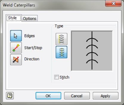
Figure 10.43 Weld Caterpillars dialog box
To create a caterpillar, follow these steps:
1. Select the Caterpillar tool from the Symbols panel on the Annotate tab.
2. Click Edges and select one of the long edges (the lateral edge) of the groove weld.
3. Click Options and enter the Width parameter. Adjust other parameters such as Angle, Arc %, and Spacing.
4. Click the direction to change the shape to concave or convex.
5. The Start/Stop options in the dialog box, which are specified by points, are useful to terminate the caterpillar between the From and To locations. The caterpillar preview shows the effect of changing options.
Figure 10.44 shows the resulting caterpillar for a groove weld.
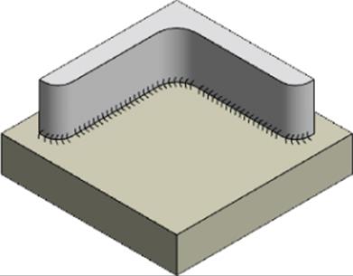
Figure 10.44 Weld caterpillar
Caterpillars can be useful when you want to represent a weldment using a single-part file and create a drawing from it. You can then indicate the position and detail of the welds along the edge. Use the Split tool, which will allow you to create edges where none may exist.

Weldment Workflows
You are a designer working for a company in the packaging industry. The entire packaging system consists of several functional units that form its structure. You are interested in the high-level core packaging unit that consists of three subassemblies: A, B, and C. Let's say it contains parts consisting of a boxed container (A), a lift-arm mechanism (B) for the boxed container, and railings (C) on which the container moves from one station to another. Each subassembly comprises structural steel shapes and/or tubes that are bent and plates that are welded together.
You want to analyze subassembly A, which forms the container in the context of the top-level assembly, to check for interferences. For this, you need accurate solid weld beads to analyze the interference. You want to pattern these solid weld beads and their components and create a drawing of this subassembly. To accomplish this, you would place modeled fillet and groove weld beads.
On subassembly B, which forms the lift-arm mechanism, the weld beads are not very complex, so you don't require a modeled weld for each bead, but you do need mass analysis of welds. In this case, you'll place lightweight, cosmetic welds and document them in the drawing.
On weld subassembly C, which forms the railings on which the container moves, you are interested neither in interference analysis nor in mass properties in assemblies. For C, you are interested only in quickly documenting the weldments in drawings. You need a streamlined interface to document the welds in drawings, and you want to generate any weld bead or symbol regardless of the weld standard. To do this, you will use just the Weld Symbol tool in the drawing environment.
By using the various weld tools in conjunction with one another, you can design and document weldments in a way that makes sense to the task at hand. You can take advantage of the flexibility that comes with using any of these tools together to make weldment design accommodate your specific needs even though they fulfill different design and documentation requirements.
Generating a Bill of Materials and Parts List
Once a weldment design is done, you typically need to generate a bill of materials (BOM) and a parts list. Also, you'll want to customize the BOM to represent a weldment.
You can automatically generate and maintain a consistent bill of materials across welded assemblies, drawings, and presentations. Components that are deemed “inseparable” are assemblies that cannot be taken apart without doing damage to one or more of their components, typically weldments. Manufacturing processes treat inseparable assemblies like purchased components, and they are represented as a single line item.
When documented in its own context, an inseparable assembly is treated as a standard one in that all of the parts are listed. Figure 10.45 shows the BOM for an assembly that consists of a weldment assembly and single-piece part. On the left, the weldment is shown in a structured BOM view, listing the weldment and the parts within. On the right, the BOM is shown as Parts Only; note that the weldments are listed as a single component.
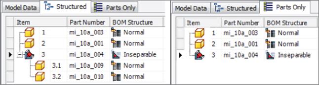
Figure 10.45 Inseparable components as handled by the BOM
To modify the BOM structure, follow these steps:
1. Open the weldment assembly.
2. Click the Bill Of Materials button on the Manage panel of the Manage tab.
3. On the Model Data tab, double-click in the BOM Structure column, select the drop-down for each component, and select Inseparable.
4. Click Done in the Bill Of Materials dialog box.
You can change the BOM structure of several components at once by right-clicking the BOM Structure cell of a component marked as inseparable, right-clicking and choosing Copy, Shift-clicking multiple components, and then right-clicking and choosing Paste.
The Bottom Line
1. Select and use the right weldment design methodology. You've been shown three weldment design methodologies. Before you start on any weldment design, it is imperative to keep the documentation, interference analysis, mass properties, and other design criteria in perspective and select the right design methodology.
1. Master It How do you choose the right weldment strategy for you?
2. Create and edit weld preparations and machining features. Following the weldment methodology, you need to plan on creating the gaps needed (weld preparations) to deposit the weld beads. You need to create post-weldment machining features that go through the weld beads.
1. Master It Weld preparations and machining features are similar to part modeling features. Based on the weld-bead shape needed, you should plan on creating the preparations in advance. Once the welds are done, you must create the features for the machining processes. Where can you find preparation and machining features, and when do you use them?
3. Create and edit different kinds of weld beads, such as cosmetic, fillet, and groove. Weldment design involves the optimal mix of cosmetic and solid weld beads based on the requirements of your design goals and model verification needs.
1. Master It You should create the weld annotations only in drawings, without any need to create them in the model. You have weld subassemblies that need only lightweight representation in both the model and drawings. In situations involving accurate interference and mass properties, you require accurate weld beads. The question is, what type of weld beads should you use?
4. Document weldment stages in drawings. Welds need to be documented in assemblies or drawings. It is important to show the different stages of weldment design in drawings to get a good idea of how to manufacture the weldment. You can use the drawing tools effectively to annotate the welds in drawings. This will help the welder understand the design intent better.
1. Master It Several tools are used for weld documentation. You can annotate the welds in assemblies. If you prefer to document the welds in drawings, you could document the four stages of weldment design: the as-assembled, as-prepped, as-welded, and as-machined stages in drawings. Name two other drawing tools that customize weld documentation.
5. Generate and maintain a consistent BOM across welded assemblies, drawings, and presentations. You have been shown how to generate and maintain a consistent bill of materials for weldment assemblies and a parts list in drawings. Mark parts or assemblies as inseparable to designate them as weldments.
1. Master It How do you generate the BOM and parts list for your weldment?
All materials on the site are licensed Creative Commons Attribution-Sharealike 3.0 Unported CC BY-SA 3.0 & GNU Free Documentation License (GFDL)
If you are the copyright holder of any material contained on our site and intend to remove it, please contact our site administrator for approval.
© 2016-2025 All site design rights belong to S.Y.A.