Mastering Autodesk Inventor 2015 and Autodesk Inventor LT 2015 (2014)
Chapter 11. Presentations and Exploded Views
It is often useful to show an assembly of parts in a disassembled or exploded view for use in assembly instructions, repair manuals, and replacement part diagrams for catalogs. Inventor has a specific environment and file type that allows you to create these views in 3D using the assembly files you've already created. You can even animate the assembly (or disassembly) of your designs and create video files or animated DWF files. Be aware that in order to access the presentation tools, you must be using a full version of the Autodesk® Inventor® program. The Autodesk® Inventor LT™ software does not include the presentation tools.
In this chapter, you'll learn to
· Create an exploded assembly view by creating a presentation
· Create basic linear tweaks
· Create rotational tweaks
· Group, reorder, and animate tweaks
· Publish presentation files
Working in the Presentation Environment
Presentations are generally used to document how an assembly model is put together or taken apart. Your end result could be as simple as a static explosion that you'll use to generate a 2D view in a drawing, or it could be a dynamic video where a design is assembled or disassembled through animation.
To access the presentation tools, you will use a new file template with the file extension .ipn. These are referred to as presentation files in Inventor. When you first create a new presentation file, you'll find that the environment looks similar to the other part and assembly modeling environments, but it has a significantly reduced set of tools. The 3D navigation tools detailed earlier in this book (Orbit and ViewCube® tools), as well as the browser, are used in presentations as well as in the 3D modeling environments. In the following pages, you will create a basic exploded assembly and explore how to create tweaks, animations, and assembly instructions.
Creating a Basic Explosion
In the following sections, you'll take a look at the basics of creating a presentation from an assembly file. This includes accessing an IPN template file, creating an IPN view (explosion), and creating linear tweaks. You'll start by creating a presentation file from a template and then choose an assembly to explode.
If you have not already downloaded the Chapter 11 files from www.sybex.com/go/masteringinventor2015, please refer to the “What You Will Need” section of the introduction for the download and setup instructions.
Accessing an IPN Template
You create presentation files by using an IPN (.ipn) template and then referencing an existing assembly file (.iam). To create this presentation, start with the Standard (mm).ipn template:
1. On the Get Started tab, click the New button.
2. In the Create New File dialog box, select the Metric folder and choose the Standard (mm) .ipn template.
3. Click the OK button.
Figure 11.1 shows the Create New File dialog box and the IPN template.
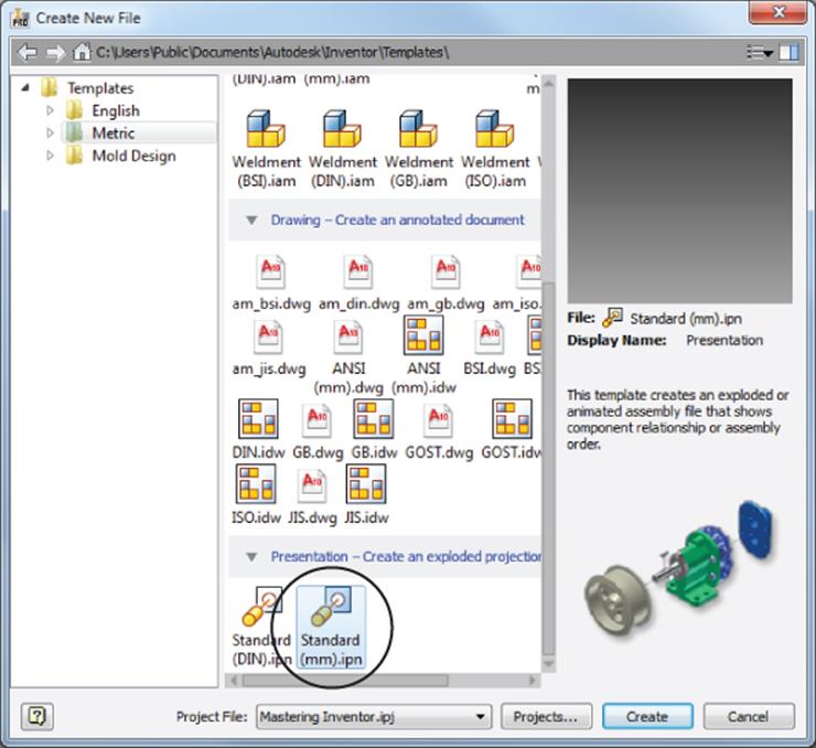
Figure 11.1 Selecting the IPN template
Creating an IPN View
The first step in creating an assembly explosion is referencing an assembly file. A presentation file can reference only one assembly file at a time, but the assembly can be used to generate as many explosions as you might need to properly document your design. For example, you may create one explosion to be used as a 2D drawing view and another explosion to be used as an animation. You may also choose to explode each subassembly in its own explosion. Walk through the following steps to create an assembly explosion:
1. On the Presentation tab, click the Create View button.
2. In the Select Assembly dialog box, shown in Figure 11.2, browse for mi_11a_001.iam located in the Chapter 11 directory of your Mastering Inventor 2015 folder and click the OK button.
3. Click the Options button to specify which view, position, or LOD representation of the selected assembly you want loaded into the presentation environment.
4. Set the view representation to Default and leave the positional and LOD representations set to Master.
5. Click the Associative check box to ensure that the presentation view will update if the assembly view representation is updated.
6. Click the OK button when the File Open Options dialog box looks like Figure 11.3.
If you have a relatively small assembly and it was modeled with a full and robust set of assembly constraints, you may choose to create an automatic explosion in the Select Assembly dialog box and then make minor modifications to meet your needs. In most cases, though, you'll use the manual method.
7. Ensure that the Manual option is selected.
8. Click the OK button.
9. Locate Explosion1 in the Model browser and click the plus sign to expand it so you can see a list of all the components in the assembly, as shown in Figure 11.4.
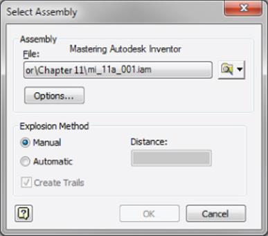
Figure 11.2 The Select Assembly dialog box
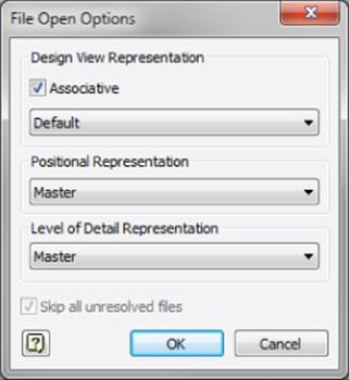
Figure 11.3 The File Open Options dialog box
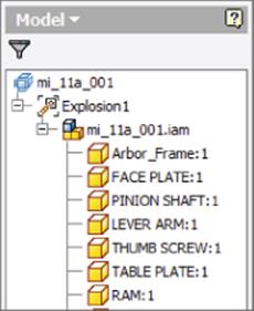
Figure 11.4 Explosion1 in the newly created presentation file
Creating Linear Tweaks
You'll now see the selected assembly (an arbor press assembly) in your presentation graphics area. It's time to start adding tweaks to move or explode the assembly components. A tweak is simply a stored movement vector for a selected set of one or more components. You can define both linear tweaks that move in an x-, y-, or z-axis and rotational tweaks that rotate around those axes. In the next steps, you'll create a linear tweak by first establishing a move direction, choosing a component to move, and then setting the move distance:
1. Click the Tweak Components button on the Presentation tab.
2. In the resulting dialog box (shown in Figure 11.5), ensure that the Direction button is enabled.
3. Select the yellow face of the faceplate to define the direction of the tweak.
Note that the Components button in the dialog box is now enabled and ready for you to select the components to be moved.
4. Select the component with the yellow face (FACE PLATE) and all four of the components named CAP SCREW. Do this either in the graphics area or from the browser, as shown in Figure 11.6.
More on Selecting Components
If you select extra components by accident, simply hold down the Ctrl key and click them again to remove them from your selection set.
If you would like to select an entire subassembly, you must select it from the Model browser rather than the graphics area, unless you change your selection filter.
5. Specify the tweak vector by choosing the Z button in the Transformations area of the dialog box (if it is not already selected).
6. Click somewhere in an empty space of the graphics area and drag your mouse pointer in the positive Z direction (pull toward the lower left of the screen).
7. Note the tweak distance reported in the dialog box as you drag. Enter 100 mm in the dialog box.
8. Click the green check mark to set the distance.
9. Hold down the Ctrl key and click the FACE PLATE component to deselect it. Check the browser to ensure that it is deselected.
10.You'll create a tweak for just the cap screws. This time, rather than clicking in the graphics window, click the triad to select the Z vector and drag the triad to approximately 75 mm.
This simply demonstrates that the triad can be used to tweak components, allowing you to switch directions easily, as opposed to using the buttons in the dialog box to do this.
11.Enter 30 mm in the dialog box and click the green check mark to set the distance. By doing this you have set the tweak to 30 mm even though the initial drag value was approximately 75 mm. Clicking the check mark sets the final tweak value.
12.Click the Close button in the Tweak Component dialog box.
13.On the Model browser, click the Filter button and choose Tweak View from the list.
14.You should see the two tweaks just created listed in the browser, as shown in Figure 11.7.
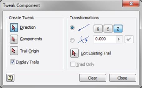
Figure 11.5 The Tweak Component dialog box
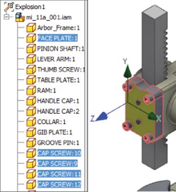
Figure 11.6 Setting the direction and selecting components to tweak
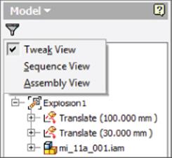
Figure 11.7 Setting the browser to view tweaks
Once you create a tweak or tweaks based on one set of selections and inputs, you can continue to tweak additional components with new selections and inputs by first clicking the Clear button. This allows you to create tweaks quickly without dismissing the dialog box.
Now that you have created a basic linear tweak, in the next section you'll explore how to create more advanced tweaks.
Creating Advanced Presentations
In the following sections, you will look at some of the more advanced functions associated with creating presentations, particularly for use as 3D animations. You will explore how to create rotational tweaks; how to modify tweak trails; and how to group, reorder, and animate tweaks. You'll also discover how to create assembly instructions and publish animations and assembly instructions to a lightweight DWF file that can be easily shared.
Creating Rotational Tweaks
You can add rotational tweaks in much the same way you created the linear tweaks, though rather than indicating the x-, y-, or z-axis for linear direction, you'll use the x-, y-, or z-axis as an axis of rotation and enter the tweak value as degrees of rotation rather than a linear distance. Follow these steps:
1. You can continue using the open file where you left off in the previous section or you can open mi_11a_001.ipn in the Chapter 11 directory of your Mastering Inventor 2015 folder. Click the Tweak Components button on the Presentation tab.
2. In the resulting dialog box, ensure that the Direction button is enabled.
3. Select the shaft of one of the cap screws.
4. With the Components button enabled, select the same cap screw.
5. In the Transformations area of the dialog box, make sure the z-axis button is selected.
6. Switch the radio button to select the rotational option rather than the linear one.
7. Enter 6.25 * 360 in the input box (for six and a quarter revolutions of 360 degrees), as shown in Figure 11.8.
8. Click the green check mark to set the rotation.
9. In the browser, confirm that the tweak is listed.
10.Click Clear to remove the selections and inputs from the dialog box.
11.Repeat steps 3 through 7 for the other three cap screws.
12.Once you've added rotational tweaks for each cap screw, click Close to continue.
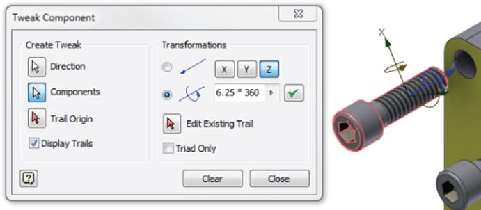
Figure 11.8 Rotational tweak inputs
Creating Tweaks with Drag and Drop
If you're tweaking only one component at a time and you're comfortable with the selection, orientation, and direction behavior, you can establish direction, choose your component, and input the tweak distance all by dragging and dropping the selected component. You can try this with the light blue gib plate:
1. Start the Tweak Component tool.
2. Click the front face of the gib plate, continue holding the left mouse button while dragging the plate away from the main assembly, and then release the mouse button when you've moved it out approximately 45 mm.
Your presentation should look similar to Figure 11.9. You can close this file without saving changes; you will open another IPN file to continue in the following sections.
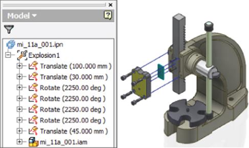
Figure 11.9 Creating tweaks
Understanding Tweak Trails
Trails are added by default. A trail is a line (or an arc in the case of a rotation tweak) that is displayed in the graphics area showing the start and endpoints of a particular tweak. By default, the start and endpoints are defined by the three-dimensional geometric center of all the components that are chosen for a tweak. However, an optional fourth step in the tweak-creation process is to manually select the tweak points by clicking one or more points on each of your selected components. Here are a few more points to know about trails:
· By default, one trail is added per selected component in your tweak.
· Deselecting the Show Trails check box when creating tweaks will turn off the visibility of all tweak trails.
· You can control the visibility of individual tweak trails by expanding a tweak in the Model browser, right-clicking the component name, and choosing Visibility (assuming tweak view is being used).
· You can control the visibility of trails for each component by right-clicking a component and choosing Hide Trails.
· You can edit a tweak by right-clicking the trail and choosing Edit or by clicking and dragging the endpoint of a tweak trail.
· You can delete a tweak or delete a component from a multiple-component tweak by right-clicking the trail and choosing Delete.
· These trails are also visible in drawing views of presentations.
More About Tweaks
Don't forget that the browser filter controls the way tweaks are listed in the browser. When in the assembly view, as you create a tweak a browser node representing that tweak is generated in your browser and nested under the selected components that are part of that tweak.
Editing Tweak Values
In the tweak view, tweaks are listed as line items and the components are nested below them. By selecting a tweak in the browser, you can edit the movement value in the input box that appears at the bottom of the browser. In Figure 11.10, a 45 mm tweak is selected, and a new value of 60 mm has been entered.
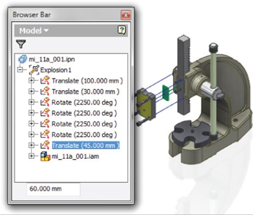
Figure 11.10 Editing tweak values
Adding and Removing Components Used in Tweaks
You can add or remove components from an existing tweak by clicking the Filter button and choosing Tweak View from the list. To remove a component from a tweak, right-click it and choose Delete. This doesn't delete the component from the assembly; it just removes the component from the tweak.
To add a component to a tweak, expand the assembly model tree in the browser, select the component to be added, and then drag and drop it onto the Tweak node in the browser. You'll see a black bar appear in the browser when your cursor is in a valid location.
Create Multiple Views/Explosions
If your assembly is large or complex, consider making several explosions and tweaking only a few components per explosion. You can add explosions by clicking the Create View tool. Each subsequent time the Select Assembly dialog box is shown, however, a new assembly file cannot be specified. You can choose a different view, positional, or LOD representation than you used for your previous explosions. Figure 11.11 shows a presentation with three explosions created. Explosion 3 contains just one Translate tweak, which has been expanded to show the two components involved in that tweak.
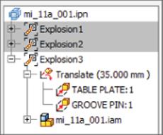
Figure 11.11 Multiple explosions
2 D Presentations Views
If the end goal of your presentation is to create an explosion that looks good in one or more 2D drawing views, then you already know just about everything you need to know, and you never have to use more than the Create View and Tweak Components tools inside the presentation environment. You can learn more about creating views in 2D drawings in Chapter 12, “Documentation.”
Save Camera
Before you save your presentation file and move on to creating a drawing file that uses the exploded view, make sure to set your camera view up exactly as you'd like to see it on the page. Use Zoom, Orbit, and the ViewCube in conjunction with the Precise View Rotation tool to get a view that makes things as clear as possible. Then right-click in the graphics area and choose Save Camera. You can use this saved camera to create a view in the 2D drawing. You can also right-click and choose Restore Camera any time you have changed the camera view, as shown in Figure 11.12.
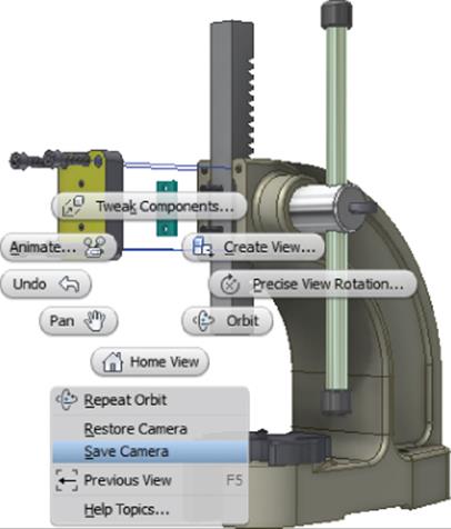
Figure 11.12 Saving a camera view
Understanding Group, Reorder, and Animate Tweaks

You can group and reorder tweaks for the purpose of animating components in a presentation. For instance, in the steps in the section “Creating a Basic Explosion” earlier in this chapter, you pulled the cap screws out all at once and then rotated them one at a time. You may want to have these actions separated, reordered, or grouped in order for them to behave correctly when animated. To see how this works, follow these steps:
1. On the Get Started tab, click the Open button.
2. Browse for mi_11a_002.ipn in the Chapter 11 directory of your Mastering Inventor 2015 folder and click the Open button.
3. If you have zoomed or orbited the assembly, right-click and choose Restore Camera.
4. On the Presentation tab, click the Animate button.
5. In the Animation dialog box, click the ![]() button (at the bottom-right corner) to expand the dialog box so you can view the animation sequence, as shown in Figure 11.13.
button (at the bottom-right corner) to expand the dialog box so you can view the animation sequence, as shown in Figure 11.13.
You'll notice there are currently seven sequence steps. Next, you'll group some of them to reduce the number of sequence steps used.
6. Click the Play Forward button to animate the tweaks; note how the rotation tweaks just spin in place.
7. Click the Reset button.
8. In the Animation Sequence area, hold down Ctrl on the keyboard and select all of the rotation tweaks (2250 deg) and all of the 30 mm tweaks.
9. Click the Group button to group these tweaks into a single sequence step.
10.Click the gib plate and use the Move Up button to change it to sequence step 1.
11.When the gib plate is sequence step 1 and the group of 2250 deg and 30 mm tweaks are sequence step 2, as shown in Figure 11.14, click the Apply button.
12.Click the Play Forward button to animate the tweaks and note that the cap screws now rotate and move at the same time.
13.Click the Reset button and the Cancel button to exit the Animation dialog box.
Note that the Cancel button does not undo the changes you just made and should be labeled Done rather than Cancel.
14.In the Model browser, click the Filter button and choose Sequence View from the list.
15.Expand the Task node to see the sequence steps.
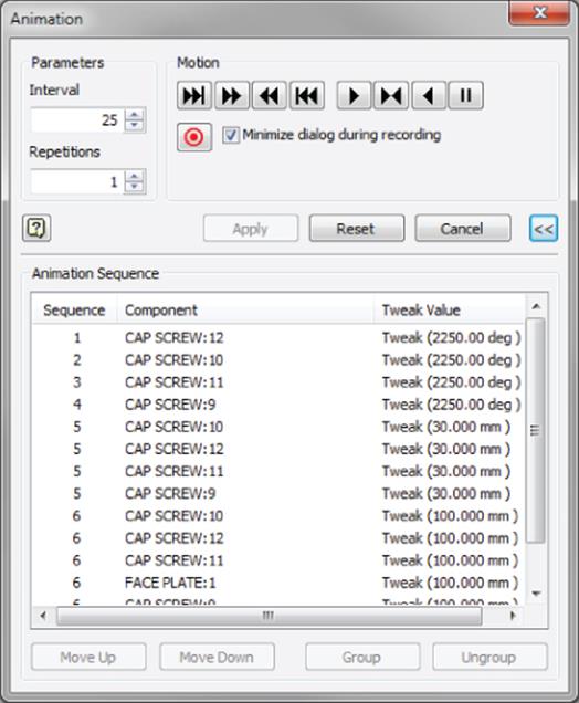
Figure 11.13 Tweak sequences in the Animation dialog box
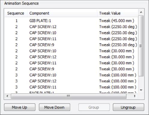
Figure 11.14 Reordered tweak sequence
You'll notice the sequences correspond with the groups you created in the previous steps. This is essentially the same set of steps you saw in the Animation dialog box.
Here are more things to know about working with sequences in the browser:
· You can drag and drop the sequences in the browser to reorder them.
· You can expand the browser node for each sequence to see the list of components grouped in the sequence.
· To remove a component from a sequence, you can right-click it in the browser and choose Delete.
· To remove a component from a sequence and add it to a new sequence, you can right-click it in the browser and choose New Sequence.
Although the rotation of the cap screws is still not true to life in this example, you should be able to see that you can create tweaks in any order you choose and then group and reorder them as required later until you get the result you need. Feel free to experiment with this file to add, remove, group, or reorder tweaks as you see fit to get the screws to rotate and move into place realistically. When finished, you can close this file without saving changes and continue to the next section.

Recording Exploded Presentations
Many design departments use presentations to create short animated movie files to be viewed by the people on the shop floor who assemble the product. You can use the Record button in the Animation dialog box to save an AVI or WMV movie file of your assembly being assembled or disassembled.
Other companies use these tools to record assembly movies for customer support when dealing with replacement part installation, posting them online, or including them on a disc.
When creating movie files in this way, you may find it best to create shorter clips and then use video-editing software (often included with Windows) to put the clips together and add voiceover or text slides.
Creating and Sharing Assembly Instructions
You can create assembly instructions for a presentation animation to share with a customer, to present to a group, or to be used by people on the shop floor. The animations and instructions can be published to a DWF file and viewed with the free Autodesk® Design Review application. Or you can use the .DWFx extension and use Microsoft Internet Explorer as the viewer. Follow these steps to explore how to create assembly instructions:
1. On the Get Started tab, click the Open button.
2. Browse for mi_11a_003.ipn in the Chapter 11 directory of your Mastering Inventor 2015 folder and click the Open button.
3. In the Model browser, click the Filter button and choose Sequence View from the list.
4. Locate Explosion2 in the browser and double-click it to activate it.
Creating Multiple Explosions
Recall that you can create multiple explosions of the same assembly by using the Create View button. Each view becomes a separate explosion with a different camera view. You might show the assembly of external housing components in Explosion1 and then use Create View to create a second explosion. In Explosion2, you can turn off the visibility of the housing components and concentrate on just the internal components. Remember, too, that if you have created view or LOD representations to control the visibility of internal and external parts, you can use them when creating the explosion by clicking the Options button.
You can also copy existing explosions by right-clicking an explosion in the browser and choosing Copy. Then right-click in the IPN filename node (the topmost node) in the browser and choose Paste from the context menu.
5. Expand Explosion2 to see that there are two tasks within it.
6. Double-click Task2a to activate it.
7. In the resulting Edit Task & Sequences dialog box, click the Play button at the top.
8. Click Reset when it is done playing.
9. Click the Play button in the middle to play just Sequence 1.
10.Click Reset when it is done playing.
11.Enter the following into the Description area for Task2a: Assemble collar as shown.
Figure 11.15 shows the Edit Task & Sequences dialog box.
12.Enter 10 in the Interval field to speed up the playback of this sequence.
13.Click Apply.
14.Click the Sequence1 Play button to view the faster playback, and click Reset when finished.
15.Switch the Sequences drop-down from Sequence1 to Sequence2.
16.Note that the instructions have been filled out already.
17.Use the ViewCube, the Orbit tool, or your 3D controller to change the camera view so that you can see the ram and the shaft without obstruction. Zoom in as you see fit.
18.Click the Set Camera button.
19.Click the Apply button.
20.Click the Play button at the top to see the entire Task2a play back again. Note the changes to the camera view you made.
21.Click the OK button.
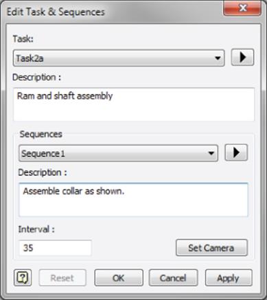
Figure 11.15 Adding assembly instructions
Here are a couple of other actions you can take to organize tasks:
1. Create Tasks When you create tweaks within an explosion, they are initially all created in a single task. To create multiple tasks, use the filter to set the view to sequence view and then right-click an explosion and choose Create Task. Then just drag the sequences into the task as needed.
2. Hide Components You can hide components per sequence by expanding the sequence while in sequence view and revealing the Hidden folder. Then just select the component from the model tree and drag it up into the Hidden folder. If it appears in the Hiddenfolder of a sequence, that component will not be visible for that particular sequence.
If you need to share assembly animations and instructions with someone who does not use Inventor, such as the people on the shop floor, you can publish the presentations to a DWF (.dwf) file:
1. On the Get Started tab, click the Open button.
2. Browse for mi_11a_004.ipn in the Chapter 11 directory of your Mastering Inventor 2015 folder and click the Open button.
3. Click the Inventor button and choose Export ![]() Export To DWF.
Export To DWF.
4. In the Publish Presentation dialog box, select one of the following:
Express Static exploded views are published. BOM data, design views, and positional representations are not published.
Complete The DWF file contains all presentation views, including animations, assembly instructions, and the associated assembly as well as its design views, positional representations, and BOM.
Custom You have full control over which animations and assembly instructions are included or excluded as well as whether to include the assembly, the BOM, and so on.
Figure 11.16 shows the Publish Presentation dialog box.
5. Configure the general options for markup, measure, printing, and password protection.
6. Click Publish.
7. Set the filename and location as you see fit and choose DWF or DWFx for the file type.
8. Click Publish.
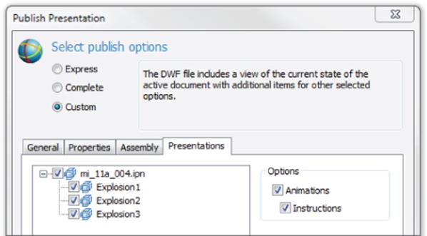
Figure 11.16 Publishing a presentation
The key differences between the two DWF file types is that the 2D DWFx can be read by Windows Vista and XP (with Internet Explorer 7 or newer installed) without the need for an extra viewer such as Autodesk Design Review. 3D DWFx and DWF files still require Design Review. Note too that the DWFx file is generally about twice as large.
You can invite vendors and clients as well as the shop floor to download Design Review for free from the Autodesk website.
Display Published File in Viewer for DWF and PDF
At the bottom of the Publish Presentation dialog box, there is a check box allowing you to choose whether the published file will automatically be displayed in the designated viewer application (typically Design Review for DWF files). Be aware that this option also controls whether PDFs that are generated using Export To PDF are automatically displayed in the designated PDF application. If you'd rather not have Design Review or Adobe Reader open each time you save a DWF or PDF, uncheck this option.
The Bottom Line
1. Create an exploded assembly view by creating a presentation. Presentation files are used to virtually disassemble an assembly so downstream consumers can better visualize the design. The explosion created in the presentation file can be referenced in an assembly drawing to complement nonexploded assembly views.
1. Master It Your assembly design is complex and contains many internal components that can't be visualized in traditional assembly drawing views. What is a good approach to showing those components?
2. Create basic linear tweaks. Tweaks are used to move (or translate) components along a specified axis. This allows you to pull your assembly apart in order to show how it goes together.
1. Master It Your assembly design includes a number of hardware connections, and you'd like to show how they go together in a clear and concise way. How should you do this?
3. Create rotational tweaks. Rotational tweaks allow you to move components in an orientation that is not along the standard x-, y-, and z-axes and that can be used to show rotation of parts for animations.
1. Master It Your assembly has a housing that you'd like to tip out of the way to show both the parts within and the connection features of the housing. When you apply a linear tweak, you can move the housing up and off the assembly to show the parts, but you cannot see the connection features. What do you need to do to see the connection features?
4. Group, reorder, and animate tweaks. Once tweaks are created, you may want to group several of them together into the same sequence of steps and reorder them to show a specific assembly step in an animation.
1. Master It You want to create an animated assembly presentation of your assembly going together, but when creating the tweaks, you did so by going from top to bottom of the assembly rather than following the order in which the assembly would actually take place. Can this be resolved?
5. Publish presentation files. Although you can place views of your presentation file on a 2D drawing, it can be helpful to include the 3D animation for customers and colleagues in the form of a DWF or DWFx file.
1. Master It You want to supply the shop floor with assembly instructions of your assembly going together. What is a good way to do this?
All materials on the site are licensed Creative Commons Attribution-Sharealike 3.0 Unported CC BY-SA 3.0 & GNU Free Documentation License (GFDL)
If you are the copyright holder of any material contained on our site and intend to remove it, please contact our site administrator for approval.
© 2016-2026 All site design rights belong to S.Y.A.