Mastering Autodesk Inventor 2015 and Autodesk Inventor LT 2015 (2014)
Chapter 13. Tools Overview
Using the various Autodesk® Inventor® tools effectively helps you improve your productivity and get the most out of the program. In this chapter you will explore many of the tools that are included with your Inventor installation. Some of these are located within Inventor, and others are external applications. Initially, a certain amount of familiarity is required to be productive with these tools; however, spending the time to become familiar with them pays off in the long run. Most of the topics in this chapter do not apply to the Autodesk® Inventor LT™ program.
This chapter assumes you have a good understanding of parts, assemblies, and drawings. You will learn about the various aspects of Inventor tools and about some of the add-ins. You'll look at the key aspects of the tools and add-ins that come with Inventor as well as relevant workflows. Many other tools can be built using the application programming interface (API). Although the API is not covered in this book, you can find a great deal of information online about using it to develop your own tools.
This chapter covers a number of tools, including the BIM Exchange, AutoLimits, Design Assistant, Drawing Resource Transfer Wizard, style tools, Supplier Content Center, the Task Scheduler, the iProperties tool, the Measure tool, the Customer Involvement Program (CIP), customer error reporting (CER), and more.
In this chapter, you'll learn to
· Take your models from Inventor to the Autodesk Building Systems program
· Create AutoLimits (design sensors)
· Manage design data efficiently using Inventor tools
· Manage styles
· Create expressions with iProperties
· Give feedback to Autodesk
Exploring the BIM Exchange
The Building Information Modeling (BIM) Exchange is an add-in environment for parts and assemblies. Using the BIM Exchange, you can import Inventor models into the AutoCAD® MEP and Autodesk® Revit® MEP products, which are used for building design and construction systems. The MEP products are used to document the mechanical, electrical, and plumbing information of the designs. To access the BIM Exchange environment, you must first have a part or an assembly file open and then select the Environments tab and click BIM Exchange.
Assembly Model Simplification
Typically, when you author an Inventor model for use with a building systems application (such as Revit, for example), you will want to reduce the amount of detail in that model so the file size is smaller and so you are not giving away too much intellectual property. You can start with an assembly file and use the Simplify tools to prepare your model for exporting and sharing with BIM applications. To access these tools, you can click the Simplify tab in the assembly environment, where you will find the following tools:
1. Include Components Use this tool to create a view representation using only the selected components. You can then choose this view representation to create the exported BIM model. For instance, you might use this tool to select only the externally visible components of a condensing unit assembly to prepare it for use in Autodesk Revit MEP. The result would be a new view representation created in the 0Representations folder of the browser and named something like Simple View1. To edit the resulting view representation, you simply right-click it in the browser and choose Edit Include Components.
2. Define Envelopes Use this tool to replace an assembly component with a rectangular or cylindrical bounding box. For instance, you might use this to remove extra detail for components such as fasteners. Defining the envelope of a bolt allows a model to be used for fit checks and sizing where, for example, a protruding bolt head might be important, while at the same time it greatly reduces the number of model faces and edges the component is made up of.
3. Create Simplified Parts Use this tool to create a simplified part file from an assembly view by referencing the current view representation. For instance, if you used the Include Components tool to create a view representation of just the externally visible components of a condensing unit assembly, you could then use the Create Simplified Part tool to combine the remaining visible components into a single part model.
Exploring the Include Components Tool
If you have not already downloaded the Chapter 13 files from www.sybex.com/go/masteringinventor2015, please refer to the “What You Will Need” section of the introduction for the download and setup instructions.
Once you're sure you have the Chapter 13 files in place, follow these steps to see the Include Components tool in action:
1. On the Get Started tab, click the Open button.
2. Browse for mi_13a_014.iam in the Chapter 13 directory of your Mastering Inventor 2015 folder and click the Open button.
3. From the Simplify tab, click the Include Components button.
4. In the tool controls, locate the Select All Occurrences button and click it. When it's selected, you'll see a check mark next to the button, as shown in Figure 13.1.
5. Next, use the browser to locate and select all of the components except the ones named
· mi_13a_Clip
· mi_13a_Washer
6. Once your selection is complete, use the tool controls to toggle the view control to View Excluded. The result should turn off all of the components, except the ones listed in step 5.
7. Use the tool controls to toggle the view control to View All and then click the OK button (the green check mark button) to create the simplified view representation. The results are shown in Figure 13.2.
8. Expand the Representations folder in the browser, if required, and locate the node for the active, simple view representation. It will have a check mark next to it.
9. Right-click the simple view representation and choose Edit Include Components to bring back the Include Components tools.
10.Hold the Ctrl key on the keyboard and click the components named mi_13a_4035 to exclude them from the simplified view representation and then click the OK button in the tool controls to update the simplified view representation. The results are shown inFigure 13.3.
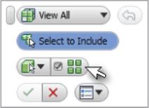
Figure 13.1 The Select All Occurrences button in the tool controls
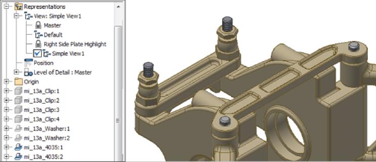
Figure 13.2 The resulting simplified view representation
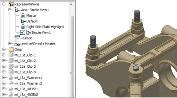
Figure 13.3 The final simplified view representation
In this example, the resulting simple view representation is not really that much simpler, but you've explored the methods used to create and update a simplified view representation using the Include Components tool. You can close the current file without saving changes and continue to the next section.
Exploring the Define Envelopes Tool
The Define Envelopes tool can be used to reduce the number of faces and edges present in an assembly model, which will help reduce the file size of the BIM export version. You can follow these steps to see the Define Envelopes tool in action:
1. On the Get Started tab, click the Open button.
2. Browse for mi_13a_016.iam in the Chapter 13 directory of your Mastering Inventor 2015 folder and click the Open button.
3. From the Simplify tab, click the Define Envelopes button.
4. In the tool controls, locate the Select All Occurrences button and ensure that the check box is selected.
5. Find an instance of the cap screw named mi_13a_4762 and select it.
6. In the tool controls, locate the Bounding Box/Bounding Cylinder control and change it to Bounding Cylinder, as shown in Figure 13.4.
7. Use the grip arrows to adjust the size of the bounding cylinder to your liking.
8. Click the Apply button (it looks like a green plus sign) found in the tool controls to define the bounding envelopes for the screws.
9. Notice that the browser nodes for both of the mi_13a_4762 components are gray, indicating that they have been hidden. And notice, too, that a browser node named Envelope1 has been created to represent the screws.
10.Select one of the mi_13a_Bushing components and set it to use a bounding box and then click the OK button to create the bounding boxes for both bushings, as shown in Figure 13.5.
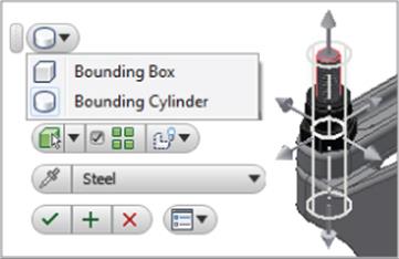
Figure 13.4 Creating a bounding cylinder
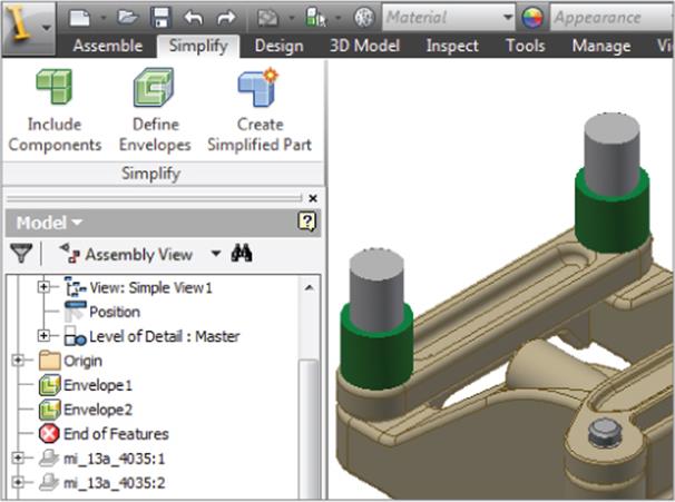
Figure 13.5 The resulting envelopes
You'll notice that a new envelope is created in the browser for the bushing components. If you need to modify the envelope, you can right-click it and choose Edit Envelope, Delete, or Show Original. Feel free to experiment with the Define Envelope tool to see how you can use it to reduce the details of other components in the assembly. When you have finished, you can close the current file without saving changes and continue to the next section.
Exploring the Create Simplified Part Tool
The Create Simplified Part tool can be used to derive the active assembly file into a new part file, using the current view representation and any component envelopes that might be present. You can follow these steps to create a derived part using the Create Simplified Part tool:
1. On the Get Started tab, click the Open button.
2. Browse for mi_13a_018.iam in the Chapter 13 directory of your Mastering Inventor 2015 folder and click the Open button.
3. From the Simplify tab, click the Create Simplified Part button.
4. Use the Combine Style buttons to select a Solid Body style. This option handles how the components of the assembly will be combined as solid bodies in the resulting derived part file. If your goal is to reduce the amount of intellectual property in the file you provide others, you'd want to use the leftmost button to merge the seams between solid bodies and make it more difficult for the file you create to be used to reverse-engineer the design.
5. Enter Simple_mi_13a_018 in the New Component Name input.
6. Accept the default value for the template file or use the Browse Templates button (it looks like a blank sheet of paper) to select a different part file template.
7. Set the New File Location path to the Chapter 13 directory of your Mastering Inventor 2015 folder and then click the OK button. Figure 13.6 shows the Create Simplified Part dialog entries and selections.
8. Examine the browser in the resulting new part file to find the derived assembly node and extrusion features for each assembly-level envelope, as shown in Figure 13.7.
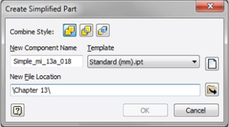
Figure 13.6 Creating a simplified part
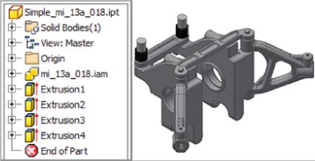
Figure 13.7 The simplified derived part
The simplified derived part behaves the same as any other derived part, which means that edits to the original assembly file are carried through to the simplified part version unless you right-click the derived assembly browser node and choose to suppress or break the link to the base component. Keep in mind that, at this point, your new simplified derived part exists only in the current Inventor session and has not yet been saved to disk. If you'd like to explore the link between the original file and the simplified file, you can save both files now. Otherwise, you can close the current simplified part file and the original assembly file without saving changes and continue to the next section.
Part Model Simplification
In addition to the tools available to simplify assembly models, you can also use the BIM Feature Recognition and Simplify tools in the parts environment to reduce details that are not needed for BIM models, and you can use the Recognize Revit Features tools to make your models friendlier to Autodesk Revit.
Simplify Part Models
One of the issues with handing part models created in Inventor to the BIM user is that the models often contain cosmetic or manufacturing features that are important in the mechanical design but are not required for the BIM layout and planning application. For example, if you create a model of a machined part in Inventor, you will likely need to include and specify rounded edges, holes, and other features as part of the mechanical design. However, these features are not important to the BIM user and can slow down the BIM application. So to help with this, Inventor includes part simplification tools to remove detail and voids, as well as reduce the number of faces and edges in a part model.
You can find the Simplify tools by going to the Environments tab and clicking the BIM Feature Recognition button or by right-clicking anywhere on the 3D Model tab and choosing Show Panels and then Simplify. The Simplify tools include the following:
1. Remove Details Use this tool to reduce the number of faces and edges by removing small cosmetic fillets and chamfers as well as any other face selections you decide to remove.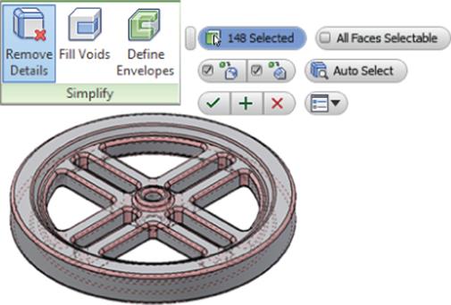
2. Fill Voids Often a part contains holes and pockets that are meaningful in the mechanical design but are not important in BIM layout. You can use this tool to select and fill these voids in order to reduce the number of edges and faces and therefore simplify the model's geometry.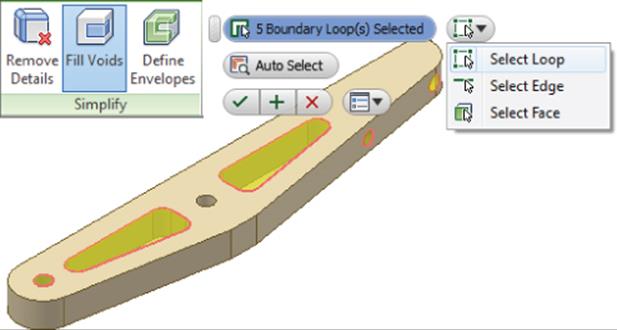
3. Define Envelopes Use this tool to reduce the number of faces and edges of complex features in order to make part models easier to work with. For instance, you might represent a highly intricate machined feature with a simple bounding box.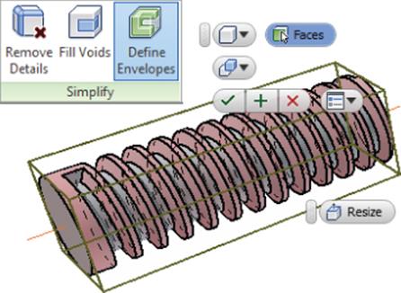
Recognize Revit Features
Many Inventor users create models to be used in Autodesk Revit libraries. To assist with this, it can helpful to set up the model so that it imports into Revit smoothly and predictably. You can make your models more “BIM ready” by using the Recognize Revit Features tools. Once features are recognized, you can enter the BIM Exchange environment to author the model for Revit export.
1. Recognize Extrude Recognizes Inventor extruded features and converts them to extrusions recognized by Revit
2. Recognize Revolve Recognizes Inventor revolved features and converts them to revolutions recognized by Revit
3. Recognize Sweep Recognizes Inventor swept features and converts them to sweeps recognized by Revit
4. Auto Recognize Automatically recognizes Inventor extruded and revolved features and removes fillets and chamfers
Model Authoring
The BIM Exchange environment allows you to author Autodesk Revit family data in your Inventor model and create connector objects such as cables, conduits, ducts, and pipes on the simplified model. These connector objects define the interfaces, which are the connection points between Inventor and the BIM model. Inventor allows you to create, edit, and delete connector objects. Here are the steps to create a conduit connector:
1. On the Get Started tab, click the Open button.
2. Browse for mi_13a_444.ipt in the Chapter 13 directory of your Mastering Inventor 2015 folder and click the Open button.
3. Select the Environments tab and click the BIM Exchange button.
4. From the MEP Author panel, click the Conduit Connector button.
5. In the Conduit Connector dialog box, select Circular as the shape for the connector (using Undefined allows you to select any oval, circular, or rectangular face).
6. Select the yellow circular face to place the connector. The location of the connector appears as a cylindrical arrow. Click the direction button to reverse the connector direction so that it points out away from the box.
7. Click the check box in the Size field and enter a value. Or you can leave the check box deselected to have the value linked to the model.
8. In the Connection Type drop-down menu, select Threaded.
9. Click the OK button to create the connector. Figure 13.8 shows the Conduit Connector dialog box.
10.Use the Pipe Connector button on the MEP Author panel to add a supply pipe connection to the blue circular face. Take a moment to explore the System Type options and author this connection with a type and property values of your choice.
11.Use the Duct Connector button on the MEP Author panel to add an exhaust duct connector to the rectangular face on the top of the unit. Again, set the properties to values of your choice and explore the options available.
12.Expand the MEP System Connections folder in the browser, as shown in Figure 13.9, and you'll find all of your connections categorized in subfolders. You can edit, delete, and suppress connectors as needed.
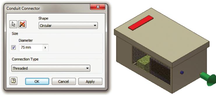
Figure 13.8 Adding a conduit connection
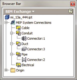
Figure 13.9 MEP system connections in the browser
Feel free to create new connections to explore these tools further. When finished, you can close the file without saving changes.
Model Publishing
A part in the BIM Exchange is the basic unit, that is, a specific size of the component placed within a part family. The part has instance-specific properties associated with it, such as a name and geometric representation. You can use the Export Building Components tool to save model geometry, properties, and connectors to an Autodesk exchange file (*.adsk) or a Revit family file (*.rfa). An ADSK file can be read by programs such as Revit MEP and AutoCAD MEP. However, Revit family files are typically preferred by Revit users because they provide a more direct handoff of the library data.
When publishing a model, it's often useful to set up the user coordinate system (USC) to match the destination coordinate orientation so that the models do not import upside down or flipped over. You can do this in the BIM Exchange environment by creating a UCS and then specifying its use when exporting the data.

In the following exercise, you will set up a model to be exported from Inventor and imported into Autodesk software. Follow these steps to publish a model in the BIM Exchange tools:
1. On the Get Started tab, click the Open button.
2. Browse for mi_13a_445.ipt located in the Chapter 13 directory of your Mastering Inventor 2015 folder and then click the Open button.
3. Choose the Environments tab and then click the BIM Exchange button. Note that the connectors have been authored already. Do not be too concerned that this exercise model is not realistic in its configuration; its purpose is merely to demonstrate the available tools.
4. Click the UCS button in the BIM Exchange tab to define a new user coordinate system.
5. Specify the origin by choosing the vertex at the bottom corner indicated with the black arrow, as shown in Figure 13.10.
6. Specify the x-axis by choosing the corner near the black X, and specify the y-axis by choosing the corner near the black Y.
7. Notice the new UCS node in the browser. You can rename it by clicking it twice slowly.
8. Click the Check Design button and notice the listing of information. The green check marks indicate that the information required is present. Yellow check marks warn you if some information is missing. Click the OK button.
9. Click the Check Revit Features button and wait for the *.html report to open in your web browser.
In the Feature Check Report you'll see that there is an error with the feature called Base2. To resolve this, you could exit the BIM Exchange environment and use the BIM Feature Recognize tool to convert Base2 into extrude features that Revit will recognize. For now, though, you can ignore the error, close the report, and continue.
10.On the BIM Exchange tab, click the Export Building Components button.
11.To set the component type, click the Browse button.
12.Choose the following selections from the drop-down menu using the plus buttons to expand the selections:
· 23.75.00.00 Climate Control (HVAC)
· 23.75.70.00 HVAC Distribution Devices
· 23.75.70.17 Water Heated And Cooled
· 23.75.70.17.34 Unit Heaters
13.Click the OK button.
14.Enter the following information in the Component Properties area. All iProperty fields pulled from the model have a cyan background. When the Model Property option is selected, model properties are exported with the component. You can clear this if you do not want to include this information.
Description Enter Climate Control Unit Heater.
Manufacturer Enter MI, Inc.
Model Enter 12345–6T.
15.Choose a user UCS from the Orientation drop-down.
16.Change the File Type drop-down at the top of the dialog box so that it is set to Autodesk Exchange Files (*.adsk).
17.Set the Thumbnail option to Import From File and then click the Import button to browse for the file called Unit Heater 1200 Series.png, found in the Chapter 13 folder.
18.When the thumbnail is set, click the Apply Changes button.
19.Click the OK button in the Export Building Components dialog box to save an ADSK file (you can click Cancel and choose not to save this file if you'd like).
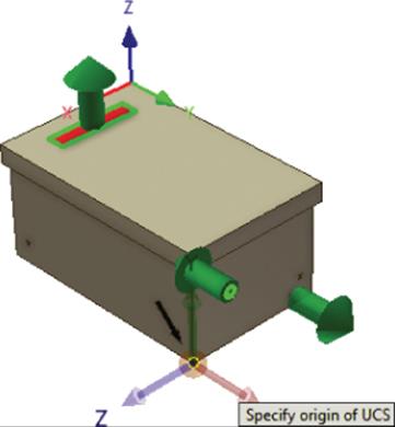
Figure 13.10 Creating a new user coordinate system

A Typical Scenario for the BIM Exchange
Say your company uses Inventor and specializes in electrical and mechanical designs and that you supply the air conditioner for a building being designed by an architectural firm. To minimize the risk of losing information and future rework, you meet with the architectural and construction firms to ensure that the interfaces between your product and the building are all agreed on. The architects and contractors do not care about any internal details of the air conditioner unit and actually prefer having a lightweight model that will not add extra overhead to the Revit model, but they are extremely sensitive to any changes in the interfaces between your product and their work.
The plan is to author your model and interfaces in Inventor and send the design to the architectural firm so that they can use your model to know exactly the dimensions and locations to tie into. Although you can output the files from the BIM Exchange tools to Revit users as is, it becomes apparent that having your products authored in Revit format will allow Revit designers to specify your products in their designs more quickly and accurately.
Depending on the relationship you have with the architectural firm, you may be able to trade the simplified models that you output from the BIM Exchange tools in return for the fully functional and tested Revit family files to be placed on your company's website for download by other firms that would like to specify your product line in their designs. If the architectural firm does not have the time to do this for you, it may be determined that hiring outside help to test and verify Revit files is the way to go.
Using AutoLimits
The AutoLimits tool allows you to monitor model changes so that you can reduce errors and engineering changes. You can think of it as a sensor. For example, say you are a plastics manufacturer and want to analyze the situation when the wall thickness of the components becomes too thin, or perhaps you are a machinist and want to know when two holes come too close to one another. You want to define this “check” and ensure that such a situation is caught early in the design. With AutoLimits, you can set up these limits and let the system warn you.
The AutoLimits that you create with the tool are passive and do not drive geometry or stop a feature from violating a limit. They simply notify you when it does. Another way to look at the AutoLimits tool is as a persistent Measure tool. With the standard Measure tool, the result of a measurement is not saved, whereas with the AutoLimits tool the measurement persists. When you open a file, the AutoLimits you have created are not shown unless you activate the AutoLimits panel bar.
The AutoLimits tool monitors the following limits:
1. Dimensional Length, Distance, Angle, Diameter, Minimum Distance
2. Area-Perimeter Area, Perimeter
3. Physical Property Volume, Mass
Figure 13.11 shows the AutoLimits tool icons as accessed from the AutoLimits panel of the Inspect tab.
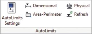
Figure 13.11 AutoLimits access
Turn On AutoLimits
If you do not see the AutoLimits tools on the Inspect tab, navigate to the Tools tab and click the Add-Ins button. Click AutoLimits in the Add-Ins list and then select the Loaded/Unloaded check box at the bottom of the dialog to load the AutoLimits tools. You can select the Load Automatically check box to have Inventor load them for you on startup.
Feedback is given to the user in terms of shape and color, as in the following examples:
· A green circle means it is within the boundary limit.
· A yellow inverted triangle means it is near the boundary limit.
· A red square means it is beyond the limit.
Figure 13.12 shows the different types of AutoLimits and their settings. (Click the AutoLimits Settings button shown in Figure 13.11 to access this dialog box.) You can control the visibility of each AutoLimits type by using the On and Off radio buttons. In an assembly, only the edited document's AutoLimits are visible in the browser; in other words, AutoLimits at subassembly levels are not visible or available unless that subassembly is edited.
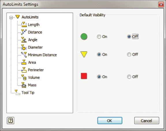
Figure 13.12 The AutoLimits Settings dialog box
To see AutoLimits in action, follow these steps:
1. On the Get Started tab, click the Open button.
2. Browse for mi_13a_002.ipt located in the Chapter 13 directory of your Mastering Inventor 2015 folder and click the Open button.Browse for mi_13a_002.ipt located in the Chapter 13 directory of your Mastering Inventor 2015 folder and click the Open button.
3. On the Inspect tab, click the AutoLimits Settings button, ensure that all three Default Visibility options are enabled, and then click the OK button. This part has a layout sketch on which the solid was based. The length has been left undefined by creating the visible driven dimension. Two AutoLimits have been added. The first alerts you if the distance from the front edge to the rectangular cut becomes too thin, and the second alerts you if the mass of the part becomes too heavy. To adjust the model, follow these steps:
A. Click the sketched point or construction line and drag in or out.
B. Use the Update button (select it from the Quick Access bar) to see the edit take place.
4. Drag the sketch point out so that the visible dimension is around 470 and click the Update button. Note the red square in the middle of the part. This is the Mass AutoLimit, indicating that the current length causes the part to be too heavy.
5. Drag the sketch point in so that the visible dimension is less than 300 and click the Update button. Note the red square on the edge of the part; this is a lower limit, Length AutoLimit, indicating that the current overall length causes the width between the rectangular cut and the edge of the part to become too thin.
To see these AutoLimits in the browser, you can click the white arrow on the browser bar and change from the Model browser to the AutoLimits browser (you might need to use the Refresh button on the AutoLimits panel first). Once you've explored these existing AutoLimits, you can close this file without saving the changes and continue to create AutoLimits.
Loading AutoLimit Tools
When you load a file that contains existing AutoLimits, the AutoLimits tools are not loaded or displayed in that file until you use an AutoLimits tool. A quick way of doing this is to use the Refresh button on the AutoLimits panel.
Creating AutoLimits
AutoLimits come in three types: Dimensional, Area-Perimeter, and Physical Properties. In the following steps, you'll create a Minimum Distance limit and then define the limit boundaries:
1. On the Get Started tab, click the Open button.
2. Browse for mi_13a_003.ipt located in the Chapter 13 directory of your Mastering Inventor 2015 folder and click the Open button.
3. On the Inspect tab, click the AutoLimits Settings button.
4. Set all three default settings to On and click the OK button.
5. Click the Dimensional button in the AutoLimits panel.
6. On the left of the dialog box, click the Minimum Distance AutoLimits button (the last one on the bottom).
7. For the selections, you can click the edges with work axes running through them, or you can click the axes (the axes are not required and have been placed just to help identify the correct edges).
8. Click the Boundary tab.
9. Click the Click To Add bar to place the green target AutoLimit.
10.Set the Lower value to 50 mm.
11.Rather than setting an Upper value, you will change the USign column so that the Upper limit is open-ended. Click the < under USign and choose the blank or empty entry from the drop-down.
12.You want to add another row to define the lower limits. To do so, hold down the Ctrl key and click the Click To Add bar. The new row should appear above the previous row in the table.
Setting AutoLimits Boundaries
Hold down Alt and click the Click To Add bar before you add any boundaries. This will place all five boundary levels at once, allowing you to define the green “target” boundary as well as a yellow “warning” and a red “danger” boundary on each side of the target.
Clicking the Click To Add bar always adds an upper boundary unless the green target boundary has been set to have no upper value. Clicking the Click To Add bar while holding down the Ctrl key always adds a lower boundary unless the green target boundary has been set to have no lower value.
You can add as many ranges as required when using the standard Click To Add or Ctrl+click methods; however, you can have only one range (five boundaries) when using the Alt+click method.
13.Click the yellow triangle twice slowly in the Level column and change it to the red square in the drop-down.
14.Set the Upper value to 49.999 mm.
15.Change the LSign column so that the lower limit is open-ended. Click the < under LSign and choose the blank or empty entry from the drop-down. Your boundary definition should resemble Figure 13.13.
16.Click the OK button and then click the OK button in the message dialog box.
17.You should see a green dot appear on your model; this is your AutoLimit.
18.Double-click the Length dimension and change the value to 299 mm.
19.Click the Update button (select it from the Quick Access bar) to see the edit take place. Note that the AutoLimit displays the red square, indicating that the distance is now below the value set as acceptable.
20.Change Length Dimension to 300 mm and click Update. Note that the AutoLimit displays a gray X. This indicates that there is a gap in the AutoLimit.
21.Hover your mouse pointer over the gray X until it changes color; then right-click and choose Edit AutoLimits.
22.Click the Boundary tab.
23.Select the Lower limit for the green row, change 50 mm to 49.9999 mm, and then click any other cell. Note that it sets the value back to 50.000 mm.
24.Click the OK button to return to the model and note that the AutoLimit is now green, as shown in Figure 13.14.
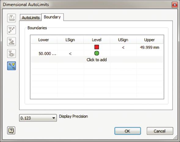
Figure 13.13 The Dimensional AutoLimits dialog box
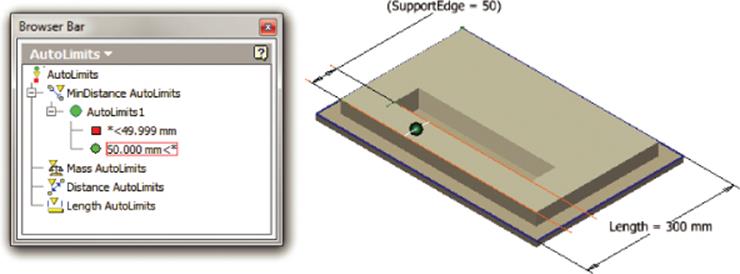
Figure 13.14 Length AutoLimits
AutoLimits are quite simple to set up and use. You can continue experimenting with this file and create other types of AutoLimits. Then you can close the file and continue.
Editing AutoLimits
You can view all the existing AutoLimits in your model by clicking the white arrow on the browser bar and changing from the Model browser to the AutoLimits browser. You can edit AutoLimits in the AutoLimits browser by selecting an AutoLimits entry and right-clicking it. I recommend you set the selection filter to Feature Priority because doing so makes it easier to select the AutoLimits glyphs. You can copy or delete AutoLimits by right-clicking them in the browser and choosing the appropriate command.
You can also create a group of AutoLimits to control the visibility of related AutoLimits. To do so, follow these steps:
1. Right-click the top node in the AutoLimits browser and select Create Group.
2. Right-click any AutoLimit and choose Copy AutoLimit.
3. Right-click the group and choose Paste AutoLimit.
4. Right-click the group to toggle visibility.
Don't Go Crazy with AutoLimits
In an assembly, use only the minimum number of AutoLimits required to monitor just the critical design information of interest. Using more than 10 AutoLimits can begin to impact the processing speed of your model. You can use AutoLimits in all environments except the Inventor Studio environment, the BIM Exchange, Dynamic Simulation, the construction environment, Solid Edit, the Flat pattern environment, and Engineer's Notebook.
Using the Design Assistant
The Design Assistant helps you find, manage, and maintain Inventor files and related documents, spreadsheets, and text files. Imagine your company is evaluating a new design that involves making minor changes to an existing design. You would like to reuse the parts, assemblies, drawings, and presentations as much as possible. Once you make the required changes and finish the new design work, you need to send the existing and modified designs to another department for their input on the overall design. The Design Assistant and Pack And Go tools can help in this scenario. You can perform searches, create file reports, and work with links across Inventor files. In addition, you can preview and view the iProperties.
You can launch the Design Assistant in any of three ways:
· Within Inventor, while a file is open, click the Inventor button and choose Manage ![]() Design Assistant.
Design Assistant.
· Right-click a file in Windows Explorer and select the Design Assistant tool.
· Select Start ![]() All Programs
All Programs ![]() Autodesk
Autodesk ![]() Autodesk Inventor 2015
Autodesk Inventor 2015 ![]() Design Assistant 2015.
Design Assistant 2015.
Managing Files in the Design Assistant
Note that the Manage button will not be visible if you open the Design Assistant from an actively open file in Inventor. To manage the links, you must open the file from the Design Assistant directly or via Windows Explorer, and they cannot be open in Inventor while you do this.
The Design Assistant dialog box, shown in Figure 13.15, contains three buttons in the left column: Properties, Preview, and Manage. You can open files using File ![]() Open. Figure 13.15 shows the result of selecting File
Open. Figure 13.15 shows the result of selecting File ![]() Open in an assembly named Demote_Stapler.iam. The assembly is listed in the left pane, and all parts related to the assembly are listed in the right pane.
Open in an assembly named Demote_Stapler.iam. The assembly is listed in the left pane, and all parts related to the assembly are listed in the right pane.
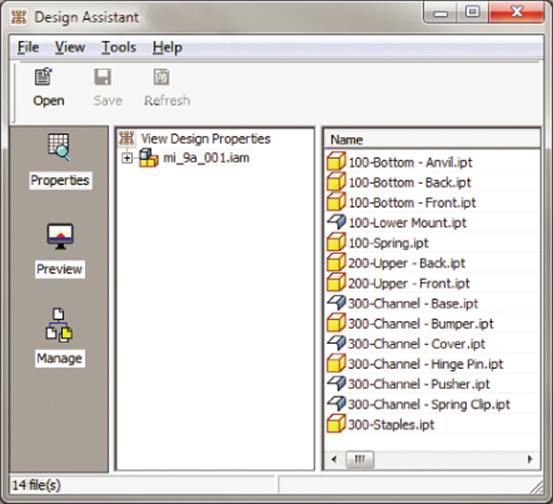
Figure 13.15 The Design Assistant dialog box
You can right-click any file in the Design Assistant and select View With Inventor View 1.0, which launches the Inventor View dialog box, shown in Figure 13.16. In this dialog box, you can use view functions such as Zoom, Pan, and Rotate.
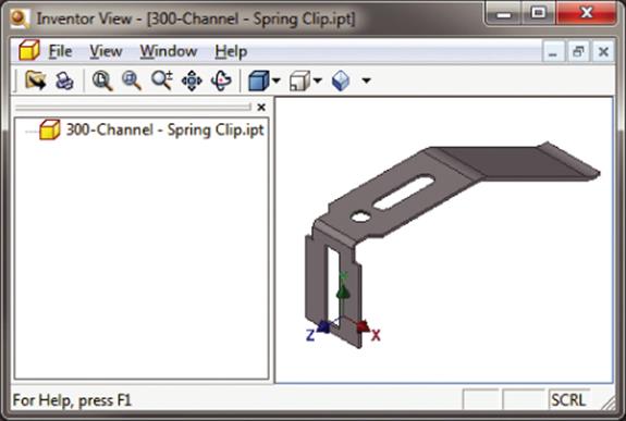
Figure 13.16 The Inventor View dialog box
Using the Inventor View Dialog Box
Autodesk Inventor View is a lightweight version of Inventor that can be used to view models and drawings. You can access it from the Design Assistant or from the Windows Start menu, or you can simply right-click a file in Windows Explorer and select View With Inventor View. This application is especially useful for nonengineering users who might need to view and print models and drawings but do not have the authority to edit or create models. The program can be downloaded from the Autodesk site and installed on a computer without installing Inventor.
To view the preview in the Design Assistant, you can click the Preview button in the Design Assistant dialog box, shown in Figure 13.17. The Design Assistant shows the preview for all the files. The figure shows the preview of the top-level assembly and one of the parts contained in the assembly. You can choose any listed file to display its preview.
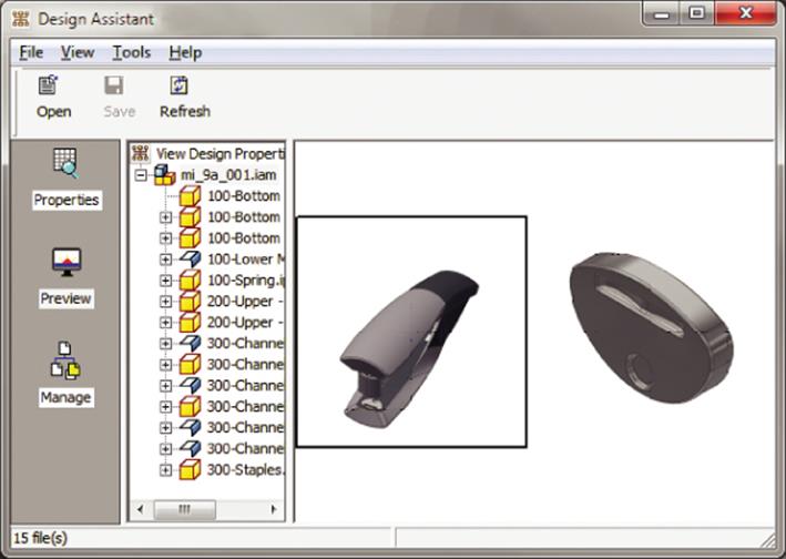
Figure 13.17 The Preview button in the Design Assistant dialog box
Using the Find Files Tool
You can use the Find Files tool to locate all references to a specified file. This can be useful when you are trying to determine how an edit, revision, or change order will affect existing designs. To use the Find Files tool, follow these steps:
1. Click the Manage button in the left column, as shown in Figure 13.18.
2. Click the Drawings, Assemblies, and Parts check boxes. These check boxes are located next to the text Include Files Of Type in the Design Assistant dialog box (only two are shown in Figure 13.18).
3. You can check Search Subfolders, shown next to the Parts check box in the Design Assistant dialog box, to include subfolders.
4. Find Files will find the files that use the selected file. In Figure 13.18, 300-Channel—Spring Clip.ipt has been selected, as is shown in the top pane (the .ipt file extension is not shown), and the referencing files found are listed in the bottom pane.
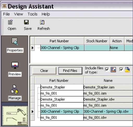
Figure 13.18 Using the Find Files function
Right-clicking a file and selecting iProperties gives you the properties for the selected part or assembly without opening the part or assembly in Inventor, as shown in Figure 13.19. Note that you do this after clicking the Properties or Preview button; the iProperty option is not available from the Manage view.
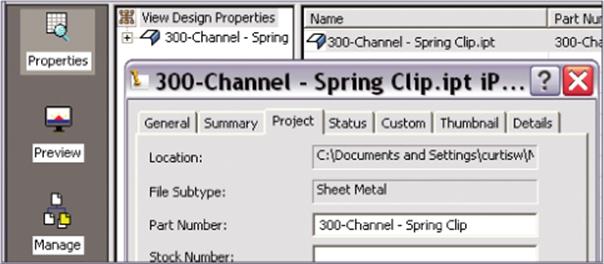
Figure 13.19 iProperties in the Design Assistant
Using the Where Used Tool
Selecting Tools ![]() Find
Find ![]() Where Used shows all the files that use the current file. For example, to find out which files use Assembly1.iam, you can do the following:
Where Used shows all the files that use the current file. For example, to find out which files use Assembly1.iam, you can do the following:
1. Select Tools ![]() Find
Find ![]() Where Used (in the Design Assistant dialog box). You will see the dialog box shown in Figure 13.20.
Where Used (in the Design Assistant dialog box). You will see the dialog box shown in Figure 13.20.
2. Select options in the Where Used dialog box, such as Parts, Drawings, Include Subfolders, and so on.
3. Click Search Now.
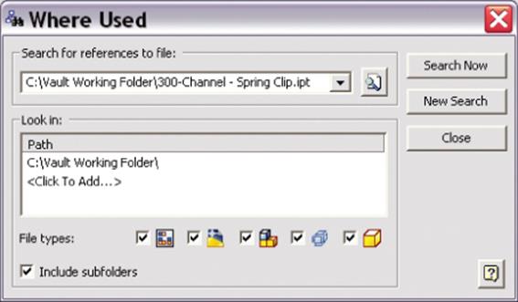
Figure 13.20 The Where Used dialog box
In the Path area under Look In, you can add paths that you want to search. The Where Used tool will list all the files where the specified file is used in some way. File relationships can include but are not limited to derived components and using a part file or assembly file in an assembly, drawing, presentation, and so on. Figure 13.21 shows a Where Used search that has been run using the Design Assistant on a file in the local Vault workspace. However, the Design Assistant is often used without Vault.
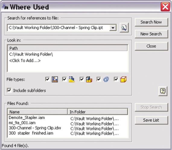
Figure 13.21 Results of clicking Search Now in the Where Used dialog box
Renaming, Copying, and Replacing Files
You can use the Design Assistant to perform management tasks such as renaming, copying, and replacing Inventor files without breaking the links to the files that reference them. This is because the Design Assistant not only performs the management task on the files but also “cracks” the referencing files and updates the link to the file at the same time. This is the fundamental difference between doing these operations in Windows Explorer (generally not recommended) and doing them in the Design Assistant.
Renaming Files with the Design Assistant
To rename a file that is in an assembly, drawing, or presentation, follow these steps:
1. Close Inventor.
2. Open the assembly, drawing, or presentation file in the Design Assistant.
3. Click the Manage button. In the Manage browser, click to select the component to be renamed. Right-click in the Action column and select Rename. All occurrences of the component are highlighted.
4. Right-click the Name column and select Change Name. In the Open dialog box, change the name and select Open (you're not really opening anything; you are just setting the name).
5. Click Save to apply the changes.
Copying Files with the Design Assistant
To copy a file that is in an assembly, drawing, or presentation, follow these steps:
1. Close Inventor.
2. Open the file in the Design Assistant.
3. Click the Manage button. In the Manage browser, click to select the component to be renamed. Right-click the Action column and select Copy. All occurrences of the component are highlighted.
4. Right-click the Name column and select Change Name. In the Open dialog box, enter the name of the new copy and select Open (you're not really opening anything; you are just setting the name).
5. Repeat steps 3 and 4 for all the files you want to copy. For instance, if you are copying a drawing and the part that this drawing details, you would complete steps 3 and 4 for both the drawing and the part.
6. Click Save to create the copies. Your copies will be created right next to the original files.
This technique can be incredibly useful when you want to create a copy of an existing detailed design so that you can make changes to the copy. Create the copy of the drawings and the components and then make the changes.
Replacing Files with the Design Assistant
If you want to replace a part or assembly file with an assembly, you can right-click the Action cell and then select Replace. Right-click the Name cell for the component and then click Change Name. In the dialog box, select the replacement file. After a file is replaced, renamed, or copied, other files that reference the original file need an update. The Update option will be useful, as shown here:
1. Open the assembly file in the Design Assistant.
2. Click Manage and select files that are being modified from the upper browser.
3. In the lower browser, select the file types you want to include in the update.
4. Click Find Files. The referencing files are displayed in the lower browser.
5. Click the Save button to apply the changes.
The Design Assistant cannot make changes in certain circumstances. For example, it can't make changes when the active project is set to Semi-isolated, when the design state of a file is set to Released, when read-only permissions are set, or when you're trying to change the workgroup copy of the file.
The Design Assistant vs. Autodesk Vault
The Design Assistant can make many of the changes discussed here, but if you find yourself copying designs, changing filenames, and relinking projects often, you owe it to yourself to investigate Autodesk Vault. Vault can do all of these operations and much, much more.
Using Pack And Go
You can use the Pack And Go tool to package an Inventor file, such as a top-level drawing or assembly, and collect all of its referenced Inventor files in a single location. This is a useful feature for archiving a design and all the files related to the design into a single ZIP file. For example, suppose you had the following assembly:
· Assembly1.iam
· Part1.ipt
· Part2.ipt
· Part3.ipt
The problem is that you are not sure what directories the part files are in. Pack And Go can find all the parts for Assembly1.iam and copy them into a new directory. You can then zip the files in that new directory to be archived or sent to other users. You can access the Pack And Go tool by right-clicking in Microsoft Windows Explorer or from a Design Assistant session started outside Inventor. Click the Properties or Preview tab and right-click the assembly to access the Pack And Go tool.
To use Pack And Go on an assembly, follow these steps:
1. Click the Inventor button and choose Save As ![]() Save As Pack And Go. This will open the Pack And Go dialog box.
Save As Pack And Go. This will open the Pack And Go dialog box.
2. Set the destination directory to the folder in which you want to copy the files.
3. If you have multiple project files, use the Browse button to ensure that you are looking at the proper one.
4. Click the More button to display more Pack And Go options, as shown in Figure 13.22 (once clicked, the More button toggles to the Less button).
5. Click Search Now to find the IPT and IAM files that are referenced by the assembly file. They will appear in the Files Found section at the bottom of the dialog box.
6. This finds all the files referenced by the assembly file, but what if you know that the assembly and part files have drawings detailing them? To search for referencing files, click the Search Now button in the Search For Referencing Files area.
7. If files are found, you can select which ones to add and then click the Add button. Note that there is no progress bar in this dialog box, so you have to watch the top of the dialog box and wait for “Found # file(s)” to appear to know that it is done, as shown in Figure 13.23.
8. Click the Start button to start the copying process. Once the files are copied, the Cancel button turns into a Done button to let you know.
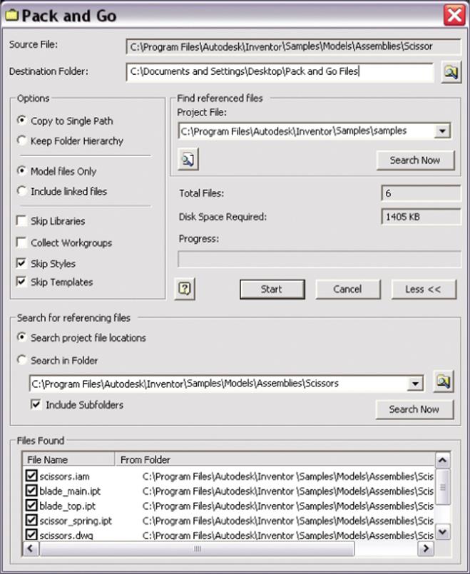
Figure 13.22 The Pack And Go dialog box
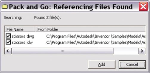
Figure 13.23 Pack And Go referencing files found
Typically you will want to configure some of the options because these will yield different Pack And Go results:
1. Copy To Single Path This copies the referenced files to a single folder, reducing folder hierarchies. If any files have the same filename, only one of the files can be placed at the destination folder.
2. Keep Folder Hierarchy This preserves the folder hierarchy under the destination folder. Use this option for round-trip file transfers such as sending files to a contract worker or customer or when you are packing files to work on a laptop while offsite. Maintaining the folder hierarchy will allow you to move the files back to the original destination smoothly when they return.
3. Model Files Only This copies only Inventor files (with filename extensions .iam, .ipt, .idw, .dwg, and .ipn) to the destination folder. Referenced files such as spreadsheets, embedded pictures, and text files are not copied.
4. Include Linked Files This includes referenced files such as spreadsheets, embedded pictures, and text files.
5. Skip Libraries When this is selected, all files found in a library path, such as Content Center files and user-defined library files, are excluded from the Pack And Go tool.
6. Collect Workgroups If this is selected, workgroups and the workspace are collected into a single folder. This is typically relevant only when working with a legacy project type.
7. Skip Styles If this is selected, style XML files are not copied with the packaged file.
8. Skip Templates Templates are not copied with the Pack And Go files when this option is selected. You can generally use this option and deselect it only for special circumstances.
It is important to note that Pack And Go does not modify the source files. When you package Inventor files, they are copied to the new destination. A log file and a copy of the original project file with a .txt suffix are also copied to the destination folder. Changes made to the packaged files do not affect source files.
Here are some common uses for Pack And Go:
· Archiving so that you can package files on a CD or DVD.
· Sending files to another user.
· Separating the referenced files from other files in the same source folders.
· Copying an assembly to a new location and then creating a design variant by making changes to the copy. The original is unaffected.
Using Pack And Go as a Cleanup Tool
Pack And Go can be useful as a project cleanup tool. Often a project folder will become cluttered with numerous unused files. Use Pack And Go on the top-level drawing or assembly and copy all the files to a secondary location. Then delete the contents of the original folder and replace them with the cleaned-up copies.
Pack And Go uses the active project file. You can change the active project file. If you have files in multiple locations, the project file must specify all those locations.
Using the Drawing Resource Transfer Wizard
The Drawing Resource Transfer Wizard helps copy drawing resources such as borders, title blocks, and sketched symbols from one source drawing to one or more destination drawings. To use the tool, you have to close Inventor just to avoid a situation where you are in the middle of modifying a drawing and you want to use that drawing as part of the process for transferring resources.
For example, imagine your company has hundreds of drawings in Inventor. However, there has been a change in the standard note that is on every drawing. If the standard note was created as a sketched symbol, this update can be batched. The transfer wizard is an ideal solution to solve this kind of problem.
Follow these steps to use the wizard:
1. Select Start ![]() All Programs
All Programs ![]() Autodesk
Autodesk ![]() Autodesk Inventor 2015
Autodesk Inventor 2015 ![]() Tools
Tools ![]() Drawing Resource Transfer Wizard.
Drawing Resource Transfer Wizard.
2. On the welcome screen, click Next.
3. On the Select Source Drawing And Resources screen, select the drawing template and then click the OK button.
4. This loads the preview (if available) under Preview and shows the available drawing resources hierarchy in the source under Source Resources. You can deselect the resources you don't want to transfer to the destination. Figure 13.24 shows the source drawing resources.
5. Click Next to go to the Select Target Drawings screen. On this page, select one or more drawings (by Shift+clicking) and click Open. You can click the file or path column name to sort files.
6. Click Next and select Yes or No for replacing resources in the target file with the same name as in the source. If you select Yes, the same name is used as the source for the target file. Selecting No gives a unique name to target drawing resources that have the same name as those in the source file. For instance, instead of writing over a title block definition named TB_100, you would end up with TB_100 and Copy Of TB_100 in your files.
7. Click Start, which shows the progress bar and a Pause button to temporarily halt the process.
8. When the progress bar finishes, click Exit to complete the process.
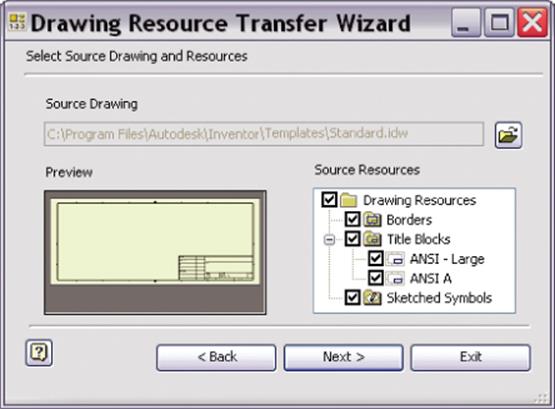
Figure 13.24 Selecting source drawing resources
If you have a number of old drawings that you need to bring up-to-date with a new standard, this tool is useful.
Using the Wizard for New Title Blocks
A problem that pops up quite often in manufacturing is changing title blocks. Companies change addresses, change logos, and get bought or merged; any number of things can happen to require you to have to change your title block. This is where the Drawing Resource Transfer Wizard can come in handy. Simply edit the title block as required in your template file and then transfer it to all your old drawings.
Using the Style Library Manager
A helpful style tool that is external to Inventor is the Style Library Manager. This tool can be used to manage style libraries in your template files and set up style libraries. You should consider using this tool when attempting to remove unwanted styles from templates. You can access it by selecting Start ![]() All Programs
All Programs ![]() Autodesk
Autodesk ![]() Autodesk Inventor 2015
Autodesk Inventor 2015 ![]() Tools
Tools ![]() Style Library Manager.
Style Library Manager.
You can use this tool to copy, rename, and delete style libraries. For example, imagine you are a CAD administrator who rolls out all the standards for your company, and you want to ensure that a good library of styles exists for others to use. The Style Library Manager comes to the rescue in this situation. You can create a new style library using the Create New Style Library button, shown in Figure 13.25 under the Style Library 2 column. Any changes in the style library are not available in other documents until Inventor closes and a new session is reopened.
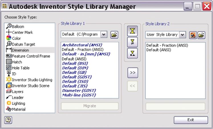
Figure 13.25 The Style Library Manager
You can reuse your styles by copying them from one style library to another. Follow these steps:
1. Click the Style Library Manager tool.
2. In Style Library 1, click the drop-down arrow to select the source library styles you want to copy or use the Browse button.
3. In Style Library 2, you have three options:
· Choose an existing library.
· Copy an existing style library.
· Create an empty style library.
Use the Create New Style Library button to select the last two options or use the Browse button to use the first. Figure 13.26 shows a new empty library being created.
4. Click one or more styles in Style Library 1 and then click the ![]() button to add them to Style Library 2. Click the arrow buttons to add styles to or remove styles from the destination as desired.
button to add them to Style Library 2. Click the arrow buttons to add styles to or remove styles from the destination as desired.
Creating a new empty library and then bringing in approved styles one at a time is the best way to ensure that you a get a clean style library with only the styles you want and nothing else.
5. In Style Library 1 or 2, you can right-click a style name and select Rename or Delete. A warning will appear that all document links to that style will be broken or the style will be permanently deleted from the style library. Click Yes to continue and enter a new name. Click No to cancel the Rename or Delete operation. Note that you cannot undo or reverse a deletion.
6. Changes are saved as you make them. Once all changes have been made, click the Exit button.
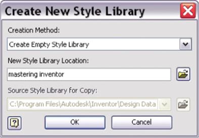
Figure 13.26 Creating a new style library
Using the Task Scheduler
A large design repository needs to have a way to manage tasks for efficiency and repeatability. Nonproductive and mundane tasks tend to be expensive and tedious. The purpose of the Task Scheduler is to precisely automate such tasks. To access the Task Scheduler, select Start ![]() All Programs
All Programs ![]() Autodesk
Autodesk ![]() Autodesk Inventor 2015
Autodesk Inventor 2015 ![]() Tools
Tools ![]() Task Scheduler.
Task Scheduler.
Imagine you are working for a service company that handles outsourcing work for auto suppliers. The supplier works with hundreds of files and is trying to decide whether to move to Inventor 2015. You have been asked to evaluate this for the supplier. You want to do testing and present quantitative data on the results of migration or some other custom tasks the supplier normally performs on legacy files. The main purpose of the Task Scheduler is to automate the tasks and quickly give you results. The Task Scheduler has the ability to create tasks such as the following:
· Migrating a set of files from Autodesk AutoCAD, Autodesk Mechanical Desktop, and Autodesk Inventor software
· Converting Inventor IDWs to Inventor DWGs
· Publishing DWF files
· Importing files and exporting files
· Updating parts, assemblies, and drawings
· Checking out and checking in from Vault
· Retrieving files from Vault
· Printing sheet sets
· Refreshing Content Center components used in assemblies
· Running a custom macro (such as a Visual Basic routine)
· Creating a single part from an assembly using the Shrinkwrap tool
Creating a Task for Migrating Files
To create a task to migrate files in Task Scheduler, follow these steps:
1. Open Task Scheduler by selecting Start ![]() All Programs
All Programs ![]() Autodesk
Autodesk ![]() Autodesk Inventor 2015
Autodesk Inventor 2015 ![]() Tools
Tools ![]() Task Scheduler.
Task Scheduler.
2. Select Create Task ![]() Migrate Files, as shown in Figure 13.27.
Migrate Files, as shown in Figure 13.27.
3. In the Migrate Files dialog box (see Figure 13.28), enter the task name, frequency, start time, and start date. If Immediately is checked, the task will start immediately after you click the OK button. The log file helps you to see the output of the task.
4. Use one of the three buttons along the top to add files in one of the following ways:
Add Files Select files from the active project to add to the task.
Add Folder Browse to a folder or folders to add to the task. Use the File Name drop-down to select which file type to process. Ensure that the Recursive check box is selected to include subfolders.
Add Project Select a project to include all files in that project's search paths.
5. Click the Options button to open the Migration Options dialog box, shown in Figure 13.29. The options are also listed here:
Total Rebuild This rebuilds all the parts and assemblies.
Skip Migrated Files This ignores files created in the current version or files already migrated.
Skip Files With Unresolved References This ignores files with broken links and references.
Include Assembly Graphics For Express Mode This setting allows you to save Express mode graphics in the assembly when migrating assembly files. With Express mode graphics included, your migrated assemblies can then be opened in Inventor's Express mode. Without these graphics, assembly files can be opened only in Full mode.
Set Defer Updates (Drawings Only) This toggles on the setting that allows drawings to be made static so that they do not update as the part or assembly they detail updates. This can be toggled off manually from the drawing later.
Make All Raster Drawing Views Precise This updates drawing views from the draft preview of the drawing view (Raster View) to a fully calculated (Precise) drawing view.
Update Local Materials and Appearances This updates the material and appearance styles found in the file to match the material and appearance library styles.
Purge Old Versions This deletes former versions after the migration task finishes, keeping file size to a minimum.
Compact Model History This purges file history used for fast feature editing. This is intended for working with large assemblies when you experience capacity limitations. Do not select this option when migrating files to a new release.
6. Click the OK button to run the task. When the task is done, you will see the status shown as completed.
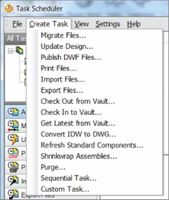
Figure 13.27 The Create Task menu
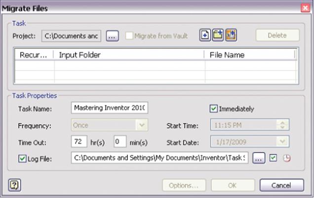
Figure 13.28 Migrating files
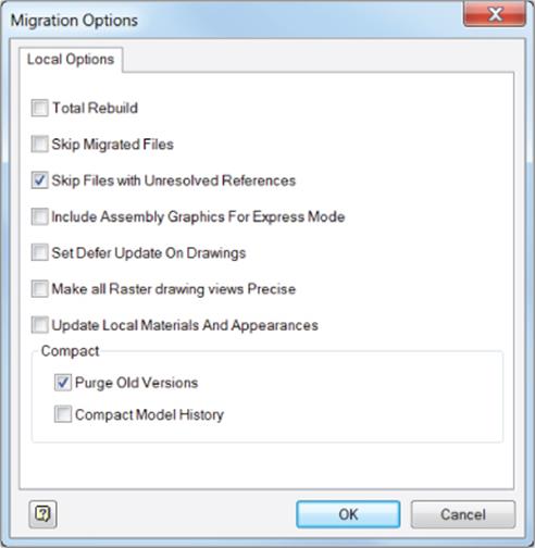
Figure 13.29 The Migration Options dialog box
Users can run, edit, delete, or disable tasks once they are created, as shown in Figure 13.30. Tasks are also saved so they can be run again. You can click the Task ID or Name column to sort the data by task ID or name.
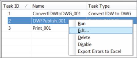
Figure 13.30 Editing a task
Performing Sequential Tasks
You can create several subtasks to set up multiple tasks and schedule them to run in a specified sequence at a specified time. Custom subtasks can be used also in a sequential task. One subtask can depend on the output of the previous subtask. Here are some examples of multiple subtasks:
· Importing files
· Updating designs
· Publishing DWF files
· Printing files
· Generating a cost report (custom task)
Performing Custom Tasks
A form of a COM object that implements the COM interface could be a custom task. For instance, you can use a custom task to open a batch of text files. A type library file called ServiceModuleInterfaceDef.tlb is shipped with the Task Scheduler. To access the COM interface, reference this file within your project. You can create custom tasks in any programming language that supports COM.
Tweaking Multi-Process Settings
In the Multi-Process Settings dialog box, shown in Figure 13.31, you can tweak parameters to complete batch jobs in less time by leveraging the multiprocess support in the Inventor Task Scheduler. Up to 16 processes can be run at the same time. You can set the number of processes and the amount of memory to be used. You can find this setting in Task Scheduler by selecting Settings ![]() Multiple Process.
Multiple Process.
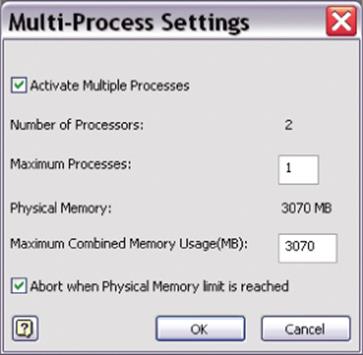
Figure 13.31 The Multi-Process Settings dialog box
Batch Plotting with the Task Scheduler
One of the most powerful uses of the Task Scheduler is to batch-plot a number of drawings. Simply select Print Files from the Create Task menu and then select the files to be printed. Click Options to set the paper size and other print parameters.
Publishing DWF Files and Filenames
If you were to use the Task Scheduler to publish a DWF file named MI777.ipt, then that would become the destination file MI777.ipt.dwf. Some users find this filenaming scheme difficult to accept. The motivation to rename it not as filename.dwf is as follows: If Inventor were to produce MI777.dwf from MI777.ipt, it might be overwritten if you have two files with the same name but different file extensions, that is, MI777.ipt and MI777.idw. Therefore, the Task Scheduler takes the current filename with the extension (such as .iptor .idw) and appends .dwf at the end. There are programs available on the Internet or Windows scripting commands to rename files from MI777.ipt.dwf to MI777.ipt to fix the filenames.
Using iProperties
Inventor files have file-specific properties known as iProperties. The iProperties dialog box helps you specify and view them. You can enter custom data into iProperties, search by those fields, and update your title blocks and parts lists in drawings and BOMs. You can launch this dialog box by clicking the Inventor button and then iProperties or by right-clicking the filename in the browser and selecting iProperties. Figure 13.32 shows the iProperties dialog box for a part. The iProperties dialog box in the parts and assemblies environments contains seven tabs, whereas the iProperties dialog box in the drawing environment contains only six tabs (the latter is missing the Physical properties tab).
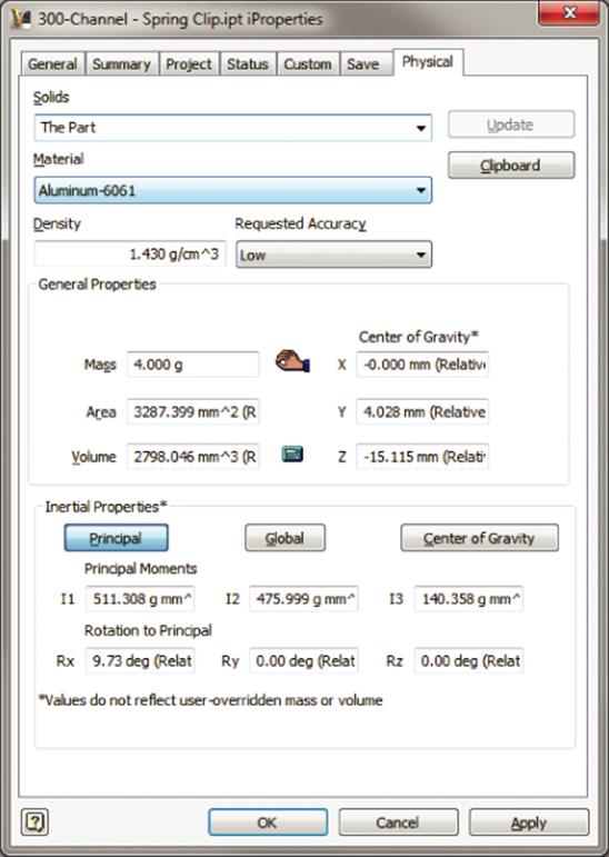
Figure 13.32 Physical properties with aluminum as the material
You can also right-click a file in Windows Explorer and choose Properties ![]() iProperties to add or edit iProperties outside of Inventor. Or from Windows Explorer, right-click a file and choose Design Assistant to work with files outside of Inventor. In the iProperties dialog box, you can modify data on the Summary, Project, Status, and Custom tabs. On unsaved files, changing the iProperties using the Design Assistant could lose unsaved changes. You can save any open Inventor files before using the Design Assistant to change iProperties.
iProperties to add or edit iProperties outside of Inventor. Or from Windows Explorer, right-click a file and choose Design Assistant to work with files outside of Inventor. In the iProperties dialog box, you can modify data on the Summary, Project, Status, and Custom tabs. On unsaved files, changing the iProperties using the Design Assistant could lose unsaved changes. You can save any open Inventor files before using the Design Assistant to change iProperties.
The various tabs in the iProperties dialog box are as follows:
1. General Contains fields that cannot be modified by the user.
2. Summary Contains fields that can be modified by the user, such as Title, Subject, and Author.
3. Project Contains important fields such as Part Number, Revision Number, and Project.
4. Status Contains drop-down controls for Part Number, Status, Checked Date, and so on.
5. Custom Helps define your attributes. These attributes follow the Name, Type, and Value format. For example, you can have Name=Department, Type=Text, and Value=Design123.
6. Save Helps you specify whether to save the preview picture of the file so that it can be used in most “browse for file” dialog boxes. You can also specify an image file to use for this preview picture.
7. Physical Lets you calculate and display the physical properties (area, volume, inertia, and so on) for a part or an assembly. The material selected is used to calculate the mass properties. The Update button on the Physical tab is useful to update the physical properties based on changes to your models.
The Summary, Project, Status, and Custom tabs are used to search files to update the BOM and parts lists.
Figure 13.32 shows an example of iProperties on a simple part. If this were a multi-body part, the mass properties of an individual property could be evaluated by setting the Solid drop-down to look at just the specified solid.
Also notice the hand icon next to the Mass input box. This indicates that the mass has been overridden or manually entered rather than being calculated from the part. The calculator icon shown next to the Volume input box indicates that the volume is being calculated from the part and will update as changes are made. The Density field cannot be changed in this dialog box. To change the density for this example, select the Manage tab, click Styles Editor, and find Aluminum-6061 under Material. Then change the density.
Overriding Mass and Volume for a Simplified Representation
Sometimes you'll want to model a simplified representation of a part but still need to have an accurate measure of its mass or volume. In these cases, type over the mass or volume in the iProperties dialog box. The calculator icon will then change to the hand icon, signifying that the mass and/or volume has been overridden. To allow Inventor to recalculate the mass or volume, delete all the text from the box and click the Update button. Inventor will then compute the mass and volume based on the size and density of the model.
Copying iProperties to Drawings
You can copy the model iProperties to the drawing iProperties so that they are the same. Copied model iProperties can be used in part lists, title block standard notes, or any annotation that accesses the iProperties. If the iProperties are set up in your drawing template, when you place views of the model on a new drawing, the selected iProperties are copied to the drawing from the source file.
Be aware that, once copied, the properties do not update automatically when changed in the model. To update the copied model iProperties in the drawing, select the Manage tab (from the drawing file) and click Update Copied Model iProperties. Note also that a drawing will pull properties from only one source. So if you have views of two different models on a single drawing, the properties are pulled from the first model from which a view was created. If you remove all the views of the first model, the drawing will pull from the second model, but you will need to use the Update button to make this happen.
You can copy iProperties from a model file to a drawing file by following these steps:
1. In the Drawing file, select the Tools tab and click Document Settings; then select the Drawing tab.
2. Click the Copy Model iProperty Settings button, which opens the dialog box shown in Figure 13.33.
3. Select the boxes for the properties you want to copy. You can select the All Properties check box at the bottom to copy all the properties.
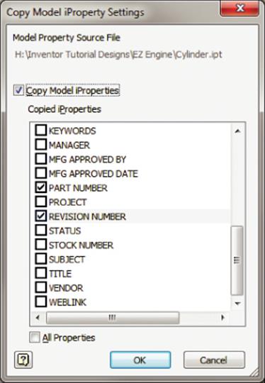
Figure 13.33 The Copy Model iProperty Settings dialog box
Creating Expressions with iProperties
If you have a need to create a “stock size” of your parts to be used in your BOM with associativity to model parameters, you can create and manage expressions for iProperties by using the following steps:
1. Click the Inventor button and then iProperties, and select the Summary, Project, Status, or Custom tab. Then click a field where an expression needs to be created.
2. Start with the = sign and type the text. If you want to include parameters or iProperty names, simply include them in brackets. A detected expression is denoted by fx. Figure 13.34 shows an expression that concatenates the thickness, width, and length parameters. This is the expression used:
![]()
The resulting Stock Number property is as follows:
![]()
3. To edit an existing expression, you can right-click the expression and choose Edit Expression.
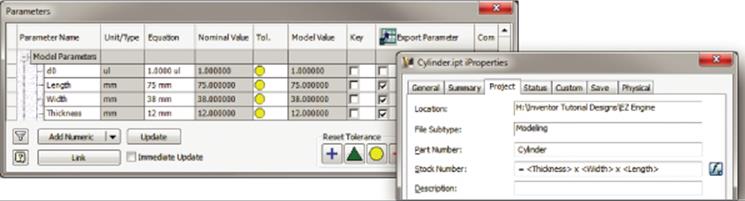
Figure 13.34 Concatenating text and parameters in iProperties
Before creating the expression from parameters, you should visit the Parameters dialog box (select the Manage tab and click the Parameters button) and do the following:
· In the Export Parameter column, click the check box next to all parameters you want to use in expressions. If you forget this step, the expressions will not build.
· In the Equation column, right-click the parameter and choose Custom Property Format. The Export parameter must be selected to get this option. Figure 13.35 shows the Custom Property Format options. Notice that you can click the option to apply the formatting to all comparable parameters. In other words, if it's a length parameter, set this format for all length parameters; if it's a volume parameter, set this format for all volume parameters; and so on.
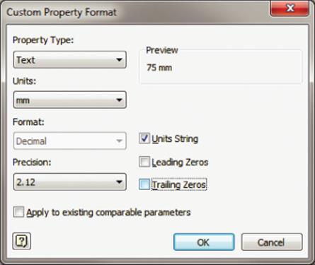
Figure 13.35 Customizing an exported parameter format
To promote reuse, create a template file with predefined expressions for iProperties that lets you unify your parts list and other documentation. The Bill Of Materials dialog box provides the Property Expression Builder, which helps you create expressions for iProperties as well. You can then copy the expression to the parameter field of multiple parts in the Bill Of Materials Editor. Using the Bill Of Materials Editor allows you to “reach into” several parts at once and set an expression en masse. Figure 13.36 shows an iProperty expression being created in the Bill Of Materials Editor.
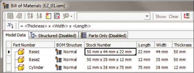
Figure 13.36 Expression Builder in the Bill Of Materials Editor
Working with the Design Assistant and iProperties
You can use the Design Assistant to copy design properties from one Inventor file to another. To do so, use the following procedure:
1. In Inventor, click the Inventor button and choose Manage ![]() Design Assistant.
Design Assistant.
2. In the Design Assistant, select Tools ![]() Copy Design Properties to access the Copy Design Properties dialog box.
Copy Design Properties to access the Copy Design Properties dialog box.
3. Set the source file in the Copy From box.
4. Select the properties to copy.
5. Select the destination files to receive the properties.
6. Click the Copy button.
7. If the properties exist in the destination file, you are prompted to overwrite them one by one; you can choose Yes To All or No To All as well.
8. Once the properties are copied, click Done.
9. You can then step into the files (from Inventor or the Design Assistant) and change the values of the copied iProperties as required.
Figure 13.37 shows the custom iProperties of one file being copied to another file. You can refer to the section “Using the Design Assistant” earlier in the chapter to learn more about the Design Assistant and iProperties. If the active project is set to Shared or Semi-isolated, you cannot copy properties to a file that is checked out to someone else or into the workgroup version of a file.
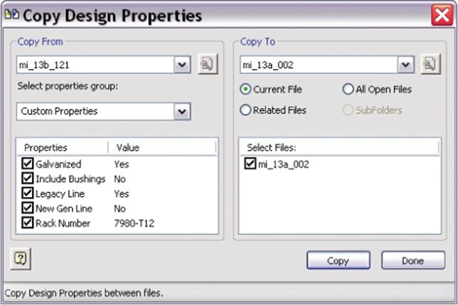
Figure 13.37 Copying custom iProperties from one file to another
Creating Design Property Reports
You can use the Design Assistant to create a design property report that shows the iProperties you've selected. The report is written out to a TXT file. In the properties view browser in the Design Assistant, you can select the design properties to display for files:
1. While in the properties view, select View ![]() Customize in the Design Assistant and select the required property group.
Customize in the Design Assistant and select the required property group.
2. Select the properties to display. Clicking the Add or Remove button helps you move a property from the Available Properties list to the Selected Properties list. You could also double-click it. The Name property is a default property that is mandatory in all displays.
3. To include custom properties that you've created yourself, follow these steps:
A. Set the Property Group drop-down to Custom Properties.
B. Click the New button.
C. Expand the Add New Property column using the ![]() button.
button.
D. Use Ctrl or Shift to select multiple properties.
E. Click Apply. Note that only nine properties may be listed.
4. Click Done. Notice that the properties you selected are now listed as columns.
5. Select Tools ![]() Reports and choose the report type you want:
Reports and choose the report type you want:
Hierarchy Report Shows the hierarchy within the selected folder or assembly. If a folder is selected, the report shows the subfolders it contains. If an assembly file is selected, the report shows the paths for the files in the assembly.
Design Property Report Shows values of the specified properties for the files in the selected file or group of files.
6. Choose the number of levels to display and click Next.
7. Specify the report name and save location.
Using the Measure Tools
The Measure tools let you measure distances, angles, loops, and areas. These tools, shown in Figure 13.38, are available by selecting the Inspect tab and then looking on the Measure panel. They are available in the assemblies, parts, sheet-metal, flat pattern, construction, and 2D and 3D sketch environments. You can select sketches, edges, faces, bodies, and work geometry to take measurements. In addition to the measurement tools mentioned, you can use Measure Regions while in a 2D sketch.
1. Distance Lets you measure the length of a line, an arc, or the distance between points and so on.
2. Angle Lets you measure the angle between points, edges, or two lines. To measure between points, click two points to define a line and then a third point to measure the angle.
3. Loop Gives you the length of the loops. For 2D sketches, it measures open or closed loops. For 3D sketches, it measures only open loops.
4. Area Gives you the area of closed regions.
5. Region Properties Calculates the area, perimeter, and the area moment of inertia properties of 2D sketch loops. Measurements are taken from the sketch coordinate system.
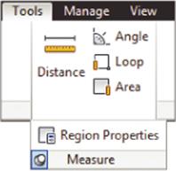
Figure 13.38 Measure tools
Using Measurement Helpers
Measurements can be accumulated, cleared, and displayed in different ways. Figure 13.39 shows some of the options that are useful while using the Measure tools.
1. Add To Accumulate Adds the current measurement to the total sum
2. Clear Accumulate Resets the sum to zero
3. Display Accumulate Displays the current sum
4. Dual Unit Lets you see the measurement in the desired units
5. Precision Displays eight formatting values and the option to display all decimals
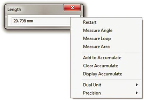
Figure 13.39 Measurement helpers
One of the advantages of using the Measure tools is the ability to enter feature parameters by measuring instead of by directly entering them. For example, in Figure 13.40, extrusion depth can be entered as a known value. Alternatively, you can select the Measure tool from the Depth flyout and then select a model edge. The length of the edge will appear in the Depth control of the Extrude dialog box. This is a convenient way to input dimensions by measuring instead of directly entering the values into the dialog box. In the graphics window, click the geometry to measure. The measurement is transferred to the dialog box automatically. Note that this tool can be used with sketch dimensions as well.
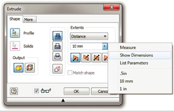
Figure 13.40 Measure tool and feature parameters
Also shown in Figure 13.40 is the Show Dimensions option. Choosing this option allows you to select an existing feature to temporarily see the consumed dimensions within that feature. You can then select a dimension on-screen to link the value of that dimension to the dimension you are currently entering. This differs from the Measure method in that the value will update if the object changes, whereas the measured value will stay static.
Measuring in Assemblies
Since you have faces and components in assemblies, there is a need to differentiate measuring between them. In the context menu, you can change the selection priority.
When Component Priority is selected, the minimum distance is measured between subassemblies. Part priority signifies measurement between parts only. Faces And Edges Select Priority lets you select only faces and edges, which is the default when nothing is preselected. Changing the selection priority resets any existing selections. Figure 13.41 shows the priority type pull-down with the selection filters for Component, Part, and Faces/Edges.
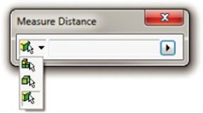
Figure 13.41 Selection priority for measurements
You can measure preselected entities by selecting the object first and then clicking the Measure button. If a selection set is valid for a measurement, the select filter in the Measure dialog box is updated, and the measurement is displayed. For example, if you select two points and then start the Measure Distance tool, you will get the distance between the points. However, if you select three points and start the Measure Angle tool, the selection set is cleared because the tool doesn't know which point is the vertex of the angle.
Participating in the CIP and CER
The Customer Involvement Program (CIP) aids in collecting information about your use of the Inventor software. Customer error reporting (CER) aids in sending information to Autodesk when the software program closes unexpectedly.
Participating in the CIP
To guide the direction of the Autodesk design software in the future, your use of the Inventor software is forwarded to Autodesk if you participate in the CIP. You can access this feature by selecting Help ![]() Customer Involvement Program. In the Customer Involvement Program dialog box, you can select a level of participation and then click the OK button. The following information might be collected:
Customer Involvement Program. In the Customer Involvement Program dialog box, you can select a level of participation and then click the OK button. The following information might be collected:
· Autodesk product version and name
· Inventor commands and time spent
· Error conditions (catastrophic and nonfatal)
· Information such as system configuration, IP address, and so on
The CIP is committed to privacy protection. It can collect neither drawing or design data nor personal information such as names, addresses, and phone numbers. It will not contact users by email or any other way. The Customer Involvement Program aids in letting Autodesk know about the most commonly used tools and features, the most common problem areas, and so on. You can stop participation at any time by accessing the controls from the Autodesk Help menu. Your system administrator can also choose to block the CIP.
Participating in CER
Customer error reporting is a process by which Inventor users can report crashes to Autodesk. A software crash happens when the software program closes unexpectedly. When you have an unexpected error, Inventor shows a dialog box, and you can choose to send the error to Autodesk. CER records the subset of the code that was in use before the crash. The CER report collects a variety of information, such as the following:
· Operating system and graphics driver name, version, and configuration
· Autodesk software name and version
· List of recently used Autodesk commands
· Lines in the code where the crash happened
You can enter the step-by-step process that led to the crash. In addition, you can include your email and contact information. The error data is sent to Autodesk using a secure Internet connection in an encrypted form. If you have concerns about security and personal confidential information being sent to Autodesk, please do not send the customer error report.
At Autodesk, an automated system sorts the reports based on the code call stack so that the Autodesk development teams can analyze them. Each set of reports is prioritized based on the number of users having the same issue and how often the problem happens. If there is no current update, Autodesk will use that information for a future update or major release. When the issue is fixed, it is included in either a future maintenance update or a future release of the product. Customers who reported the error are notified. If there is a current update (immediate update notification), it is immediately sent to the customer. If not (delayed update notification), customers are notified when their error is addressed in a future software update.
Using Miscellaneous Tools
In the following sections, I will cover some miscellaneous tools: the Inventor Multi-Sheet Plot, the Add-In Manager, and the Project Editor. The tools are available by choosing either Start ![]() All Programs
All Programs ![]() Autodesk
Autodesk ![]() Autodesk Inventor 2015 or Start
Autodesk Inventor 2015 or Start ![]() All Programs
All Programs ![]() Autodesk
Autodesk ![]() Autodesk Inventor 2015
Autodesk Inventor 2015 ![]() Tools. If you find that you are using these tools often, it may be helpful to create a desktop shortcut to them.
Tools. If you find that you are using these tools often, it may be helpful to create a desktop shortcut to them.
Using the Autodesk Multi-Sheet Plot Tool
The Autodesk Multi-Sheet Plot tool opens the dialog box shown in Figure 13.42. It allows you to print one or more drawing sheets of various sizes. Clicking Next takes you to another dialog box that allows you to select drawings. Once the drawings are selected, you can schedule to print the multi-sheet. This tool helps you reduce paper usage and reduce plot setup time. Besides, it optimizes sheet layout on a selected paper size that you can print directly or save as a batch file. You can access the Multi-Sheet Plot tool by choosing Start ![]() All Programs
All Programs ![]() Autodesk
Autodesk ![]() Autodesk Inventor 2015.
Autodesk Inventor 2015.
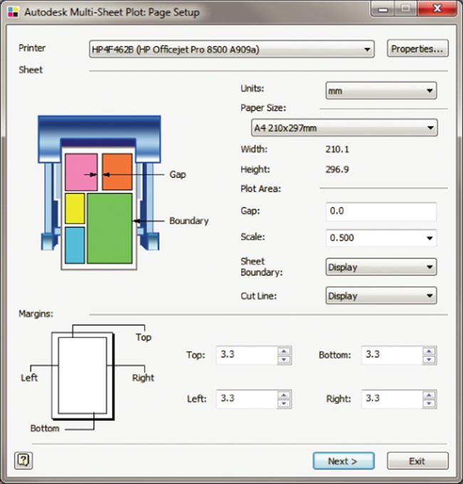
Figure 13.42 The Autodesk Multi-Sheet Plot dialog box
Using the Add-In Manager
The Add-Ins button opens an Add-In Manager dialog box that lets you select the add-ins you want to load or unload when Inventor starts. You can access this tool by choosing Start ![]() All Programs
All Programs ![]() Autodesk
Autodesk ![]() Autodesk Inventor 2015
Autodesk Inventor 2015 ![]() Tools or, when in Inventor, by selecting the Tools tab and clicking the Add-Ins button on the Options panel. Once the Add-In Manager dialog box is open, click the add-in in the Available Add-Ins area, and at the bottom of the dialog box under Load Behavior, deselect the Loaded/Unloaded option to unload it.
Tools or, when in Inventor, by selecting the Tools tab and clicking the Add-Ins button on the Options panel. Once the Add-In Manager dialog box is open, click the add-in in the Available Add-Ins area, and at the bottom of the dialog box under Load Behavior, deselect the Loaded/Unloaded option to unload it.
Using the Add-In Manager to Speed Inventor Load Time
If there are add-ins you know you do not use, you can use the Add-In Manager to prevent them from loading when Inventor loads. This will slightly speed up the load time (and reduce the amount of RAM Inventor uses). Be sure you understand what specific add-ins do because some are required for the proper operation of the software.
Using the Project Editor
Selecting the Project Editor tool opens a dialog box for the Inventor Project Editor. This is similar to the dialog box that opens after you select the Get Started tab and click Projects in Inventor. You can select each project, make changes to it, and save it without having to open Inventor. You can access this tool by choosing Start ![]() All Programs
All Programs ![]() Autodesk
Autodesk ![]() Autodesk Inventor 2015
Autodesk Inventor 2015 ![]() Tools or by right-clicking any IPJ file from Windows Explorer and choosing Edit. Project files can also be edited from within Inventor by selecting the Get Started tab and clicking the Projects button.
Tools or by right-clicking any IPJ file from Windows Explorer and choosing Edit. Project files can also be edited from within Inventor by selecting the Get Started tab and clicking the Projects button.
The Bottom Line
1. Take your models from Inventor to the Autodesk Building Systems program. If you frequently need to take your Inventor models to ABS, BIM Exchange can help you in this process with three simple steps. Inventor provides a variety of ways to simplify the model and author it. Such models can be published in ABS.
1. Master It Describe the basic steps involved in moving Inventor models to Autodesk Building Systems.
2. Create AutoLimits (design sensors). You use AutoLimits to monitor design parameters in which you are interested.
1. Master It You want to use AutoLimits for every dimension in your model. How many AutoLimits can you use at once?
3. Manage design data efficiently using Inventor tools. There are different tools for managing design data, which is typically distributed across part, assembly, and drawing files. You can associate Excel spreadsheets, text files, Word documents, and so on, with these tools.
1. Master It Name some of the Inventor tools for managing design data. Describe what each one does and how to initiate it.
4. Manage styles. You can use the Style Library Manager to organize your styles to keep them simple and clean.
1. Master It Styles normally need to be copied, edited, and deleted. How do you manage your styles? How can you create a central repository of styles?
5. Create expressions with iProperties. Property fields can be concatenated to produce desired customized information in BOM and parts lists. For example, you can break down your parts by stock size to be used in your BOM with associativity to model parameters.
1. Master It How do you create and manage expressions for iProperties?
6. Give feedback to Autodesk. You can participate in the Customer Involvement Program (CIP). Customer error reporting (CER) helps Autodesk know about any issue you might experience.
1. Master It You have a repeatable crash that you suspect is related to a specific file or a specific machine and want to know whether Autodesk can help you determine this.
All materials on the site are licensed Creative Commons Attribution-Sharealike 3.0 Unported CC BY-SA 3.0 & GNU Free Documentation License (GFDL)
If you are the copyright holder of any material contained on our site and intend to remove it, please contact our site administrator for approval.
© 2016-2026 All site design rights belong to S.Y.A.