Mastering Autodesk Inventor 2015 and Autodesk Inventor LT 2015 (2014)
Chapter 4. Basic Modeling Techniques
This chapter covers the principles of creating a 3D parametric part with the Autodesk® Inventor® and Autodesk® Inventor LT™ programs, which makes it one of the most important chapters in this book. You'll start by looking at the general options and settings associated with Inventor and part files and then move on to a basic exercise exploring the fundamentals of creating parametric models. Then you'll take a deeper look at the options found in the primary feature tools.
All the skills in this chapter are primarily based on creating a single part, whether in a single-part file or in the context of an assembly file. Do yourself a favor and learn or review these basics before jumping into the more complex features.
In this chapter, you'll learn to
· Configure options and settings for part modeling
· Create basic part features
· Use the Extrude tool
· Create revolved parts and thread features
· Create work features
· Use the Fillet tool
· Create intelligent hole features
· Bend parts
Exploring Application Options and Settings for Part Modeling
As in previous chapters, you should make sure your settings in the Application Options dialog box match the approach we're using in this book. This will ensure that the examples you work on will match the results you see here.
Specifying Global Settings
You maintain global settings for Inventor within the Application Options dialog box. For this section of the chapter, you will be concentrating on the Part tab, which allows you to maintain part-specific settings. You can adjust the application settings as follows:
1. On the Tools tab, click Application Options.
2. Choose the Part tab, as shown in Figure 4.1.
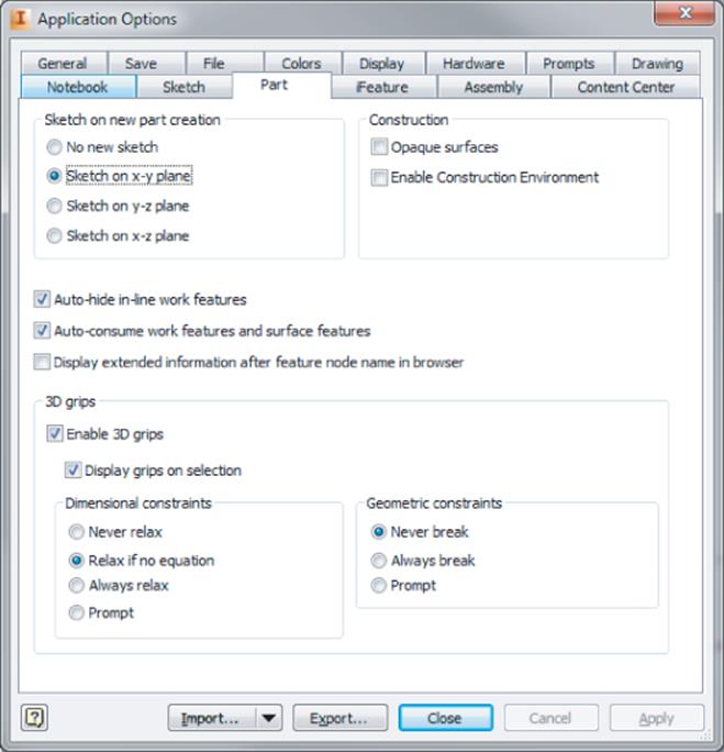
Figure 4.1 The Part tab
The Part tab settings have the following functions:
1. Sketch On New Part Creation This section allows you to predetermine the origin plane in which to place the first sketch. If No New Sketch is selected, Inventor will create a new part file without an initial sketch. You can then determine the origin plane for the first sketch.
2. Construction The Opaque Surfaces setting determines whether created surfaces will be translucent by default or as opaque as parts are. The Enable Construction Environment setting allows you to work with the construction environment tools when repairing imported surface models.
3. Auto-Hide In-Line Work Features This option allows automatic hiding of a work feature when it is consumed by another work feature. For instance, if you create a work plane by clicking a work axis and a work point, the work axis and work point will be stacked under the work plane in the browser.
4. Auto-Consume Work Features And Surface Features This option allows Inventor to consume surfaces when converted to a solid in addition to consuming work features.
5. Display Extended Information After Feature Node Name In Browser This option allows you to see more information about each browser feature. In addition to the names of part features, the size and settings of the feature will be shown to allow better identification of the part features. This option can be toggled on and off from the Browser Filters menu as well as through the Application Options dialog box. Be aware that you cannot edit the content or format of the feature name extensions.
6. 3D Grips These settings affect how 3D grips can modify a part file. In normal use, you can modify part features by selecting and dragging a 3D grip. If a dimension is controlling the feature, the dimension will update to reflect the changes in the part.
If Never Relax is selected, any features controlled by the dimension will not change.
When Relax If No Equation is selected, a dimension value will update unless that dimension value is determined by an equation. Selecting Always Relax will always allow the use of 3D grips, even when controlled by an equation. The Prompt setting will prompt you to accept any changes during drag operations.
The settings in the Geometric Constraints area control how constraints will be handled during drag operations. Never Break prevents grip editing when sketch constraints are controlling a sketch. Always Break allows constraints to be broken as required during grip edits. The Prompt setting asks you to make a decision on a case-by-case basis for each grip edit.
Specifying Document-Specific Settings
To change the options in a specific part file, you'll need to access the part's Document Settings dialog box by selecting the Tools tab and clicking Document Settings while that part is open. The Document Settings dialog box that opens allows specific settings for an individual file in the following areas:
· Lighting styles
· Materials
· Units
· Modeling dimension display values
· Individual sketch settings
· Model values
· Bill of materials (BOM)
· Default tolerances
Any changes made in the part's Document Settings dialog box will be applied only to the current document. Current document settings will not affect the settings in other parts within an assembly.
The Standard Tab
Figure 4.2 shows the part's Document Settings dialog box with the Standard tab active. The Standard tab controls the active lighting style of the current graphics window. In addition, you can set the physical material properties and the display appearance of the current part here.
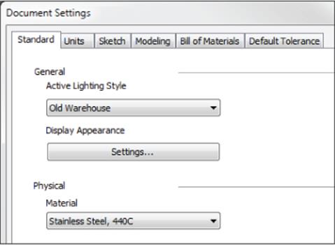
Figure 4.2 The Standard tab in a part's Document Settings dialog box
The lighting style is selected from a preset list in the drop-down menu, as is the physical material. The display appearance is configured by clicking the Settings button and adjusting the various settings in the resulting dialog box. To use the display appearance settings configured in the part file, you must first select the Display tab of the Application Options dialog box and select Use Document Settings.
The Units Tab
The settings on the Units tab allow you to change the unit specification values, as shown in Figure 4.3. For example, you could open a metric (mm) part and change the input settings to inches.
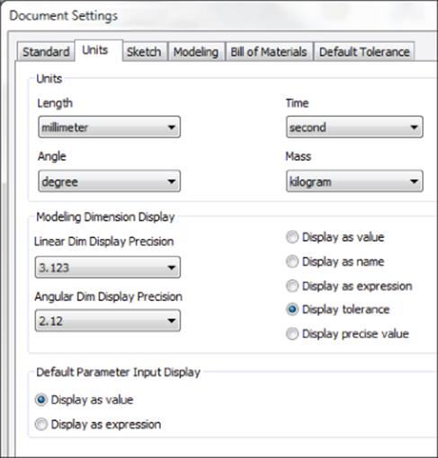
Figure 4.3 The Units tab in Document Settings
The Units tab settings have the following functions:
1. Modeling Dimension Display These settings allow you to define the model dimension's display precision by the number of decimal places and define how that dimension will be displayed. Many people prefer the Display As Expression setting because it shows the dimension name along with any expression that exists in the dimension; if no expression exists, the dimension name and dimension value are displayed.
2. Default Parameter Input Display These settings allow you to see the parameter name in the input box when you're editing a dimension or feature input. Figure 4.4 shows the option set to display as the expression on the left and set to display as the value on the right. You can also access this setting from the context menu.
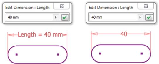
Figure 4.4 Default parameter input display
The Sketch Tab
On the Sketch tab, shown in Figure 4.5, you can adjust how the 2D sketch tools work and appear in an active sketch. In addition, you can change the preset value for Auto-Bend Radius in the 3D Sketch area.
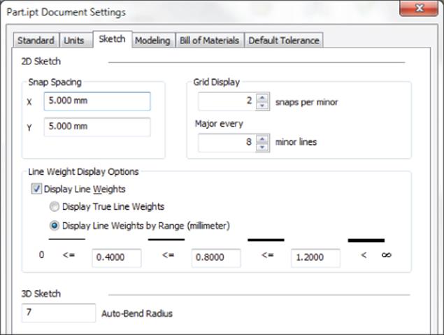
Figure 4.5 Sketch tab in Document Settings
Here are the Sketch tab settings along with a description of their functions:
1. Snap Spacing This option allows you to set the spacing between snap points to assist with precise layouts. For instance, if you are using Frame Generator to create a steel frame with uprights at 2000 mm on center, you might set the snap spacing to 2000 mm and then on the Sketch tab in the Application Options dialog box, set the sketch to Snap To Grid. Then, when creating your skeletal base sketch, you can set line segments and spacing to 2000 mm with precision.
2. Grid Display These settings allow you to set the major and minor grid spacing. If Snaps Per Minor were set to 2 with the 2000 mm snap spacing used in the previous example, the spacing between grid lines would be 4000 mm. If Major Every were set to 5, distance between the major grid lines would be 20,000 mm. To display grid lines, you select the Sketch tab in the Application Options dialog box.
3. Line Weight Display Options These options allow the display of unique line weights in model sketches. Note that this does not influence line weights in printed model sketches. Display True Line Weights displays line weights on-screen as they would appear on paper regardless of the on-screen zoom level. Display Line Weights By Range displays line weight according to the entered values.
4. 3D Sketch This area contains only one setting, Auto-Bend Radius. When creating a 3D line, you can turn on the Auto-Bend Radius option and have intersecting line corners automatically rounded. This setting controls the default radius at which bends are created. Once they are made, the bends can be edited to a different value.
The Modeling Tab
Figure 4.6 shows the Modeling tab, which allows changes to the behavior while modeling the current active part. Note that if you are using Inventor LT, some of these settings might vary or might not be present.
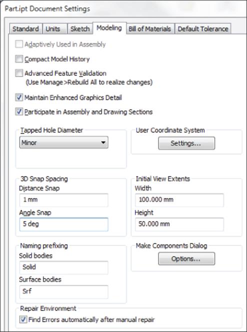
Figure 4.6 Modeling tab in Document Settings
Here are the settings found on the Modeling tab of the Document Settings dialog box:
1. Adaptively Used In Assembly This option is available only when a part is adaptive. When it is deselected, an adaptive part becomes static. This setting can also be controlled by right-clicking an adaptive part in the assembly browser.
2. Compact Model History This option allows Inventor to purge all rollback document history when you save the current file. Compacting the model history improves performance in large assembly files. You should select this option only when performance is affected in large assembly files or when existing disk space is limited.
3. Advanced Feature Validation This option permits Inventor to use a different algorithm to compute features. Using this option can produce more accurate feature results in rare cases such as Shell, Draft, Thicken, and Offset features. However, this option is slower in calculation than the default option and should be used only on rare occasions where the accuracy of the model may be in question.
4. Maintain Enhanced Graphics Detail This option enables graphics information to be saved with the file on disk. This information is used in the graphics display if the display quality is set to Smoother in the Application Options dialog box.
5. Participate In Assembly And Drawing Sections When this option is not selected, the part will default to None in the section participation settings of an assembly or drawing section view. However, you can adjust each instance of the part to section or not section as needed. For instance, if you created a part file for an O-ring and intended to use it in the design of several shaft assemblies, you could deselect this option in the O-ring file to ensure that the O-ring remained unsectioned in the section drawing views of the shafts you used the O-ring on. If you needed to show a particular section view of the shaft assembly with all parts sectioned, you would do so by setting the section participation settings for the O-ring to section in that one section view of the drawing.
6. Tapped Hole Diameter This option determines how the size of tapped hole features are controlled. Thread representations in drawings are generated correctly only when Tapped Hole Diameter is set to Minor.
7. User Coordinate System Click the Settings button to access the UCS Settings dialog box, where the UCS naming prefix can be set, the default plane defined, and the visibility of UCS and its features determined.
8. 3D Snap Spacing These options establish the spacing between snap points in 3D sketches. The settings also control the snap precision when the Move Bodies tool is used to free-drag a solid body.
9. Initial View Extents These options set the initial visible height and width of the graphics window when you're creating a model from a template. For instance, if you create a lot of steel frames, you may find it helpful to create a template with the setting adjusted so that your initial sketch is not always zoomed in to a very small area. Configure these settings in your template files to affect new files. You can set the initial height and width of the graphics window. The settings affect only the initial sketch when a template is used. When you're creating a secondary sketch or opening an existing part, the view is controlled by the size of the part.
10.Naming Prefixing These options set the default file-naming convention for parts generated from multi-body part designs. These tools are covered in Chapter 5, “Advanced Modeling Techniques.”
11.Make Components Dialog Clicking Options in the Make Components Dialog area opens the Make Components Options dialog box. The Make Components settings shown in the options dialog box are specific to the active project. These options are employed when creating multi-body parts, as described in Chapter 5.
The Bill Of Materials Tab
The Bill Of Materials tab determines the structure of the current file and how that structure relates to the bill of materials in an Inventor assembly. Figure 4.7 shows the default settings for structure and quantity.
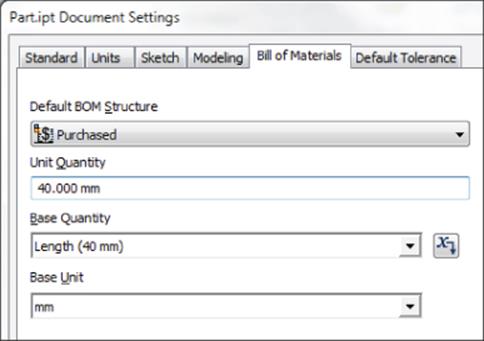
Figure 4.7 Bill Of Materials tab in Document Settings
You can add BOM structure properties to individual parts in the Document Settings dialog box. Figure 4.7 shows the choices available in a model or assembly file for setting individual file properties.
Here are the details:
1. Normal These components are given an item number and included in quantity calculations. The placement of normal parts in the bill of materials is determined by the parent assembly properties. A normal subassembly may be composed of any combination of inseparable, phantom, purchased, and reference parts without having any effect on how those parts are listed in the BOM. Normal is used for most components.
2. Inseparable These components are assemblies that allow the inclusion of press-fit, glued, welded, or riveted components that might be damaged if taken apart. A good example is a hinge that is fully assembled but should be listed in the BOM as a single part. Although the Inseparable structure is listed in the part's Document Settings dialog box, it is intended as an assembly property.
3. Purchased These components are parts that are not normally fabricated or manufactured by your company but instead purchased from vendors. Any purchased component, whether part or assembly, will be listed in a parts-only parts list. A purchased component assembly will not normally have the component parts listed in the BOM because that component will be purchased as a single unit.
4. Phantom These components exist in the design but are not included as specific line items in the BOM. A construction assembly that exists as a container (subassembly) within a higher-level assembly, simply to hold a number of components together for assembly purposes, can be set to Phantom. When this assembly is set to Phantom, it will not appear in the parts list; however, the parts included within the construction assembly will be listed as individual parts. Phantom components are ignored by the BOM. No item number is assigned, and no quantity calculations are performed on the phantom assembly. However, the quantity of individual parts contained within the phantom assembly will be multiplied by the quantity of the phantom component included in the top-level assembly.
5. Reference These components are used to provide reference information within an assembly design. An example of a reference part might be a product container placed in a conveyor assembly. The conveyor components are the parts and assemblies you are designing, but the container is required to ensure the clearance and function of your design. In a drawing, reference parts will be indicated in the view as hidden line geometry. Reference components are excluded from the BOM and are excluded from quantity, mass, and value calculations.
6. Base Quantity Use this to change how the part's Base Quantity property is displayed in the BOM or parts list. You can change the value from Each to any parameter, such as one called Length. You will find that components generated by the Frame Generator tools are automatically set to use a length parameter for the base quantity. Once a parameter is selected, you can change the Base Unit, from mm to M for example.
The Default Tolerance Tab
Figure 4.8 shows the Default Tolerance settings. Creating tolerance values affects sketches and parts only. When you add tolerance values to a part file, you can select either Use Standard Tolerancing Values or Export Standard Tolerance Values, or you can select both options.
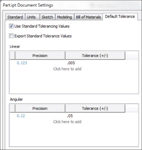
Figure 4.8 Default Tolerance tab in Document Settings
You can select the Use Standard Tolerancing Values box to use the precision and tolerance values set in this dialog box. You can select the Export Standard Tolerance Values box to export tolerance dimensions to the drawing environment.
Once you've selected an option, you can then add linear or angular tolerance values. You can add any number of tolerance values by precision to this part. When you have added your values to the part, click the Apply button to stay in the dialog box and apply the new settings to this tab, or click the OK button to apply the settings and exit the dialog box. Chapter 5 covers the use and setup of part tolerances in more detail.
Key Concepts for Creating Basic Part Features
Inventor 3D part modeling is based on the principle of creating a base feature and then adding features to the base feature to build a more complex part. Figure 4.9 illustrates the basic workflow for creating a part composed of multiple features.
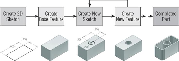
Figure 4.9 Part-creation workflow
Create Your Own Template Files
This may seem like a lot of settings, and it's true there are a lot, but you need to set them only once. Open a template, adjust all your settings the way you want them for a particular type of part (for instance, an inch unit part), and then use the Save Copy As Template option. Your settings will then be available in a template when you create a new part. Make another template for metric parts. Make another for sheet-metal parts, and so on, as you like. You can make as many as you think you'll use, each with its own set of document settings specific to the template.
A good idea is to make a folder in your template directory named, for example, My Templates, and store all your templates in it. This folder (and any other folder in the template directory) will show up as a tab in the New File dialog box. This way, you will still have access to Inventor's standard templates as well as your custom templates.
You can set the template file location in two places:
· On the Tools tab of the ribbon, click Application Options and select the File tab in the dialog box that opens.
· On the Get Started tab of the ribbon, click Projects and select the Folder Options entry in the dialog box that opens.
Keep in mind that if the settings in these two locations are not the same, Inventor will use the Projects setting.
As you create parts in Inventor, keep in mind the following concepts because each will go a long way toward making your modeling endeavors more productive:
· Anchor and orient your base sketch to the 0,0,0 origins of the part file. This will make your parts much easier to manage as you go forward. The base feature will generally be the largest feature in the part, unless you have a specific reason for not making it so.
· Look for areas of your design that are likely to change and create your part features to accommodate these future edits. For example, the plate thickness might change as loads are determined throughout the rest of the design. Creating the plate sketch from the end view and then extruding the length would make it easy to modify the length of the plate but not as easy to modify the thickness. Therefore, a better choice would be to create the base sketch of the top view and extrude the thickness.
· Identify relationships between design parameters. For instance, there may be a requirement that the distance from the edge of a part to the edge of a bolt hole always has to be two times the diameter of that hole. You can set that formula directly in the distance dimension, and then whenever you change the hole diameter, the distance from the edge adjusts automatically.
· Keep an eye out for patterned and symmetrical design features. It is much easier to create and modify the first instance of a pattern than it is to edit several identical features that were created separately.
· Build logical feature dependencies. Features are considered dependent on other part geometry when you cannot delete or modify a portion of the part or feature without affecting another feature built later in the part. For example, if you were to create a simple block and then create an additional feature on that block, you could not delete the block without upsetting the new feature.
· Because fillets and chamfers often change, it is best to place them at the end of the design process as much as possible. Placing them at the beginning and then having to change them is likely to upset other features you have created afterward that might depend on the filleted or chamfered edges.
· Create simple sketches to create simple features to create complex parts. Using numerous features within a 3D model allows simplified control over modifications of the model in the future. Separate features may be suppressed or modified to alter the design without having to make changes in a complicated sketch. Instead of attempting to create all the geometry in a single sketch, analyze the proposed part first and create a simple base sketch for the first feature.

Consider Modeling vs. Machining
Although the “design as you'd manufacture” paradigm is a great philosophy to follow when creating 3D parts, there are differences between modeling and machining. One major difference is that you have the ability to add material when modeling, whereas a machining operation only takes away material. Deciding which route to take depends on what resources are available in your shop and how much time you have.
Modeling and machining are important subjects to consider when designing parts. Inventor offers a lot of features that may make it easy to design a part that might be impossible or at least very expensive to make with the tooling equipment your shop has available. In some cases, although a part may be easier to model as one piece, it might be less expensive to machine as multiple pieces. Also, consider the size of the equipment and tooling, such as end mills and drills, when creating parts. For example, in Inventor you can create very small fillets or square corners in a design, but try to machine a 0.010 inch fillet in a cavity that is 3 inches deep, and you'll likely earn a scolding from the people on the shop floor who are required to turn your design into reality.
One example for how to make a realistic design for your shop is the fixture block, as shown here. If a CNC machine center is available, this simple part is easy to model in Inventor and not a problem to create in the shop.
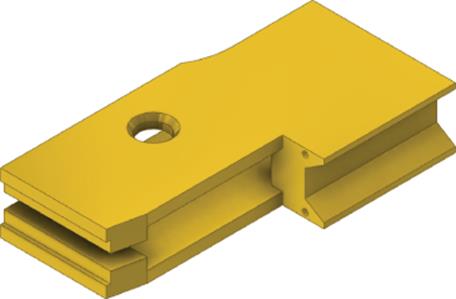
However, without a CNC approach, even this simple model might prove to be difficult and/or expensive to produce by more traditional machining techniques. Reconsidering the design to match the shop's abilities will be required. In this case, you might consider a sandwich block design of simple parts welded and fastened together to achieve the same end result, as shown here.
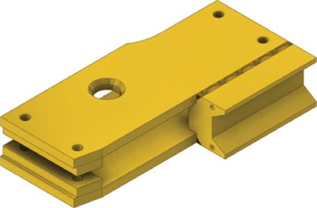
Although this might require more thought and planning on your part within Inventor, it will make the design achievable with the tools and technology at hand. Often the best resource for helping you determine what your shop's capabilities are will be the people who will be making the parts.
Simplifying Your Sketches
When learning to master creating parts in Inventor, there is probably no concept more important than the idea of creating simple sketches from which to build simple features that will add up to create complex parts. Standard 2D drafting practice requires you to place all part details or components within a single view. However, it is not good practice to use the same 2D drafting workflow within any feature-based 3D modeler. Complicated sketches can drag down sketching performance and virtually eliminate easy changes to features. Consider the part shown in Figure 4.10. This illustration shows the base sketch that is then revolved to form the shaft.
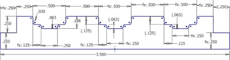
Figure 4.10 A complex sketch for a revolved part
Now compare the same part modeled using the simple-sketches approach shown in Figure 4.11.
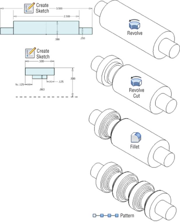
Figure 4.11 Simple sketches and placed features create a revolved part.
The version in Figure 4.10 would prove difficult to modify because of the number of sketch constraints and dimensions required to create it. Most likely a seemingly simple change would result in some part of the sketch breaking. By comparison, the version in Figure 4.11 would be easy to modify because each feature is broken out into its own sketch or placed feature.
Of course, sometimes creating a more complex sketch is required, but if you follow the simple-sketch rule of thumb, you will find Inventor much more accommodating, and you will quickly master part creation and be ready to tackle complex sketches when they are needed.
At the end of this chapter you will find an exercise that builds a part by first creating a simple sketch and constructing a base feature from it. The exercise continues adding simple features to build complexity into the part. But before you get to that exercise, you'll find several shorter exercises exploring many of the tools used to create part features. If you have not already downloaded the Chapter 4 files from www.sybex.com/go/masteringinventor2015, please refer to the “What You Will Need” section of the introduction for the download and setup instructions.
Exploring the Extrude Tool
The Extrude tool allows you to add volume to a closed sketch profile to create a 3D solid and allows you to add length to an open sketch profile to create a 2D or 3D surface. You can also use the Extrude tool to create cutouts in solids.
To truly master the Extrude tool, you have to understand several options. In the next several pages, you will open a series of files that have been set up to demonstrate the various options available to you. You can find all of these files in the Chapter 04 directory of yourMastering Inventor 2015 folder.
Marking Menus
If you have the marking menus enabled and customized, you should be prepared to interpret the instructions in this book concerning right-clicks to match what you see on-screen.
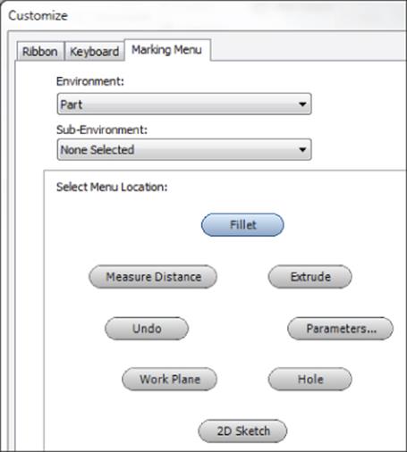
If you prefer, you can disable the marking menu and use the classic context menu by clicking the Customize button on the Tools tab. On the Marking Menu tab, you will find an option called Use Classic Context Menu.
Extruding Basic Features

The Extrude tool is often used to create base features on which other features are created. To explore the creation of a base extrude feature, follow these steps:
1. Open the file mi_4a_008.ipt.
2. Click the Extrude button on the 3D Model tab (or press E on the keyboard).
Because the sketch in this part file contains five profiles from which you can choose, the Extrude tool requires you to select the profile or profiles you want to extrude. Note that the large, dashed circle in the center of the hexagon is not recognized as a profile because it is set as a construction line in the sketch.
Use Sketch Center Points to Create Profiles
In Sketch1 of mi_4a_008.ipt, you might have noticed the presence of four sketch center points at the intersection of the hexagon and the two circles. Sketch center points placed at the intersection of overlapping profiles allow Inventor to see the profile as separate sketch profiles, without the need to split or trim the sketch geometry.
3. Hover your cursor over each profile to see it highlight.
4. Click in the center of the hexagon, and you will see a preview of the extrusion that will be created from this profile.
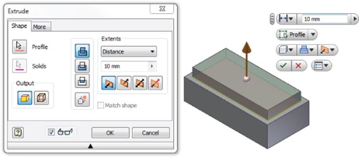
5. Click and drag the arrow at the center of the preview to change the extrusion distance and/or direction.
6. Use the Flip button to change the direction of the extrusion so that it goes down away from the sketch, as shown in Figure 4.12.
7. Set the extrude Distance to 25 mm and then click the OK button.
Notice that a feature called Extrusion1 has been created in the Model browser tree. If you click the plus symbol next to it, you'll see that Sketch1 is listed under it, because Extrusion1 consumes Sketch1.
8. Locate Sketch2 in the Model browser and right-click it; then select Visibility to turn this sketch on.
9. Click the Extrude button on the 3D Model tab (or press E on the keyboard).
10.Set the extrude Distance to 60 mm and ensure the direction is facing up, as shown in Figure 4.13; then click the OK button.
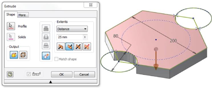
Figure 4.12 Creating a base extrude feature
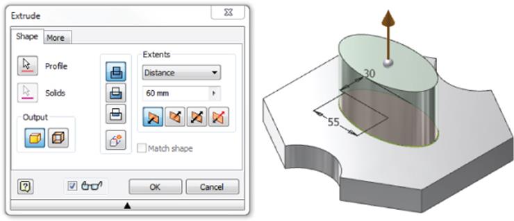
Figure 4.13 Creating a secondary extrude feature
Creating basic extrusions from a sketch profile is quite a simple operation and one that you will use often in creating your designs. You can close the part without saving changes and continue to explore the Extrude option.
Direct Manipulation Tools
The Direct Manipulation toolset is a set of user interface tools enabling you to modify a model while viewing the changes in real time. The buttons on the in-canvas display correspond to the buttons and inputs found in dialog boxes and menus. You can choose to use the Direct Manipulation tools, or you can use the traditional dialog boxes and menus to achieve the same result.
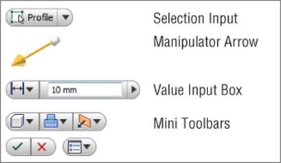
The Direct Manipulation In-Canvas Display consists of selection tags, manipulator arrows, value input boxes, and mini-toolbars.
Once you become comfortable with the Direct Manipulation tools, you can use the arrow at the bottom of the dialog box of each tool and choose to roll it up to save screen space. Note that you cannot disable the Direct Manipulation tools.
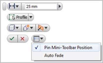
One tip to be aware of is the ability to pin the Direct Manipulation mini-tools in place. For instance, you can drag the mini-toolbars to the upper-right corner of your graphics screen, near the ViewCube®, and then use the options menu pull-down button to select the Pin Mini-Toolbar Position option. Doing so will ensure that these tools will appear in this location each time you use the tool.
Editing an Extrusion Feature
Once you create extrusions, you can quickly and easily modify them by using the same inputs used to create the original feature. In the following exercise, you'll open an existing part and edit an extrusion feature in order to change the length of the part:
1. Open the file mi_4a_009.ipt.
2. Locate the feature named Extrusion2 in the Model browser and then double-click it or right-click and choose Edit Feature.
3. Set the Distance to 100 mm and then click the OK button.
4. Expand the Extrusion1 node in the browser to reveal Sketch1.
5. Right-click it and choose Edit Sketch, or double-click it to edit the sketch.
6. Edit the Hex_Size dimension by right-clicking or double-clicking it; then set it to 30 mm.
7. Click the Finish Sketch button to exit the sketch and set the change.
Making edits to existing extrusions features is as simple as editing the extrusion feature or the sketches used to create them. You can close the part without saving changes and continue to explore the Extrude option.
Extruding with Cut and Taper
You can use the Extrude tool's Cut option to remove material from your parts. Although you may think of this as a tool to create holes, keep in mind that Inventor's Hole tool is the better choice to create standard holes because of the advanced detailing functions that accompany the Hole tool. With that said, the Cut option in the Extrude tool will allow you to cut material using any sketched profile that you might come up with. To explore the Taper option in the Extrude tool, follow these steps:
1. Open the file mi_4a_010.ipt.
2. Click Extrude on the 3D Model tab (or press E on the keyboard).
3. Select the rectangle shape for the extrude profile (if it does not select automatically) and set the distance to 20 mm.
4. Choose the Cut option and just drag the manipulator arrow down into the part; notice that the preview turns red and the direction automatically switches. Change the direction so the preview is going up out of the part and then click the OK button.
5. Note that an error is generated, and it states that the feature you specified did not change the number of faces. Keep this in mind as you use the Extrude tool. Inventor will generally set the correct direction for you, but occasionally you might need to set the direction manually. Click the Edit button to return to the extrude options.
6. Change the direction again so you are indeed cutting the part and adjust the distance to 20 mm as required.
7. Click the sphere on the manipulator arrow or click the More tab, as shown in Figure 4.14.
8. Enter −12 in the Taper input box and click the OK button to create a tapered cut. When finished, you can close the part without saving changes.
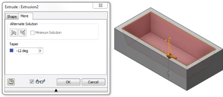
Figure 4.14 A tapered cut extrusion
Extruding with Intersect
So far you have created extrusion features using the Join option and the Cut option. Next, you will use the Intersect option of the Extrude tool to modify an existing solid. The Intersect option allows you to select a sketch profile and keep only material that intersects the existing solid and the sketch profile. You can create complex shapes by sketching an intersect profile and then using the extrude Intersect option to keep the combined volume of the existing solid and the sketch profile, as shown here:
1. Open the file mi_4a_012.ipt.
2. Click Extrude on the 3D Model tab (or press E on the keyboard).
Rather than cutting the small profiles out of the existing part, you'll use the Intersect option to discard all areas of the part that are not common between the existing part and the current sketch.
3. Select the large H-shaped sketch profile.
4. Change the Extents drop-down from Distance to All.
5. Click the Intersect button, make sure the extrude direction is going down through the existing part, and then click the OK button.
6. Click the end-of-part marker in the Model browser and drag it down below the sketch called Slot Locations so the Slot Locations sketch is visible and available for use.
This sketch consists of several small slots. You could select each slot and cut it from the existing part, but doing so would be time-consuming and subject to a missed selection, which will give you errant results. Instead, you'll use the Intersect option to choose the area between the slots.
7. Click Extrude on the 3D Model tab (or press E on the keyboard).
8. Select anywhere in the rectangular sketch profile so the selection results in a rectangle with the slots are omitted.
9. Change the Extents drop-down from Distance to All.
10.Click the Intersect button, make sure the extrude direction is going down through the existing part, and then click the OK button.
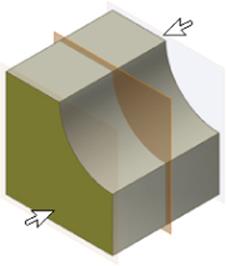
Figure 4.15 shows the progress of the part using the Intersect option to refine its shape.
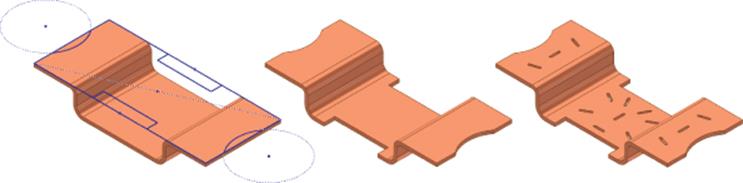
Figure 4.15 A complex shape generated using the intersect extrusion
For another example of using the Intersect option, take a look at using it to create the tapered corners on a common hex head bolt, as demonstrated in the following exercise:
1. Open the file mi_4a_013.ipt.
2. Click Extrude on the 3D Model tab (or press E on the keyboard).
3. Select the visible sketch for the extrude profile (if it's not automatically selected).
4. Set the distance to 100 mm.
5. Click the Intersect button, and make sure the extrude direction is correct. You want the extrusion going down though the bolt head and shaft.
6. Click the sphere on the manipulator arrow or click the More tab in the dialog box.
7. Enter 30 in the Taper input box, as shown in Figure 4.16, and click the OK button.
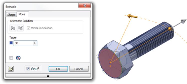
Figure 4.16 A tapered intersection extrusion
Your extrude options create a cone with a 30° taper, and the Intersect option keeps only the volume of the part shared by the existing features and the intersect cone feature, in this case the entire bolt except the tapered corners of the hex head. When finished, you can close the part without saving changes.
Extruding Surfaces from Open Profiles
In addition to creating solids with the Extrude tool, you can create surfaces. If the profile is open and there is no other geometry to relate to, the surface solution is automatically selected. For closed profiles, you are required to switch the output from solid to surface manually, as shown here:
1. Open the file mi_4a_014.ipt.
2. Click the Extrude button on the 3D Model tab (or press E on the keyboard).
3. The visible shape will automatically be selected because it is the only available profile. Because it is found to be an open profile, the Surface output is automatically selected as well.
4. Change the distance to 25 mm.
5. Set the direction arrow to the symmetric option so that the surface is extruded in both directions from the profile, as shown in Figure 4.17. Then click the OK button.
6. To explore how to create a surface extrusion from a closed profile, right-click Sketch2 in the browser and turn on the visibility.
7. Select the Extrude tool, and notice that Inventor automatically selects the profile and sets the output to Solid in the dialog box.
8. Click the Surface button to change the output to an extruded surface and then change the Extents option to To.
9. Doing so allows you to specify a point or surface to extrude to. You might notice that the surface created in the previous step was created in two halves. Select the arc-shaped half (rather than the spline-shaped half), and notice that the preview terminates as if the arc half-wrapped around.
10.Deselect the check box next to the To selection arrow (the Terminate Feature On Extended Face check box), and you will notice that the preview terminates at the farthest extent of the selected surface, matching the spline shape.
If you receive an error stating that the attempted surface did not terminate the tool body, review step 5 and ensure that your first extrusion was set to extrude symmetrically from the original sketch.
11.Click the OK button to create the extruded surface.
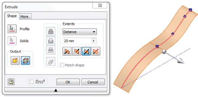
Figure 4.17 Extruding an open profile sketch to create a surface
Figure 4.18 compares the two termination solutions when using the To option. Keep in mind that although this example used surface extrusions, the To option works the same for solids. You can close the file without saving changes.
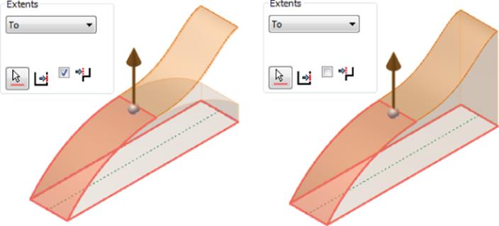
Figure 4.18 Extruding a surface to terminate at the farthest extent of another surface
Extruding Solids from Open Profiles
In addition to extruding surfaces from open profiles, you can extrude solids, provided sufficient geometry is present to allow the open profile to solve correctly. This technique employs the Match Shape option and is the default solution when an open profile is selected in the Extrude tool while the solid output is selected. Follow these steps:
1. Open the file mi_4a_016.ipt.
2. Click the Extrude button on the 3D Model tab (or press E on the keyboard).
3. Click the arc profile, and notice that the Match Shape check box is automatically selected in the dialog box; in addition, the preview has extended the arc down toward the plate to provide a closed profile.
4. Click in the highlighted profile to select it.
5. Change the Extents drop-down to Distance and enter 60 mm.
6. Set the direction to go into the base plate feature and click the OK button. Your result should look like Figure 4.19. You can close the file without saving changes.
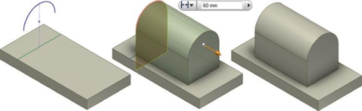
Figure 4.19 Extruding an open profile
To take a look at the Match Shape option and how it can be used to change the output, you'll open a file that has two possible solutions for the final matched shape. One solution willmatch the shape of the existing geometry, and the other will not. Follow these steps to see how this works:
1. Open the file mi_4a_018.ipt.
2. Click the Extrude button on the 3D Model tab (or press E on the keyboard).
3. Click the visible profile sketch in the center of the part.
4. You'll notice that Inventor attempts to create a closed profile from this open profile by extending the profile past the extents of the existing geometry. Select the profile on the side with the grid feature.
5. Change the Extents drop-down to Distance, enter 1 mm, and click the OK button. Notice how the extrusion fills the shape of the part.
6. Edit the extrusion you just created, and deselect the Match Shape box in the dialog box. Then click the OK button.
7. You'll notice that the extrusion runs through the grid feature, ignoring the shape.
Figure 4.20 compares the results of an open profile extrusion with and without the Match Shape option selected. You can close the file without saving changes.
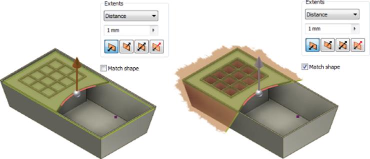
Figure 4.20 Match Shape option for open profile extrudes
Extruding with To
It is often helpful to extrude to existing geometry rather than entering a distance value. In this way, if the existing feature changes, so too will your extrusion. When you use the Extrude To option, you can extrude to faces and vertices as well as work planes and work points. In the following exercise, you'll explore the Extrude To option:
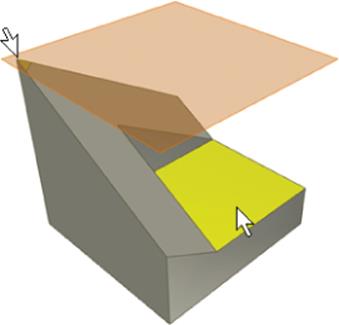
1. Open the file mi_4a_020.ipt.
2. Click the Extrude button on the 3D Model tab (or press E on the keyboard).
3. For the profile, select one of the rectangular profiles.
4. Change the Extents drop-down from Distance to To.
5. Select the yellow face, and click the OK button.
You will receive an error stating that the termination plane does not completely terminate the profile, because of the way that the yellow face would wrap around in a circle if extended.
6. Click the Edit button in the error dialog box to return to the Extrude dialog box.
7. Uncheck the Terminate Feature On Extended Face check box in the Extents area, as shown in Figure 4.21, and then click the OK button.
8. Use the Extrude tool and select the remaining rectangle.
9. Change the Extents drop-down from Distance to To.
10.Select the red face, and you will see that the preview terminates along the extended red face.
11.Uncheck the Terminate Feature On Extended Face check box in the Extents area, and you see the preview extend to the yellow face.
12.Click the OK button to create the extrusion. You can close the file without saving changes.
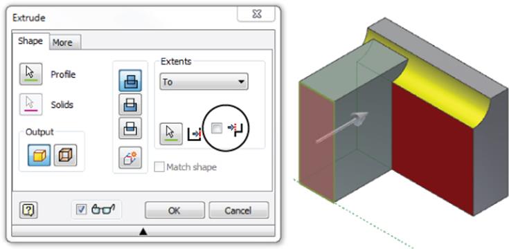
Figure 4.21 Extruding to an extended face
Although in this case the results of the two extrusion features are the same, you can see that the selected termination face and the termination check box can provide different results when used in combination.
Follow these steps to take a look at some other Extrude To options:
1. Open the file mi_4a_022.ipt.
2. Click the Extrude button on the 3D Model tab (or press E on the keyboard).
3. For the profile, select one of the ellipse-shaped profiles.
4. Change the Extents drop-down from Distance to To. Select the yellow face and ensure that the Terminate Feature On Extended Face check box is checked. In this case, you would receive an error if this check box were not selected. Figure 4.22 shows the correct selections.
5. Click the OK button, and you'll see that the ellipse face takes on the angle of the face to which you extruded.
6. Use the Extrude tool again, select the other ellipse profile, and change the Extents drop-down from Distance to To. This time select the work point for the terminating object and click the OK button.
7. You'll see that the ellipse extrudes up to the work point height, as shown in Figure 4.23.
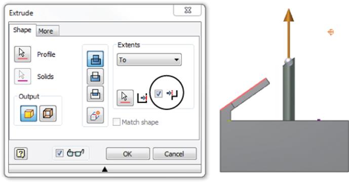
Figure 4.22 Extruding to a face
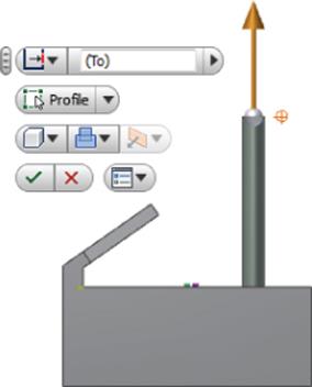
Figure 4.23 Extruding to a point
Although in this case you've used a work point to extrude to, often you can use the vertex point of an existing feature to extrude to. Feel free to experiment with this part and extrude shapes to an existing point on the yellow face. When finished, you can close the file without saving changes.
Extruding with the Minimum Solution Option
Often when extruding to a cylindrical face, you will need to set the extrusion to solve for the minimum solution since the face is continuous all the way around. To do this, follow these steps:
1. Open the file mi_4a_024.ipt.
2. Click the Extrude button on the 3D Model tab (or press E on the keyboard).
3. For the profile, select the hex-shaped profile.
4. Change the Extents drop-down from Distance to To, select the outside face of the cylinder, and then click the OK button.
You will notice that the hex shape stops at the closest face of the pipe. This is because the Minimum Solution option is the default. However, if the goal were to extend the profile to the farthest extent of the cylindrical face, you would need to adjust the settings to the farthest extent of the cylindrical face.
5. To fix this, edit the extrusion you just created and click the More tab (or click the sphere on the on-screen manipulator arrow).
6. On the More tab, select the Minimum Solution check box, as shown in Figure 4.24, and then click the OK button.
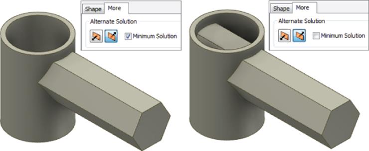
Figure 4.24 Extruding to the minimum solution
You'll see that without the Minimum Solution option selected, the extrusion extends to the far side of the selected face. You can close the file without saving changes.
Extruding with To Next
Similar to extruding to a selected entity, you can use the To Next option and let Inventor automatically select the next available surface or face for you. It should be noted that solutions with through voids may not work with this option. To explore the Extrude tool's To Next option, follow these steps:
1. Open the file mi_4a_026.ipt.
2. Click the Extrude button on the 3D Model tab (or press E on the keyboard).
3. For the profile, select the rectangular profile marked Profile1.
4. Change the Extents drop-down from Distance to To Next, and click the OK button.
5. Repeat the same steps for Profile2. When you click the OK button, you will receive an error because the extrusion cannot build to this solution.
6. In the error message dialog box, click the Edit button and then set the extrude extents to To.
7. Select the back (yellow) face for the face to extrude to and then click the OK button.
Oftentimes the geometry may require a bit of experimenting to achieve the solution you want. Just knowing the abilities and limitations of each option goes a long way toward knowing how to proceed. You can close the file without saving changes. Figure 4.25 shows the results of using the To Next option.
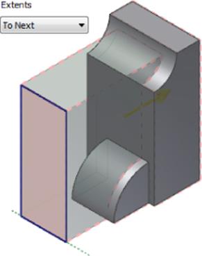
Figure 4.25 Extruding with To Next
Extruding Between
You may need to define the beginning and the end of an extrusion that are not common to your sketch plane. To do this, you can use the Between option:
1. Open the file mi_4a_028.ipt.
2. Click the Extrude button on the 3D Model tab (or press E on the keyboard).
3. For the profile, select Circle.
4. Change the Extents drop-down from Distance to Between.
5. Select both pipe-shaped pieces to define the From and To options.
6. Because you are extruding to hollow objects, you'll need to use the Minimum Solution option. Click the More tab, and make sure the Minimum Solution check box is selected.
7. Flip the direction using a direction button next to the Minimum Solution check box. Click the OK button.
Figure 4.26 shows the results of using the Between extents option. You can close the file without saving changes.
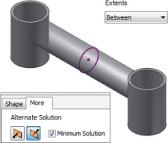
Figure 4.26 Extruding with Between
Extruding Multi-body Solids
You may have noticed a couple of other buttons in the Extrude dialog box, one called Solids and the other called New Solid. Figure 4.27 shows both buttons in the dialog box. These options allow you to create separate solid bodies within the part or choose which existing solid bodies to modify.
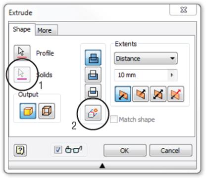
Figure 4.27 Multi-body solid options
The first option allows you to select the solids you want to modify. Use this when selecting multiple solid bodies in which to create a cutout feature, for instance.
When selected, the second option allows the Extrude tool to create a separate solid body, rather than creating a feature of an existing solid. Separate solids can then be moved, rotated, colored, and modified individually.
To explore the multi-body extrude options, follow these steps:
1. Open the file mi_4a_030.ipt.
2. Click the Extrude button on the 3D Model tab (or press E on the keyboard).
3. For the profile, select the visible rectangular sketch profile (if it is not automatically selected).
4. Change the Extents drop-down from Distance to To and select the yellow face on the existing part feature.
5. Click the New Solid button, as shown in Figure 4.28, to set this extrusion as a separate solid body; then click the OK button.
Because you used the New Solid option, you now have a part file with two separate solid bodies. You can expand the Solid Bodies folder in the browser to identify each one, as shown in Figure 4.29. Currently, the second solid interferes with the first and needs to be dovetailed to fit.
6. On the Modify panel of the 3D Model tab, click the Combine button.
7. Choose the new solid for the Base selection and choose the original solid (the one with the yellow face) as the Toolbody selection.
8. Set the operation to Cut (middle button).
9. Select the Keep Toolbody check box and then click the OK button.
You should see the original solid disappear and the new solid result in a dovetail where it intersected with the first. Expand the Solid Bodies folder and ensure that you have two solid bodies still. If not, use the Undo button and repeat steps 6 through 9.
10.Right-click either of the solids and choose Show All to turn the visibility of the solid back on.
Next you'll use an existing sketch to cut a notched edge into both of the solid bodies at the same time.
11.Locate the sketch named Base Inset Sketch in the Model browser, right-click it, and select Visibility.
12.Using the Extrude tool, set the operation to Cut and then use the Solids button (found under the Profile button) to select both dovetailed bodies.
13.Set the distance value to 3 mm and then click the OK button.
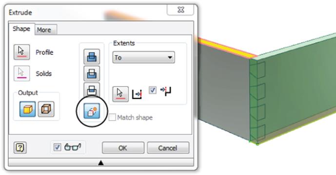
Figure 4.28 A multi-body part
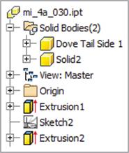
Figure 4.29 Multiple solid bodies in the Solid Bodies folder
You can use the ViewCube to examine the resulting cut. You'll learn more about multi-body parts in Chapter 5, including how to use the Make Components tool to write out each solid body as an individual part file. You can close the file without saving changes.
Creating Revolved Parts
Creating turned and revolved parts is a regular occurrence in many engineering departments because of the types of parts designed and manufactured. The parts consist of circular features around a common axis. There are two different workflows for creating circular parts, each with its own advantages and disadvantages. Creating threads on a part presents another challenge.
You can create circular parts using a single sketch and revolving it around a centerline axis. Alternatively, you can create multiple circular extrusions to produce the same part.
There are also two different workflows for creating threaded features on a part. You can add threaded features to any circular component by means of the Thread feature, which creates cosmetic threads on the part, or through the use of the Coil feature, which creates physical threads. Typically, physical threads are created only when that geometry is required for the model. Generally, using cosmetic threads is sufficient because they are an intelligent feature that can be retrieved in the detail drawing of the part and called out as per the specifications of the feature.
Revolved Cylindrical Parts vs. Stacked Circular Extrusions
Revolved cylindrical parts utilize a sketch with a center axis. Figure 4.30 illustrates two ways to create the same sketch. The view on the left shows a sketch profile anchored at the origin and dimensioned from the origin. The view on the right illustrates the same sketch anchored at the origin but dimensioned from a created centerline, which creates diametric dimensions. The two sketches will create the same revolved feature, the difference being that the centerline allows you to dimension the sketch using diameter dimensions to maintain the design intent of the part.
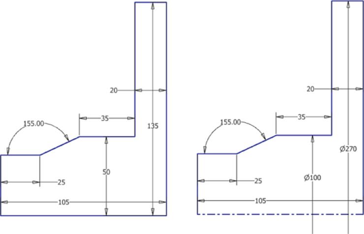
Figure 4.30 Dimension to the sketch vs. centerline
You create the centerline by using the Line tool with the Centerline tool toggled on. In this example, the centerline was created starting at the origin point and continuing to the right of the sketch, extending beyond the sketch for selection ease. When dimensions are created on the sketch and terminated at the centerline object, they will actually extend to the other side of the revolved part diameter.
You could create most revolved shapes by extruding sketched circles as well, but it's often best to use a revolve feature instead. The advantage of creating a revolved profile rather than creating stacked circular extrusions is that the relationship of every portion of the sketch can be easily visualized from the start. The disadvantage is that a contour sketch is not always easily edited to remove or change a portion of the feature. In addition, if the sketch is not fully dimensioned and constrained, it can create errors down the line with faces and edges. For this reason, you should always fully dimension and constrain your sketches. Figure 4.31 shows the same part modeled using both approaches.
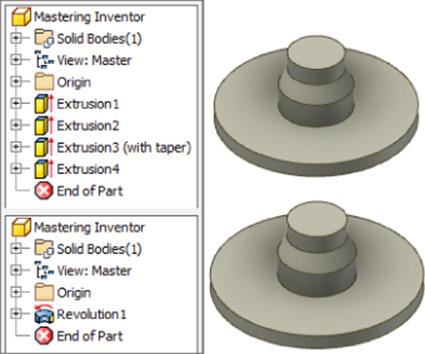
Figure 4.31 Revolved circular feature vs. stacked circular extrusions
Creating Revolved Parts
Revolved features can be used to create parts or features, and they can be created as solids or surfaces. Follow these steps to see how revolves are created:
1. Open the file mi_4a_032.ipt.
2. Select the Revolve button on the 3D Model tab.
3. For the profile, select the rectangular sketch profile and the small circle.
4. Click the Axis button in the Revolve dialog box and then select the line indicated on the part for the axis.
5. Set the operation to Cut so that you are milling out the revolved profile.
6. By default the Extents drop-down is set to Full, giving you a 360-degree revolve. In this part, though, a full revolve cut would cut away a portion of the existing part. So, you will set the Extents drop-down to Angle instead. Notice the other extents options available. They should all look familiar as options from the Extrude tool.
7. Set the angle to 180 and then click the OK button. Figure 4.32 shows the revolve options.
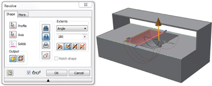
Figure 4.32 Revolving a cut feature
This demonstrates how to create a revolved cut at a specified angle. You can close this file and continue to explore the use of the Revolve tool to create surface features.
Next, you'll use the Revolve tool on an open profile to create a revolved surface. You'll then use a tool called Thicken to turn the surface into a solid.
1. Open the file mi_4a_034.ipt.
2. Before creating the revolve feature, you need to supply the sketch with some missing dimensions. To do so, right-click Sketch1 in the browser and choose Edit Sketch.
3. Place dimensions from the points shown in Figure 4.33 to the centerline, and you'll notice that because the line is a centerline type, the dimensions are automatically diameter dimensions. Before placing the dimension, you can right-click and choose Linear Dimension if a diameter is not the correct choice.
4. Once you've added the dimensions, click the Finish Sketch button and click Revolve on the 3D Model tab.
5. For the profile, select the sketch profile.
6. Click the Axis button and then select the centerline.
7. Because the sketch was an open profile, the Surface output is automatically selected. Click the OK button to create the revolved surface.
8. Next, you'll add some fillets. On the 3D Model tab, click the Fillet button and click the intersecting circular edges on the surface feature.
9. In the Fillet dialog box, change the radius to 12 mm and then click the OK button.
10.In the Modify panel on the 3D Model tab, use the flyout menus to locate the Thicken/Offset tool (look under the Combine button). Once located, click the Thicken/Offset button.
11.Click the Quilt option in the Thicken/Offset dialog box to allow you to select all the surface faces at once and then click anywhere on the surface. Then click the OK button.
12.Rotate the part or use the ViewCube, and you'll see that the surface is still visible. Locate it in the Model browser and then right-click and turn its visibility off. Figure 4.34 shows the revolved shape.
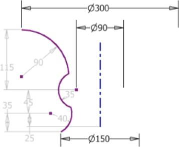
Figure 4.33 Adding dimensions to a centerline
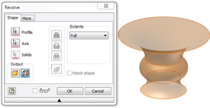
Figure 4.34 A revolved and thickened surface
Creating Work Features
A work feature is construction geometry used when part geometry is not present to create new features. There are three types of work features: work planes, work axes, and work points. In addition to work features that you might create, each part contains origin planes, axes, and an origin point. You can view these by expanding the Origin folder in the Model browser (as shown in Figure 4.35), right-clicking each feature, and selecting Visibility. Note that in Figure 4.35 the 3D indicator arrows have been drawn in for clarity. If it helps you, though, you can turn the indicator on and have it display in the lower left of your screen by selecting the General tab of the Application Options dialog box.
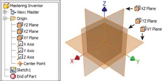
Figure 4.35 Origin work features turned on
Work Planes
A work plane is an infinite construction plane that is parametrically attached to a feature or features, typically to help you define other geometry. Work planes are created based on the geometry you select. Every work plane type is created by defining a location and an orientation. You can use the generic Plane button to create work planes or use the buttons in the Plane drop-down menu. The following brief exercises will demonstrate the creation of each type of work plane.
Midplane Between Two Parallel Planes
To create a plane running midplane between two parallel planes, follow these steps:
1. Open the file mi_4a_040.ipt.
2. Click the Plane button on the Work Features panel.
3. Select the yellow faces on each side of the part, and you will see a work plane placed halfway between them.
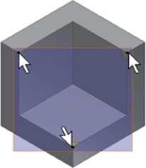
Three Point
To create a three-point work plane, follow these steps:
1. Open the file mi_4a_041.ipt.
2. Click the Plane button on the Work Features panel.
3. Select the corner vertices indicated by the yellow corner faces, and a work plane will be created using these three points.
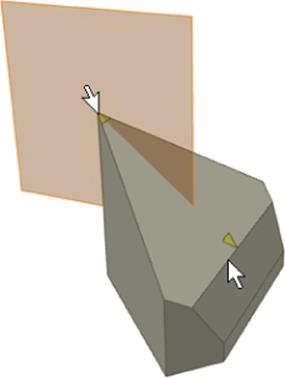
Normal to Axis Through Point
To create a plane that is normal to an axis and running through a point, follow these steps:
1. Open the file mi_4a_042.ipt.
2. Click the Plane button on the Work Features panel.
3. Select the corner vertex indicated by the yellow corner pointer face at the sharp point and the edge indicated by the other, and a work plane will be created using these two points.
Parallel to Plane Through Point
To create a plane running parallel to another plane and running through a point, follow these steps:
1. Open the file mi_4a_043.ipt.
2. Click the Plane button on the Work Features panel.
3. Select the corner vertex indicated by the yellow corner pointer face at the sharp point and the large yellow face, and a work plane will be created using these two points.
Two Coplanar Edges
To create a plane using two coplanar edges, follow these steps:
1. Open the file mi_4a_044.ipt.
2. Click the Plane button on the Work Features panel.
3. Select the edges indicated by the yellow pointer faces, and a work plane will be created using these two edges.
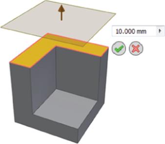
Offset from Plane
To create a plane offset from another plane or face, follow these steps:
1. Open the file mi_4a_045.ipt.
2. Click the Plane button on the Work Features panel.
3. Click the yellow face and drag in the offset direction.
4. Enter the offset distance and click the green check mark to create the plane.
5. Double-click the work plane in the browser to change the offset value.
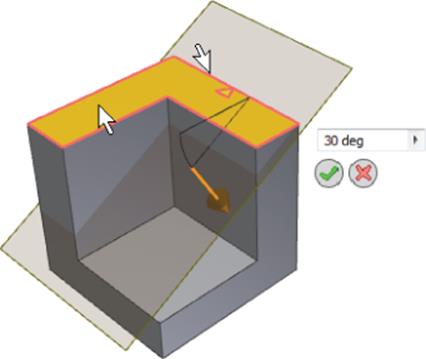
Angle to Face Around Edge
To create a plane on an edge at an angle to a face, follow these steps:
1. Open the file mi_4a_046.ipt.
2. Click the Plane button on the Work Features panel.
3. Select the edge indicated by the yellow pointer face and the yellow face.
4. Enter an angle relative to the selected face and click the green check mark to create the plane.
5. Double-click the work plane in the browser to change the angle value.
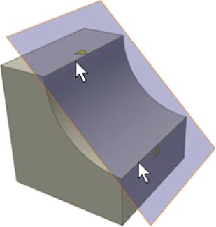
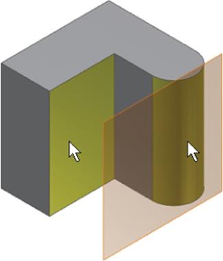
Tangent to Surface and Parallel to Plane
To create a plane tangent to a surface and parallel to another plane, follow these steps:
1. Open the file mi_4a_047.ipt.
2. Click the Plane button on the Work Features panel.
3. Select the yellow curved face and then select the flat yellow face, and a work plane will be created tangent to the curved face and parallel to the flat face.
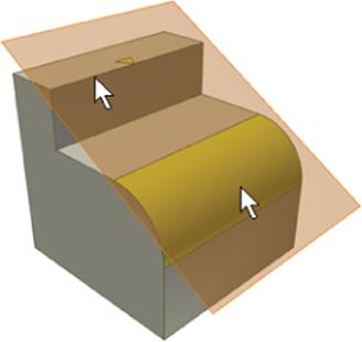
Tangent to Surface Through Edge
To create a plane tangent to a surface running through an edge, follow these steps:
1. Open the file named mi_4a_048.ipt.
2. Click the Plane button on the Work Features panel.
3. Select the yellow curved face and the edge indicated by the yellow pointer face, and a work plane will be created tangent to the curved face and running through the selected edge.
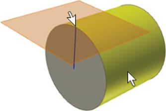
Tangent to Surface Through Point
To create a plane tangent to a surface running through a point, follow these steps:
1. Open the file mi_4a_049.ipt.
2. Click the Plane button on the Work Features panel.
3. Select the yellow, curved face and the endpoint of the sketch line, and a work plane will be created tangent to the curved face at the end of the selected line.
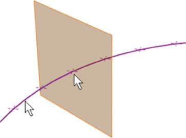
Normal to Curve at Point
To create a plane normal to curve at a point, follow these steps:
1. Open the file mi_4a_050.ipt.
2. Click the Plane button on the Work Features panel.
3. Select any of the sketch points and then select the arc, and a plane will be created at the intersection of the two.
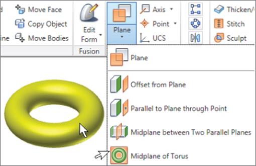
Midplane of a Torus
To create a plane that runs midplane of a torus, follow these steps:
1. Open the file mi_4a_051.ipt.
2. Click the flyout arrow (the small black arrow below the Plane button) on the Work Features panel.
3. Click the Midplane Of Torus button.
4. Select anywhere on the torus, and the plane will be created.
Workplane Tips
Here are some other points to remember about work planes:
· You can right-click a work plane in the browser or the graphics window and then select Show Inputs to see how that work plane was created.
· You can move a work plane by clicking an edge and dragging. This will slide the work plane in the plane of its definition only.
· When you place the mouse pointer on any corner of the work plane, a resize arrow appears, allowing you to drag the corner of the work plane to resize it.
· You can also right-click and set a work plane to autoresize, allowing it to resize off the extents of the part as it changes.
· Work planes have a positive side and a negative side to them. The normal (positive) side has an orange tint, and the non-normal (negative) side has a blue tint. You can right-click a work plane and choose Flip Normal if needed.
· If you do not have the geometry you need present when creating work planes, you can right-click and choose Create Axis or Create Point to create an in-line work feature. In-line features are stacked in the Model browser and automatically set not to display.
· When you start the Work Plane tool, you can right-click and choose Repeat Command to set the work feature tools to stay on until you right-click and choose Done. This helps when you are creating a lot of work features because you do not have to keep clicking the button each time.
Work Axes and Work Points
Much like a work plane, a work axis or work point can be used to create helper geometry in your model. Work points are often created in order to define work planes or work axes. Work axes are often created to help define work planes.
Work Axes
A work axis is a construction line of infinite length that is attached to a part based on the geometry used to create it. You can create a work axis on linear edges through circular faces and edges; through any combination of work points, midpoints, and vertex points; along 2D and 3D sketch lines; and at the intersection of work planes. You can locate several input-specific buttons for creating work axes by clicking the flyout button next to the Axis button, as shown in Figure 4.36.
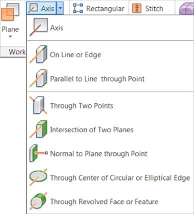
Figure 4.36 Methods for creating work axes
Work Points
Work points can be created at the intersection of planes, surfaces, edges, work axes, 2D or 3D sketch lines, work points, and sketch points, in any combination. They can also be placed directly on sketch points, vertex corners, center points, edge midpoints, or grounded work points. You can locate several input-specific buttons for creating work axes by clicking the flyout button next to the Axis button, as shown in Figure 4.37.
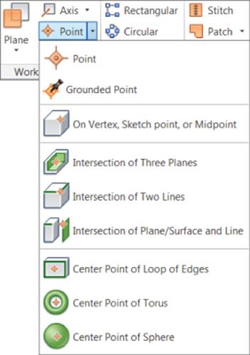
Figure 4.37 Methods for creating work points
Grounded Work Points
Grounded work points are much like regular work points, but they have all of their degrees of freedom removed and are therefore locked to a specific coordinate. To edit a grounded work point, you can right-click it, choose 3D Move/Rotate, and then use the precise input toolbar to make adjustments. You can right-click a regular work point and choose Ground to convert it to a grounded work point.
Renaming Work Features
Taking the time to rename work features can be helpful if you find that you must create and edit a lot of them. However, if you use just one or two here and there, it may not be that helpful. Using a consistent naming scheme will help you easily determine the work feature's use.
Creating Fillets
The Fillet tool in Inventor may seem daunting at first because of the number of buttons and the combination of options, but once you understand the layout of the dialog box and the intended use of the options, you'll be able to create fillets of all types. There are three basic types of fillets:
1. Edge Fillets These are fillets created based on selected edges.
2. Face Fillets These are fillets created between two faces or face sets.
3. Full Round Fillets These are fillets that are tangent to three adjacent faces or face sets.
When you start the Fillet tool (on the Modify panel of the 3D Model tab), it will default to edge fillets. You can switch the fillet type by using the buttons on the left of the dialog box.
Work Feature Visibility vs. Display
Many Inventor users fight the control of visibility of work features (work planes, work axes, and work points) because of a lack of understanding of the tools available to control it. There are basically two methods of preventing work features from displaying on-screen:
· Right-click the work feature and toggle off Visibility. (Always use this at the part level.)
· On the View tab, click Object Visibility and then use one of the options listed. (Do not use this at the part level but only at the assembly level.)
Both methods turn off the display, but only the first toggles the visibility setting for each object. The second is a display override that suppresses the work feature display but does not change the visibility setting.
The difference between the two methods becomes important at the assembly level. If you've used the Object Visibility tool to “override” the work feature visibility setting at the part level, you will find that all of the work features will display when you place the part into an assembly. This requires you to toggle them all off again at the assembly level, and you will be required to do so for each instance of the part placed. You could use the Object Visibility tool in the assembly and suppress the display of all the work features for the entire assembly, but doing so doesn't allow you to access one or two work features at a time. As a result, you end up with all or none of the work features displaying.
To properly control work feature visibility, you should develop the habit of always right-clicking the work features at the part level and explicitly toggling off the visibility setting, and never use the Object Visibility override in a part. If you do this, then when the part is used in an assembly, you can control the work features on an individual basis, per instance of the part. Then you can use the Object Visibility tool to toggle all the visible work features on and off effectively.
Edge Fillets

Edge fillets are the most common type and therefore naturally have the most options. When edge fillet is the active type, you'll see three tabs across the top of the dialog box, allowing you to set the following edge fillet subtypes: constant, variable, and setbacks.
Constant Fillets
Constant fillets have the same radius along the entire length of the edge. On the Constant tab, you can select a group of edges and then set the radius and type. You can create a new size group by clicking the Click To Add row in the selection pane and changing the radius size. Figure 4.38 shows two constant fillet groups being created. In this case, each group contains only one edge, but they vary in radius.
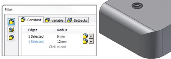
Figure 4.38 Creating two edge fillets of different sizes
Fillet Failures
If you attempt to place multiple fillets at once, you might be alerted to the fact that some of the edges could not be blended successfully using the current radius size, in which case you can choose to place the successful fillets and skip the others.
One of the most common issues with edge fillets arises when you select multiple edges that converge on a single corner vertex. Unfortunately, when this happens, the error message might erroneously indicate an issue with the fillet size. However, you can generally resolve this issue by removing one or more of the competing edges from the selection, applying the fillet feature, and then applying another fillet feature using the previously removed edges. Keep this in mind as you place edge fillets, and remember that just because you can place multiple sizes of edge fillets all in one feature doesn't mean it's always the best solution.
Also on the Constant tab you can change the selection method from Edge to Loop or Feature. Figure 4.39 shows the selection method set to Feature and the results of selecting a hole. Note that all edges created by the hole feature are selected.
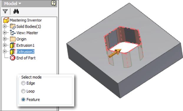
Figure 4.39 Fillet selection by feature
You can also select All Fillets (inside corners) or All Rounds (outside corners) to apply fillets to a part quickly, where it makes sense to do so. Figure 4.40 shows the same part with all fillets applied on the left and all rounds applied on the right. Keep in mind that you can select all rounds and fillets at once as well.
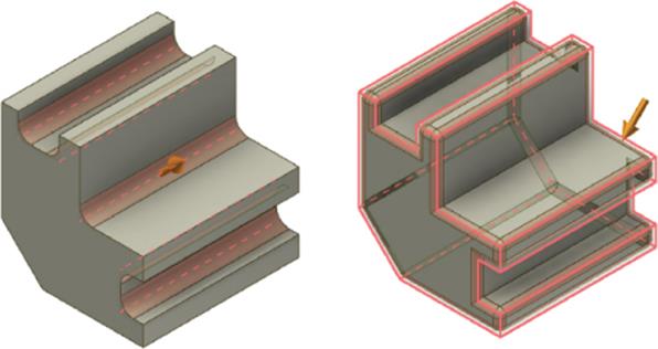
Figure 4.40 All fillets vs. all rounds
Variable Fillets
In contrast to constant-edge fillets are variable-edge fillets. Variable-edge fillets can have multiple radius sizes along the length of the edge. To create variable fillets, click the Variable tab and then select an edge to make it variable. By default, the start points and endpoints are added to the right pane. You can add points by simply clicking the edge in the place or places you want to transition to a different radius.
Once points are selected, you can change the radius and position of each point. The number listed in the Position column is a decimal percent of the edge length rather than the length. For instance, Figure 4.41 shows a point has been added at 0.5 ul or 50 percent of the edge length coming off the start end. Recall that ul is simply Inventor's abbreviation for unitless, which is automatically applied to parameters that do not require a unit suffix.
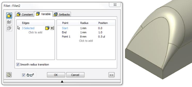
Figure 4.41 A variable-edge fillet
Setbacks
Setbacks define the corner where multiple-edge fillets come together. Once you select edges in the Constant tab, you can switch to the Setbacks tab and select corners to apply setbacks to. Setbacks are typically used for cast and molded parts where the corners cannot be too sharp.
On the Setbacks tab, select a corner using the Vertex pane first. Then enter a setback distance for each edge. Setback values should be no longer than the length of the edge they are placed on. You will typically get an error if you attempt to specify a value that is larger. If you click the Minimal check box, the setbacks will automatically adjust to the smallest length that can be built. Figure 4.42 shows a setback being created, along with the result.
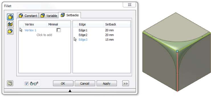
Figure 4.42 A setback fillet
Face Fillets
Face fillets are added between two selected face sets. These faces or sets of faces do not need to share a common edge. You can adjust the radius once the fillet is previewed, but typically if you do not get a preview, it indicates an invalid selection set. You can add more faces, or you may need to use a different type of fillet solution.
Two options are selected by default:
1. Include Tangent Faces Use this option to allow the fillet to continue over tangent, adjacent faces. Deselect this option to ensure that the fillet is only between selected faces.
2. Optimize For Single Selection Deselect this option when making multiple selections per face set. When this option is selected, the selection automatically changes from selection set 1 to selection set 2.
Figure 4.43 shows a face fillet created between the two dark faces.
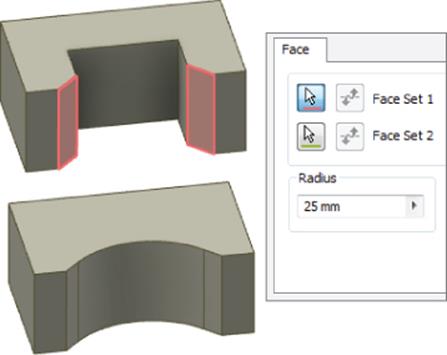
Figure 4.43 Creating a face fillet
Full Round Fillets
Full round fillets can be used to quickly round over a feature without having to know the radius that would complete the full round. You can also use this option to create a full round on faces that are not parallel. To create this type of fillet, simply select the faces in the order in which they occur from side to center to other side, and the center face will be replaced with the radius face.Figure 4.44 shows a full round. The selection options are the same as described previously for the face fillet.
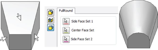
Figure 4.44 A full round fillet
Working with Fillet Features
In this section you'll create the various types of fillets discussed in the previous pages. To begin, open the file mi_4a_053.ipt. Then follow these steps:
1. Select the Fillet tool on the Modify panel of the 3D Model tab (or press F on the keyboard).
2. You'll create a simple edge fillet. Select the vertical edge where the yellow and blue faces intersect.
3. Set the fillet radius to 18 mm and click the Apply button.
4. Next, you'll create a variable fillet. Click the Variable tab in the Fillet dialog box.
5. Select the edge where the purple and red faces intersect.
6. Set the radius for the start and endpoints to 2 mm.
7. If needed, click the word Start to set the dialog box from edit mode back to selection mode and then click anywhere on the edge between the purple and red faces.
8. Change the radius to 6 mm and then set the position to 0.5 to set the new variable point to be halfway between the start and endpoints. Note that you could add additional variable points to further define the variation of the fillet. In this case, though, just click the Apply button to create the variable fillet.
9. Next you'll create a fillet setback. To do so, switch back to the Constant tab and set the radius to 2 mm.
10.If needed, click the Pencil icon in the current row to set it from edit mode to selection mode.
11.Select the edge between the yellow and pink faces and then the edge between the yellow and green faces. It may help to zoom in on the corner.
12.In the Fillet dialog box, click the Click To Add text to add another row to the list.
13.Change the radius to 3 mm and then click the Pencil icon to set the row back to selection mode, if needed.
14.Select the edge between the pink and green faces.
15.Select the Setbacks tab in the Fillet dialog box.
16.Choose the corner where the yellow, pink, and green faces intersect. You should see the vertex highlight as you locate it.
17.Enter 6 mm for all of the setback values and then click the Apply button to create the fillets with setback.
18.Next, you'll create a face fillet. Click the Face Fillet button on the left of the Fillet dialog box (the one in the middle).
19.For Face Set 1, choose one of the orange faces; for Face Set 2, choose the other. Then click the Apply button.
20.And finally, you will create a full round fillet. Click the Full Round Fillet button on the left of the Fillet dialog box.
21.Select the tan faces on the protruding front feature in consecutive order (the right face for Side Face Set 1, the top face for Center Face Set, and the left face for Side Face Set 2, for example).
22.Click the OK button to create the fillet and close the Fillet dialog box.
Take a look at the fillet features in the browser tree. You can right-click any of them and choose Edit Feature to adjust the fillet as needed. To add edges to or remove edges from any given fillet feature, you can use the Ctrl key and then click the edges on-screen.Figure 4.45 shows the part before and after fillets were applied. You can close the file without saving changes.
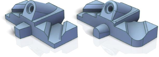
Figure 4.45 Before and after fillets
Note that if you try to place a fillet along the edges where the pink and red faces intersect, you will receive an error because of the way the resulting fillet tapers. However, if you also choose the corresponding edges on the opposite of the rounded feature, the fillet will build without problems. Keep this in mind as you work with fillets that form sharp tapers.
Color Overrides
To change the color of any individual face on a model, you can right-click the face and choose Properties from the context menu. You can do the same for entire features by right-clicking them in the browser and choosing Properties.
To remove color overrides for entire solids, you can expand the Solid Bodies folder in the browser, right-click a solid, and choose Properties. In the Body Properties dialog box, you can set Body Appearance to As Part, select the Clear All Overrides check box, and then click the OK button. Be aware that parts translated from other file formats often come in with many color overrides and the Clear All Overrides action can take a while to process.
Creating Threaded Features
Inventor offers the option of creating cosmetic threads that represent actual threads in the part, and it creates 2D geometry information for detailing those threads. Cosmetic threads are created with a threaded hole feature. Or you can use the Thread tool on the Feature panel bar to add threads to existing part features. The thread features are added to the Model browser as separate features.
Creating Cosmetic Threads Using the Thread Tool
Creating cosmetic threads on a circular part is a relatively simple procedure. Cosmetic threads work by wrapping a scaled graphic around the feature to represent threads. This allows the model file size to stay smaller because it is not required to calculate all of the extra edges and faces of the threads. However, the cosmetic Thread tool does create fully intelligent thread features based on the specifications you choose, allowing you to detail the threads quickly and accurately in the drawing environment.
In the following steps, you will use the Split tool to divide a cylindrical surface into multiple faces and then apply cosmetic threads to them:
1. Open the file mi_4a_056.ipt.
2. On the 3D Model tab find the Modify panel and then look for the Split tool in the flyout menus (look under the Combine or Thicken/Offset button). Once you've found it, click the Split button.
3. Select Work Plane1 for the Split tool, select the face of the cylinder it runs through, and then click the OK button.
4. Right-click the edge of Work Plane1 and choose Visibility to turn the plane off. Recall that work planes are selectable only by their edges.
5. Now that the part is divided into two faces, look for the Thread tool in the flyout menus (look under the Shell or Draft button). Once found, click the Thread button and select the shortest face.
6. Click the Specification tab, set Size to 17 and Designation to M17x1, and then click the Apply button.
7. Switch back to the Location tab and click the end of the middle cylinder.
8. Uncheck the Full Length check box and enter 5 mm for the Offset and 30 mm for the Length. Click the direction button if you do not see the threads appear. Click the Apply button.
9. Run your mouse pointer over the third cylinder, and notice that as you get closer to one end or the other, the offset and direction switch.
10.Click the face and apply another set of threads of any type you like; when you've finished, click the OK button. Figure 4.46 shows the Thread tool options.
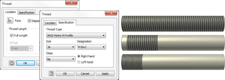
Figure 4.46 Placing cosmetic threads
3 D Threads from Your Cosmetic Threads
Unless you are going to actually cut threads directly from your 3D model, cosmetic threads are usually sufficient. The advantage of these threads is that they contain all the thread information in the model that can later be extracted in a drawing without carrying the burden of complex modeling features.
Inventor pulls its thread specification information from the Thread.xls file found in the Design Data folder. You can edit this file to contain custom thread specifications and include proprietary threads or industry-specific threads not commonly listed.
If you find that you do need to generate 3D threads from your cosmetic threads, maybe for a 3D printed part, for example, you can download the ThreadModeler tool from the Autodesk Exchange Apps website: http://apps.exchange.autodesk.com.
Using the Coil Tool to Create Physical Threads
In addition to using the ThreadModeler add-in tool found at the http://apps.exchange.autodesk.com website, you can create physical threads using the Coil tool. Physical threads create large file sizes compared to cosmetic threads and can seriously affect performance and assemblies. As a result, physical threads should be used only where absolutely necessary, such as in the design of a bottle or jar top or other geometries such as a worm gear. You can explore the creation of a physical thread with the Coil tool in these steps:
1. Open the file mi_4a_057.ipt.
2. In the Model browser, select the sketch called Thread Cut Sketch, right-click, and select Edit Sketch.
3. Right-click and choose Slice Graphics (or press F7 on the keyboard) to temporarily slice away the material that hinders your view of the sketch. Recall that this option is available only while creating or editing a sketch that runs through a solid.
4. Zoom in on the sketch, change the depth dimension to 2 mm, and then click the Finish Sketch button to exit the sketch.
5. Zoom out (or double-click the mouse wheel to zoom all) and then locate and click the Coil tool in the flyout menu found on the Create panel (look under the Sweep button).
6. Select the sketch profile if it does not automatically select and then select the work axis in the center of the cylinder for the axis.
7. Use a direction button to make sure the coil is running the correct way and then click the Cut button.
8. Click the Coil Size tab, change the pitch to 4 mm and the revolution to 12, and then click the OK button.
Figure 4.47 shows the Coil Size tab. Be aware that you can create coils by specifying pitch and revolution, revolution and height, and pitch and height, or by defining a spiral. Also note the suffix of ul shown in the Revolution drop-down box. This suffix just means that the value is unitless. You do not have to specify this because Inventor will do so as needed.
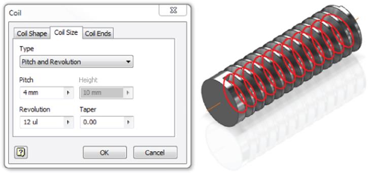
Figure 4.47 Creating a physical thread with the Coil tool
Hole Features
Using Inventor's Hole tool, you can create counterbore, countersink, spotface, and drilled holes with user-defined variables such as thread designation and drill point angle. You can also specify a simple hole, a tapped hole, a tapped tapering hole, or a clearance hole.
Using the Thread and Clearance Spreadsheets
Two external files are related to the Hole tool: Thread.xls and Clearance.xls. Both files load at the time of installation to a Design Data folder in the install directory location, such as C:\Users\Public\Documents\Autodesk\Inventor 2015\Design Da-ta\XLS\en-US. If the Design Data folder has been relocated, you can determine its location by following these steps:
1. On the Get Started tab, click Projects.
2. In the Projects dialog box, ensure that you are looking at the correct project and locate and expand the Folder Options node in the lower pane.
3. Note the Design Data path listed.
4. If the Design Data path says = Default, then your project is reading the path from Inventor's options, so you should select the Tools tab, click Application Options, and select the File tab in the dialog box that opens. Note the Design Data path listed.
Once the path is determined, you can browse to the path and find the thread and clearance spreadsheets and make customizations as follows. To edit the thread spreadsheet, follow these steps:
1. Close Inventor.
2. Make a copy of the original spreadsheet and store it in a safe location (this is just a precaution).
3. Open the Thread.xls file in Microsoft Excel.
4. To add or modify custom thread designations for an existing thread type, do the following:
a. Choose the worksheet you want to customize.
b. Edit the values in the Custom Thread Designation column to include your designations. These will then be available in the Thread and Hole tools and can be recovered in hole notes in a drawing.
c. Edit cell B1 to change the name Inventor displays in the Hole and Thread tools.
d. Edit cell D1 to change the order in which Inventor lists the thread types in the Hole and Thread tool dialog boxes.
5. To add a new thread type, complete these tasks:
a. Copy an existing worksheet of the same type (parallel or taper).
b. Rename the custom worksheet as required.
c. Delete most or all of the rows below row 3. You may want to keep at least one row to use as a reference, at least temporarily.
d. d. Add rows as required.
e. Edit cell B1 to change the name Inventor displays in the Hole and Thread tools.
f. Edit cell D1 to change the order in which Inventor lists the thread types in the Hole and Thread dialog boxes.
g. Hover your mouse pointer over cell A1 to see the tool tip containing the letter designations and mark your sheet as appropriate.
6. Save the spreadsheet.
7. Restart Inventor. Changes are read when Inventor loads.
The process to modify Clearance.xls is similar.
Creating Holes in Parts
You have four options for placing holes with the Hole tool:
· From Sketch
· Linear
· Concentric
· On Point
To explore these placement options, open the file mi_4a_055.ipt from the Chapter 4 folder of your Mastering Inventor 2015 directory, and follow these steps:
1. Select the Hole tool on the 3D Model tab (or press H on the keyboard).
2. You'll notice that the Placement option is set to From Sketch. This is because Inventor has detected that there are two sketches available for use. Click Cancel to exit the Hole tool.
3. Right-click Sketch5 in the Model browser and choose Visibility to turn the visibility of this sketch off.
4. Start the Hole tool again. This time Inventor detects that there is only one sketch available and automatically selects the center point found in that sketch.
5. Click the counterbore option, set the counterbore (as shown in Figure 4.48), and then click the OK button.
6. Right-click Sketch5, turn the visibility back on, and then click the Hole button again. Notice that it selects the center points automatically again. This is helpful; however, you do not want the hole in the hex-shaped cutout to be the same size as the others in this sketch. Hold down the Ctrl key and click the center point at that location to remove it from the selection.
7. Choose the spotface option, and notice that it is essentially the same as the counterbore with the exception of the depth measurement. In the spotface, the depth is measured from the bottom of the bore. Set the spotface as shown in Figure 4.49 and click the OK button.
8. Since you removed the one center point before placing the spotface holes, you will reuse that sketch to place the next hole. To do so, that sketch must be visible. The Hole tool has toggled the visibility back off, so you need to locate Sketch5 again and make it visible.
9. Place a simple drilled hole using the center point in the hex-shaped cutout. Set the termination to Through All and the diameter to 9 mm, and click the OK button. Then turn the visibility of the sketch off one last time.
10.Start the Hole tool again. You'll note that because there are no longer any visible sketches, the From Sketch option is no longer the default placement option. Set the placement to Concentric and select the top face of the part for the Plane input.
11.Next, you need to specify a concentric reference. Select one of the yellow faces (or the circular edge of the yellow face).
12.Set the hole to the countersink option and then set the inputs as shown in Figure 4.50. Click the Apply button (not the OK button just yet).
13.Set the plane, use the other yellow face to place another countersink of the same size, and then click the OK button.
14.Change your view so that you can see the work point at the work axis intersection of the green face.
15.Start the Hole tool again and set the placement option to On Point.
16.Select the work point for the point input and then the work axis for the direction. Flip the direction if needed, using the button next to the Termination drop-down.
17.Leave the hole at the simple drilled option and set the Termination drop-down to To.
18.For the To selection, click the bore face of the counterbore hole and click the Terminate Feature check box.
19.Click the clearance hole option, set the options as shown in Figure 4.51, and click theOK button.
20.Rotate the part so that you can see the underside and zoom in on the feature with the red face.
21.Start the Hole tool again and select the red face for the Face input.
22.Select one of the longer straight edges for Reference1 and set the dimension to 8 mm. Select one of the shorter edges and set the dimension to 12 mm.
23.Set the termination to Through All and the hole type to Taper Tapped Hole.
24.Choose Din Taper from the Thread Type list, set the size to M5, and then click the OK button. You'll note that the hole is cut with the appropriate taper.
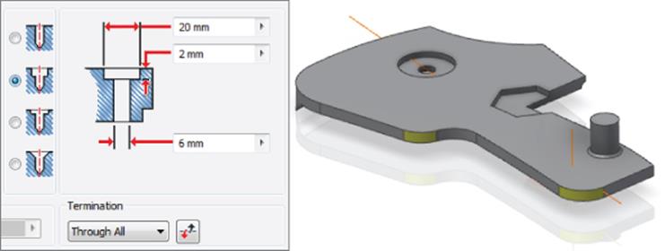
Figure 4.48 Counterbore settings
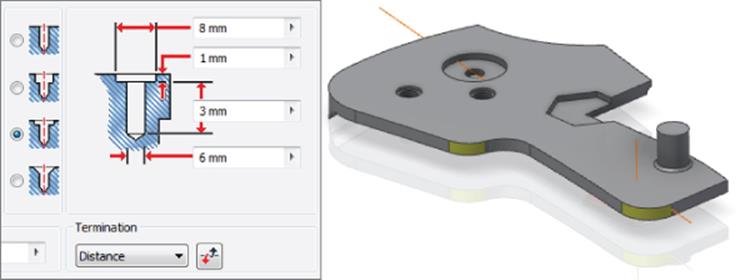
Figure 4.49 Spotface settings
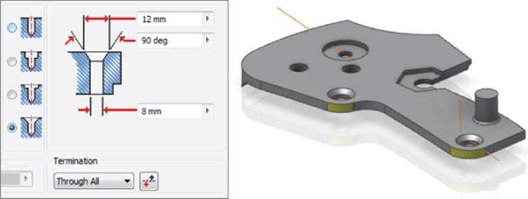
Figure 4.50 Countersink settings
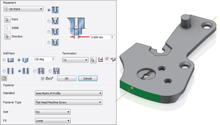
Figure 4.51 Clearance hole settings
You can close the part without saving changes when you have created all the holes.
As you can see, the Hole tool has an abundance of options allowing you to specify holes in a variety of ways. Keep in mind that features created with the Hole tool carry more intelligence with them than a simple circular extrude cut. This is particularly true when you begin to detail a part in the drawing environment.
Setting Tolerance Values in Holes
You can set tolerances for hole dimensions in the Hole dialog box. When setting a hole dimension, right-click a dimension edit box and then select Tolerance, as shown in Figure 4.52.
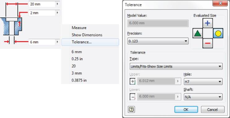
Figure 4.52 Tolerance settings
You can use these general steps to access the tolerance settings:
1. In the Tolerance dialog box, change the values as desired:
· In Precision, click the arrow to set the decimal precision of the dimension.
· In Evaluated Size, select Upper, Nominal, Median, or Lower to use when evaluating the dimension. This will set the size at which the hole is actually created.
· In Type, click the arrow and select a tolerance type for the selected dimension.
2. Depending on your selection, enter values to set the upper and lower tolerance range and the tolerance for the hole and shaft dimensions (for Limits and Fits).
3. Click the OK button.
This will return you to the Hole dialog box. Keep in mind that although the value in the hole input will not change, the hole will be drawn to the tolerance you selected in the model. For instance, if the Upper option were selected in the hole shown in Figure 4.52, the hole would measure 6.012 mm rather than 6.000 mm. You'll learn more about using tolerances in Chapter 5.
Bend Parts
You can use the Bend Part tool to bend a part based on a sketched bend line. You can specify the end of the part to bend, the direction of the bend, the angle, the radius, and the arc length. You can find the Bend Part tool on the Modify tab of the 3D Model tab. By default, it is hidden from view and must be accessed by using the flyout (the small black triangle on the Modify panel).
Here are some guidelines to be aware of when using the Bend Part tool:
· Sketches used for bend lines must be visible and unadaptive and should be located on a plane or surface that contacts the part.
· A sketched line on the top face of a part does not allow for the part to be bent down, only up, whereas a sketch that runs through the part allows the bend to be built up or down.
· Bend Part does not account for bend allowances in the way sheet-metal features do and therefore should not be used with sheet-metal parts.
· You can specify the bend by Radius & Angle, Radius & Arc Length, or Arc Length & Angle.
Follow these steps to create a simple bend part:
1. Open the file named mi_4a_058.ipt.
2. Select the Bend Part tool from the flyout of the Modify panel.
3. Select one of the sketch lines as the bend line.
4. Adjust the arrow buttons so that just the end is bent up. Notice that if you try to bend the end down, it will not work. This is because of the position of the sketch.
5. Set the radius to 100 mm and then click the OK button.
6. The bend will consume your sketch, so you will need to expand the Bend feature in the Model browser and then right-click the sketch and choose Share Sketch.
7. Create another bend to your specifications, experimenting with the other solutions.
Figure 4.53 shows the Bend Part tool in action. You can close the file without saving changes when finished.
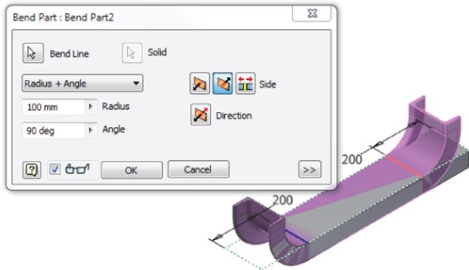
Figure 4.53 Bending a steel shape
Part Modeling Exercise
In the pages that follow, you will create a part similar to the part shown in Figure 4.54. You'll employ some of the tools covered in this chapter and preview some that are covered inChapter 5.
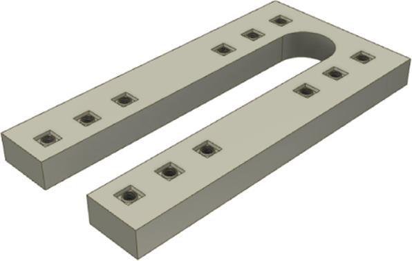
Figure 4.54 The part you'll create in this exercise
Creating a Base Feature
You'll begin by creating a new part file from the Standard(mm).ipt template:
1. On the Get Started tab, click the New button.
2. On the Metric tab of the New File dialog box, select the Standard(mm).ipt template.
3. On the Sketch tab, locate the rectangle drop-down menu (the small black arrow next to the Rectangle button) and click the Rectangle Two Point Center tool.
Projecting the Origin Point
If you do not see an origin point in your sketch, you may want to take this opportunity to turn on the option that will automatically project it into every new sketch. To do so, just follow these steps:
1. 1. On the Tools tab, click Application Options.
2. 2. Choose the Sketch tab.
3. 3. Ensure that the Autoproject Part Origin On Sketch Create option is selected and click the OK button.
4. 4. Start a new file from a template, and you will see that the origin point is now present.
4. Place the rectangle on the projected origin point.
5. Use the Dimension tool found on the Sketch tab to dimension the sketch at 150 mm by 300 mm, as shown in Figure 4.55.
6. Right-click and choose Finish 2D Sketch; then click the Extrude button on the 3D Model tab.
7. If needed, click the corner of the ViewCube to find an isometric view of the sketch so you can see the preview (if it's not displayed, select the View tab, select the Windows panel, click the User Interface button, and click the drop-down arrow).
8. Generally, Inventor will select the profile for you if you have just one closed profile present to extrude. If the profile is not selected, click anywhere in the rectangle to select it. If you did not make the diagonal a construction line, you will need to select both triangular halves of the rectangle.
9. Enter 25 mm in the Distance input box. Click the arrow buttons to change the extrude direction just to see how the preview updates. Then click the left arrow button and click the OK button.
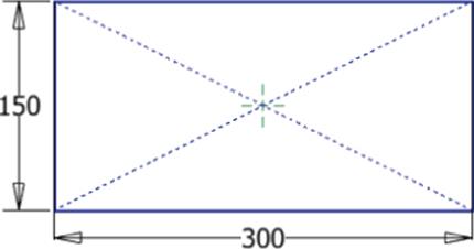
Figure 4.55 Initial sketch
Creating a Second Feature
Now that you've created your base feature, you will continue by adding features to it. Before doing so, it is a good idea to save your part. Click the Save icon from the Quick Access bar at the top of the screen, or click the Inventor button and then select Save. You can save the file in the Chapter 4 folder and name it anything you like.
Now that the part is saved, it's time to create a second feature:
1. On the 3D Model tab, click the Start 2D Sketch button and then click the large front face of the part (or right-click the face and select New Sketch). Sketch2 is now created and active.
2. Use the ViewCube to orient your view of the part so that you have a flat 2D view of your sketch plane with the rectangle running horizontally on your screen.
3. If you see sketch lines outlining the base feature, then you have the Autoproject Edges For Sketch Creation And Edit option turned on. If you do not see those sketch lines, select the Project Geometry tool on the Sketch tab and select the face again to project the edges.
Enabling Project Edges on Sketch Creation
If you see the outline of the faces automatically projected into your new sketches, you may want to consider turning it off. In general, I do not recommend you use this. It may be helpful in the beginning, but be aware that your sketches can become cluttered with unneeded geometry. When all edges are projected, it is more difficult to determine the design intent and edit sketches. Instead, consider disabling this option and developing a practice of projecting only necessary edges.
To do so, follow these steps:
1. 1. On the Tools tab, click Application Options.
2. 2. Choose the Sketch tab.
3. 3. Ensure that the Autoproject Edges For Sketch Creation And Edit option is selected to enable it or deselected to disable it and click the OK button.
4. Sketch a rectangle on the face selected for the sketch. Place this rectangle in the middle of the face, being careful not to accidentally constrain it to the origin point or the edge of the base feature (you will relocate it using a sketch constraint later).
5. Select the Circle tool on the Sketch tab; then sketch a circle at the end of the rectangle starting with the midpoint of the vertical line on the right and snapping to the endpoint of the top or bottom line. You don't need to trim the circle before converting this sketch into a feature, and in fact, unneeded trimming of sketch entities often works against you because it may remove sketch constraints.
6. Use the Dimension tool on the Sketch tab and add a dimension to the circle. Rather than just entering a value, enter Diameter = 40 mm, thereby assigning the dimension a name and a value (be sure you have named this dimension because you will be using it in the steps to come).
7. You'll next create an equation for the length of the rectangle based on the length of the diameter value. With the Dimension tool, select the edge of the rectangle and enter Slot_Length =.
8. Click the 40 mm diameter dimension you just created. This will link the two dimensions. Finish the equation with *5 so that your end equation reads Slot_Length = Diameter*5. Note that you must use an underscore here because spaces are not allowed in parameter names. Your sketch should look similar to Figure 4.56.
9. Create a Coincident constraint between the midpoint of the left vertical line of the rectangle and the midpoint of the left, projected, vertical line of the base feature.
10.Select one (or all) of the projected lines of the base feature and convert it to a construction line (this ensures that Inventor will not attempt to extrude the large projected profile in the next step).
Use Work Features to Anchor Your Sketches
Another way to anchor this sketch to the midplane of the rectangle is by using work features. Before starting a sketch, click the Plane icon on the Work Features panel. Select one side of the rectangular feature and then the other. This will create a parametrically centered work plane.
Then you can create a sketch, and in that sketch use the Project Geometry tool to project the edge of the work plane. This will project the work plane as a line onto the sketch plane. You can then use this line as a centerline in your sketch-creation sequence. If you were to ever change the size of the base feature, then the work plane, and the projected line, this sketch would all update and remain centered.
11.Finish the sketch and choose Extrude on the 3D Model tab.
12.If needed, use the ViewCube to view the part from an isometric view.
13.Select the rectangle and the circle you just created for the profile.
14.Click the Cut button (the second button down in the list of operation buttons) so that the profiles will be cut out of the base feature. Your preview should be red when the Cut operation is selected. Check the direction arrow to ensure that the cut is going in the correct direction.
15.In the Extents drop-down, select All. The All option extrudes the profile through all the current features of the entire part in the specified direction or in both directions if you chose the Midplane option. If the size of the base part features change, the cut extrusion feature will update accordingly. Click the OK button when your options look like Figure 4.57 and then save your file.
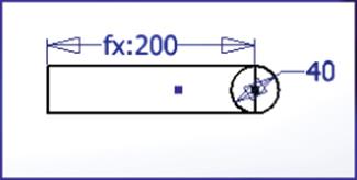
Figure 4.56 Creating and dimensioning geometry in Sketch2
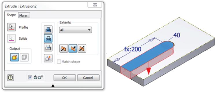
Figure 4.57 Extruding (cutting) the second feature
Creating a Sketch-Based Hole Feature
Hole features are powerful components of Inventor. Many methods are available for creating holes. You can create holes in the following ways:
· By utilizing existing sketches containing sketch center points
· By distance from two planar edges
· On a face by referencing a concentric edge or concentric face
· By using a work point feature
You can continue with the file you are working on or open the file mi_4a_060.ipt. Follow these steps to create another sketch and then use that sketch to place a hole:
1. On the 3D Model tab, click the Start 2D Sketch button and then click the large front face of the part (or right-click the face and select New Sketch). Sketch3 is now created and active.
2. If needed, use the ViewCube to orient your view of the part so that you have a flat 2D view of your sketch plane with the rectangle running horizontally on your screen.
3. You might see the outline of the sketch plane face automatically projected into your sketch (if not, click the Project Geometry button and select the sketch plane).
4. On the Sketch tab, select the Offset button on the Modify panel.
5. Before selecting anything to offset, right-click and ensure that both the Loop-Select and Constrain Offset options are selected.
Loop-Select This option selects lines/curves joined at their endpoints. Deselect to select one or more lines/curves individually.
Constrain Offset This option constrains the distance between the new geometry and the original to be equidistant.
6. Click the radius and then drag the offset profile so that it is created to the inside of the part. Then right-click and click Cancel.
7. Place a dimension between the offset profile and the outside edge of the part and enter Offset = 20 mm in the input box (again, be sure to name this, because you will be using it in the steps that follow).
8. Window-select the entire part/sketch so that all of the lines are selected; then click the Construction button and convert the lines to construction lines.
Select Objects with a Window Selection
You can create multiple entity selections using what is referred to as a window selection. Window selection sets include objects differently depending on whether the window is created from left to right or right to left:
· Position the pointer slightly above and to the left of the leftmost entity to select and then click and drag the pointer slightly below and to the right of the rightmost entity you want to select. All objects that are fully enclosed within the rectangle are selected and highlighted.
· Position the pointer slightly below and to the right of the rightmost entity to select; then click and drag the pointer slightly above and to the left of the leftmost entity you want to select. All objects that are enclosed by and/or intersected by the rectangle are selected and highlighted.
You can use the Ctrl and Shift keys to add entities to and remove entitles from the selection sets.
9. Select the Point tool on the Draw panel of the Sketch tab and place a point on the corner of the offset loop, as shown in Figure 4.58.
10.Finish the sketch and choose the Hole tool on the 3D Model tab.
11.If needed, use the ViewCube to view the part from an isometric view.
12.The Hole tool should have automatically selected your sketch point; if not, make sure the Placement drop-down is set to From Sketch and the Centers button is selected and then select the sketch point on-screen.
13.In the Termination drop-down, select Through All to ensure that the hole depth always cuts through the part. Then set Type to Tapped, set the Threads options to ISO Metric Profile, set Size to 10, and set Designation to M10x1.5 (as shown in Figure 4.59). Click the OK button and save your part.
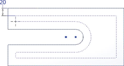
Figure 4.58 Placing a sketch point for hole placement
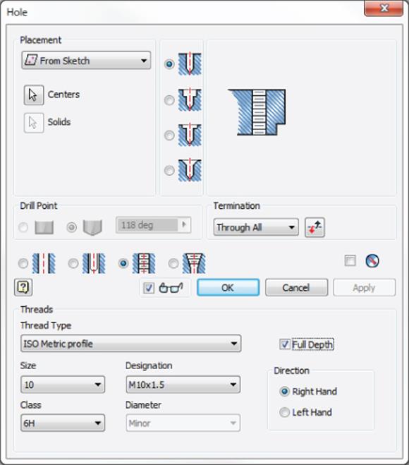
Figure 4.59 Hole options
Selecting Sketched Hole Centers
The Hole tool will automatically select sketched center points as long as only one visible unconsumed sketch is available. If you find that the Hole tool is not picking up your center point automatically, check to see that you haven't accidentally created an extra sketch in the model tree. You can hover your mouse pointer over the Sketch node in the browser to see the sketched entities highlight on the screen. If you determine that you have accidentally created an extra sketch, you can right-click it and click Delete.
Note, too, that only center points (small cross marks) are automatically selected by the Hole tool and simple points are not. However, you can manually select simple points for hole placement. You can also convert center points to simple points, or vice versa, by using the Center Point button on the Sketch tab (you'll find it next to the Construction tool).
Creating a Rectangular Hole Pattern
So far, the features you've created have been based on a sketch. These types of features are, therefore, referred to as sketched features. Features not based on sketches are referred to as placed features. Placed features are solely dependent on existing part geometry. In the pages to come you will explore the steps necessary to create a placed feature in the form of a rectangular pattern.
When creating patterns, you have the choice of creating them at the feature level or at the sketch level. For instance, you could have patterned the sketch point using a sketch pattern and then placed multiple holes at once using the Hole tool. It is generally best, though, to create patterns as features rather than sketch patterns. Here are two reasons to consider feature patterns:
· A feature pattern saves time when creating spaced, multiple instances of a feature, and it makes editing the spacing easily accessible.
· Using a feature pattern in a part allows you to later use that pattern to create a component pattern in an assembly and follow the original part pattern. For instance, if you placed this part into an assembly, you could pattern a bolt to occupy every hole within the pattern by simply constraining one bolt into the original hole feature and then use the Component Pattern tool to automatically pick up the hole pattern count and spacing. The Component Pattern tool is available only within the assembly environment.
First you'll need to determine the pattern spacing. From the creation of the second feature, you know the round end of the slot has a width of 40 mm. From the creation of the placed hole, you know the offset from the slot edge is 20 mm. From this information, you can determine that the spacing of the two rows of holes is (2 × offset value) + 40 mm, therefore 80 mm. Assume the design specification requires eight holes in each row and they need to be spaced at a distance of 25 mm apart. With this information, you are now ready to proceed with creating the hole pattern. You can continue with the file from the previous section or open the file mi_4a_061.ipt. Then follow these steps:
1. On the 3D Model tab, click the Rectangular Pattern button on the Pattern panel.
2. In the Rectangular Pattern dialog box, you are being asked to select the features to pattern. You can select the hole from the graphics area, but you may find it easier to do so from the Model browser. No matter what method you use, check the Model browser to ensure that only Hole1 is highlighted (you can use Ctrl+click to deselect any accidentally selected features).
3. Click the arrow button under Direction 1 and select the edge of the slot cutout. Use a direction button to change the direction, if required, and set the count and spacing to 8 and 25 mm, respectively. You can confirm that your settings look similar to Figure 4.60.
4. Click the arrow button under Direction 2 and select one of the short ends of the part. Use a direction button to change the direction, if required, and set the count to 2.
Although you could just change the spacing value to 80 mm and complete the pattern, you might want to consider what would happen if the width of the slot feature were to change. If that were to happen, the hole pattern spacing would stay at 80 mm and no longer remain symmetric to the slot width. To avoid this, you will make the pattern spacing parametric by calling the dimensions of earlier features into your pattern spacing. In this way, you are building a formula right into the pattern so that if those dimensions change, the spacing setting will follow.
5. To do this, first clear the Direction 2 length input box.
6. Click the arrow at the right of the length input box and click List Parameters from the flyout shown in Figure 4.60.
7. Choose Diameter from the list; then choose List Parameters again and, finally, choose Offset.
8. Edit the input to read Diameter + 2* Offset.
9. If the text shows in red, there is an error. When you have a valid formula, it will display in black. Check the preview, ensure that the pattern looks correct, and then click the OK button. Confirm that your part looks like Figure 4.61 and then you can save your file.
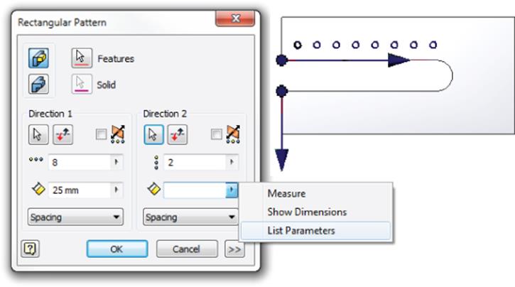
Figure 4.60 List parameters in the Rectangular Pattern dialog box
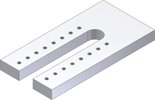
Figure 4.61 A rectangular hole pattern
Editing Sketches and Features
You will often need to modify a sketch and/or feature after you have created it. Oftentimes you may find that because designs are similar, it is most efficient to copy an existing part and then make changes to the copy.
In the next steps, you'll edit some of the features you've just created, but before doing so, it will be helpful to understand the behaviors associated with the model tree and browser nodes. When a feature is sketch-based, you can expand the plus sign next to it to reveal the sketch. Likewise, when a feature has multiple elements such as a pattern, you can expand it to view and control each element. If a feature is placed rather than sketch-based, it may not have any elements and, therefore, will lack a plus sign. Figure 4.62 shows the anatomy of the three browser nodes.
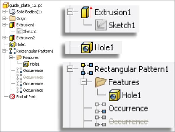
Figure 4.62 Editing features and sketches
The extrusion is based on Sketch1, as you can see. However, the hole in Figure 4.62 is a placed feature based solely on the edges of other features and, therefore, contains no sketch (you'll place a hole of this type in the pages to come). The pattern, when expanded, shows the features that it contains and each occurrence of those features.
Editing a Sketch
To edit a feature or a sketch, you can right-click it and choose Edit Feature or Edit Sketch, or you can double-click the Browser Node icon for that feature/sketch. Be sure to double-click the Node icon rather than the node text; otherwise, you set the text active for renaming. Follow these steps to explore the edit procedures of features and sketches:
1. On the Get Started tab, choose Open (or press Ctrl+O on the keyboard).
2. Browse for the file mi_4a_062.ipt located in the Chapter 4 directory of your Mastering Inventor 2015 folder and click Open.
3. In the Model browser, right-click Extrusion2 and choose Edit Sketch. You'll notice that the sketch becomes active for edits, and the part displays in a rolled-back stage as it existed when the sketch was originally created.
4. You want to edit the diameter dimension and change it to an inch-based value. To do so, double-click the dimension, type 2 in into the input box, and then press Enter.
You'll notice that Inventor converts the value to a millimeter equivalent for you. You can mix units as required, but know that any value that does not have a unit is assumed to be the part's base unit. This means if you were to enter 2 without the abbreviation for inch (in), the diameter would be set to 2 mm because this part is mm-based.
5. Click the Finish Sketch button on the Sketch tab (or right-click and click Finish 2D Edit) to return to the feature level of the part.
You'll also notice that as a result of the sketch edit of the diameter, the length of the slot cutout adjusts automatically as well because it contains a formula to ensure that it is always five times the diameter of the circle.
Editing a Feature
Note that the spacing for the rectangular pattern adjusted automatically on each side of the slot cutout but did not adjust for the length of the pattern. This is because the pattern contains a parametric formula that controls the width spacing but not the length. To fix this, you'll edit the rectangular pattern, as shown in these steps:
1. Double-click Rectangular Pattern1 in the browser to open the edit dialog box.
2. On the left side, clear the value of 25 mm, click the arrow button, choose List Parameters from the flyout, and select Slot_Length from the list.
3. The spacing is now adjusted so that the holes are patterned at the Slot_Length value. Looking at the preview, obviously this is not correct. To fix this, click the drop-down at the bottom left and change it from Spacing to Distance. Click the OK button to accept these changes.
You might decide that the rectangular pattern needs to include features that were not originally present when the pattern was created, such as Extrusion3 and Chamfer1 found in this part. If you edit the pattern, you'll notice that the part rolls back to the state that it existed in at the time the pattern was created; therefore, you cannot add the new features to the pattern. To resolve this, you will reorder the features and then edit the pattern.
4. In the Model browser, select Extrusion3 and Chamfer1 and drag them above the rectangular pattern.
You can reorder features in this way so long as they are not dependent on one another. For instance, if you attempt to drag Chamfer1 above Extrusion3, you'll find that it can't be done. This is because the chamfer is based on the geometry of the extrusion.
5. Once the features have been reordered, double-click the rectangular pattern to edit it or right-click and choose Edit Feature.
6. Ensure that the Features button is selected and select Extrusion3 and Chamfer1 from the Model browser so that they are added to the pattern. Your preview should update as well. Click the OK button to accept these changes.
You may decide that although the pattern provides the correct spacing of the elements, you need to exclude some of the middle instances to accommodate other features. You can do this easily by suppressing the instances you do not need and still maintaining the constant pattern spacing.
7. Expand the rectangular pattern feature in the browser, and note that all the instances of the patterned features are listed as occurrences.
8. Roll your mouse pointer down over the list, and you will see the instances highlight on-screen, each indicating which occurrence it is.
9. Identify the fourth and fifth instances on each side of the pattern, right-click them, and choose Suppress. You can do this one at a time or hold Ctrl as you select them and suppress them all at once. Notice that these occurrences are no longer present on the part and are marked with strikethrough in the browser. Figure 4.63 shows the results of these edits. You can close the part without saving changes.
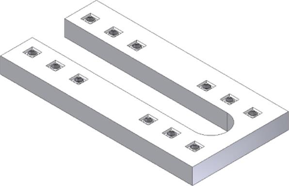
Figure 4.63 The edited part
Repairing Features and Sketches
Ordinarily, you want to create chamfer and fillet features at the end of the overall part-creation process. Creating chamfers and fillets at the end of the process reduces errors caused by feature dependencies associated with these features. In the following exercise, however, you will create a chamfer before creating a hole and then make a change to illustrate both the folly of creating placed features too early in the design and the method of repairing a feature error:
1. On the Get Started tab, choose Open (or press Ctrl+O on the keyboard).
2. Browse for the file mi_4a_063.ipt located in the Chapter 4 directory of your Mastering Inventor 2015 folder and click Open.
3. Select the Chamfer tool (look under the Fillet flyout menu) on the 3D Model tab and select the corner indicated with the red arrow.
4. Set the distance to 30 mm and click the OK button.
5. Click the Start 2D Sketch button and create a sketch on the yellow face.
6. Use the Point tool to place a point near the chamfered corner, dimension it as shown in Figure 4.64, and then click Finish Sketch.
7. Select the Hole tool on the 3D Model tab and place a counterbore hole as shown inFigure 4.64.
8. At this point you decide that the chamfered corner will not work with this design and should have been a rounded corner. To make this change, right-click the chamfer feature in the Model browser and choose Delete from the menu.
9. Because the counterbore hole is dependent on the chamfer, you are prompted with the option to keep it or let it be deleted also. You will choose to keep it by deselecting the Dependent Sketches And Features box and clicking OK.
10.Notice the hole feature in the browser now has a marker symbol next to it indicating it is “sick” and is in need of some repair. Expand the Hole2 feature node, and you will see that the sketch is also marked as “sick.” Right-click the sketch and choose Recover, as shown in Figure 4.65.
11.In the Sketch Doctor dialog box, you will see a list of the issues present in the problematic sketch. Click Next to see the recommendations for resolving this problem. The recommendation is to edit the sketch.
12.Click Next again, and you will see that there is only one treatment option in this case.
13.Click Finish and then click the OK button in the message box informing you that you are being taken to the sketch environment.
Depending on the extent of the error, the Sketch Doctor may offer you the ability to delete objects, close open loops, and so on. Of course, you could have just edited the sketch originally and ended up with the same result in this case. But in cases where you do not know the extent of the problems, the Recover option is often helpful in determining the issue.
14.In the sketch, you will see the unresolved sketch entities highlighted in magenta. Right-click the magenta line and choose Break Link. This breaks the link with the missing chamfer edge but does not fully fix the problem.
15.Select the magenta endpoint(s) and use the context menu's Break Link option on it/them as well. This results in the diagonal line being underconstrained. You have two choices to resolve this:
· Use the Coincident constraint along with the General Dimension tool to lock down the diagonal line.
· Delete the diagonal line and its referencing dimensions and redimension the hole center point off the edges of the base part.
16.Once you have reconstrained the hole center by one of these methods, click Finish Sketch and return to the feature level of the part. Notice that the hole and sketch are no longer “sick.”
17.Choose Fillet on the 3D Model tab and select the same edge previously used by the chamfer to place a 30 mm fillet. Once you have finished, you can close the file without saving changes.
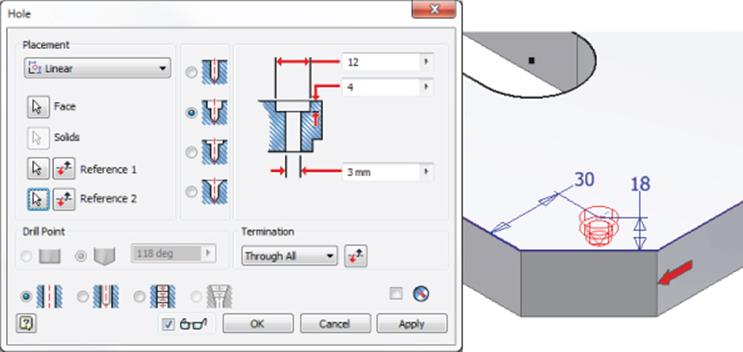
Figure 4.64 Dimensions from the chamfered corner
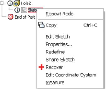
Figure 4.65 Selecting Recover to examine sketches with errors in them
Although there is probably no way you will ever completely avoid having to repair features and sketches, using placed features such as chamfers and fillets as late in the design as possible will go a long way toward reducing these issues. You should also strive to avoid referencing these features with dimensions when they are present.
The Bottom Line
1. Configure options and settings for part modeling. Understanding the settings and options that apply to the modeling environment is essential for getting the results you want from Inventor.
1. Master It You want to configure your options and settings for your sketch environment and then back them up and/or distribute them to other workstations. How would you go about doing this?
2. Create basic part features. In this chapter, you learned how to plan a workflow that allows you to create stable, editable parts that preserve the design intent.
1. Master It You need to create a fairly complex part consisting of many extrusions, revolves, sweeps, and lofts. In addition, you will need to create holes, fillets, chamfers, and other part modifiers. This part may need significant modification in the future by you or by other designers. What considerations will guide your part creation?
3. Use the Extrude tool. The Extrude tool is one of the most commonly used feature tools in the Inventor modeling toolset. Understanding the options and solutions available in this tool will prove useful throughout your designs.
1. Master It Imagine that you need to create an extruded feature but don't know the exact length; instead, you know the extrude will always terminate based on another feature. However, the location of that feature has not been fully determined just yet. How do you get started on the feature?
4. Create revolved parts and thread features. Creating revolved features and parts in Inventor can often resemble the creation of turned parts and features in the real world. Applying thread features to a cylindrical face allows you to specify threads without having to actually model them.
1. Master It Let's say you have a part that you intend to fabricate on a lathe. Although you could create the part with a series of stepped circular extrusions, it occurs to you that the Revolve tool might work also. How do you decide which method to use?
5. Create work features. Using work features, work planes, work axes, and work points enable you to create virtually any part or feature. Work features are the building blocks for sketch creation and use.
1. Master It Your design will require creating features on spherical and cylindrical faces. You need to precisely control the location and angle of these features. How do you do that?
6. Use the Fillet tool. The Fillet tool has a great deal of functionality packed into it. Taking the time to explore all the options on a simple test model may be the best way to understand them all.
1. Master It You are trying to create a series of fillets on a part. You create four sets of edge selections to have four different fillet sizes, but when you attempt to apply them, you receive an error stating that the feature cannot be built. What went wrong?
7. Create intelligent hole features. Although you can create a hole in a part by sketching a circle and extrude-cutting it, this is typically not the recommended approach.
1. Master It You need to create a part with a series of various-sized holes on a plate. You would like to lay out the hole pattern in a single sketch and then use the Hole tool to cut the holes to the sizes required. However, when you select the From Sketch option in the Hole tool, it selects all of the holes, so you think you must need to sketch out the hole pattern as circles and then use the Extrude tool to cut them out. Is this really the way to proceed?
8. Bend parts. You can bend a portion of a part after you define a bend line using a 2D sketch line. You can specify the side of the part to bend; the direction of the bend; and its angle, radius, or arc length.
1. Master It You need to create a model of a piece of rolled tube and would like to specify the bend direction, but when you use the direction arrow, you get a preview in only one direction. How can you get a preview in either direction?
All materials on the site are licensed Creative Commons Attribution-Sharealike 3.0 Unported CC BY-SA 3.0 & GNU Free Documentation License (GFDL)
If you are the copyright holder of any material contained on our site and intend to remove it, please contact our site administrator for approval.
© 2016-2026 All site design rights belong to S.Y.A.