Blender For Dummies (2015)
Part I
Getting Started with Blender
Chapter 4
Working in Edit Mode and Object Mode
In This Chapter
![]() Making changes to your 3D objects
Making changes to your 3D objects
![]() Adding new objects to a scene
Adding new objects to a scene
![]() Saving, opening, and appending .blend files
Saving, opening, and appending .blend files
When working on a scene in Blender, your life revolves around repeatedly selecting objects, transforming them, editing them, and relating them to one another. You regularly shift from dealing with your model in Object mode to doing refinements in Edit mode.
And this process isn’t only for modeling, but also for most of the other heavy tasks performed in Blender. Therefore, you can reuse the skills you pick up in this chapter in parts of Blender that have nothing to do with 3D modeling, such as animating, rigging, compositing, and motion tracking. Just as many of the transform operations work in editors other than the 3D View, many of the concepts here transfer nicely to other parts of Blender. Even if you don't know how to do something, chances are good that if you think like Blender thinks, you'll be able to make a successful guess.
Making Changes by Using Edit Mode
Moving primitive objects around is fun and all, but you're interested in getting in there and completely changing the primitive objects that ship with Blender (described in detail in this chapter) to match your vision. You want to do 3D modeling. Well, you're in the right place. This section introduces you to Edit mode, a concept that's deeply embedded throughout Blender for editing objects. Even though this section is focused mostly on polygon modeling, also called mesh editing, most of the same principles apply for editing curves, surfaces, armatures, and even text.
 When you understand how Blender thinks, figuring out unknown parts of the program is much easier.
Distinguishing between Object mode and Edit mode
In Chapter 3, you do everything in Object mode. As its name indicates, Object mode is where you work with whole objects. However, Object mode isn't very useful for actually changing the internal structure of your object. For example, select (right-click) the cube in the default scene. You know that you can turn it into a more rectangular shape by scaling it along one of the axes. But what if you want to turn the cube into a pyramid? You need to modify the actual components that make up the cube. These changes are made by entering Edit mode.
You can get to Edit mode in one of two ways: with the mouse or with a hotkey (or, if you have the Pie Menus add-on enabled, both!). To use the mouse method, left-click the Object Mode button in the 3D View's header. From the pop-up menu that appears, select Edit Mode (see Figure 4-1). Be aware that if you're working with an object other than a mesh, such as an armature, the contents of this menu may vary slightly to relate more to that object. However, with the exception of Empties (see Chapter 10), Lights, Cameras, and Speakers, all objects have an Edit mode.
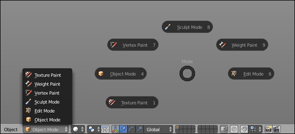
Figure 4-1: On the left, the Mode button allows you to switch between Object mode and Edit mode for a selected object. On the right, the mode selection pie menu (Tab).
 Of course, Blender also has a hotkey to enter Edit mode. Actually, technically speaking, the hotkey toggles you between Object mode and Edit mode. Pressing Tab is the preferred way to switch between modes in Blender, and it’s used so frequently that Blender users often use Tab as a verb and say they're tabbing into Edit mode or Object mode. This language is something you come across fairly often in Blender user forums and in some of Blender's online documentation.
If you have the Pie Menus add-on enabled, pressing Tab no longer toggles between Object mode and Edit mode. Instead, it brings up a pie menu with the option of many modes. It isn't quite as fast as toggling with Tab, but it can be pretty fast if you use the hold hotkey, drag mouse cursor, release hotkey method of using the pie menu (plus you get the added benefit of easily choosing other modes).
Selecting vertices, edges, and faces
After you tab into Edit mode, the cube changes color and dots form at each of the cube's corners. Each dot is a vertex. The line that forms between two vertices is an edge. A face in Blender is a polygon that has been formed by three or more connecting edges.
In the past, faces in Blender were limited to only three-sided and four-sided polygons, often referred to as tris (pronounced like tries) and quads. Since the last edition of this book, Blender — like many other programs — gained support for something called an ngon that can have a virtually limitless number of sides. But don't let Blender's ngon functionality go to your head. There still are some limitations and caveats, as covered in the “A word on ngons” sidebar later in this chapter. Generally, you should think of ngons as a “process” tool. With some exceptions, like architectural models, a finished model should only consist of just three- and four-sided faces. In fact, most detailed character models are made almost completely with quads and an occasional triangle, and all 3D geometry is reduced to triangles when it gets to your computer hardware.
For polygon editing, you can use three different types of Edit modes, sometimes called selection modes: Vertex Select, Edge Select, and Face Select. By default, the first time you tab into Edit mode, you’re in Vertex Select mode.
Two visual cues in the Blender interface clue you in to what selection mode you're using. First, for Vertex Select mode, you can see the individual vertices in the mesh. Second, as Figure 4-2 shows, three new buttons appear in the 3D View's header when you’re in Edit mode. The button on the left (it has an icon of a cube with an orange dot over one corner) is enabled, indicating that you’re in Vertex Select mode.
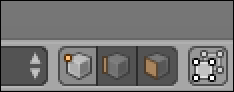
Figure 4-2: The Edit mode Select buttons.
To the right of the Vertex Select button is a button displaying an icon of a cube with a highlighted edge. Click this button to activate Edge Select mode. When you do, the vertices are no longer visible on your mesh. Clicking the last button in this block, which has an icon of a cube with one side marked in orange, activates Face Select mode. When Face Select mode is active, vertices aren’t visible, and each polygon in your mesh has a square dot in the center of it.
Now, you may notice that these buttons are blocked together, kind of like the 3D manipulator buttons. So, as with the manipulator, can you simultaneously activate multiple modes? Absolutely! Simply Shift+left-click the Select mode buttons to get this function. Some Blender modelers like to have Vertex Select and Edge Select modes active at the same time to speed up their workflow. This combined selection mode gives them immediate control at the vertex and edge level, and you can easily select the faces by using Blender's Lasso select (Ctrl+left-click+drag) across two edges. Figure 4-3 shows the default cube in each of the select modes, as well as a Combo Select mode.
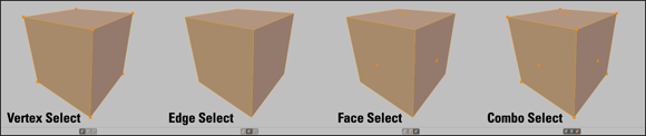
Figure 4-3: Vertex Select, Edge Select, Face Select, and Combo Select modes.
Of course, you can also use a hotkey sequence to access the various select modes. While you’re in Edit mode, if you press Ctrl+Tab, you see a menu that lets you switch between modes. This menu doesn’t let you set multiple modes; for combo selection, you still have to use the buttons in the 3D View's header.
Also, by default, the first time you tab into Edit mode, all vertices/edges/faces are selected. Selecting things in Edit mode works just like selecting anywhere else:
· Right-click any vertex to select it.
· Select and deselect multiple vertices by Shift+right-clicking them.
· Select large groups of vertices by using the Border Select tool (B), Circle Select (C), or Lasso Select (Ctrl+left-click+drag).
· In Border and Circle Select, left-click and drag your mouse cursor to add to your selection. For Border Select, this action draws a box to define a selection area.
· Circle Select is sometimes called Brush Select because selection is like painting. Any vertices that you run your mouse cursor over while holding down the left mouse button are selected.
· Middle-click and drag to subtract from your selection and right-click or press Esc to exit Border or Circle Select.
· To use Lasso Select functionality, Ctrl+left-click and drag your mouse cursor around the vertices you want to select. Anything within that selection region is added to your selection.
And, of course, all these selection tools work in Edge and Face Select modes, as well as in Object mode. Figure 4-4 shows what the various selection tools look like when in use.
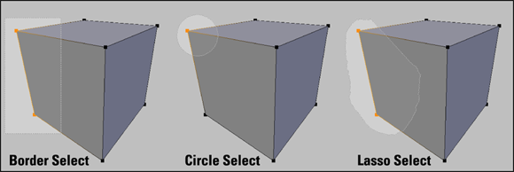
Figure 4-4: Border Select, Circle Select, and Lasso Select.
If you want to select everything (in Object mode, all objects; in Edit mode, all vertices in the active object), you can do so by pressing A. The A hotkey is a toggle, so anything previously selected when you press A is deselected. However, if nothing is previously selected, pressing A selects everything. Using this hotkey, you'll find yourself pressing A until you have either everything or nothing selected.
If you’re using Blender's default settings, you can’t see through your model. You can’t select the vertices, edges, and faces on the back side of the model unless you orbit the 3D View to see those vertices or drop into the wireframe viewport shading setting. (Toggle between wireframe and solid by pressing Z.) On occasion, however, you may find it useful to see (and select) those hidden vertices while in solid viewport shading. To do so, click the Limit Selection to Visible button, sometimes referred to as the Occlude Background Geometry button. Located to the right of the Selection Modes block in the 3D View's header, this button has an icon of a cube with white highlighted vertices on it. (Refer to Figure 4-2.) By default, the Limit Selection to Visible button is enabled, but you can click this button to reveal the vertices, edges, and faces on the back of your model. The hiding of those rear vertices is often referred to as backface culling, and it’s incredibly useful when you're working with complex models. I recommend that you keep it enabled and just temporarily switch to wireframe viewport shading (Z) if you need to quickly see or select those backface vertices.
If you have the Pie Menus add-on enabled, pressing Z doesn't work as a toggle between solid and wireframe views. Instead, pressing Z presents a pie menu with all of the potential shading options available. Like the mode-switching pie menu bound to Tab, this isn't quite as fast as a straight toggle, but it's still pretty fast while also giving you quick access to other viewport shading styles.
Working with linked vertices
Another handy way to select things in Edit mode is by selecting linked vertices. Linked vertices are a set of vertices within a mesh that are connected by edges. In order to understand linked vertices better, go through the following steps:
1. Select (right-click) your default cube in Blender and tab into Edit mode.
All the vertices are selected. If not, press A until they are.
2. With all the vertices selected, press Shift+D or choose Add ⇒ Duplicate from the Tools tab in the Tool Shelf or Mesh ⇒ Add Duplicate from the 3D View's header to duplicate your selection.
Blender creates a copy of your selection and automatically switches to grab mode, allowing you to move the duplicate set of vertices, edges, and faces immediately.
3. Use your mouse to move your new cube off the original and confirm your placement by left-clicking a second time or pressing Enter.
None of the vertices in the original cube are selected. Each cube represents a set of linked vertices. So what if you want to select all the vertices in that cube, too? Sure, you can use the Border, Circle, or Lasso Select tools, but on complex meshes, these tools can get cumbersome. Instead, move to the next step.
4. Place your mouse cursor near any vertex in the original cube and press L.
Blam! All the vertices in both of your cubes are selected.
Of course, the natural next question is, “How do I deselect linked vertices?” That's just as easy. Place your mouse cursor near any vertex on the duplicate cube you created and press Shift+L. All vertices connected to the one near your mouse cursor are deselected. I've found myself using L and Shift+L pretty heavily when trying to place teeth in a mouth I've modeled. These hotkeys are very handy.
Quite a few more selection options are available to you when working with meshes. I describe these selection methods in detail in Chapter 5.
While you’re in Edit mode, you can work only with the current active object. You can’t select and manipulate other objects while you're in Edit mode.
A word on ngons
A longstanding criticism of Blender over the years had been a relative lack of advanced mesh-editing features and tools. Since the release of the last edition of this book, Blender has come a long way, gaining such tools as per-edge beveling, cleaner boolean operations, and the notorious ngon.
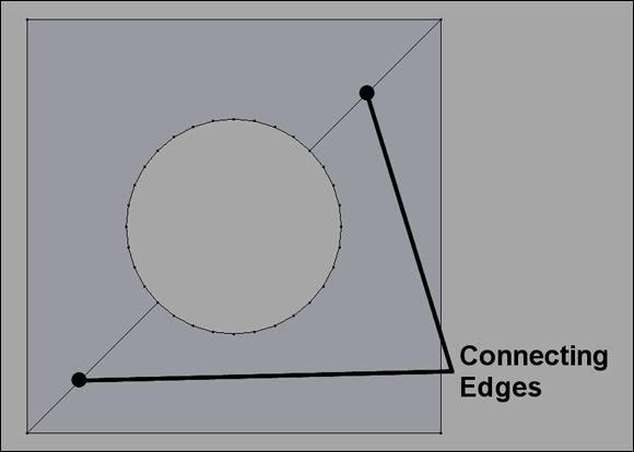
Specific to the ngon, there are still some limitations. For instance, an ngon cannot currently have a hole in it. As the figure shows, to get a hole, you need to have two faces. There need to be edges that connect from the inner ring of vertices to the outer ring.
As mentioned earlier in the chapter, it's best to think of ngons as a process tool. On any mesh that's likely to be used in animation (like a character model) or included in real-time environment like a video game, the finished mesh should be composed of only tris and quads. An exception to this rule of thumb might be for architectural models or models intended to be rendered as still images. Because those meshes won't be deformed by something like an armature or a lattice and they don't have to work in a game engine, often you can get away with leaving ngons in them.
Still Blender's No. 1 modeling tool: Extrude
Besides transform operations (see Chapter 3), the most commonly used modeling tool in Blender is the Extrude function. In meatspace, extrusion is a process whereby some material is pushed through a shaped hole of some sort. When you were a kid, did you ever cut out a shape in cardboard and force clay or mud or Play-Doh through it? If so, you were extruding. If not, you certainly missed out on a good solid five to ten minutes of fun (but don't worry, it's never too late to start).
In 3D, extrusion follows a similar concept, except you don't have to create the hole to extrude through. Instead, that shape is determined by your selection and you can extend that selection in any direction. Use the following steps to extrude:
1. Select the object you want to edit by right-clicking it.
2. Tab into Edit mode.
3. Select the vertices, edges, or faces you want to extrude.
Use any of the selection methods listed in the previous section.
4. Extrude your selection in one of several ways:
1. Use the E hotkey.
2. Left-click Add ⇒ Extrude Region in the Tools tab of the Tool Shelf.
3. Choose Mesh ⇒ Extrude ⇒ Extrude Region from the menu in the 3D View's header.
After you extrude your selection, Blender automatically puts you into grab mode on the newly extruded parts.
Now, if you extrude a polygon, your new extrusion is constrained to move only along its normal. If you don't want this constrained behavior, middle-click your mouse (without moving it) and the constraint is removed, allowing you to freely move your extrusion around.
If you extrude an edge, your extrusion is constrained to a plane perpendicular to your newly extruded edge. If you extrude a single vertex, you're in a free extrude mode that's completely unconstrained. In order to use constraints in this case, you need to use the coordinate system constraint hotkeys described in Chapter 3.
The selected orientation in the Transform Orientation menu is active even if you're transforming with hotkeys. So if you set that menu to the Normal orientation, you can press Z ⇒ Z, and your extruded region is constrained to its face's normal. (Just pressing Z once constrains it to the global Z-axis rather than the face's normal.)
 There are advantages and disadvantages to Blender's extrude function leaping directly into grab mode. The advantages are that you have all the transform functionality, such as axis-locking, snapping, and numerical input immediately available to you. The disadvantage is that, because of this autograb behavior, if you cancel the operation by right-clicking or pressing Esc, the newly extruded vertices, edges, or faces are still there, just located in exactly the same place as the vertices, edges, or faces that they originated from.
For this reason, if you cancel an extrude operation, make sure that your duplicate vertices, called doubles, are no longer there. A quick way to check is to press G after you cancel your extrusion. If it looks like you're extruding again, you have doubles.
You can get rid of doubles in a variety of ways:
· If the canceled extrusion operation was the last thing you did, undo it by pressing Ctrl+Z. This solution usually is the quickest.
· If you still have the doubles selected, delete them. You can activate the delete operation with hotkeys (X or Del), clicking Remove ⇒ Delete Vertices in the Tools tab of the Tool Shelf, or by going to Mesh ⇒ Delete Vertices in the 3D View's header. If you use the delete hotkey, you see a menu where you decide what elements of the mesh you want to delete. In this case, you choose Vertices. The disadvantage of this method is that it also removes the faces created by those vertices.
· If you’re unsure whether you have doubles from previous canceled extrusions, use Blender’s special Remove Doubles function:
1. In Edit Mode, select all by choosing Select ⇒ (De)select All from the 3D View's header or pressing A until all vertices are selected.
2. Press W ⇒ Remove Doubles, and Blender removes all doubles from your mesh.
You can find this option in Mesh ⇒ Vertices ⇒ Remove Doubles in the 3D View's header, as well as the Tools tab of the Tool Shelf (Remove ⇒ Remove Doubles).
If you have Blender's mesh auto-merge feature enabled (it's disabled by default, but can be enabled in the 3D View's header menu in Mesh ⇒ AutoMerge Editing or by a button in the 3D View's header with an icon of two arrows pointing at each other), you might expect that duplicate vertices automatically are removed/merged if you have a canceled Extrude operation. This isn't the case. Those extruded vertices will remain in place until you move them, so don't assume that you're automatically safe from having doubles when auto-merge is enabled.
If you look in the Mesh menu of the 3D View, you have more than one Extrude option. A second Extrude operation, called Extrude Individual (Shift+E), works, depending on which selection mode you chose. If you're in Face Select mode, then the Extrude Individual operation extrudes each face you selected along its independent normal. Likewise, if you're in Edge Select mode, Extrude Individual extrudes each edge you selected independently of one another. And the same principle works on vertices if you're in Vertex Select mode and choose Extrude Individual.
When you're modeling, the most common type of extrusion you want is related to what you selected. For example, if you want to extrude an edge, you select that edge, or if you select a group of faces, chances are good that you want to extrude that as a region. As expected, Blender has shortcuts for these common modeling tasks.
Blender also has an even faster way to do an extrusion on a mesh. This is a great feature if you're making an organic model that consists of a long series of extrusions, such as a tree or the profile of a wine glass. To perform a quick extrusion:
1. Select your object and tab into Edit mode.
2. Select the vertices, edges, or faces you want to extrude.
3. Ctrl+left-click where you’d like the extrusion to end.
Blender automatically decides what kind of extrusion you want and extrudes your selection right where you’d like. Working this way is particularly useful when you’re doing a series of multiple extrusions, one right after the other, such as when you’re roughing out a shape by “drawing” with vertices or edges.
For some simple examples of how to make a model using the extrude operator, visit the tutorials I've placed on www.blenderbasics.com.
Modeling organically with the Proportional Edit tool
Often, when you’re modeling organic objects or objects with smoothly curved surfaces, such as characters, creatures, or sports cars, you may find yourself pushing and pulling a bunch of vertices to obtain that smooth surface. You can simplify this process by using Blender's Proportional Editing feature, sometimes referred to as the PET, for Proportional Editing Tool.
If you come from another 3D package, you might recognize proportional editing as being similar to the soft select feature. You activate proportional editing by left-clicking the Proportional Editing mode button, which looks like two gray concentric circles in the 3D View's header. The hotkey for this operation is O. Now when you perform a transform operation, a circle appears around your selection. Your transformation influences any vertices that are within this circle with a gradual falloff.
You can adjust the influence circle used by proportional editing by scrolling your mouse wheel or pressing Alt+Numpad Plus (+) and Alt+Numpad Minus (-). Additionally, you can control how gradual the falloff is by left-clicking the button with the curve icon next to the Proportional Editing mode button in the 3D View's header or by cycling through the options by pressing Shift+O.
The proportional editing feature in Blender has one more useful option. On complex meshes, you may want to use proportional editing on one set of vertices that are connected to each other, but not to other nearby vertices in the same mesh. For example, say that you've modeled a character and her hand is at her side near her leg, and you’d like to smoothly edit her hand and pull it away from the leg without having to gradually adjust the vertices of the arm. Proportional editing is the perfect tool for this job. However, when you try to use proportional editing as described in the previous paragraphs, other leg vertices are within the influence circle, and you end up moving those unintentionally. Wouldn't it be great if proportional editing could understand that you only want to move the hand? Well, I have good news: It can! Click the Proportional Editing mode button in the 3D View header and select Connected or press Alt+O. The Connected option for proportional editing only adjusts vertices that are connected to each other within its influence area. Neat, huh?
Proportional editing works in Object mode as well. This capability can be really handy, but it can sometimes yield undesirable results if you want to use this feature only while in Edit mode. For this reason, double-check your 3D View's header before performing a transformation to see whether proportional editing is enabled.
Adding to a Scene
There's got to be more to life than that plain default cube, right? Indeed, there is. Blender offers a whole slew of primitives, or basic objects, to build from.
Anytime you add a new object in Blender, the origin of that object is located wherever you placed the 3D cursor.
Getting to know the toolbox menu
In previous versions of Blender, one of the quickest ways to access any feature in the 3D View is with a toolbox that was activated when pressing spacebar. To access the toolbox, you only had to hover your mouse in the 3D View and press spacebar. Sadly, this feature is no longer a default. Pressing spacebar now only pops up Blender's integrated search menu.
Fortunately, all is not lost! You can still have your good old toolbox back, thanks to Blender's Add-ons system (see Chapter 2). Simply go to the Add-ons section of User Preferences (Ctrl+Alt+U) and enable the Dynamic Spacebar Menu add-on (it's in the 3D View category). With this add-on enabled, when you go back to the 3D View and press spacebar, a menu pops up with a variety of options beneath your mouse cursor.
The actual content of the menu changes, depending on context like what type of object you have selected or if you're in Edit mode or Object mode, but it's mostly a condensed form of what you find in Blender's Add and Object menus. If you want to use the integrated search feature that is normally bound to spacebar, that option is still there at the top of the Dynamic Spacebar Menu. Click that first option, and the familiar search menu appears.
You may notice that for pop-up menus like the Dynamic Spacebar Menu (see sidebar), Blender places the last menu option you choose directly under your mouse cursor. This workflow feature helps increase your speed. The idea is that you often want to do the same task multiple times in a row. Blender makes repetitive tasks easier by shortening the distance you have to move your mouse with each function.
Adding objects
To add a new object to your scene, hover your mouse cursor over the 3D View and use the Shift+A hotkey. From the menu that appears, choose the type of primitive you want to put into the scene. You have the following choices:
· Mesh: Meshes are polygon-based objects made up of vertices, edges, and faces. They’re the most common type of modeling object used in Blender. Chapter 5 goes into high detail on modeling with meshes. The other types of primitives listed here are covered in Chapter 6.
· Curve: Curves are objects made up of curved or straight lines that you manipulate with a set of control points. Control points are similar to vertices, but you can edit them in a couple of ways that vertices can't be edited. Blender has two basic forms of curves, Bèzier curves and NURBS (Non-Uniform Relational B-Spline) curves. You can also use curves as paths to control other objects.
· Surface: A surface is similar to a mesh, but instead of being made up of vertices, edges, and faces, surfaces in Blender are defined by a set of NURBS curves and their control points.
· Metaball: Metaball objects are unique primitives with the cool ability to melt into one another and create a larger structure. They’re handy for a variety of effects that involve blobby masses, such as clouds or water, as well as quick, rough, clay-like models.
· Text: The text object allows you to bring type into your 3D scene and manipulate it like other 3D objects.
· Armature: Armature objects are skeleton-like structures that consist of linked bones. You can use the bones in an armature to deform other objects. The bones are particularly useful for creating the puppet-like controls necessary for character animation. There's a lot more detail on armatures in Chapter 11.
· Lattice: Like armature objects, you can use lattices to deform other objects. They’re often used in modeling and animation to squash, stretch, and twist models in a non-permanent way. Lately, lattices are used less and less in Blender because users have gained the ability to deform objects with curves and meshes, but they're still very useful.
· Empty: The unsung hero of Blender objects, Empties don’t show up in finished renders. Their primary purpose is merely to serve as a reference position, size, and orientation in 3D space. This basic purpose, however, allows them to work as very powerful controls.
· Speaker: If you're using Blender to create a real-time environment such as a video game, you can use a speaker object in your scene to give players an immersive experience with 3D sound.
· Camera: Like real-world cameras, camera objects define the location and perspective from which you’re rendering your scene.
· Lamp: Lamp objects are necessary for lighting your scene. Just like in the physical world, if you don't have any light, you don't see anything.
· Force Field: In the simplest terms, a force field is an Empty that acts like the source of some physical force such as wind or magnetism. Force fields are used primarily with Blender's integrated physics simulation. I briefly touch upon force fields in Chapter 13.
· Group Instance: A group is a set of objects you define as being related to each other in some way. The objects in a group don’t have to be the same type. Groups are handy for organization as well as appending sets of objects from external files.
When adding new objects, be aware of whether you’re in Object mode or Edit mode. If you add while in Edit mode, then your addition options are limited to the type of object you're editing. That is, if you're in Edit mode on a mesh, you can only add new mesh primitives. Also, your new object’s data is joined with the object you’re editing. If you don't want the object data to join, then make sure that you tab back to Object mode before adding anything new.
Meet Suzanne, the Blender monkey
Many 3D modeling and animation suites have a generic semi-complex primitive that is used for test renders, benchmarks, and examples that necessitate something a little more complex than a cube or sphere. Most of these other programs use the famous Utah teapot as their test model.
Blender has something a little more interesting and unique. Blender has a monkey head that's affectionately referred to as Suzanne, a reference to the ape in two of Kevin Smith's films: Jay and Silent Bob Strike Back and Mallrats (close to the end). You can add Suzanne to your scene by pressing Shift+A ⇒ Mesh ⇒ Monkey. If you look through the Blender community's forums and much of Blender's release documentation, you see Suzanne and references to her all over the place. In fact, the annual awards festival at the Blender Conference in Amsterdam is called the Suzanne Awards. Figure 4-5 shows a test render featuring Suzanne.
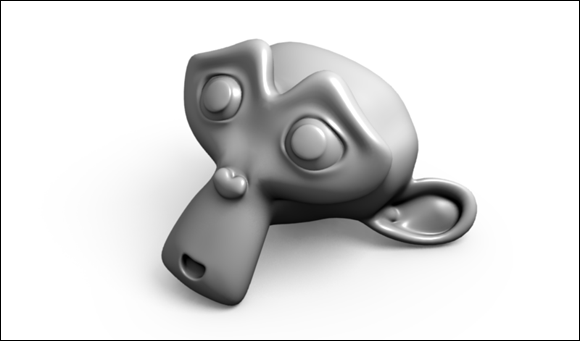
Figure 4-5: Suzanne!
If you absolutely must have a teapot as your test mesh, you can have that, too. It's in the Extra Objects add-on for meshes. Enable this add-on by going to the Add-ons section of User Preferences (Ctrl+Alt+U or File ⇒ User Preferences) and looking in the Add Mesh category. Once enabled, you can find the teapot in the Add menu (Shift+A ⇒ Mesh ⇒ Misc Objects ⇒ Teapot+).
Joining and separating objects
In the course of creating models for your scenes, you may need to treat separate objects as a single one, or break the parts of a single object into their own distinct objects — for example, you may accidentally add a new primitive while you’re still in Edit mode. Of course, you can simply undo, tab into Object mode, and re-add your primitive, but why act like you made a mistake and go through all those extra steps?
There's another way. When you add a new primitive while in Edit mode, all the elements of your new primitive are selected, and nothing from your original object is selected. If only there were a command that would let you break this primitive away from this object and into an object of its own. Fortunately, there is. While in Edit mode, press P ⇒ Selection, and your new primitive is separated into its own object. You can also access this function in the 3D View's header menu (Mesh ⇒ Vertices ⇒ Separate ⇒ Selection).
Tab back into Object mode and select (right-click) your new object. Its origin is located in the same place as its original object's origin. To put the origin of your new object at its actual center, press Shift+Ctrl+Alt+C ⇒ Origin to Geometry or click Object ⇒ Transform ⇒ Origin to Geometry in the 3D View's header. This Origin to Geometry operation checks the size of your object and calculates where its true center is. Then Blender places the object's origin at that location.
You can also specify that the object's origin be placed wherever your 3D cursor is located by pressing Shift+Ctrl+Alt+C ⇒ Origin to 3D Cursor or clicking Object ⇒ Transform ⇒ Origin to 3D Cursor.
A third option is similar to Origin to Geometry, but it moves the object's content rather than the origin itself. Do this operation by clicking Object ⇒ Transform ⇒ Geometry to Origin (Shift+Ctrl+Alt+C ⇒ Geometry to Origin).
As expected, you can also join two objects of the same type into a single object. To do so, select multiple objects. In Object mode, you can use the Border Select or Lasso Select tools, or you can simply Shift+right-click objects to add them to your selection. The last object you select is considered your active object and is the object that the others join into. With your objects selected, join them by pressing Ctrl+J or clicking Object ⇒ Join from the 3D View's header.
You can join objects of the same type only. That is, you can join two mesh objects, but you can't join a mesh object with a curve object. Using parenting or groups (discussed later in this chapter in the section “Discovering parents, children, and groups”) may be more appropriate.
Understanding the difference between joins and booleans
This is a bit of a terminology thing. If you've never worked in 3D computer graphics before, you might expect that a join operation on two objects would result in a single, connected mesh. That's not quite how it works. Earlier in this chapter, I explain that an object can consist of both linked and unlinked elements. There's no requirement that, for example, all the vertices in a mesh object are linked by faces and edges. When you join two separate objects using Ctrl+J, you're really just bundling them into the same object datablock. You aren't changing any of the mesh data.
To actually merge meshes into a single linked unit, you need to either
· Edit the mesh data manually — merging vertices and creating new edges and faces as necessary.
· Use a boolean — an operation that does a logical (for example, and, or, intersection) combination of two meshes.
In Blender, booleans are done with a modifier. Really, I recommend only using the Boolean modifier as a last resort; it can really mess up your mesh topology (how vertices and faces are laid out over your mesh). Modifiers are covered in more detail in Chapter 5.
Creating duplicates and links
In the section “Working with linked vertices,” earlier in this chapter, an example involved duplicating your selected vertices by using Shift+D (or Mesh ⇒ Add Duplicate). As you may expect, this operation also works in Object mode (the hotkey is the same — Shift+D — but the menu item is slightly different at Object ⇒ Duplicate Objects). This duplication method is great if you intend on taking an existing object and using it as a starting point to model another, more individualized object by tweaking it in Edit mode. However, suppose that you want your duplicated object to be identical to the original in Edit mode. And wouldn't it be nice if, when you do go into Edit mode, your changes happen to the original as well as to all the duplicates? For duplicated objects that you have to edit only once, you want to use the power of linked duplicates. Linked duplicates are objects that share the same internal datablocks.
Linking objects, in this case, is different from the linked vertices described earlier in this chapter. The fact that the same word is used in a couple different ways can be a bit confusing, but there's a mnemonic that can help you keep things straight:
· Linked vertices (as described earlier in the chapter) are specific to Edit mode.
· Linked objects (as described in this section) are specific to Object mode.
Linking data between objects
Linked duplicates are similar to what other programs call instance copies. The process to create a linked duplicate is pretty straightforward:
1. Select the object you want to duplicate by right-clicking it.
2. With the object selected, press Alt+D or Object ⇒ Duplicate Linked from the 3D View's header.
From here, the behavior is just like regular duplication.
The object is automatically in grab mode.
3. Place the object with your mouse and confirm its new location by left-clicking or by pressing Enter.
You can use a few other methods to verify that this duplicated object is, in fact, a linked duplicate. The easiest way is to tab into Edit mode on the original object or on any of the duplicates. When you do, all the linked objects appear to go into Edit mode, and any changes you make here automatically update all the other objects immediately. Figure 4-6 shows three linked duplicates of Suzanne being simultaneously modified in Edit mode.
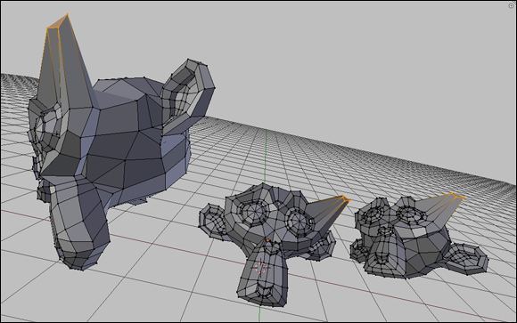
Figure 4-6: Editing duplicated Suzannes!
A second way to verify the linked status of duplicates is to look in the Object Data section of the Properties editor. At the top of this panel, look at the top datablock field, which is the Datablock Name field. If a number appears to the right of the name, it is the number of objects linked to this datablock. In other words, this number is the count of your linked duplicates. Figure 4-7 shows how this panel looks when one of the Suzannes in the previous figure is selected.
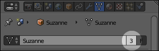
Figure 4-7: Three objects are sharing this datablock.
Another way to visualize linked data in Blender is to consider that Blender treats the internal structure of its .blend files like a database. As I cover in Chapter 2, all datablocks in your scene — including objects, materials, and mesh data — can be linked and shared between one another. The real power comes in allowing multiple objects to share with each other. For example, you can have objects share materials, mesh data, actions, and even particle systems. And different scenes can even share objects! Taking advantage of this feature not only reduces the size of your .blend files, but it can also seriously reduce the amount of redundant work you have to do. Figure 4-8 shows a data schematic for the previous scene involving the three linked duplicates of Suzanne. You can see how the datablocks in that scene relate to one another.
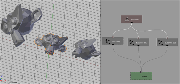
Figure 4-8: A data schematic of linked Suzannes.
So say that you've been using Blender for a while without knowing about linked duplicates, and your .blend file is rife with redundant mesh data. Is there a way to get rid of those regular duplicates and make them linked duplicates? Of course! Follow these steps:
1. Select all the objects that you want to share the same data.
Use any of the selection tools available to you (Border, Circle, Lasso, and Shift+right-click). All the objects must be of the same type, so you can't have a mesh object and a curve object share the same datablock.
2. With each desired duplicate selected, select (Shift+right-click) the object with the datablock that you want to share with the others.
This step makes that last-selected object the active object.
3. Press Ctrl+L or Object ⇒ Make Links from the 3D View's header menu to bring up the Make Links menu.
4. Choose the third option from the top, Object Data.
Kerplooie! All the selected objects now link to the same internal data.
Figure 4-9 shows the preceding process, using a bunch of cubes and a Suzanne object.
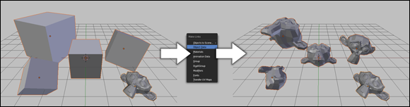
Figure 4-9: Linking cubes to Suzanne.
You probably noticed that the Make Links menu had some other interesting options. Following is a description of what each one does:
· Objects to Scene: If you have multiple scenes in your .blend file, you can make those scenes share the same objects. This option reveals another menu with all the scenes in the file. By choosing a scene, the object or objects that you selected have linked duplicates created in that scene.
· Object Data: This option is the one you used in the preceding example. Object Data links the internal data — be it a mesh, a curve, a lamp, or nearly any other object — of the selected objects to the internal data of the active object. For this option to work, all the selected objects must be of the same type. This is the only option where having objects of the same type is important.
· Materials: Choosing this option causes all the selected objects to share the same material settings. For more information on materials, see Chapter 7.
· Animation Data: This option relates directly to animation. It's the set of keyframes that describe the motion of an animated object, called actions. (Chapter 12 has more information on actions.) Choosing this option causes all your selected objects to share the same actions as the active object.
· Group: In the “Discovering parents, children, and groups” section of this chapter, you see how Blender allows you to organize your objects into groups. Choosing this option puts all of the selected objects in the same group.
· DupliGroup: One cool thing about groups is that you can generate them as duplicated instances in a few ways. One of those ways is as a dupligroup. Choosing this option allows multiple objects to share the same dupligroup.
· Modifiers: A modifier is an operation that Blender performs on your object's data without permanently changing that data (see Chapter 5). Modifiers allow you to have very complex models that are still manageable, while retaining the simple editability of the original data. Unlike the other options in the Make Links menu, this option doesn't link the same modifier to multiple objects. What it really does is copy the modifier and its settings from one object to another. In the future, you may be able to treat modifiers as linkable datablocks, but that is not currently the case.
· Fonts: This option is specific to Text objects. If you want to change the font on a bunch of text objects at the same time, it can be a pretty tedious manual process. However, by choosing this option, you can quickly set the same fonts for all selected Text objects.
· Transfer UV Maps: UV maps (covered in Chapter 8) are used for mapping a 2D image to the surface of your 3D object. You can share UV coordinate layouts between multiple 3D objects that share the same mesh topology (objects that have the same number and connections between vertices, but not necessarily the same vertex positions).
Like modifiers, this doesn't really link datablocks; it really copies the UV layout from one mesh to the other. If you edit the layout after that, it only has an effect on the active object.
Unlinking datablocks
Of course, if Blender has a way to create links and duplicates, you’d logically (and correctly) think that you can convert a linked duplicate into an object with its own, non-shared datablock. In Blender, this process is called giving that datablock a single user.
The reason for the single user terminology goes back to how these datablocks are tied together. From the perspective of the datablock, each object that's connected to it is considered a user. Refer to Figure 4-9: Each Cube object is a user of the Suzanne datablock. By choosing to use the Make Single User operator, you’re effectively telling Blender to duplicate that datablock and make sure that it connects to only a single object. To make an object have single user data, select the object you want and then press U or go to Object ⇒ Make Single User in the 3D View's header. You see a menu with the following options:
· Object: Use this option when you have an object that is linked to multiple scenes and you want to make changes to it that appear only in the specific scene that you’re currently working on.
· Object & Data: For cases like the preceding example with the linked Suzanne meshes where you have a linked duplicate that you’d like to edit independently of the other meshes, choose this option. Doing so effectively converts a linked duplicate into a regular duplicate.
· Object & Data & Materials+Tex: If you have an object that is not only sharing internal object data with others, but also sharing material settings, choose this option, and both of those datablocks are duplicated and singly linked to your selected object. Using this option is a pretty good way to make sure that your selected object isn't sharing with any other objects at all.
· Materials+Tex: In cases where you no longer want to share materials between objects, choosing this option makes sure that your selected object has its own material settings independent of all the other objects.
· Object Animation: This option is the inverse of the Make Links ⇒ Animation Data option. If your selected object is sharing actions with any other objects, choosing this option makes sure that it has actions of its own.
Another way to make object data a single user is to use the datablock buttons in Blender's interface. In Figure 4-7, the number 3 is highlighted, showing that three objects share that particular datablock. If you left-click that number, you make that a single user datablock. This little button shows up in many places throughout the Blender interface. The datablocks that it operates on vary with context (for example, seeing this button in Material Properties means that it's working on a material datablock; seeing it in the Dopesheet means that it's working on actions, and so on), but it always means the same thing: Create a datablock like this one that has only the selected object as its user.
There is one other way to make object data a single user. Use the Outliner. Right-click an object data entry and choose Make Single User from the menu that appears. There are a few datablocks (such as material actions) where this is the only clear way to make them single user.
Discovering parents, children, and groups
Working in 3D, you may encounter many situations where you’ll want a set of objects to behave like a single organizational group. Now, if the objects are all the same type, you can join them into a single object, but even with the L and Shift+L linked selection operations in Edit mode, this approach can get unwieldy. And joining them into a single object requires you to tab into Edit mode each time you want to work with an individual item. That's not very efficient, and it doesn't give you the flexibility of working with different kinds of objects as a single unit. The better way to organize your objects is with parent-child relationships or with groups.
Establishing parent-child relationships between objects
Creating parent-child relationships between objects, or parenting in Blenderese, organizes the objects hierarchically. An object can have any number of children, but no object can have more than a single parent:
1. To make an object a parent, first select the objects you want to be children.
They don’t have to be of the same type.
2. Make your last selection (the active object) the object that you want to become the parent.
3. Press Ctrl+P ⇒ Object or click Object ⇒ Parent ⇒ Object in the 3D View's header menu.
After you confirm the operation by left-clicking or pressing Enter, Blender adds a dotted line from the origin of each child object to the origin of the parent. Now when you select just the parent object and perform a transform operation on it, it affects each of its children. However, if you select a child object and transform it, none of the other children or the parent object are influenced.
A good mnemonic device for remembering the correct order for selecting objects when you want to create a parent-child relationship is to think of the order people get off of a boat when they're abandoning ship: “Children first!”
Parenting is a great way to organize a set of objects that have a clear hierarchy. For example, say that you've modeled a dinner table and the chairs to go around it. Now you want to place that table and chairs in a room, but the room is scaled much smaller than the table and chairs. Rather than select, scale, grab, and move each object into place, you can parent each of the chairs to the table. Then you can just select and transform the table. When you do so, all the chairs transform right along with it, as if they were a single object! Woohoo! Figure 4-10 illustrates this example.
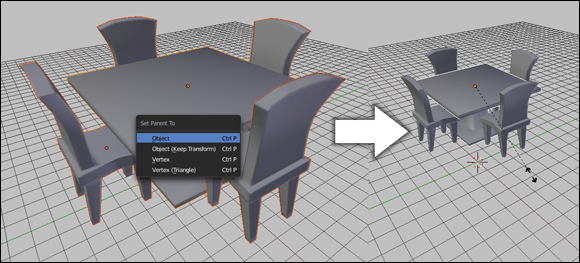
Figure 4-10: Parenting some chairs to a table and placing them in a room.
To clear a parent relationship, the process is only a click and a hotkey:
1. Select the child object that you want to remove from the hierarchy.
2. Press Alt+P or click Object ⇒ Parent ⇒ Clear Parent in the 3D View's header to clear the parent relationship.
If you use the hotkey, you see a pop-up menu with three options:
· Clear Parent: This option removes the parent-child relationship between your selected object and its parent. If the parent object was transformed after the parenting took place, the cleared child jumps back to the position, scale, and rotation that it was in before it was parented.
· Clear and Keep Transformation (Clear Track): This option behaves the same as Clear Parent, except any transformations that were made while the selected object was a child are applied. This means that the cleared child does not snap back to its original pre-parented state.
· Clear Parent Inverse: This option is a bit tricky to understand. It actually does not remove the link between the selected child object and its parent. Instead, it basically clears the parent's transformation from the child. Clear Parent Inverse is handy for situations where you've transformed an object before parenting it, and you want it to relate to the parent as if it had not been transformed prior to parenting. To be honest, I don't use this option very often, but it's certainly good to have around when you need it.
Another quick way of parenting within Blender is from the Outliner. Within the Outliner, you can left-click the icon of any object and drag it over the name of another object in the Outliner (essentially dropping it in like copying a file into a folder on your computer's file browser). That action automatically creates a parent-child relationship between the two objects. On complex scenes, this is an extremely handy trick.
Creating groups
Of course, under some circumstances, parenting doesn't make sense for organizing a set of objects. A good example is a lighting setup that you want to adjust and reuse. Sure, you can rationalize that perhaps the key light is the most important light and therefore should be the parent, but that logic is a bit of a stretch and doesn't make much sense in more complex setups.
For these cases, Blender's grouping feature is ideal. To create a group, select all the objects you want to include in the group and press Ctrl+G or click Object ⇒ Group ⇒ Create New Group. All the objects in the group share a green selection outline rather than the default orange, to indicate that the object is a member of at least one group. The notion of an object being a member of at least one group highlights another example of how grouping and parenting differ. Whereas an object can have only one parent, it can be a member of any number of groups. If you go to the Object ⇒ Group menu, you have a number of options:
· Create New Group (Ctrl+G): This option is always available and creates a new group, adding your selected objects to it.
· Remove from Groups (Ctrl+Alt+G): This option is always available, and choosing it removes the selected objects from any groups they may be a member of. Removing all objects from all groups doesn’t delete those groups while your Blender session is still active.
· Remove from All Groups (Shift+Ctrl+Alt+G): This is a quick shortcut to remove the selected objects from all of the groups they may be a member of.
· Add Selected to Active Group (Shift+Ctrl+G): To use this feature, you need the active object to be the member of a group. Then any objects you have selected become members of all the groups your active object is a member of.
· Remove Selected from Active Group (Shift+Alt+G): Choose this option, and all your selected objects (including the active object) are removed from any groups in the active object.
Furthermore, it's worth knowing that groups have names. Check out the Object section of the Properties editor. This section contains a panel named Groups, listing the groups to which the selected object belongs. Left-click any group name to change it to something more relevant to that group's organization. Clicking the X next to the group name removes the selected object from that group. The set of layer buttons under the group name, labeled Dupli Visibility, have a special application for larger, more complex projects that involve linking groups between .blend files. Basically, if some objects in your group are on a layer that isn’t enabled in these buttons, then those objects aren’t visible when the group is linked to another file.
Many game engines and other 3D applications have a notion of grouping that's very different from Blender's grouping. They tend to treat all members of a group as a single unit, regardless of which one gets selected. They also tend to treat groups hierarchically; an object can only belong to one group (in turn, that group can be a member of another group, but the base object is still only a member of one). In fact, this behavior is a lot more like parenting in Blender than grouping. To mimic this behavior more seamlessly, use the following steps:
1. Create an Empty object near the center of your “grouping” of objects and display it as a cube (Shift+A ⇒ Empty ⇒ Cube).
2. Adjust the size of the Empty (Empty Properties ⇒ Size) to roughly include all of the objects in your grouping.
3. Name the Empty something clever to indicate the grouping's name (Object Properties).
4. Make all objects you’re grouping a child of the Empty (select each object, select the Empty, Ctrl+P ⇒ Object).
With this bit of legwork done, you can select the Empty's cube outline to transform your whole grouping. Even better, your grouping will be hierarchically organized in the Outliner. Many game engine export scripts properly recognize and translate this structure to their native means of grouping.
Selecting with parents and groups
When you're using parenting and groups, you gain the ability to rapidly select your objects according to their groupings. Press Shift+G, and you see a pop-up menu with a variety of options:
· Children: If you have a parent object selected, choosing this option adds all that object's children to the list of selected objects.
· Immediate Children: Similar to selecting all children, except this option traverses down the hierarchy by one step only. Children of children are not added to the selection.
· Parent: If the object you've selected has a parent object, that parent is added to the selection.
· Siblings: This option is useful for selecting all the children of a single parent. It does not select the parent object, nor does it select any children that these sibling objects may have.
· Type: This option is useful for making very broad selections. Use Type when you want to select all lamps or all meshes or armatures in a scene. This option bases its selection on the type of object you currently have selected.
· Layer: Use this option to select objects that live on the same layers. If an object is on multiple layers, any objects that share any layer with your selected object are added to the selection.
· Group: This option adds to the selection any object that is in the same group as your selected object. If the selected object belongs to more than one group, a secondary pop-up menu displays each of the group names for you to choose from.
· Hook: If you've added hooks, which are objects that control selected vertices or control points in an object, this option selects them. You can find more information on hooks in Chapter 11.
· Pass: Similar to layers, objects may have a Pass Index value that is useful for compositing and post-production work in Blender. Choosing this option selects any objects that share the active object's Pass Index value. You can find more information on passes and the Pass Index in Chapter 15.
· Color: This option allows you to select objects that have the same color, regardless of whether or not they link to the same material datablock.
· Properties: Blender gives you the ability to add custom properties to objects (like a Health property for characters in a game). Choose this option, and all objects that have the same properties are selected.
· Keying Set: Keying sets (covered more in Chapter 10) are used for organizing a group of objects and properties for animation. They're properties that all have keyframes set at the same time. This option selects all objects that share the current object's keying set.
· Lamp Type: This option is similar to the Type option, though it's specific to lamps. If you currently have a lamp selected, choosing this option also selects any lamps that are of the same type (such as Spot, Point, Area, and so on).
Saving, opening, and appending
Quite possibly the most important feature in any piece of software is the ability to save and open files. Having quick access to saving and opening files was especially useful for early versions of Blender, which lacked any sort of undo function. Blender users learned very quickly to save early, save often, and save multiple versions of their project files. One benefit is that Blender reads and writes its files very quickly, even for complex scenes, so you very rarely ever have to wait more than a second or two to get to work or save your project.
To save to a new file, choose File ⇒ Save As from the main header or use the Shift+Ctrl+S hotkey. If you're used to older versions of Blender, you can still use the F2 hotkey to do the same thing. One strange thing that you may notice is that Blender doesn’t bring up the familiar system save dialog box that Windows, Mac, or Linux uses. This is for three reasons. First and foremost, such a dialog box violates Blenders non-blocking interface concept (see Chapter 1). Not only that, but by Blender using its own File Browser interface, you can be guaranteed that no matter what kind of computer you use, Blender always looks and behaves the same on each platform. And as a third point, the Blender File Browser has some neat Blender-specific features that aren't available in the default OS save dialog boxes.
Take a look at the File Browser shown in Figure 4-11. The header for this editor features an assortment of buttons for navigating your hard drive's directory structure and filtering the files shown. If you've used the file browser that comes with your operating system, most of these buttons should be familiar to you. The majority of the options in the side region on the left of the File Browser are there to give you shortcuts to various locations on your computer's hard drive. However, at the bottom of the side region is a set of check boxes that change, depending on whether you're loading or saving your project.
The largest portion of the File Browser is devoted to actually showing files and folders. The topmost text field in this region is the current path on your hard drive to the folder/directory you’re currently viewing. Below this text field is the text field for the actual name of your file. In this field, type your project’s name. Pressing Enter or clicking the Save As Blender File button in the upper right corner saves the file for you. Below this button is a list of the files in the current folder. If you aren't familiar with Linux and Unix, the first item in this list might seem odd to you. This double-dot (..) is a shortcut for going up in the directory structure. Left-clicking it is just like clicking the Up button in the File Browser's header. It takes you to the parent directory of the one you're currently viewing. Figure 4-11 shows the Blender File Browser and labels the various buttons in it.
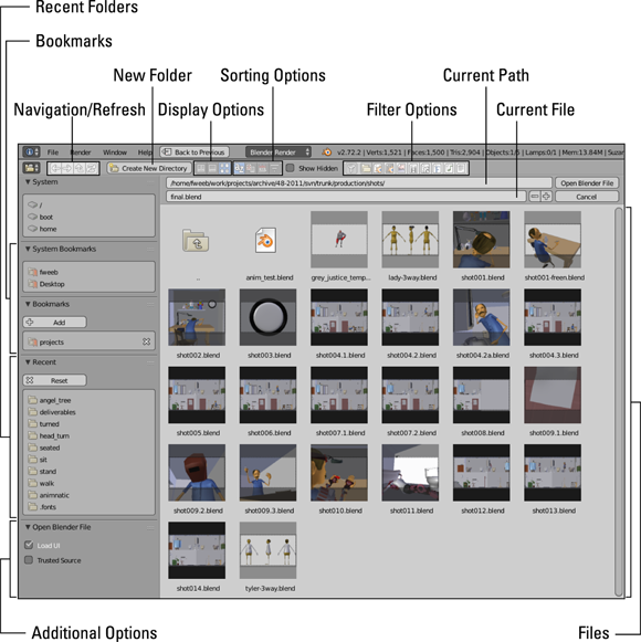
Figure 4-11: The Blender File Browser.
Saving after the first time
After you save your .blend file once, saving gets much quicker. To do a fast save while you’re working, choose File ⇒ Save from the main header or, even faster, press Ctrl+S and confirm the overwrite by left-clicking or pressing Enter.
On larger projects, however, you may not want to continually overwrite the same file. In those cases, it's often more favorable to save progressive versions of your project as you work on it. You can open the File Browser and type a new name for each version — but it’s slow. Often, when people save versions of a project file, they usually append a number to the end of the filename (for example, file1.blend, file2.blend, file3.blend, and so on). Blender knows this habit and aims to help you out.
The ultra-fast way is with the following hotkey sequence: F2 ⇒ Plus (+) ⇒ Enter. Pressing Plus (+) while in the File Browser automatically appends that number to your filename for you. And if the file already has a number, it increments it by one. For logical consistency, pressing Minus (-) decrements that value. How's that for speedy? If you prefer to use your mouse, you can also perform the same function in the File Browser by left-clicking the Plus (+) and Minus (-) buttons after the filename text field.
Opening a file
Opening a .blend file is a straightforward task. Choose File ⇒ Open from the main header or press Ctrl+O. If you've used older versions of Blender, the F1 hotkey still works, too. The File Browser loads again and allows you to choose which file you want to load. To load the file, left-click the filename and click the Open File button in the upper right corner. If you have a large monitor and you don't want to move your mouse that far or you're just interested in speedy shortcuts, you can quickly select and open a file by double-clicking it.
Appending from an external file
Now, what if you have a model of a really excellent character saved in one .blend file, and you'd like to bring it into a scene that you've been working on in another .blend file? Wouldn't it be convenient if you could bring that character in and not have to remodel it from scratch? Of course it would! This capability is precisely what Blender's Append feature is for.
To append an item from an external file, choose File ⇒ Append from the main header or press Shift+F1. The File Browser opens, but now when you click on a .blend file, you can actually drill down into its structure. You can select any datablock in the file and bring it — as well as anything it's linked to — into your project. So if you select an object, you append that object, its object data (mesh, curve, and so on), any materials and textures it may have, and any animation linked to it. If you want to append just a material or texture, you can do that, too!
Appending works very well. However, on large projects it often makes more sense to reference, or link, an asset rather than fully copy it in with appending. Blender allows you to make a reference that points to the datablock in the original file. I like to call this reference a linked appendage. The advantage of a linked appendage is that any changes you make to the original file are automatically updated in the file that links to it. These updates are really quite handy in large projects where you have a variety of models, materials, and other resources that you’d like to use over and over again.
If you've read through this chapter, you may have noticed that the term “link” is used in three very different ways within Blender. You have linked vertices in Edit mode, linked duplicates in Object mode, and now linked assets between .blend files. It can be a bit confusing. However, if you think about it in terms of scope and context, that can help you keep things organized in your mind. The following mini-table tries to illustrate.
|
Scope |
Link Type |
Other Common Term |
|
File/Asset |
Linked appendage |
Linked object linked data |
|
Object mode |
Linked duplicate |
Instance copy |
|
Edit mode |
Linked vertices |
Connected vertices |
One complication of linked appendages, however, is that the linking file can't make any changes to the object that it links to. The only exception to this rule is groups.
When a group is made to a linked appendage, the linking file creates an Empty and binds the group reference to that as kind of a child, known as a dupligroup (I briefly touch on dupligroups earlier in this chapter in the “Creating duplicates and links” section). With this scheme, you can successfully transform and even animate your linked object. If you don't use groups and you want to modify an object appended with a link, your only option is to make that appended object local to the current file by selecting the appended object in Object mode and pressing L ⇒ Selected Objects. You can also choose Selected Objects and Data or choose All to completely confirm that you’re no longer linked to that other file. Of course, making the object local increases the size of your .blend file and removes the collaborative benefit of working with linked appendages.
The moral of this story: If you’re appending with links, it's probably in your best interest to create a group in the original file and create a linked appendage to that group from your new file. Using links to groups in external files is the primary way that artists use assets on medium-to-large animation projects.
All materials on the site are licensed Creative Commons Attribution-Sharealike 3.0 Unported CC BY-SA 3.0 & GNU Free Documentation License (GFDL)
If you are the copyright holder of any material contained on our site and intend to remove it, please contact our site administrator for approval.
© 2016-2026 All site design rights belong to S.Y.A.