Blender For Dummies (2015)
Part II
Creating Detailed 3D Scenes
 Visit www.dummies.com/extras/blender for great Dummies content online.
In this part . . .
· Working with vertices, modifiers, and meshes.
· Modifying curves and surfaces.
· Manipulating materials.
· Constructing textures.
· Employing lighting.
· Visit www.dummies.com/extras/blender for great Dummies content online.
Chapter 5
Creating Anything You Can Imagine with Meshes
In This Chapter
![]() Working with vertices
Working with vertices
![]() Applying modifiers such as Mirror, Subdivision Surface, and Array
Applying modifiers such as Mirror, Subdivision Surface, and Array
![]() Sculpting meshes to have extremely high detail
Sculpting meshes to have extremely high detail
Polygon-based meshes are at the core of nearly every piece of computer-generated 3D artwork from video games and architectural visualization to television commercials and feature-length films. Computers typically handle meshes more quickly than other types of 3D objects like NURBS or metaballs (see Chapter 6), and meshes are generally a lot easier to control. In fact, when it comes down to it, even NURBS and metaballs are converted to a mesh of triangles — a process called tesselation — when the computer hardware processes them.
For these reasons, meshes are the primary foundation for most of Blender's functionality. Whether you're building a small scene, creating a character for animation, or simulating water pouring into a sink, you'll ultimately be working with meshes. Working with meshes can get a bit daunting if you're not careful, because you have to control each vertex that makes up your mesh. The more complex the mesh, the more vertices you have to keep track of. Chapter 4 gives you a lot of the basics for working with meshes in Edit mode, but this chapter exposes handy Blender features that help you work with complex meshes without drowning in a crazy vertex soup.
Pushing Vertices
A mesh consists of a set of vertices that are connected by edges. Edges connect to each other to form faces. (Chapter 4 covers this in more detail, along with how to work with each of these mesh building blocks.) When you tab into Edit mode on a mesh, you can manipulate that mesh's vertices (or edges or faces) with the same basic grab (G), rotate (R), and scale (S) tools that work on all objects, as well as the very handy extrude (E) function. These actions form the basis for 3D modeling, so much so that some modelers refer to themselves as vert pushers because sometimes it seems that all they do is move little points around on a screen until things look right.
Of course, modeling has more to it. You actually have a choice between three primary methodologies when it comes to modeling:
· Box modeling: As its name indicates, box modeling starts with a rough shape — typically a box or cube. By adding edges and moving them around, the artist forms that rough shape into the desired model. Bit by bit, you refine the model, adding more and more detail with each pass.
This technique tends to appeal to people with a background in traditional sculpture because the processes are similar. They’re both primarily subtractive in nature because you start with a rough shape and bring about more detail by cutting into it and reducing that shape's volume. If you need to add more volume to the mesh outside of the initial box shape, you select a set of edges or faces and extrude them out or pull them out. If you need to bring part of the mesh in from the initial box shape, you select those edges or faces and either extrude inward or just pull them in. Box modeling is a great way to get started in modeling, but you run a danger of ending up with really blocky models if you aren't careful about how you move your edges around.
· Point-for-point modeling: Point-for-point modeling consists of deliberately placing each and every vertex that comprises the model and creating the edges and faces that connect these vertices. The process is actually not as bad as it sounds. You can think about point-for-point modeling like drawing in three dimensions. And as you may expect, this technique appeals to people who come from a drawing background (or control freaks like me!). The advantage of this method is that you can control the final look of your model, and you're less inclined to end up with a boxy shape. However, some beginner modelers fall into the trap of getting too detailed too quickly with this technique, so you have to be careful.
· 3D Sculpting and retopology: Within the last handful of years, this approach to modeling has taken hold of the 3D computer graphics world to the point that it's now the dominant method. The process works like this: using specialized sculpting tools in 3D software, you start by creating a model with no regard at all for topology, or how the vertices, edges, and faces are arranged in your mesh. And then after arriving at a the form you want for your model, you retopologize (retopo for short), creating a second mesh with cleaner topology, based on the shape and form of your sculpt. The retopo step uses a combination of specialized retopo tools and the traditional modeling methods described in the preceding bullets. Initially, this technique may sound like you're doing double the work, but it almost always produces better results and is a much more comfortable way to work for artists with a traditional art background. See “Sculpting in Virtual Space” later in this chapter for more detail on this technique.
Figure 5-1 shows the difference between a rough human head started with box modeling techniques, a point-for-point method, and sculpting.
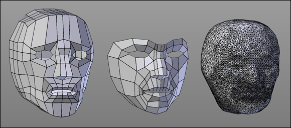
Figure 5-1: From left to right, box modeling, point-for-point modeling, and sculpting a simple human head.
Adding background images in the 3D View
When working with meshes or any other type of 3D object in Blender, reference images are often helpful for getting proper proportions and scale. If you have a separate monitor, you can choose to display your references there. However, you can use a reference more directly by loading an image into the background of the 3D View. To do so, go to the 3D View's Properties region (N) and look for the Background Images panel. Left-click the check box next to this heading and expand the panel by left-clicking the triangle to its left. You see an Add Image button. Left-click the Add Image button, and you get a panel for managing a background image. By default, your image (after you choose it) displays on all orthographic views in the 3D View. You can narrow this scope by using the Axis drop-down menu. For example, if you're modeling a person's face and have a profile photograph, then showing that background image in the front or top views isn’t useful, so you can use the Axis drop-down menu to just display the photo when you're looking from the right or left side view.
To pick an image for displaying in the 3D View, left-click the triangular icon to the left of the text that reads Not Set. Left-clicking that icon reveals an image datablock. Left-click the Open button, and Blender provides you with a File Browser for picking an image on your hard drive. When it's loaded, you can adjust the transparency, size, and positioning of your image. From here, you can continue to work, or you can add more images to display from other orthographic angles in the 3D View. People who model faces like to split the 3D View vertically, showing the front view in one 3D View and the right or left side view on the other. With reference photos of the same size set to display from the proper axis, it makes the process of modeling very speedy.
Working with Loops and Rings
Regardless of whether you're box modeling or point-for-point modeling, understanding the concepts of loops and rings definitely makes your life as a modeler a lot less crazy.
Understanding edge loops and face loops
Generally speaking, an edge loop is a series of edges that connect to form a path where the first and last edges connect to each other — well, that’s the ideal case anyway. I like to call this kind of closed edge loop a “good” edge loop.
Of course, then you probably want to know what a “bad” edge loop is. Well, you can have a path of edges that don't connect at the beginning and end of the loop, but calling these loops bad isn't really accurate. It's better to refer to edge loops that stop before reconnecting with their beginning as terminating edge loops. While you generally want to avoid creating terminating edge loops in your models, you can't always avoid having them, and sometimes you actually need them for controlling how edges flow along the surface of your mesh.
To get a better understanding of the difference between closed edge loops and terminating edge loops, open Blender and add a UV sphere (Shift+A⇒Mesh⇒UV Sphere). Tab into Edit mode on the sphere and Alt+right-click one of the horizontal edges on the sphere. This step selects an edge loop that goes all the way around the sphere like the latitude lines on a globe, as shown in the left image of Figure 5-2. This loop is a closed edge loop. Press A to deselect all and now Alt+right-click a vertical edge. When you do, you select a path of vertices that terminates at the top and bottom poles, or junctions of the sphere, as shown in the right image of Figure 5-2. That's a terminating edge loop.
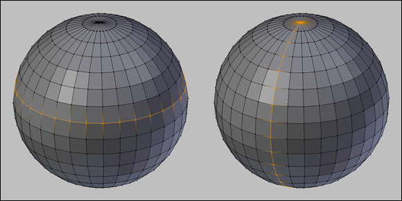
Figure 5-2: A closed edge loop (left) around a sphere and a terminating edge loop (right) on a sphere.
The vertical loop doesn't go all the way around because, technically speaking, edge loops rely on four-point poles, or a vertex that's at the junction of four edges. Imagine that following an edge loop is like driving through a city. The four-point pole is like a four-way stop, where you have the option of going left, right, or straight. Well, to properly follow the loop, you keep traveling straight. However, if you come up to a fork in the road (a three-point pole) or a five-way (or more) intersection, you can't necessarily just go straight and be sure that you're following the loop. Therefore, the loop terminates at that intersection. That's why the horizontal edge loop in Figure 5-2, which is made up entirely of four-point poles, connects to itself, whereas the vertical loop stops at the top and bottom of the sphere, where all the edges converge to a single junction.
In addition to edge loops, you can also have face loops. A face loop consists of the faces between two parallel edge loops. Figure 5-3 shows horizontal and vertical face loops on a UV sphere. In Blender, you can select face loops when you’re in Face Select mode (in Edit mode, press Ctrl+Tab⇒Faces) the same way you select edge loops in Vertex Select or Edge Select modes: Alt+right-click a face in the direction of the loop you'd like to select. For example, going back the UV sphere, to select a horizontal face loop, Alt+right-click the left or right side of one of the faces in that loop. To select a vertical face loop, Alt+right-click the top or bottom of the face.
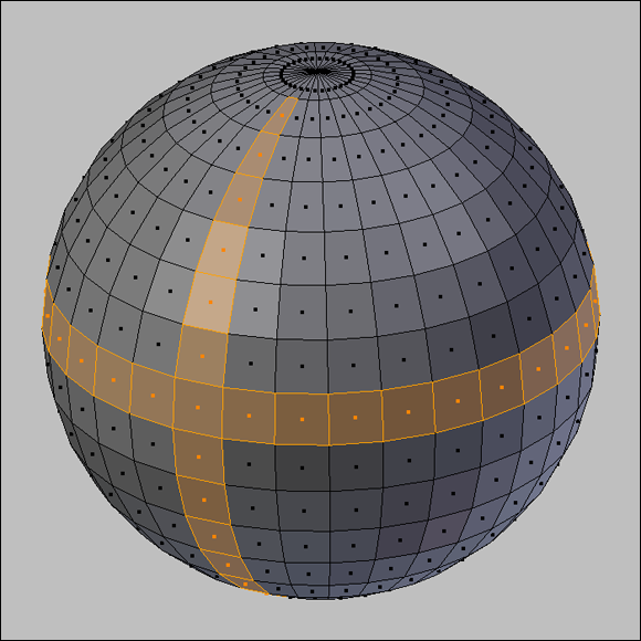
Figure 5-3: Some face loops selected on a sphere.
 In some Linux window managers, the Alt key manipulates windows, which supersedes Blender's control of it and prevents you from doing a loop select. Most window managers allow you to remap that ability to another key (like the Super or Windows key). However, if you use a window manager that doesn't offer that remapping ability, or you just don't feel like remapping that key, you can still select loops by using Shift+Alt+right-click. This key combination is actually for selecting multiple loops, but if you have no geometry (vertices, edges, or faces) selected, it behaves just like Alt+right-click.
Selecting edge rings
Say that instead of wanting to select an edge loop or a face loop, you’d like to select just the edges that bridge between two parallel edge loops, as shown in Figure 5-4. These edges form an edge ring. You can only select edge rings from Edge Select mode (in Edit mode, press Ctrl+Tab⇒Edges). When you're in Edge Select mode, you can select an edge ring by using Ctrl+Alt+right-click. Trying to use this hotkey sequence in Vertex Select or Face Select mode just selects a face loop.
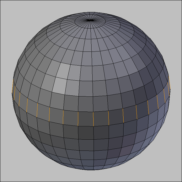
Figure 5-4: An edge ring selected on a UV sphere.
Being able to use rings and loops for selecting groups of vertices in an orderly fashion can be a huge benefit and timesaver for modeling. More importantly, when creating organic models like humans or faces, using edge loops effectively to control your topology makes the life of a character rigger and animator a lot more pleasant. (You can find out more on this topic in the sidebar “The importance of good topology,” later in this chapter.)
Creating new loops
The ability to select loops and rings is nice, but the ability to create new loops is even more helpful when you want to add detail to a model. You can detail with what's called a loop cut. When in Edit mode, you can find a button for this operator in the Tool Shelf (Tools⇒Add⇒Loop Cut and Slide). Alternatively, you can simply press Ctrl+R to access the loop cut operation directly. Regardless of how you choose to make a loop cut, when you run your mouse cursor over your model, a pink/purple line is drawn on the mesh, indicating where you might want to add your edge loop. After you decide where you want to cut, left-click to confirm (right-click cancels the whole operation). Doing so creates the edge loop and automatically enables the edge slide function on that loop. With edge slide, you can move your mouse around, and your loop travels along the surface of the mesh between its neighboring loops, allowing you to place it precisely where you want it to go when you left-click. If you ever want to use edge slide without creating a new loop, select the edge loop (or portion of an edge loop) that you want to slide and press Ctrl+E⇒Edge Slide, or use the even faster hotkey sequence G⇒G.
If you want your new loop cut to sit at the exact midpoint between its neighboring loops, right-click after the loop cut operator drops you into edge slide.
When doing a loop cut, you can actually do multiple parallel loop cuts at the same time. When you activate the loop cut operator (Ctrl+R), scroll your mouse wheel, and you'll be able to add multiple loops all at the same time. If you don’t have a scroll wheel on your mouse or you simply prefer to use your keyboard, you can adjust the number of loops in your cut by pressing Page Up and Page Down.
Cutting edges with the Knife
You can make cuts other than loop cuts. This feature is accessible with the Knife, by pressing K. The Knife is one of Blender's modal tools, meaning that once you press K, you're in a Knife mini-mode. With the Knife activated, have a look in the header region of the 3D View and notice the helpful tips. By default it should say the following:
LMB: define cut lines, Return/Spacebar: confirm, Esc or RMB: cancel, E: new cut, Ctrl: midpoint snap (OFF), Shift: ignore snap (OFF), C: angle constrain (OFF), Z: cut through (OFF)
This handy text in the header region both describes how to use the Knife as well as its current settings. To sum up:
· LMB: By left-clicking and dragging your mouse cursor in the 3D View, you can draw across the edges you want to cut. If you just left-click and release without dragging, you can define locations for new vertices in your mesh and the Knife automatically generates the edges between them.
 While you're making cuts, watch the red and green squares that appear along your cut line. These represent the vertices that the Knife will create once you confirm:
· Red squares are vertices that will definitely be created.
· Green squares are a pre-visualization of these new vertex locations.
They only show when you're in the middle of a specific cut. There's more on the green squares in the next set of bullets that cover snapping.
· Return/Spacebar: When you finish cutting with the Knife, press Enter or Spacebar to confirm your cuts (the latter is faster because your hand is already closer to Spacebar than Enter).
· Esc/RMB: To quit the Knife mini-mode without performing any cuts at all, either right-click or press Esc.
· E: You can perform multiple separate cuts while in the Knife mini-mode. Press E and you can start a new cut anywhere else on your current mesh.
· Ctrl: If you hold Ctrl while making your cuts, you're telling the Knife that you want new vertices to be placed at the midpoint of any edge your cut line crosses. If you're drawing straight cut lines with the left-click and release method, you can see the planned location of your new midpoint vertices as green squares.
· Shift: By default, Blender snaps the Knife to an edge if your mouse cursor is near it. However, there are occasions when you need to precisely place a new vertex near an edge, but not directly on it. In those cases, the default snapping behavior can be particularly frustrating. If you hold Shift while using the Knife, the default snapping behavior is temporarily disabled.
· C: Occasionally, you need to make a cut that's perfectly horizontal, vertical, or at a 45° angle (relative to the view axis). Press (and release) C to toggle the Knife's ability to constrain your cuts to these axes.
Try to avoid holding down C for the angle constrain feature, otherwise you may notice that your cut line jitters erratically. This is because the angle constrain feature is conflicting with snapping.
· Z: In some instances, you may want the Knife to cut through both sides of a mesh with the same cut line (for example, if you're modeling a four-post bed and you want to add a cut at the same height on all four posts). If you press Z while in the Knife mini-mode, you toggle the Knife's ability to perform this kind of cut through the mesh.
 The Knife's cut through feature works regardless of whether you can actually see the other side of your mesh (such as when in wireframe viewport shading or when you have Limit Selection to Visible enabled). For this reason, it's always a good idea to check the other side of your mesh after doing a cut to make sure you get your intended results.
A nice thing about working with the Knife is that you have full control over navigating within your scene while in the Knife mini-mode. You can pan, orbit, and zoom to your heart's content and place your cuts exactly where you want them.
Simplifying Your Life as a Modeler with Modifiers
Working with meshes can get complicated when you have complex models consisting of lots and lots of vertices. Keeping track of these vertices and making changes to your model can quickly become a daunting and tedious task, even with well-organized topology. You can quickly run into problems if you have a symmetrical model where the left side is supposed to be identical to the right, or if you need more vertices to make your model appear smoother. In these times, you really want the computer to take on some of this tedious additional work so that you can focus on the creative parts.
Fortunately, Blender actually has a feature, called modifiers, that helps tackle the monotony. Despite their rather generic-sounding name, modifiers are an extremely powerful way to save you time and frustration by letting the computer assume the responsibility for grunt work, such as adding smoothing vertices or making your model symmetric. Another benefit of modifiers is that they're nondestructive, meaning that you can freely add and remove modifiers to and from your object. As long as you don't apply the modifier, it won't actually make any permanent changes to the object itself. You can always return to the original, unmodified mesh.
You can access modifiers for your mesh in the Modifiers section of the Properties editor (its button has an icon of a blue wrench). Left-click the Add Modifier button to see a list of the modifiers that are available. Figure 5-5 shows the Modifiers section with the list of available modifiers for meshes.
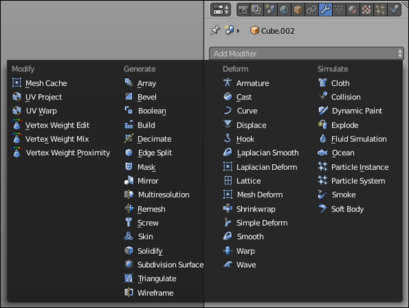
Figure 5-5: All the modifiers you can use on mesh objects.
Because of space constraints, I can't give an extensive description on every modifier in the list, but I give a brief description of each later in this section. That said, all Blender's modifiers share some of the same controls between them. Figure 5-6 shows the Modifiers section with two modifiers added, Array and Bevel.
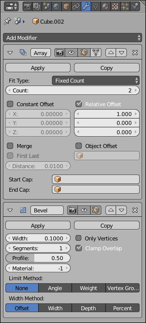
Figure 5-6: The Array and Bevel modifiers in Modifier Properties.
The first thing to notice is that the modifiers are stacked one below the other. This stacking is by design. What's more, the order in which the modifiers appear in the stack is important because one modifier feeds into the next one. So the second modifier — Bevel, in this case — doesn't operate on the original mesh data. Bevel actually operates on the new mesh data provided by the first modifier, Array, in this example.
The stacking order for modifiers is a little bit counter-intuitive if you think about it in terms of layers, where one builds on top of another. Blender's modifier stack doesn’t work like that. Instead, you’re better off thinking of Blender's modifier stack as a snowball rolling down a hill. Each modifier you hit on the way down the hill adds something or changes something about your snowball, modifying it more and more as it comes to the base of the hill. The topmost modifier is the first modifier and operates on the original mesh data. The modifier immediately below it works on the data that comes from the first modifier, and so on down the line.
In the preceding example, the object is first made into an array. Then the mesh that is created by the Array modifier has its edges beveled so that they're not as sharp-cornered. You can change the stacking order by using the up/down arrow buttons on the right side of each modifier block. Left-clicking the up arrow raises a modifier in the stack (bringing it closer to being first), whereas the down arrow lowers it. You can left-click the X at the top right of any block to remove the modifier altogether. The downward triangle that's to the left of each modifier's name collapses and expands that modifier block when you left-click it. Collapsing the modifier block is useful for hiding a modifier's controls after you've decided upon the settings you want to use.
Between the modifier name field and the stacking order buttons are three or four additional buttons, depending on whether your selected object is in Edit mode. From left to right, the first three buttons control whether the modifier is enabled for rendering (camera icon), viewing in Object mode (eye icon), and viewing in Edit mode (editing cube icon).
You may be wondering why you’d ever want to disable a modifier after you've added it to the stack, instead of just removing it and adding it back in later. The main reason is that many modifiers have an extensive set of options available to them. You may want to see how your object renders with and without the modifier to decide whether you want to use it. You may want to edit your original mesh without seeing any of the changes made by the modifier. If you have a slow computer (or if you want your fast computer to be as responsive as possible), you want to have the modifier enabled only when rendering so that you can still work effectively without your computer choking on all the data coming from Blender.
Some modifiers, like Array, have an additional fourth button with an inverted triangle icon at the end of the button block. Its tooltip says that enabling this button will Adjust Edit Cage to Modifier Result. The edit cage is the input mesh, prior to any influence by the modifier. Enabling this button means that not only are the effects of the modifier visible in Edit mode, but you can also select and perform limited changes to the geometry created by the modifier.
Only two more buttons are common among all modifiers: the Apply and Copy buttons. Left-clicking the Apply button takes the changes made by the modifier and directly applies them to the original object. Applying actually creates the additional vertices and edges in the original mesh to make the mesh match the results produced by the modifier and then removes the modifier from the stack. While modifiers are nondestructive, meaning that they don't permanently change the original object, the Apply button is the one exception.
The Apply button works only if the object you're working on is in Object mode.
The Copy button creates a duplicate version of the modifier and adds it to the stack after the modifier you're duplicating. You probably won't be using this function very often, but it's useful when you need to double up a modifier, such as if you want to use one Subdivision Surface modifier with simple subdivisions to get more raw geometry and then use a second Subdivision Surface modifier to smooth or curve that geometry.
Modify modifiers
The first column of modifiers is somewhat of a hodge-podge; it's a bit of a dumping ground for modifiers that don't really fit anywhere else. The main common feature across these modifiers is that they affect vertices or vertex data. With the possible exception of the UV Project modifier, these modifiers are more commonly used in the complex scenes that a more advanced Blenderhead may have, so don't sweat too much if you don't see an immediate use case for them. The six modifiers in this column are
· Mesh Cache: This modifier replaces all of your mesh's geometry with new data from a mesh cache file. In large scale animated productions, it's common practice to take completed character animation (set up with a complex animation rig; see Chapter 11) and “bake” it into the vertex data before moving on to lighting and rendering. This modifier facilitates that workflow.
· UV Project: Think of the UV Project modifier as a video projector or a slide projector. It produces a similar effect to an object-mapped texture (see Chapter 8), though it's more flexible and, unlike object mapping, is usable in Blender's Cycles renderer (Chapters 7, 8, and 9 give a lot more detail on Cycles and how to use it).
· UV Warp: The UV Warp modifier is similar to the UV Project modifier, as it modifies your mesh's UV coordinates (see Chapter 8 for UV coordinates). The difference, however, is that the UV Warp modifier gives you the ability to rig and deform your UV coordinates for animation much like you would rig the vertex data of your mesh.
· Vertex Weight Edit/Mix/Proximity: As their names imply, these three modifiers manipulate vertex weights. Vertices in a mesh can belong to one or more vertex groups (I cover vertex groups in detail in Chapter 11). For each vertex, you can define a weight (a numeric value from 0.0 to 1.0) defining how much a vertex belongs to a particular group. These modifiers give you more control over those vertex weights. (They're particularly useful in complex animation rigs.)
Generate modifiers
The Generate category of modifiers contains the most commonly used modifiers in a Blender modeler's arsenal. They're a procedural means of adding — and in some cases removing — geometry in your mesh. And because they're modifiers, they can be stacked to produce pretty complex models from simple base objects . . . and then the parameters in that stack of modifiers can be animated! The list of available modifiers in this category is extensive. The following is a quick run-through of each of them:
· Array: The basic functionality creates one or more copies of your base mesh and places them based on an offset value you define. The Array modifier is one of my favorites; I go into it in more detail later in this chapter.
· Bevel: Nothing in the real world has perfectly sharp corners or edges. They're always slightly rounded, even if a little bit. The Bevel modifier helps you add that little touch of realism to your object.
· Boolean: The Boolean modifier allows you to mix two meshes together, adding, subtracting, or intersecting a separate mesh with your current one.
This modifier can generate some pretty ugly topology.
· Build: With this relatively simple modifier, the individual faces in your mesh appear over time. You can also reverse the effect to have your mesh slowly disappear over time, one face at a time.
· Decimate: Occasionally you will need to reduce the amount of geometry in your model (for example, your model might need to be used in a video game, a segment of the 3D computer graphics field renowned for having tight geometry budgets for each object). The Decimate modifier can give you a head start in reducing your model's geometry.
· Edge Split: When modeling, you can define whether a face in your mesh gets rendered as smooth or flat. More often than not, you'll want it to appear smooth. However, in doing this, you lose definition at hard edges in your model. You could add a Bevel modifier to fix this, but if you're trying to keep your vertex count down, that may produce more geometry than you want. The Edge Split modifier lets you keep sharp edges without adding a significant amount of geometry.
· Mask: The Mask modifier gives you the ability to define some vertices in your mesh as being hidden from view, depending on either their membership in a vertex group or their relation to an armature bone.
· Mirror: This modifier duplicates the geometry in your base mesh and flips it along one or more of your object's local axes. It's extremely useful when you're modeling anything that's symmetric in nature. I cover the Mirror modifier in more detail later in this chapter.
· Multiresolution: This modifier subdivides your mesh by the same rules used in the Subdivision Surface modifier (covered later in this section). The difference is that Multiresolution can be applied multiple times and you can use Sculpt mode to freely edit the generated vertices at any of the subdivision levels you generate. I cover the Multiresolution modifier in more detail later in this chapter when discussing sculpting in Blender.
· Remesh: There are times when the topology of your mesh just is not salvageable (such as when doing heavy sculpting or using booleans). The Remesh modifier can give you a more reasonable starting place for a mesh with cleaner topology (or at least evenly spaced faces for more detailed sculpting).
· Screw: The Screw modifier duplicates the geometry of your mesh one or more times and rotates those duplicates about one of its local axes. You can use this to create helix shapes (like springs and, well, screws) as well as a way to generate an object from a simple profile, similar to a “lathe” operator in other software. There's a tutorial that covers this technique on this book's website (www.blenderbasics.com).
· Skin: Using the Skin modifier, the vertices and edges in your mesh are given a “skin”. That is, new geometry is generated around them, based on a radius you define in Edit mode. In a way, it's similar to increasing the Bevel value on a curve object as described in Chapter 6. This modifier gives you a fantastic way to generate base meshes for sculpting or sprawling organic shapes like vines and other vegetation. As an additional bonus, this modifier can also generate an armature object with properly defined vertex weights so you more easily deform and animate your mesh.
· Solidify: Polygon faces in 3D graphics are infinitely thin. So if you try to look at them from certain angles, they simply aren't visible. Of course, that doesn't match the real world. In meatspace, everything has a little bit of thickness. The Solidify modifier is a quick and easy way to add that thickness to any mesh.
· Subdivision Surface: This modifier is one of the most useful (and frequently used) in Blender. Simply put, the Subdivision Surface modifier adds vertices to your mesh by subdividing each edge and face. (I cover it in more detail later in this chapter.) This behavior allows for more detail and smoother surfaces on your mesh. It's especially useful for organic models like plants and animals.
· Triangulate: Some game engines (the code “under the hood in a video game”) require that all meshes consist of only triangular faces. Quads and ngons aren't allowed. Using this modifier, you can get an idea of what your model looks like with all triangular faces, without prematurely committing to that topology.
· Wireframe: The Wireframe modifier is somewhat like the Skin modifier in that it creates geometry around each of the edges in your mesh. The controls and purpose of this modifier are different, however. Rather than being used to generate a base mesh as a starting point, the Wireframe modifier is most useful in generating renderable wireframes of your mesh so you can cleanly show its topology to your peers.
Deform modifiers
In computer graphics, the word deform doesn't carry any kind of negative connotation. When something is deformed in computer graphics, it means that sub-components of that thing have been moved. In the case of 3D computer graphics, those sub-components are the vertices, edges, and faces that make up your mesh's geometry. Knowing that, it isn't hard to figure out that the modifiers in the Deform category are used to change the position of geometry in your mesh. Unlike the Generate modifiers, none of these modifiers add or remove geometry. They just move that geometry around, based on either a set of rules or external controls. While these modifiers can be used for modeling, they're more frequently employed as tools for creating animation rigs (see Chapter 11). The following is a brief description of each Deform modifier:
· Armature: When it comes to animation rigs, the Armature modifier is the tool of choice for starting. This modifier is the mechanism that binds your mesh to an armature object and allows the bones of that armature to control the geometry in that mesh.
· Cast: Simply put, this modifier pushes the geometry in your mesh to match one of three primitive forms: a sphere, a cylinder, or a cube.
· Curve: The Curve modifier is similar to the Armature modifier, but it uses as curve object instead of the bones of an armature object to define your mesh's deformation. This is useful if you're rigging something that has a naturally curved change in shape, like a cartoon fish.
· Displace: Using a grayscale image often referred to as a height map (lighter pixels represent high areas, darker pixels represent low areas), the Displace modifier can offset individual vertices from their initial location. This can be a handy way to add bumpy detail or even model some terrain.
· Hook: This modifier binds one or more vertices in your mesh to an external object. Hooks are useful for bulging or stretching part of your mesh. They're also useful for controlling curve objects. Chapter 11 has a whole section dedicated to hooks and the Hook modifier.
· Laplacian Smooth: Sometimes you have a model with a lot of hard edges and creases, but you need a version that's generally much smoother. The Laplacian Smooth modifier is a great tool for addressing that issue. It can be particularly useful for cleaning up meshes from 3D scanners or the Remesh modifier.
· Laplacian Deform: The deformation capabilities of hooks and armatures are very powerful, but they can occasionally “fuzz out” the details in your model or create excessive distortion that doesn't preserve the volume of your base mesh. The Laplacian Deform modifier helps to alleviate that problem computationally (as opposed to the more manual methods using lattices or the Mesh Deform modifier).
· Lattice: Lattices are special objects in Blender that consist of a boxy network of interconnected control points. When a mesh has a Lattice modifier, you can use one of these lattice objects to perform broad deformations. In cartoony character animation, lattices can be particularly useful for giving characters convincing squash and stretch effects.
· Mesh Deform: In its simplest explanation, the Mesh Deform modifier allows you to use a regular mesh to achieve some of the same deformation effects that a lattice can give you. There are trade-offs, of course, but that gets into a much more advanced discussion on rigging.
· Shrinkwrap: Using the Shrinkwrap modifier, you can snap the vertices of your current mesh to the surface of another mesh, as if you wrapped that other mesh in shrinkwrap. As an example, if you're doing a cartoon-style animation that involves the cliché of a bulge of water traveling along a water hose, you can achieve that effect with this modifier. Additionally, some modelers use this modifier to help get a starting point when they retopo a sculpt.
· Simple Deform: This modifier gives you the ability to twist, bend, taper, or stretch your mesh relative to its local Z-axis.
· Smooth: The Smooth modifier does essentially the same thing as the Laplacian Smooth modifier, but it uses a different algorithm. Generally speaking, it's faster than the Laplacian Smooth modifier, but on complex meshes, the result usually is less appealing. It tends to “melt” the shape of the object a bit, losing volume from all sides, like a lollipop.
· Warp: Using the location, orientation, and scale of any two reference objects, you can use the Warp modifier to distort your mesh, stretching its vertices from the origin of one object to the origin of the other.
If you're familiar with proportional editing, as described in Chapter 4, think of this modifier as a way to give you that capability without directly selecting any vertices.
· Wave: If you apply the Wave modifier to a somewhat heavily subdivided plane, it gives an appearance similar to dropping a pebble in a still pond. Of course, you don't have to use a subdivided plane, the Wave modifier works on any mesh. Fair warning: if your mesh only has a few vertices in it, you will not see the wave effect. It will just appear like your whole mesh is moving up and down as a single unit.
Simulate modifiers
The last column of modifiers contains the Simulate modifiers. With a couple of exceptions (Explode and Ocean), you almost never add these modifiers from Modifier Properties. They get automatically added to your mesh when you add a particle system from Particle Properties or add a physics simulation from Physics Properties. It's an advanced topic, but Chapter 13 has a bit more detail on using particles and physics simulations from within Blender.
Doing half the work (and still looking good!) with the Mirror modifier
When I was first learning how to draw the human face, I used to have all sorts of problems because I'd draw half the face and then realize that I still needed to do nearly the exact same thing all over again on the other side of the face. I found it tedious and difficult to try to match the first half of my drawing. Without fail, the first couple of hundred times I did it, something would always be off. An eye would be too large, an ear would be too high, and so on. I'm not embarrassed to say that it actually took me quite a long time to get drawings that didn't look like Sloth from The Goonies. (Some of my coworkers might argue that some of my drawings still look that way!)
Fortunately, as a 3D computer artist, you don't have to go through all that trial and error. You can have the computer do the work for you. In Blender, you use the Mirror modifier (Modifiers Properties⇒Add Modifier⇒Mirror). Figure 5-7 shows the buttons and options available for this modifier.

Figure 5-7: The Mirror modifier.
The Mirror modifier basically makes a copy of all the mesh data in your object and flips it along its local X-, Y-, or Z-axis, or any combination of those axes. The Mirror modifier also has the cool feature of merging vertices along the center seam of the object so that it looks like one unified piece. By changing the Merge Limit value, you can adjust how close vertices have to be to this seam in order to be merged.
The X, Y, and Z check boxes dictate which axis or axes your object is mirrored along. For most situations, the default setting of just the local X-axis is all you really need. I nearly always enable the Clipping check box. This option takes the vertices that have been merged — as dictated by the Merge Limit value — and locks them to the plane that your mesh is being mirrored across. That is, if you're mirroring along the X-axis, then any vertices on the YZ plane are constrained to remain on that plane. This feature is great when you're working on vehicles or characters where you don't want to accidentally tear a hole along the center of your model while you're tweaking its shape with the proportional editing (O) enabled. Of course, if you do have to pull a vertex away from the center line, you can temporarily disable this check box.
The next check box is labeled Vertex Groups. As mentioned in the previous section, you can assign vertices in a mesh to arbitrary groups, known as vertex groups, which you can designate in Mesh Properties, as shown in Figure 5-8.
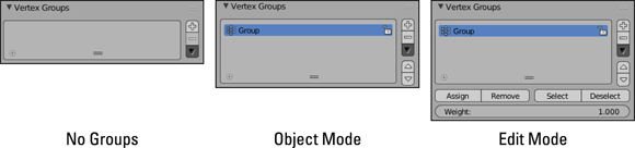
Figure 5-8: Vertex groups are created with the Mesh Properties.
Chapter 11 covers the actual process of creating vertex groups and assigning individual vertices to a group. However, the most basic way uses the following steps:
1. Left-click the plus (+) icon to the right of the list of vertex groups in Mesh Properties.
A new vertex group named Group appears in the list box.
2. From Edit mode, select some vertices in your mesh and press the Assign button below the vertex group list.
You now have a vertex group with a set of vertices assigned to it.
Here's how the Vertex Groups check box in the Mirror modifier works: Say that you've selected some vertices and assigned them to a group named Group.R, indicating that it's the group for some vertices on the right-hand side. And say that you've also created another group called Group.L for the corresponding vertices on the left-hand side, but because you have not yet applied the Mirror modifier, you have no way to assign vertices to this group. Well, if you have the Vertex Groups check box enabled, the generated vertices on the left side that correspond with the Group.R vertices are automatically assigned to Group.L. You don't even have to apply the modifier to get this result! This effect propagates to other modifiers that are based on vertex group names, such as the Armature modifier.
Referring back to Figure 5-7, the U and V check boxes under the label of Textures in the Mirror modifier do the same kind of thing that the Vertex Groups check box does, but they refer to texture coordinates, or UV coordinates. You can find out about UV coordinates in Chapter 8. The simplest explanation, though, is that UV coordinates allow you to take a flat image and map it to a three-dimensional surface. Enable these buttons on the modifier to mirror the texture coordinates in the UV/Image Editor and to possibly cut your texture unwrapping time in half. To see the results of what these buttons do when you have a texture loaded and your model unwrapped, bring up the Properties region in the UV/Image Editor (View⇒Properties or N) and left-click the Modified check box. Hooray for nondestructive modifiers!
The last option in the Mirror modifier is the object datablock field at the bottom labeled Mirror Object. By default, the Mirror modifier uses the object's origin as the basis for what to mirror. However, by clicking in this field and choosing the name of any other object in your scene, you can use that object's origin as the point to mirror across. With the Mirror Object feature, you can use an Empty (or any other object) as a kind of dynamic origin. With a dynamic origin, you're able to do fun things like animate a cartoon character splitting in half to get around an obstacle (literally!) and joining back together on the other side.
Blender's text fields have integrated search, which means that you can type the first few letters of an object's name and if the name is unique, Blender displays a list of objects in your scene that match what you've typed.
Smoothing things out with the Subdivision Surface modifier
Another commonly used modifier, especially for organic models, is the Subdivision Surface modifier. Old-school Blender users may refer to the Subdivision Surface modifier as the Subsurf modifier. If you have a background in another 3D modeling program, you may know subdivision surfaces as sub-ds or subdivs.
If you're not familiar with subdivision surfaces, the concept goes something like this: Blender takes the faces on a given mesh and subdivides them with a number of cuts that you arbitrarily decide upon (usually one to three cuts, or levels of subdivision). Now, when the faces are subdivided, Blender moves the edges of these faces closer together, trying to get a smooth transition from one face to the next. The end effect is that a cube with a Subdivision Surface modifier begins looking more and more like a ball with each additional level of subdivision, as shown in Figure 5-9.
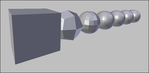
Figure 5-9: A cube with increasing levels of subdivision from 1 to 6.
Now, the really cool thing about subdivision surfaces is that because they're implemented as a modifier, you get the smooth benefit of additional geometry without the headache of actually having to edit all those extra vertices. In the preceding cube example, even at a subdivision level of 6, if you tab into Edit mode, you control that form with just the eight vertices that make up the original cube. This ability to control a lot of vertices with a relative few is a very powerful way of working, and nearly all high-end 3D animations use subdivision surfaces for just this reason. You have the smooth organic curves of dense geometry with the much more manageable control of a less dense, or low poly mesh, referred to as a cage.
For a better idea of the kind of results you can get with the Subdivision Surface modifier, break out Suzanne and apply it to her with the following steps:
1. Add a Monkey mesh (Shift+A⇒Mesh⇒Monkey).
Ooh! Ooh! Ooh!
2. Set smooth rendering on the monkey (Tool Shelf⇒Tools tab⇒Shading⇒Smooth).
At this point, Suzanne is pretty standard. She looks smoother than the faceted look she had when first added, but she's still blocky looking.
3. Add a Subdivision Surface modifier to the monkey (Modifier Properties⇒Add Modifier⇒Subdivision Surface or use the Ctrl+1 hotkey combo).
Now that's Suzanne! Instantly, she looks a lot more natural and organic, even despite her inherently cartoony proportions. Feel free to increase the View number in the Subdivision Surface modifier to see how much smoother Suzanne can be. I caution you not to go too crazy, though. Setting subdivisions above 3 might choke your computer a bit if it's too slow.
4. Tab into Edit mode and notice that the original mesh serves as the control cage for the subdivided mesh.
Editing the cage with grab (G), rotate (R), scale (S), and extrude (E) directly influences the appearance of the modified mesh within the cage.
Figure 5-10 shows the results of each step.
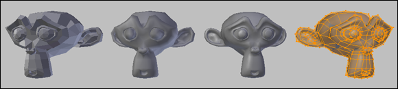
Figure 5-10: Adding the Subdivision Surface modifier to Suzanne.
As powerful as the Subdivision Surface modifier is, only a limited number of options come with it in the modifier stack. Figure 5-11 shows the Subdivision Surface modifier block as it appears in Modifier Properties. The first option is a choice between Catmull-Clark subdivision or Simple subdivision. The former is the default, subdividing and smoothing your mesh as expected. The latter works more like doing W ⇒ Subdivide multiple times while in Edit mode. It gives you more vertices in your meshes, but not the same kind of organic smoothness that the Catmull-Clark method provides. The simple subdivision method is good for some situations, though, so it's nice that the option is available.
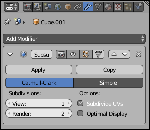
Figure 5-11: The Subdivision Surface modifier.
The next set of values, labeled Subdivisions, allow you to set the level of subdivision that you see on your model. The first value, View, dictates the number of subdivisions your mesh uses in the 3D View. You can set View to a whole number from 1 to 6. Because I like to keep my 3D View fast and responsive, I tend to keep this number down at 1. Occasionally, I push it up to 2 or 3 to get a quick idea of what it might look like in the final output, but I always bring it back down to 1 or 0.
Beneath View is a similar value input labeled Render. When you create the final output of your scene or animation, Blender uses this level of subdivision for your model, regardless of which level you set for the 3D View. The Render value has the same range that View does, but typically it’s set to a higher value because you usually want smoother, higher-quality models in your final render. Don't go too crazy with setting this value. On most of my work, which can get pretty detailed, I rarely ever use a setting higher than 3.
Use the Subdivide UVs check box for texturing. Like the U and V check boxes in the Mirror modifier, enabling this option adds the additional geometry to your UV map without requiring you to apply the modifier. Again, this timesaver can be quite helpful when you're setting up your model for texturing. It's such a consistently useful feature that this check box is enabled by default. Also, like the U and V options in the Mirror modifier, you can see the results of the Subdivide UVs check box by enabling the Modified check box in the UV/Image Editor.
The Optimal Display check box is something I typically like to leave turned on all the time. Optimal Display hides the extra edges that are created by the modifier when you view the model in wireframe view. On a complex scene, hiding the edges can definitely help you make sense of things when working in wireframe. Figure 5-12 shows the difference Optimal Display makes on a Suzanne model with three levels of subdivision.
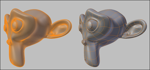
Figure 5-12: Using Optimal Display on a mesh with three levels of subdivision.
When working with the Subdivision Surface modifier, I typically like to have the Optimal Display option enabled, along with the Adjust Edit Cage to Modifier Result button at the top of the Subdivision Surface modifier panel. Everyone's different, though, so play with it on your own and see what works best for you.
Using the power of Arrays
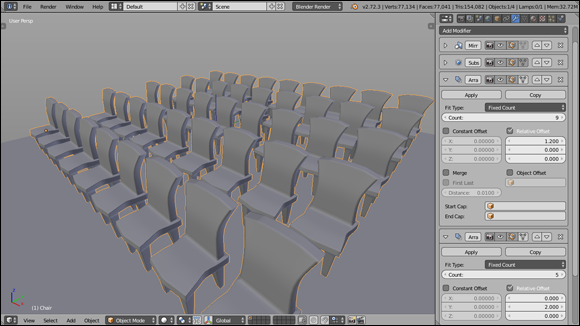
One of the coolest and most-fun-to-play-with modifiers in Blender is the Array modifier. In its simplest application, this modifier duplicates the mesh a specified number of times and places those duplicates in line, evenly spaced apart. Have a model of a chair and need to put lines of chairs in a room to make it look like a meeting hall? Using a couple of Array modifiers together is a great way to do just that! Figure 5-13 is a screenshot of Blender being used to create that sort of scene.

Figure 5-13: Filling a room with chairs by using the Array modifier.
You're not limited to using just one Array modifier on your object. I achieved the effect in Figure 5-13 by using two Array modifiers stacked together, one for the first row of chairs going across the room and the second to create multiple copies of that first row. Stacking multiple arrays is an excellent way to build a complex scene with just one object.
Blender's Array modifier is loaded with all kinds of cool functions that you can use in lots of interesting ways. Some ways facilitate a desire to be lazy by making the computer do as much of the repetitive, tedious tasks as possible. (For example, you can use the Array modifier to model a staircase or a chain-link fence or a wall of bricks.) However, you can also use the Array modifier to do some really incredible abstract animations or specialized tentacles or even rows of dancing robots!
The bulk of the power in the Array modifier lies in how it handles offsets, or the distances apart that the duplicates are set relative to one another. As shown in Figure 5-14, the Array modifier offers three different sorts of offsets, all of which you can use in combination with one another by enabling their check boxes:
· Constant Offset: This offset adds a fixed distance to each duplicated object in the array. So setting the X value beneath this check box to -5.0 shifts each of the duplicates five units in the negative X direction. The same behavior happens in the Y- and Z-axes when you set the values for those offsets as well.
· Relative Offset: Think of the Relative Offset as a multiplication factor, based on the width, height, and depth of the object. So no matter how large or small your object is, if you set the Z value to 1.0, for example, each duplicated object in the array is stacked directly on top of the one below it. This type of offset is the one that's used by default when you first add the Array modifier.
· Object Offset: The Object Offset is my personal favorite offset because of its incredible versatility. It takes the position of any object you pick in the Object field — I prefer to use Empties for this purpose — and uses its relative distance from the mesh you added to Array as the offset. But that's just the start of it! Using this offset also takes into account the rotation and scale of the object you choose. So if you have an Empty that's one unit away from your object, scaled to twice its original size, and rotated 15 degrees on the Y-axis, each subsequent duplicate is scaled twice as large as the previous one and rotated an additional 15 degrees. Now you can make a spiral staircase like the one in Figure 5-15. And if you feel inclined to create an animation of a staircase where the stairs can be collapsed into each other and hidden, it's a simple as animating the offset object!
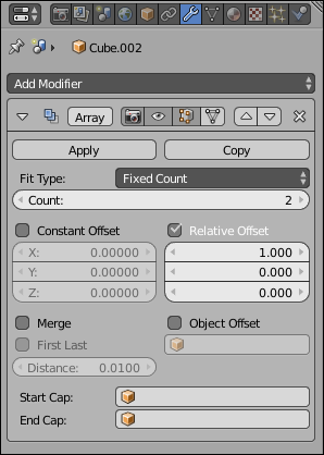
Figure 5-14: The Array modifier.
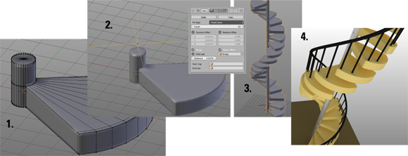
Figure 5-15: (1) Model the step. (2) Add an Empty for Object Offset and rotate in Z. (3) Add the Array modifier. (4) Make it pretty.
You also have a lot of control over how many duplicates the Array modifier creates, thanks to the Fit Type drop-down menu at the top of the Array modifier block. By default, the Fit Type is set to Fixed Count, and you explicitly enter the number of duplicates in the Count field below it. Fixed Count isn't your only Fit Type option, however. You actually have three:
· Fixed Count: This option lets you explicitly enter the exact number of duplicates you would like to create, up to 1,000.
The maximum value of 1,000 for the Fixed Count value is what's known as a “soft maximum” in Blender. This means that if you adjust that value using the mouse, it caps out at 1,000. However, if you click in that field, you can manually type numbers much larger than 1,000. Blender will use that manually entered number.
· Fit Length: This option creates the proper count of duplicate objects to fit in the distance that you define. Bear in mind that this length isn’t exactly in whole units. It uses the local coordinate system of the object that you're making an array of, so the length you choose is multiplied by the scale of that original object, as shown in the 3D View's Properties region (N).
· Fit Curve: If you choose this option, you can choose the name of a curve object in the Object datablock field below it. When you do, Blender calculates the length of that curve and uses that as the length to fill in with duplicated objects. Using this option together with a Curve modifier is a nice quick-’n-dirty way of creating a linked metal chain.
Blender and real-world units
Older versions of Blender didn’t have any notion of real-world units. They had only a vague notion of Blender units, which you could mentally convert to any unit system available. The typical behavior was to assume that one Blender unit equaled one meter, but that wasn't a hard-and-fast rule.
This oversight has been fixed, giving Blender support for real units. Blender defaults to the old behavior of using Blender units, but Scene Properties has a panel labeled Units. If you need to explicitly use Metric (meters, centimeters, and so on) or Imperial (inches, feet, and so on) units, you can set those values here.
Another cool feature in the Array modifier is the ability to merge the vertices of one duplicate with the vertices that it’s near in another duplicate, similar to the Mirror modifier. With the Merge check box enabled and some fine adjustment to the Distance value, you can make your model look like a single unified piece, instead of being composed of individual duplicates. I've used this feature to model rope, train tracks, and stair rails, for example. The First Last check box toggles to determine whether the vertices in the last duplicated instance are allowed to merge with the nearby vertices in the first object of the array. Use merging with Object Offset, and you can create a closed loop out of your duplicates, all merged together.
Say that you're using the Array modifier to create a handrail for your spiral staircase, and you don't want the handrail to simply stop at the beginning and end. Instead, you'd like the end of the handrail to have ornamental caps. You could model something and try to place it by hand, but that process can get problematic if you have to make changes or animate the handrail in the future. (Hey, this is computer graphics. Handrails that move and are animated make complete sense!) So another way to place ornamental caps on a handrail is to use the Start Cap and End Cap fields in the Array modifier. After you model what you want the cap to look like, you can pick or type the name of that object in these fields, and Blender places it at the beginning and the end of the array, respectively. Pretty slick, huh?
Sculpting in Virtual Space
Over the years, as computers have gotten more powerful and more capable of handling dense models with millions of vertices (sometimes called high-poly meshes), computer graphics artists have wanted more and more control over the vertices in their meshes. Using a Subdivison Surface modifier is great for adding geometry to make models look more organic, but what if you're modeling a monster and you want to model a scar in his face? You have to apply the modifier to have access and control over those additional vertices. And even though the computer may be able to handle having them there, a million vertices is a lot for you to try to control and keep track of, even with all the various selection methods and the Proportional Edit Tool. Fortunately, Blender supports multiresolution meshes and Sculpt mode that allows for dynamic topology.
Multiresolution (or multires) meshes address the problem of having to apply the Subdivision Surface modifier before you can directly control the vertices that it creates. With a multires mesh, you can freely move between a level 1 subdivision and a level 6 subdivision, just like with the Subdivision Surface modifier. However, the difference is that you can directly control the vertices of the level 6 subdivision just as easily as the level 1 subdivision by using Blender's Sculpt mode. And you can see changes made in either level — to varying levels of detail, depending on the level you're looking at. (If you make a very fine detail change in level 6, it may not be readily apparent at level 1.)
Sculpting with the Multiresolution modifier
Creating a multires mesh is just like adding any other modifier to a mesh object. Figure 5-16 shows what the Multiresolution modifier block looks like.
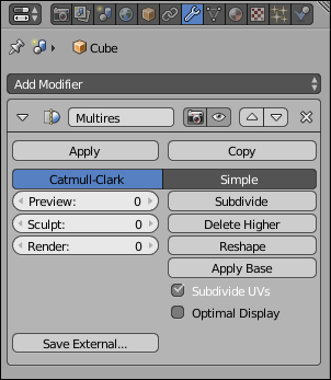
Figure 5-16: The Multiresolution modifier block.
The Multiresolution modifier is similar in appearance to the Subdivision Surface modifier. By default, the Multiresolution modifier starts with zero subdivisions on your mesh. Use the Subdivide button to increase the level of subdivision that you want to add to your mesh. Subdividing increments the values for Preview, Sculpt, and Render. Like the View and Render values in the Subdivision Surface modifier, these values control how many levels of subdivision you see in the 3D View, both while sculpting and when your model is rendered, respectively.
However, unlike with the Subdivision Surface modifier, you don't have exactly six levels of subdivision to switch between. In the Multiresolution modifier, the number can be as low as zero and as high as your computer's processor and memory can handle. And before adding a level, you have the option of choosing Catmull-Clark Subdivision or Simple Subdivision, like you can with the Subdivision Surface modifier.
The only caveat is that you can’t freely change between subdivision types on a given level with the Multiresolution modifier. Changing from Catmull-Clark to Simple (or vice versa) has an effect on all multires levels.
If you have a Subdivision Surface modifier on your mesh, I recommend applying it to your mesh or removing it from the modifier stack before adding the Multiresolution modifier. Because the Multiresolution modifier uses the same process to create subdivision levels, you really don't need to have both active at the same time.
After you have a level added, you have some additional options available. Clicking Delete Higher removes all subdivision levels greater than the level you’re currently in. So if you have five levels of subdivision and you're at level 3, clicking Delete Higher effectively kills levels 4 and 5.
Enabling the Optimal Draw check box does the same thing that the corresponding check box does in the Subdivision Surface modifier: It prevents Blender from showing subdivided edges in the 3D View. Some 3D modelers who use sculpting tools like to overlay the model's wireframe on the mesh (Object Properties⇒Display⇒Wire check box) as they work so that they can have an idea of how their topology looks. (See the sidebar "The importance of good topology" in this chapter for more information.) Without Optimal Draw enabled, the 3D View of your model can quickly get cluttered, so enabling this check box simplifies the display for you.
Now, if you try to tab into Edit mode on a multires mesh, you still see only the vertices available to you in the cage provided by the base mesh. So how do you actually edit all those additional vertices created by the Multiresolution modifier? The answer: Sculpt mode. Sculpt mode treats your mesh very much like a solid piece of clay. You have a variety of sculpt brushes that help you shape and form your mesh to look exactly how you want. You can activate Sculpt mode from the Mode menu in the 3D View's header. Alternatively, if you have the Pie Menus add-on enabled, Sculpt mode is a menu item you can choose when you press Tab. When you're in Sculpt mode, the Tools tab of the Tool Shelf (T) updates to show a whole set of options available to you for editing your mesh.
If you have a drawing tablet like the ones manufactured by Wacom, Sculpt mode takes advantage of the pressure sensitivity that a tablet offers.
When working in Sculpt mode and using the Multiresolution modifier, the general workflow is to start at low levels of subdivision to block out the rough shape of your model and then proceed to higher levels of subdivision for more detailed elements of your model. The process is very much like traditional sculpting in meatspace, as well as box modeling in the CG world. The only difference in this case is that the Multiresolution modifier allows you to freely move between high and low levels of subdivision, so you don't have to block out your whole model in a single go.
Nothing says that you're required to use the Multiresolution modifier when sculpting in Blender. In fact, Sculpt mode works just fine without any Multiresolution modifier at all.
Freeform sculpting with dynamic topology (Dyntopo)
 One of the most groundbreaking features to hit Blender's modeling community in recent years was the ability to have dynamic topology (dyntopo for short) while in Sculpt mode. Simply put, when you enable dyntopo, your sculpting brush can add or remove geometry from your mesh on the fly. Need more detail in just one part of your model? There's no need to use the Multiresolution modifier and bump up the vertex count for your whole mesh. Just enable dyntopo and that detail exactly where you need it.
To use dyntopo, you need to be in Sculpt mode. While in Sculpt mode, look at the Tools tab in the Tool Shelf (T). A panel in that tab is named, appropriately, Dyntopo. When you expand that panel, there's a large button at the top labeled Enable Dyntopo. Left-click that button and you're off to the races, sculpting with dynamic topology. Alternatively, you can also enable dyntopo with Ctrl+D while in Sculpt mode. Figure 5-17 shows the Dyntopo panel in the Tool Shelf.
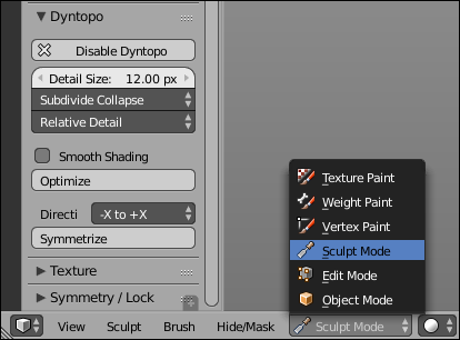
Figure 5-17: The Dyntopo panel in the Tool Shelf allows you to enable dynamic topology while in Sculpt mode.
For such a powerful feature, there are relatively few options that are specific to dyntopo. The following is a quick run-down of the options available in the Dyntopo panel:
· Detail Size: Dyntopo works by modifying edges within the area of your brush stroke. The Detail Size field defines a value that lets dyntopo decide whether a specific edge gets modified, based on its length. This value can either be in screen pixels or a percentage, depending on the detail type method that you choose (I cover detail types in this list). While sculpting, you can adjust this value with the Shift+D hotkey so you don't have to constantly return to the Tool Shelf.
· Detail Refine Method: Dyntopo can subdivide edges in your mesh and collapse them, removing additional detail. The options in this drop-down menu allow you to control which behavior you want your sculpt brush to use:
· Subdivide Edges: The Subdivide Edges option is the default. If an edge within your brush stroke is longer than the detail size, it's subdivided. This refine method is great for fine details, creases, and sharp peaks.
· Collapse Edges: When you choose the Collapse Edges option, short edges get collapsed into a single edge. In the case of dyntopo, a short edge is defined as being two-fifths () the length of the detail size. This option is great for evening out your topology and removing long skinny triangles that may render weirdly. However, the trade-off is that it also removes any fine details smaller than the detail size.
· Subdivide Collapse: Choose this option and edges within the area of your brush stroke are subdivided and collapsed, relative to the detail size. This behavior makes the Subdivide Collapse option well-suited for quickly roughing the general forms of your sculpt.
· Detail Type Method: When sculpting, it's common for artists to arbitrarily navigate around their model as they work, orbiting, panning, and zooming to get the best view of the section that they’re sculpting.
Zooming specifically presents an interesting challenge for dyntopo because sometimes you want the detail size to remain the same regardless of how much you zoom in or out from your model; other times, you want to do more detailed work as you zoom closer. The options in this drop-down menu let you choose:
· Relative Detail: This is the default setting. Choose this option to define detail size relative to the pixels on your screen. If you zoom out far enough, all of the edges in your mesh become smaller than the detail size. If you zoom in, you only subdivide smaller edges.
· Constant Detail: Choose the Constant Detail option if you want the detail size to remain the same, regardless of how much you zoom in or out from your model. With this option, detail size is defined as a percentage of a Blender unit. Additionally, the Detail Size field at the top of the Dyntopo panel gets an eyedropper button. Left-click that button to sample the geometry in your mesh. This means that you can click the eyedropper on a part of your mesh and the Detail Size field is set to match the edge lengths in that region.
· Smooth Shading: The Smooth Shading check box toggles between smooth shading and flat shading for your entire mesh while sculpting. This is mostly a personal preference, though some sculptors claim to have a more responsive 3D Viewport with Smooth Shading disabled.
· Optimize: As you sculpt with dyntopo enabled, your brush may become less responsive, with strokes lagging behind your mouse cursor as you work. If you run into that, try left-clicking the Optimize button. When you click, Blender recalculates and rebuilds the underlying data structure that dyntopo uses to speedily edit the edges on your mesh, often alleviating some sculpting performance slowdowns.
· Detail Flood Fill: The Detail Flood Fill button is only visible if you have your detail type set to Constant Detail. Assuming that you have chosen Constant Detail, you can left-click the Detail Flood Fill button to subdivide (and/or collapse, depending on your chosen detail refine method) every edge in your mesh to match your desired detail size. This is a pretty useful tool for uniformly changing the detail in your mesh (increasing or decreasing it) all at once.
· Symmetrize: With dyntopo, you can take geometry that you've sculpted on one half of your mesh and mirror it to the opposite side. For example, if you did some sculpting without using the features in the Symmetry/Lock panel (described in a bit more detail later in this chapter), you may want to mirror that geometry to at least give you a detailed starting point for the other side of your mesh. Left-click the Symmetrize button to do exactly that, based on the direction (such as “from the negative X-axis side of the mesh to the positive X-axis side”) defined in the Direction drop-down menu above the Symmetrize button.
As of the writing of this text, the Symmetrize feature of dyntopo does not respect any masking that you've painted on your mesh. (See the next section for more information about the Mask brush.) So if you've painted a mask in the hope that Symmetrize will only have an effect on the unmasked vertices of your mesh, you're a bit out of luck. Symmetrize will happily mirror your mesh regardless of the mask, removing or changing those vertices that you wished to preserve.
Of course, the power that a feature like dyntopo presents also necessarily comes with a few caveats:
· You can't have both dyntopo and a multires mesh at the same time. It's kind of difficult to have fixed subdivision levels if the underlying topology is constantly changing.
· Because dyntopo dramatically changes your mesh topology, it will not preserve additional mesh data like vertex groups, UV coordinates, or vertex colors. Also, if you have some faces on your mesh set to smooth shading and others to flat shading, that also gets changed so all faces are either one or the other, depending on whether you toggle the Smooth Shading check box in the Dyntopo panel.
· Although you can reduce vertices using dyntopo, it's not currently possible to sculpt a hole in your mesh.
· Unless your model is being used in a still image and never rigged for animation, it almost always will be necessary to retopo a mesh that's been sculpted with dyntopo enabled. This chapter ends with a primer on doing retopo in Blender.
Caveats and trade-offs aside, dyntopo is an extremely powerful tool for modern 3D modelers. I daresay most of the complex models you see on films, television, and the internet are made with sculpting techniques rather than traditional modeling techniques. In terms of workflow, it goes something like this:
1. Start with a base mesh.
Depending on what you're modeling, the base mesh could be as simple as a cube or a somewhat more complex rough form for the model, such as a 3D stick figure to start a character model. In the ideal case, whatever your base mesh is, it should have evenly distributed faces (that is, all of the faces on your base mesh should be roughly the same size).
2. Sculpt with dyntopo.
With dyntopo enabled, use the various sculpting brushes and options described in the next section to produce your impressive 3D sculpt.
3. From Object mode, create a new mesh.
It doesn't much matter what kind of mesh it is. When you get into Edit mode, you'll need to initially delete all of the geometry in it so you can start the next step.
4. Retopo the sculpt using the newly created mesh.
At this point, you're basically using the sculpt as a 3D reference model to which you can snap your clean topology vertices. The last section in this chapter covers retopo.
5. Finalize and polish the retopo'd mesh.
This is where details are re-added using traditional modeling techniques. In this step, you may also bake some of that additional detail from the high resolution sculpt into a texture that you apply to your retopo'd mesh. Chapter 8 has more on baking textures from your geometry.
Matcaps: A display option for sculpting
When sculpting in Blender, you may find that the material for your object and lighting settings in the 3D View doesn't give you a good enough sense of the detail you're adding to your mesh. To get around this, you might set up a specific lighting environment and material for sculpting, or you might try adjusting the OpenGL lights from the System section of User Preferences. However, both of those options can be time-consuming to set up, and they aren't necessarily easy to tweak while in the process of sculpting.
Enter matcaps, short for material captures. A matcap is an image that encapsulates all the properties of a material, including lighting. By mapping that material to the face normals of a mesh, you can make that mesh appear to have the material and lighting captured by the matcap.
Blender ships with 24 preset matcaps that you can quickly and temporarily map to all visible objects in the 3D View. To use them, go to the Shading panel in the 3D View's Properties region (N) and enable the Matcap check box. Upon enabling matcaps, a large icon appears beneath the check box. This is your currently active matcap. If you left-click that icon, it expands as shown in the figure to let you choose one of the other available matcaps.
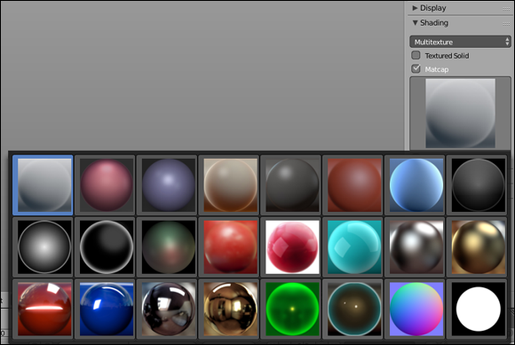
Figure: Blender's matcaps can be enabled in the Shading panel of the 3D View's Properties region.
Of course, there are a few things to keep in mind if you choose to use matcaps in the 3D View:
· The matcap is applied to all objects visible from the 3D View, whether you're sculpting them or not.
Fortunately, this is easy to get around using layers or local view (Numpad-slash { / }).
· If you're working in Blender with an older computer or an under-powered video card, you may experience some performance slowdowns if you enable matcaps in the 3D View.
Aside from upgrading your hardware, there's not a clean workaround for this. I've had some success splitting my 3D View (or duplicating it to a separate window) and the matcap display visible there while I sculpt in another 3D View with matcaps disabled. If you do that, the matcap view will only update when you finish strokes, so you get the benefit of snappy performance in one 3D View with the matcap visualization after each brush stroke in the other view.
All told, matcaps are a fantastically useful feature for 3D sculptors and modelers. It's worth it to try to take advantage of them as part of your modeling process.
Sculpting options
Figure 5-18 shows the contents of the Tools tab as well as the Options tab in the Tool Shelf when you’re in Sculpt mode. The buttons in these panels — Brush, Stroke, Curve, Dyntopo, Texture, and Symmetry/Lock in the Tools tab, and Overlay, Options, and Appearance in the Options tab — are for customizing your sculpt brushes as you work. On the left of Figure 5-18 are the panels in the Tools tab; on the right are the panels in the Options tab.
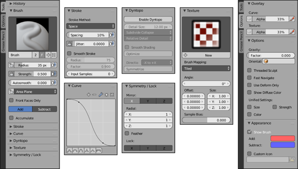
Figure 5-18: Panels in the Tool Shelf that are specific to Sculpt mode. On the left are the panels in the Tools tab and on the right are the panels in the Options tab.
Brush types
As you work your way down the Tool Shelf, you get finer and finer control of your brush. In fact, the first panel, Brush, just contains a list of brush datablocks, which serve as presets for all the subsequent settings in the Tool Shelf. Switch your brushes by clicking on the brush icon above the datablock and choose the preset brush you're interested in. By default, 18 presets appear in this list, each one modifying your mesh in a very specific way. All brushes work by left-clicking with the brush cursor over the mesh and dragging your mouse cursor around the 3D View. Due to this brush-style of editing, using a drawing tablet can be very beneficial.
Here are brief descriptions of some of the most used sculpt brushes in the list (if the brush has a hotkey, I include it next to the brush name in parentheses):
· Blob: When you sculpt with the Blob brush, vertices under your brush stroke are pushed outward or inward in a spherical shape.
This brush is good for adding or removing large forms to or from your mesh when creating rough starting sculpts.
· Clay (C): The Clay brush is pretty unique among Blender's sculpt brushes. Its primary purpose is to make large changes, adding or subtracting volume from your base mesh and dealing with details later.
Unlike the SculptDraw brush, which just moves vertices along their local normals, the Clay brush uses a reference plane that you can customize from this brush's settings. The Clay brush is also useful for merging unlinked meshes within the same object.
· Clay Strips: This brush behaves similarly to the regular Clay brush, but the technical difference is that it uses a cube to define the brush area instead of a sphere like the Clay brush.
In practice, you should find that the Clay Strips brush feels more like you're building up layers of clay as you work and often yields a textured surface with a bunch of wrinkles and ridges.
· Crease (Shift+C): In a way, the Crease brush is the opposite of the Blob brush. Rather than pushing vertices away from the center of the brush cursor, the Crease brush pulls vertices closer, sharpening indentations and ridges alike. In contrast to the Pinch/Magnify brush, the Crease brush uses a reference plane, much like the Clay brush does.
· Fill/Deepen: Using Fill/Deepen brush, you can (depending on the brush settings) raise recessed vertices on your mesh as if filling a ditch or you can deepen that ditch without having an effect on the vertices that are at “sea level.”
· Flatten/Contrast (Shift+T): The Flatten setting of this brush lowers or raises vertices to an average height in an attempt to get them to be as flat, or planar, as possible. If you're sculpting a landscape and you decide to remove a hill, this brush is the one to use. The other setting for this brush, Contrast, pushes vertices up and down away from that average height, increasing the overall distance between them.
· Grab (G): When you left-click and drag your mouse cursor on a mesh with the Grab brush activated, the vertices that are within the brush cursor's circle are moved to wherever you drag your mouse to. Grab is like selecting a bunch of vertices in Edit mode and pressing G. In fact, you can also quickly choose this brush in Sculpt mode by pressing G, too.
On a related note, if you're using dyntopo, the Grab brush is one of the few that doesn't add or remove vertices to your mesh. It just moves them around. If you want to add and remove vertices while moving them around, try the Snake Hook brush described a few bullet points after this one.
· Inflate/Deflate (I): When you run the Inflate/Deflate brush over your mesh, vertices move outward along their own local normals. If the Subtract button in the Brush panel is enabled, the vertices move inward. This brush is good for fattening or shrinking parts of a model. The difference between this brush and the Blob brush is that Blob inflates vertices in a distinctly spherical way, whereas the Inflate/Deflate brush works purely based on vertex normals.
· Layer (L): The Layer brush is like using the SculptDraw brush with a maximum height that it pulls the vertices, basically creating a raised mesa on the surface of your mesh. For a simple mnemonic, remember that the Layer brush relates to the SculptDraw brush in the same way that the Clay Strips brush relates to the Clay brush.
· Mask (M): There are occasions in sculpting when you want to preserve a part of your mesh and prevent yourself from accidentally sculpting those vertices. The Mask brush was created specifically for that purpose. Enable the Mask brush and you can paint the vertices on your mesh that you wish to protect.
· Nudge: Using the Nudge brush, you can push vertices a bit at a time in the direction of your brush stroke. Think of it as a much more nuanced version of the Grab brush.
· Pinch/Magnify (P): If you enable the Pinch/Magnify brush, vertices are pulled toward the center of your brush cursor as you move it over the surface of the mesh. Pinch is a great way to add ridges and creases to a model, though perhaps with a bit less control than you have with the Crease brush, which more frequently pushes topology inward or outward.
· Scrape/Peaks: The Scrape/Peaks brush is the logical opposite of the Fill/Deepen brush. Whereas Fill/Deepen raises or lowers only the vertices that are below “sea level,” the Scrape/Peaks brush only works on vertices that are above sea level. In practical application, you use this brush to flatten mountains or grow them larger.
· SculptDraw: The SculptDraw brush is the default brush and it basically pulls the surface of your mesh outward (or inward, if you enable the Subtract button in the Brush panel). By default, the brush works with an even falloff, so the raised areas you draw tend to flow smoothly back into the rest of the mesh.
· Smooth (S): If you have jagged parts of your mesh or undesirable surface irregularities created while sculpting, using the Smooth brush cleans up those bumpy parts and makes the surface of your mesh, well, smoother.
By pressing and holding Shift while you sculpt, you can have quick access to the Smooth brush at any time, regardless of your current active brush. This quick access feature makes for a very fast sculpting workflow.
· Snake Hook: The Snake Hook brush is very similar to the Grab brush except it gives you more control over what you can do when you pull the vertices away from the main portion of your mesh. This is especially true if you're sculpting with dyntopo enabled, because the Snake Hook brush generates new geometry and the Grab brush doesn't. With enough geometry, you can actually sketch in 3D with the Snake Hook brush. It's useful for making things like spines, tentacles, and dreadlocks.
· Thumb: To think about the Thumb brush effectively, imagine you're working with real clay. If you put your thumb on the clay surface and massage it in a particular direction, the area under your thumb also flattens out. That's the basic effect of the Thumb brush. It's like the Nudge brush with the additional feature of flattening the area that you push.
· Twist: Most of the other Sculpt mode brushes are primarily means of translating or scaling vertices. The Twist brush, in contrast, is a brush for rotating vertices in your mesh. When you left-click and drag your mouse on your mesh, the brush remains stationary and the position of your mouse cursor determines how much the vertices within the area of your brush rotate.
Brush controls
The Radius and Strength sliders below the list of brush datablocks control the size and strength of the brush you're currently using. You can use hotkeys for changing these values while in the 3D View so that you don't have to constantly return to the Tool Shelf:
· To change brush radius, press F, move your mouse until the brush cursor is the desired size, and left-click to confirm.
· To adjust the brush strength, press Shift+F and move your mouse cursor toward the center of the circle that appears to increase the strength or away from the center to decrease the strength. When you're at the strength you want, left-click to confirm.
Additionally, if you happen to have a drawing tablet, you can bind the Radius and Strength values to the pressure sensitivity of your tablet. Each value slider has a button to its right with an icon of a hand pushing against a blue line with its index finger. Left-click this toggle button on either slider, and Blender recognizes the pressure information from your tablet.
The next set of important controls available while in Sculpt mode are a pair of buttons in the Brush panel. Depending on which brush preset you're using, these labels may be named Add and Subtract, Flatten and Contrast, Inflate and Deflate, or they may not be there (for grabbing brushes like Grab, Snake Hook, and Twist). Regardless of what they're named, if they appear, the first button (Add, Flatten, Inflate) is the default behavior for sculpting brushes. If you enable the second button (Subtract, Contrast, Deflate), it does the inverse of the default behavior. For example, with Subtract enabled, the Clay brush pushes vertices into the volume of your mesh instead of pulling them out.
Also, note that regardless of whether you enabled the first or second button in this block, pressing Ctrl while using the brush does the opposite behavior. For example, if you're using the SculptDraw brush with Add enabled, the normal behavior creates a small hill wherever you move your mouse cursor. If you Ctrl+left-click and drag, you sculpt a small valley instead.
When working with brushes like SculptDraw, Inflate, or Layer, an additional check box, labeled Accumulate, appears under the Add/Subtract buttons. By default, when you use these brushes, they move the faces on your mesh relative to the normals that they have when you start making your stroke, regardless of how many times you paint over them in a single stroke. This default behavior is helpful because it prevents your mesh from quickly expanding uncontrollably. However, if you want to use a face's immediate normal when you run your brush over it, then you should enable this check box.
Other settings in the Sculpt mode Tool Shelf
The next few panels in the Tool Shelf while in Sculpt mode — Texture, Stroke, Curve, and Symmetry/Lock in the Tools tab, and Overlay, Options, and Appearance in the Options tab — are devoted to creating custom brushes. The next section gets into custom brushes in more detail. The following describes each panel in the Tools tab:
· Texture: Any texture you can create in Blender can be used in a brush. The Texture panel is where you assign a texture to your current brush. See Chapter 8 for more information on creating textures. If you already have textures created in your file, left-clicking the texture icon gives you the ability to choose which one you want to use on your active brush.
· Stroke: The Stroke panel holds settings that dictate what happens when you’re dragging the brush over your mesh. The most valuable setting in this panel is Stroke Method. The options in this menu dictate how your brush movement influences your mesh. For fun, choose the Layer brush and set the Stroke Method to Anchor. When you left-click and drag your brush over your model, you get a neat mesh tsunami that originates from the location you clicked.
· Curve: Within this panel are settings for adjusting how the influence of your brush changes from its center to its extremities.
· Dyntopo: If you choose to enable dyntopo for dynamic topology sculpting, your controls for dyntopo behavior are in this panel, as covered in detail earlier in this chapter.
· Symmetry/Lock: This panel controls how the sculpt brushes modify your mesh relative to the object's local axes. For example, if you left-click the X check box, anything you do on the left side of the mesh automatically also happens on the right side of the mesh. Symmetry is an excellent timesaver for doing involved tasks like sculpting faces. The X, Y, and Z lock buttons in this panel prevent your sculpted vertices from moving along any of those axes if they're enabled.
There are also additional panels specific to sculpting in the Options tab of the Tool Shelf:
· Overlay: Overlays give you more detail about the nature of your brush. They can show the fall-off curve of the brush as well as the texture you're using. However, they can have a significant impact on the responsiveness of the 3D View when you're sculpting. Use the settings in this panel to enable overlays and control how much they're visible as well as when (that is, you can make it so overlays only appear when you're not drawing a stroke).
· Options: The settings in this panel are commonly used to speed up your performance while sculpting. In particular, the Threaded Sculpt and Fast Navigate check boxes are very helpful. Threaded Sculpt (enabled by default) toggles Blender's ability to take advantage of all the cores of your CPU if your computer has more than one; Fast Navigate (disabled by default) drops the subdivision level of your mesh while orbiting in the 3D View. The Fast Navigate option is only relevant if you're sculpting with the Multiresolution modifier on your mesh.
· Appearance: From the Appearance panel, you can stipulate whether your brush is visible and what color to use for your brush's outline if it is. Also, if you have an image that you'd like to use as a custom icon for your custom brush, you can enable the Custom Icon check box and point Blender to the location of that image on your hard drive. Then that image will appear as the representation of your custom brush in the brushes menu at the top of the Tool Shelf. This is particularly useful if you start creating your own custom brushes, as described in the next section.
The importance of good topology
If you listen to modelers talk or if you visit some of the Web forums where 3D modelers hang out, you'll hear the words topology and edge flow pretty often. These concepts are very important for a modeler, particularly if your model is destined to be animated. These terms refer to how the vertices and edges of your mesh lay out across its surface. Even when sculpting, 3D modelers will often use a base mesh that has good topology as their starting point. Or, when they're done sculpting, they'll take the model through a process known as retopology to give it a clean edge flow that's usable in animation. To that end, whether you’re sculpting or just straight modeling, keep a few key guidelines in mind:
· Use quads. Try to avoid triangles and ngons in your final mesh whenever possible. They're fine to use as stand-ins while your work, but four-sided polygons look better when subdivided, and they also tend to deform more cleanly when an armature is used to animate them.
· Minimize the use of poles that don't have four edges. Remember that a pole is where multiple edges join at a single vertex. The UV Sphere mesh has two large poles at its top and bottom. Poles are harder to avoid than triangles, but you should do what you can to minimize their use because they can terminate edge loops, and they don't deform as nicely as four-edged poles. If you’re forced to use a pole, try to put it in a place on the mesh that won't deform a lot when it's animated.
· Holes such as mouths and eye sockets should be encircled by concentric edge loops. This guideline is particularly important for character models that may be animated. Having concentric edge loops makes it easier to deform and animate these highly expressive parts of the face.
· Edges should follow anatomy (at least on the face). Following the flow of anatomy — particularly musculature — is important on face models because doing so yields cleaner, more natural deformations. For instance, the crease from the side of the nose flows around the mouth. For limbs, following musculature is less imperative; tube-type topology usually should be fine. But if you're aiming for anatomical realism in your models, following these little rules really makes the lives of riggers and animators much easier (and it helps make the final animation look better).
Creating custom brushes
Using the controls in the Tool Shelf while in Sculpt Mode, you can create your own custom brush datablock. Use the following steps:
1. Create a new brush datablock by clicking the Plus (+) button in the datablock beneath the list of brushes in the Brush panel at the top of the Tool Shelf.
Adding a new brush datablock in this manner duplicates the current active brush. So for efficiency, select the brush most similar to the custom one you want to create before adding.
2. Name your new brush by typing in the datablock field.
Now you can go about customizing your brush.
Using Blender's texture system to tweak brushes
In the Texture panel, you can pick a texture to influence the behavior of your brush. Any texture made in Texture Properties can be used as a brush when you sculpt. Textured brushes are an excellent way to get more details added to your mesh while sculpting. Choose an existing texture by left-clicking the texture square in this panel and picking from the thumbnail images that appear. (See Chapter 8 for more information on creating and loading textures in Blender.) Refer to Figure 5-18 to see the Texture panel in Sculpt mode's Tool Shelf.
You may want to choose the Rake option from the Texture Angle Source drop-down menu when you've loaded a texture. With this option chosen, the texture is rotated as you sculpt to match the motion of the brush. Using Rake helps you avoid creating unnatural patterns from your textures when you sculpt.
If you're sculpting with the Multiresolution modifier and you have a high level of subdivisions, it can be taxing on your computer, using a lot of memory to store all those additional vertices. If you use too many levels of subdivision, your computer may run out of memory, and Blender may lock up or crash. This can also happen if you're sculpting with dyntopo and add a lot of fine details to your sculpt. In an effort to prevent a crash and give themselves more vertices to play with, many 3D sculptors in Blender often go to the User Preferences under Editing to disable Global Undo and change the number of undo steps from the default value of 32 down to 0. This modification removes the safety net of undo, but it can often significantly improve Blender's performance while sculpting.
Understanding the basics of retopology
When it comes to doing retopo, Blender doesn't really have much in the way of dedicated tools built into it. A few very useful add-ons, such as Contours and Polystrips (or their bundled combination, RetopoFlow), have been created by third-party developers to help with the retopo process, but they don't ship with Blender by default. That said, if you find that sculpting and modeling are your favorite aspects of 3D computer graphics, you'll be going through the retopo process a lot. In that situation, I recommend that you investigate and ultimately purchase those add-ons. But it's still worthwhile to know what Blender can do on its own as well. Retopo add-ons can get you part of the way there, but most of the time, you still need to finish with Blender's native tools.
So if there aren't any dedicated retopo tools in Blender, exactly how do you retopologize your mesh? The answer is deceptively simple. You combine Blender's native modeling tools with clever use of snapping (see Chapter 3 for a more thorough overview of snapping). There are some shortcuts, such as trying to use the Shrinkwrap modifier to snap the vertices of a clean topology mesh to the surface of your sculpt. However, when it comes down to it, you're really going to need to do point-for-point modeling.
Once you finish your 3D sculpt, use the following steps as the basic process for retopologizing:
1. From Object mode, create a new mesh (Shift+A⇒Mesh⇒Plane).
In this example, I'm using a plane, but it could be any mesh, as you'll see in the next step. In fact, some modelers use an add-on that creates a zero-vertex mesh object for exactly this kind of thing.
2. Rename your new mesh object to something that makes sense.
It could be something like Character.retopo, for example, as long as it's anything other than the primitive mesh's name.
3. Tab into Edit mode on your new mesh.
4. Select all of the vertices in this new mesh and delete them.
Now you have a mesh object with no data inside.
5. Enable snapping (Shift+Tab or left-click the button with the magnet icon in the 3D View's header).
Also, make sure that the Snap Element drop-down menu is set to use face snapping. This step is important; it's what makes the rest of the retopo process possible.
6. Ctrl+left-click on the surface of your 3D sculpt.
This creates the first vertex of your retopo mesh. By enabling face snapping, your new vertex should be located right on the surface of your sculpt mesh.
7. Extruding from that first vertex (Ctrl+left-click or E), use point-to-point modeling techniques to lay out the vertices of your retopo'd mesh.
As you work, keep in mind the basic guidelines outlined in the sidebar in this chapter,“The importance of good topology”. This step comprises the somewhat tedious and time-consuming process of retopologizing your mesh. However, when you've already made your sculpt, you have a clear plan that shows what your final mesh should look like. At this point, you're basically playing “connect the dots” on the surface of your 3D sculpt. Once you get up to speed, this is a much more effective way of modeling than traditional box modeling or point-to-point modeling methods.
Figure 5-19 shows a mesh sculpted using dyntopo and that same model after it's been retopo'd.
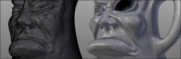
Figure 5-19: On the left, a model sculpted with dyntopo; on the right is the same model after being retopologized.
All materials on the site are licensed Creative Commons Attribution-Sharealike 3.0 Unported CC BY-SA 3.0 & GNU Free Documentation License (GFDL)
If you are the copyright holder of any material contained on our site and intend to remove it, please contact our site administrator for approval.
© 2016-2026 All site design rights belong to S.Y.A.