Software Engineering: A Methodical Approach (2014)
PART G. Appendices
Appendix 6. Specifying Object Behavior
This chapter focuses on specifying object behavior. The chapter has the following captions:
· Use-cases
· States and State Transitions
· Finite State Machines
· Event Diagrams
· Triggers
· Activity Diagrams
· Sequence Diagrams and Collaboration Diagrams
· Object Flow Diagrams
· Summary and Concluding Remarks
A6.1 Use-cases
The technique called use-case was first introduced by Ivar Jacobson in [Jacobson, 1992], and has since then been embraced by the software engineering industry. A use-case is a representation of all possible interactions (via messages) among a system and one or more actors in response to some initial stimulus by one of its actors. The use-case describes the functionality provided by a system, in order to yield a visible result for one of its actors.
In constructing use-cases, a few terms need to be clarified:

The use-case allows the user to view the system from a high level, focusing on possible interactions between the system and its actors. In a way, use-cases should remind you of data flow diagrams (DFDs) in functional design.
A6.1.1 Symbols Used in Use-case
Figure A6-1 includes the symbols used in use-case diagrams. As an example, consider the CUAIS project, and let us focus on the scenario where a student may register for a course, change his/her registration (for instance, auditing a course previously registered for), or drop a course. In the same vein, a department representative could add a course, cancel a course, or modify a course offering (changing its room and/or time period). Figure A6-2 illustrates a use-case diagram for this scenario.
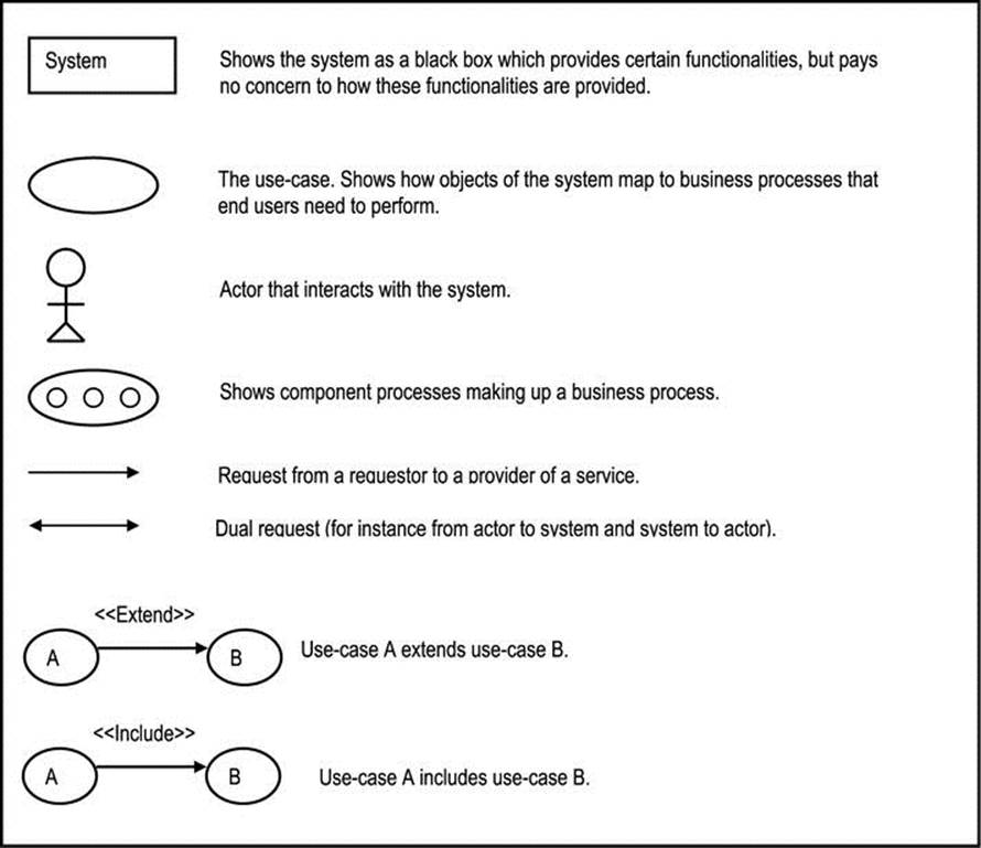
Figure A6-1. Symbols Used in Use-case Diagrams

Figure A6-2. Use-case for Registration Process
A6.1.2 Types of Use-cases
Use-case diagrams can be constructed for different levels of system functionality (they could be high-level or low-level):
· A high-level operation provides the essence of the business values provided.
· A low-level operation provides more detail about component or concurrent activities and their order.
Use-cases may also be classified in terms of primary or secondary operations that they represent:
· Primary operations relate directly to the essential business functionalities of the system. They are the options provided to the end user.
· Secondary operations are those operations, which, though not directly accessible by the end user, are essential for the delivery of a coherent, robust system. They are also referred to as subservient operations.
A third perspective is to differentiate essential operations from concrete operations:
· Essential operations are business solutions that are platform independent.
· Concrete operations are design dependent.
A use-case may be high-level or low-level; primary or secondary; essential or concrete. It may also involve a mix of these classifications. Additionally, a use-case may include a previously defined use-case, or it may extend a previously defined use-case.
A6.1.3 Information Conveyed by a Use-case
A use-case may be used to convey the following information:
· Actors: These are the participating entities.
· Relationships with Other Use-cases: Two kinds of relationships are possible — the include relationship and the extend relationship.
· Pre-conditions: A pre-condition is a condition that must be satisfied prior to the invocation of the use-case.
· Post-conditions: A post-condition is a condition (or state) that must hold after the execution of the use-case.
· Details: This entails the step-by-step interactions among participating objects in the use-case.
· Constraints: Any constraint (apart from pre-conditions and post-conditions) that applies to the use-case must be specified. Constraints may be with respect to values and resources available for manipulation.
· Exceptions: This involves the identification of all possible errors that might occur in the use-case.
· Variants: This includes all variations that may apply.
Not all of this information may be relevant for each use-case; Figure A6-3 provides some guidelines.

Figure A6-3. Information Associated With Different Kinds of Use-cases
A6.1.4 Bundling Use-cases and Putting Them to Use
As pointed out earlier, a use-case bundle refers to a group of related use-case. Typically, the component use-cases make sense when the bundle is viewed from a business perspective. Use-cases may be bundled using any of the following criteria:
Same Actor, Same State: All use-cases involving the same actor and the same state are grouped. The use-cases of Figure A6-2 meet this criterion.
Common Entities: Use-cases are bundled based on the fact that they use and/or impact the same entities. The rule-of-thumb method for object identification, discussed in appendix 4 (section A4.1.10), flows naturally into this approach. For example, in designing an inventory management system, one may identify and refine use-cases relating to the purchase of an invoice. These would typically involve adding, modifying, deleting and inquiring on invoices.
Specific Workflow: Use-cases that relate to a particular actor (user) carrying out a functional responsibility are bundled together. More often than not, same-actor-same-state use-vases qualify as specific workflow use-cases. Figure A6-2 therefore applies here also. The idea here is that if we can identify, define and implement all the operations which each actor of the system requires, we would achieve a comprehensive system meeting user requirements.
Once the use-cases have been identified and represented (via use-case diagrams), the next step is to use the information to refine your system model. Remember, your focus is object behavior. The rest of the chapter will concentrate on some methodologies for analyzing and modeling system behavior.
A6.2 States and State Transition
An object can exist in one of many states. A state life cycle is the sequence of states that the object may be in during its useful life.
State changes trigger operations; operations invoke methods, which further result in state changes. For example: An employee may be hired, promoted, and eventually fired. Each of these operations results in state changes which are recorded in the object’s data.
A state transition diagram shows the allowable states of an object. Figure A6-4 and Figure A6-5 provide examples of state transition diagrams.

Figure A6-4. State Transition Diagram for Employee Object

Figure A6-5. State Transition Diagram for Airline Booking Object
An object may have more than one set of states. For example, in addition to the states indicated in Figure A6-5, a second set of states for a confirmed airline booking could be:
· Unpaid
· Deposit Paid
· Fully Paid
· Needs Refund
· Refunded
These additional states would exist between the states Confirmed and Fulfilled.
An object may have several states, which in turn may have sub-states. (In some OO-CASE tools, the state which has sub-states is usually indicated by a ‘+’. Clicking here causes the sub-states to be displayed.)
The two sets of states may be merged in the interest of simplicity. Alternately, the two sets of states may be linked by some conditionality (rule). For example: “Booking cannot be confirmed until payment state is either Deposit Paid or Fully Paid.”
A6.3 Finite State Machines
An alternative to the state transition diagram and the event diagrams is the finite state machine (FSM). This technique, though existent before object technology, finds very useful application in OOSE. A class may be considered as an FSM with methods, inheritance and encapsulation.
In an FSM (also referred to as a state-diagram) nodes are states; arcs are transitions labeled by operation names (the label on a transition arc is the operation name causing the transition). State name is written inside the node. Typically, an FSM is developed for a class; the operations represent the set of operations defined on the class; the state transitions represent the set of possible transitions for any instance of the class. Figure A6-6 illustrates an FSM for a class called Employee. This figure includes all the information provided in Figure A6-4, but also provides additional information.

Figure A6-6. FSM for Employee Object
On the FSM, there is no distinction between an event (discussed next) and an operation. This is reasonable, since as you will soon see, events and operations are intrinsically related (one leads to the other).
One significant advantage of the FSM is that you can show operations that do not cause change of state. A review of Figure A5-6 reveals that in several cases, there is a Modify operation that does not necessarily result in a state change. Another advantage is that the FSM is easy to draw, maintain, and understand.
A6.4 Event Diagrams
[Martin, 1993] describes event diagrams as a means of modeling the interrelationship between operations and events, as summarized in this section.
An event is a noteworthy change in the state of an object. Events trigger operations. An operation may change the state of an object thereby causing another event. The event diagram shows these events and their associated operations.
An event is represented by a filled in triangle; an operation is represented by a round-cornered box (shadowed if operation is external). When an event results from an operation, the triangle is attached to the operation box. An example is shown in Figure A6-7, where an event diagram is shown for the processing of a purchase order.

Figure A6-7. An Event Diagram for Processing a Purchase Order
The event diagram relates to the state transition diagram in the following way: the latter depicts state changes; the former depicts causes for those state changes. On the state transition diagram, each transition may be elaborated by an event diagram. State transition diagram and event diagram are complementary. The one assists in ensuring the accuracy of the other. With an OO-CASE tool, the designer chooses to work with either.
The operation is isolated from cause and effect. Each object type (class) has an associated state transition diagram and event diagram(s).
The event diagram is to OOSE what the program flowchart is to the more traditional (function-oriented) approach to software engineering. In more complex environments, operation specifications may be required to compliment the event diagrams.
An operation may have pre-condition(s) and post-condition(s). Pre-conditions must be true before the operation can take place; post-conditions must hold after the operation is completed. Pre-conditions and post-conditions are referred to as control conditions. The diamond symbol ofFigure A6-6 indicates that pre-condition(s) exist for the operation Close Order. With an OO-CASE, pre-conditions can be clicked for details.
Just as there are object types, there are event types. The analyst is more interested in event types than the number of occurrences of each event. Typically event types describe the following kinds of changes:
· Creation of new object
· Termination of object
· An object changes classification
· An object’s attribute(s) is (are) changed
· Object is classified as an instance of another type; for example: Lecturer becomes Department Chair
· Object is declassified; for example: Lecturer ceases to be Department Chair
Control conditions are particularly useful when multiple trigger rules lead to a specific operation, as illustrated in Figure A6-8. In the figure, Operation A, Operation B, and Operation C must occur before Operation D can occur.

Figure A6-8. Illustrating Control Condition
Events may also have subtypes and super-types as illustrated in Figure A6-9. In this figure, Operation A has two sub-events.
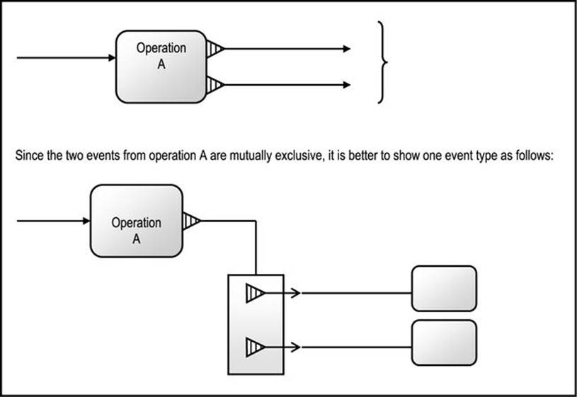
Figure A6-9. Illustrating Event Sub-types
A6.5 Triggers
[Martin, 1993] also describes and trigger rules — two related concepts that have become commonplace in contemporary software engineering environments. The line going from an event to the operation(s) it triggers, represents a trigger rule. The trigger rule defines the causal relationship between event and operation(s). An event may trigger one or more operations; also, an operation may be caused by multiple triggers (Figure A6-10 illustrates).
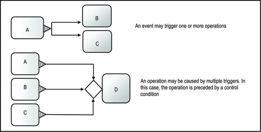
Figure A6-10. Illustrating the Relationship between Triggers and Operations
Like objects types, operations may have subtypes and super-types as illustrated in Figure A6-11.
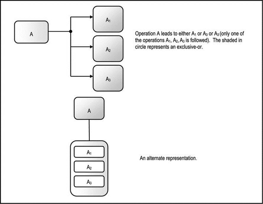
Figure A6-11. Illustrating Operation Sub-types
A6.6 Activity Diagrams
As an alternative to event diagrams, UML supports activity diagrams. An activity diagram describes how related activities (computations and workflow) are coordinated. Bear in mind that activities are not existence independent, but are typically subservient to operations and other activities.
The activity diagram (graph) depicts activity states and the transition among activities in a workflow. An activity state represents the execution of a statement in a procedure, or the performance of an activity in a workflow.
The activity diagram conveys information about sequential activities as well as concurrent activities (threads). Figure A6-12 shows the UML notations for activity diagrams, while Figure A6-13 provides an example.

Figure A6-12. UML Notations for Activity Diagram
The activity diagram may contain swim-lanes: Whenever the situation arises where it is desirable to group related activities of a process into distinct partitions (these partitions may represent functional areas in a business), vertical or horizontal lines are used to define the partitions. The partitions are called swim-lanes. Swim-lanes could have been introduced for the three concurrent threads in Figure A6-13 (they were omitted since their introduction would have cluttered the diagram).

Figure A6-13. Activity Diagram for Adding Employee Information
A6.7 Sequence Diagrams and Collaboration Diagrams
Another UML notation is the collaboration diagram. A collaboration diagram (also described in older literature on object technology as an object interaction diagram) is a special class diagram that is used to depict various interactions among objects that participate in a process.
The collaboration diagram is useful in illustrating the implementation of a class operation, or the set of operations of a class. It includes permanent objects as well as objects created and/or destroyed during the process. Figure A6-14 illustrates a collaboration diagram for an inquiry on student information in the CUAIS project of earlier discussions. A message from one object to another is represented as a directed arrow, labeled with the name of the service requested and an argument list.

Figure A6-14. Collaboration Diagram for Inquiry on Student Information
A sequence diagram — another UML notation — shows how objects interact with each other (via messages) with respect to time, in a two dimensional chart. The vertical dimension indicates time, which increases down the axis. The horizontal dimension indicates the objects in the interaction. Except for real time systems, sequence diagrams are not as widely used as the other techniques discussed; they are therefore not discussed any further. For additional information, see the recommended readings [Lee, 2002] and [Rumbaugh, 1999].
A6.8 Object Flow Diagrams
An object flow diagram (OFD) is similar to a high-level data flow diagram (DFD) in traditional software engineering. It is non-executable, and often used as a system overview diagram. It indicates communication lines among the main components (subsystems or super-classes) at a very high level. Figure A6-15 illustrates an OFD for a financial management system, which assumes a client-server approach or a component-based approach for the system architecture. Figure A6-16 illustrates another OFD — this time for the CUAIS project — which assumes a repository approach for the system architecture.

Figure A6-15. An OFD for a Financial Management System
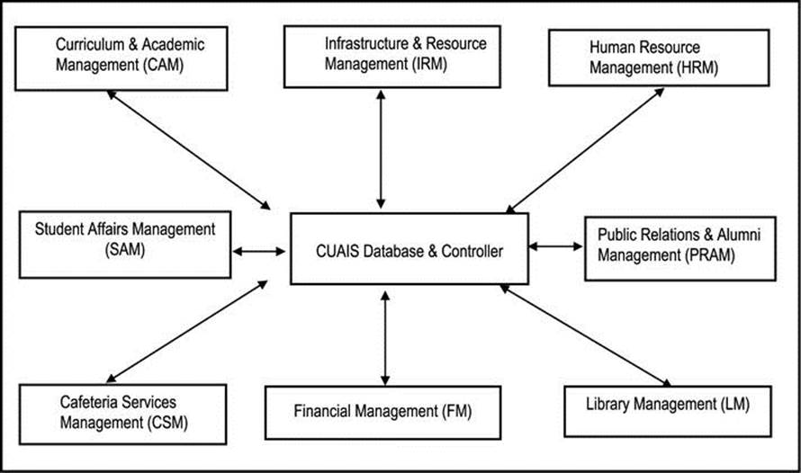
Figure A6-16. OFD for the CUAIS Project, Assuming Repository Model
A6.9 Summary and Concluding Remarks
Let us summarized what has been discussed in this chapter:
· A use-case is a representation of all possible interactions (via messages) among a system and one or more actors in response to some initial stimulus by one of its actors. The use-case describes the functionality provided by a system, in order to yield a visible result for one of its actors.
· A state transition diagram (STD) is a diagram that represents the possible states that an object can be in. An alternate diagram is a finite state machine (FSM). In addition to indicating the possible states, the FSM also shows the operations that lead to state changes.
· An event diagram represents the details of operations comprising a system and the events they lead to.
· As an alternative to event diagrams, UML supports activity diagrams. An activity diagram describes how related activities (computations and workflow) are coordinated. The activity diagram depicts activity states and the transition among activities in a workflow. An activity state represents the execution of a statement in a procedure, or the performance of an activity in a workflow.
· A collaboration diagram is useful in illustrating the implementation of a class operation, or the set of operations of a class. It includes permanent objects as well as objects created and/or destroyed during the process.
· An object flow diagram (OFD) is often used as a system overview diagram. It indicates the main objects and activities of the system at a very high level.
Other techniques have been proposed for depicting object behavior, which have not been covered in this chapter. The ones covered are considered essential for constructing a comprehensive model of the software system or information infrastructure that has your focus. The next chapter discusses tools that support OOM.
A6.10 References and/or Recommended Reading
[Bruegge, 2000] Bruegge, Bernard and Allen H. Dutoit. Object Oriented Software Engineering: Conquering Complex and Changing Systems. Upper Saddle River, NJ: Prentice Hall, 2000. See chapter 2.
[Jacobson, 1992] Jacobson, Ivar. Object Oriented Software Engineering – A Use Case Approach. Reading, MA: Addison-Wesley, 1992.
[Lee, 2002] Lee, Richard C. and William M. Tepfenhart. Practical Object-Oriented Development WithUML and Java. Upper Saddle River, NJ: Prentice Hall, 2002. See chapters 3, 5, 6-8.
[Martin, 1993] Martin, James and James Odell. Principles of Object Oriented Analysis and Design. Eaglewood Cliffs, NJ: Pretence Hall, 1993. See chapters 8 and 9.
[Rumbaugh, 1991] Rumbaugh, James, et. al. Object Oriented Modeling And Design. Eaglewood Cliffs, New Jersey: Pretence Hall, 1991. See chapters 5 and 6.
[Rumbaugh, 1999] Rumbaugh, James, Ivar Jacobson and Grady Booch. The Unified Modeling Language Reference Manual. Reading, MA: Addison-Wesley, 1999. See chapter 8.