Knowledge-based Configuration: From Research to Business Cases, FIRST EDITION (2014)
Part II. Basics
Chapter 10. Smarthome Configuration Model
Lothar Hotz and Katharina Wolter, HITeC e.V., University of Hamburg, Hamburg, Germany
Abstract
In this chapter, we present a configuration model taken from a building automation domain. It provides complex aspects of configuration models such as separation of features of a system from realizing system components and domain-dependent workflows for the configuration process.
Keywords
Knowledge-based Configuration; Smarthomes; Building Automation systems; Feature Models; System Models; Configuration Workflow; Constraints
10.1 Introduction
This chapter presents an example of a configuration model of a building automation system. The task in this domain is to compose functionalities of a building, such as controlling sun blinds, regulating air conditioning systems, and monitoring lift facilities. In contrast to the working example introduced in Hotz et al. (2014),1 the domain of building automation systems is more complex. This is due to (1) the higher number of attributed technical component types, (2) a combination of different models representing different aspects of the domain, and (3) the modeling of a configuration workflow.
Besides the various knowledge types that are needed for solving configuration problems, the example introduces how to model features and components of the domain. Features are characteristics of products that are visible to the customers (Kang et al., 1990). The composition of the technical components to the actual building automation system makes sure that the features are accomplished (we say the components realize the features). Distinct submodels separate features and components; constraints and relations relate both.
Furthermore, the example emphasizes the aspect of modeling the workflow of a configuration process. A workflow takes dependencies between configuration decisions into account and, thus, ensures an effective configuration process.
In summary, this complex configuration model example demonstrates the usage of knowledge-based configuration techniques in a technical area. We thereby concentrate on different representation aspects and, thus, do not focus on a complete model.2
In the subsequent sections, we introduce the configuration model for the building automation domain (the Smarthome model). Section 10.2 introduces the terminology used in the Smarthome domain. Section 10.3 introduces the structure of the Smarthome model. Section 10.4 provides the constraints of the Smarthome model. Section 10.5 illustrates a workflow describing the configuration process for composing a specific building automation system. Section 10.6 summarizes the modeling and representation properties of the Smarthome model. Section 10.7 concludes the chapter.
10.2 Building Automation Systems: Domain
Building automation systems (Smarthome systems) provide the equipment for regulating, controlling, and monitoring functionalities of buildings. Depending on the type of buildings, different systems can be automated: lighting systems, solar radiation protection systems, sun blinds, air conditioning systems, heating systems, sanitary facilities, lift facilities, telecommunications systems, or safety systems.
Traditionally, if a building contains a number of such subsystems, they are controlled separately. This leads to high effort in wiring and less information exchange between the subsystems. By using a common bus (such as a Local Operating Network, LON3) a comprehensive system can be realized that allows a combined control of the subsystems. Devices from distinct areas such as lighting, solar radiation protection, and heating can be controlled via such a bus system. The connected systems can directly communicate with each other.
Figure 10.1 gives an example of a configuration of a Smarthome: An office consisting of a corridor, a main office room (e.g., for a head of an office), and a normal office room (e.g., for a clerk) is equipped with building automation facilities. The corridor has a dimmable light. The main office room has sun blinds, which are controlled by:
• A wind sensor that triggers the movement of the sun blinds as a means of protecting them against storms.
• A brightness sensor that triggers a lowering of the sun blinds if it becomes too bright in the room.
• A temperature sensor that triggers a lowering of the sun blinds if the temperature reaches a specific threshold (it could be too warm in the room and, as a consequence, the sun blinds should be down).
• A presence detector that activates the brightness sensor if somebody is in the room; that is, the sun blinds are operated solely when a sensor detects a presence in the room (on the premise that if the room is empty, it is not necessary to lower the sun blinds).
• A switch for allowing manual control of the sun blinds.
Additionally, the main office room has two light groups, one on the ceiling and the other above the desk. The one on the ceiling switches on if somebody is in the room, the one above the desk can be dimmed.
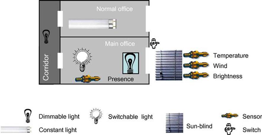
FIGURE 10.1 Example of a Smarthome configuration. The office layout includes a corridor, a normal office, and a main office, as well as components used for the building automation.
The normal office room has one light group, which is a constant light. It ensures constant lighting conditions in a room by taking the natural light into account (i.e., the light of the light group is dimmed according to the daylight in the room). For offices, constant lighting conditions are thus ensured throughout the day. In the office building, there is a control unit that controls centrally the office’s sun blinds and the light groups.
Examples of features are the detection of the presence of a person in a room or controlling the sun blinds depending on wind or temperature changes. The configuration task in this domain is to compose the various components according to given desired features of a building automation system.
10.3 Configuration Model: Structure
For separating functional characteristics and technical components of building automation systems, we divide the structure of the Smarthome model (represented by SmartHome) into a feature model (represented by SmartHomeFeature; see Subsection 10.3.1) and a system model (represented by SmartHomeSystem; see Subsection 10.3.2). These models allow a clear separation of functional characteristics (features) of a SmartHome from the components realizing these functionalities (see the association realize in Figures 10.2 and 10.3). The use of SmartHome as an aggregate with two parts, SmartHomeFeature and SmartHomeSystem, combines both aspects in the resulting configuration of one product.
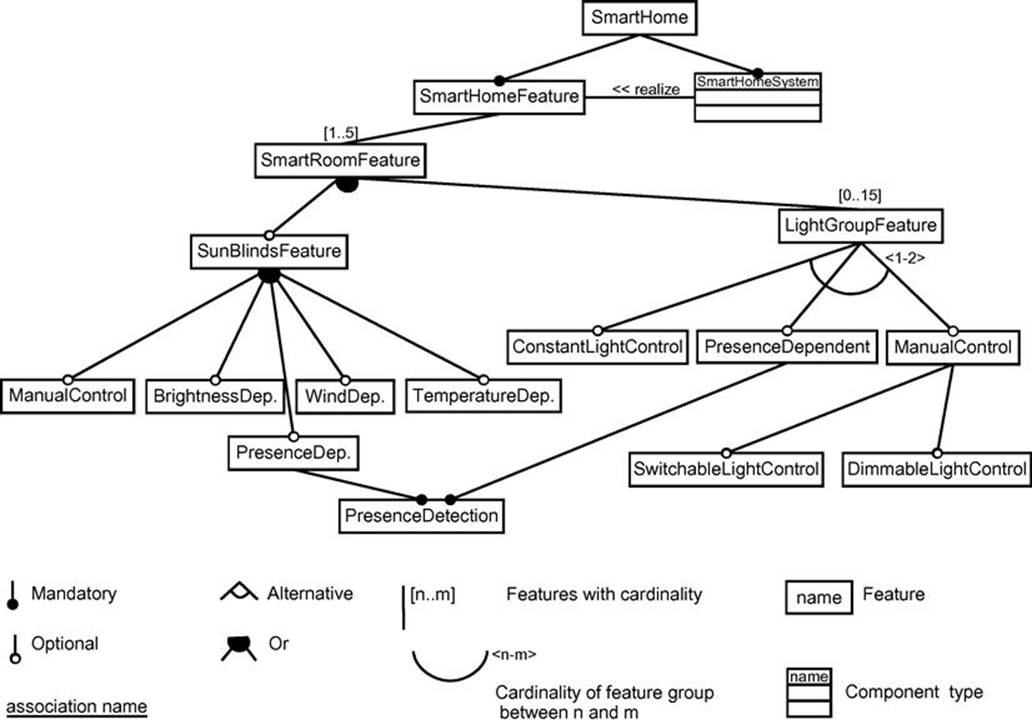
FIGURE 10.2 The Smarthome feature model with root feature SmartHomeFeature is related to the system model with root component type SmartHomeSystem through the association realize, (i.e., a SmartHomeSystem realizes the SmartHomeFeature). Both roots are part of the overall SmartHome model.
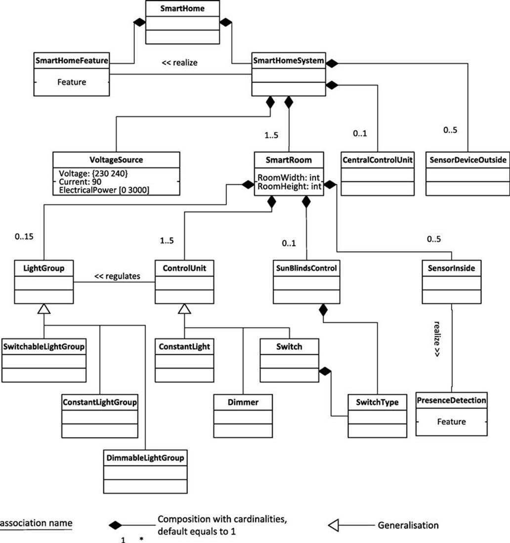
FIGURE 10.3 The Smarthome system model (Part 1; with root SmartHomeSystem) and its relationship to the feature model (with root SmartHomeFeature) through the directed association realize. One example for the realize association provides the inside sensor (SensorInside), which realizes the presence feature modeled in the feature model as PresenceDetection.
Both models exploit configuration knowledge representations as introduced in Hotz et al. (2014)4 and beyond. In particular, the presented models cover the following feature and component-related representation aspects, which will be explained in more detail in the following sections:
• Classes are used for representing features and component types. For example, the sun blinds feature is represented with the class SunBlindsFeature and a dimmer is represented with the component type Dimmer.
• Instances represent selected or inferred features or components for a certain configuration. Instances are not represented in the configuration model but created during the configuration process.
• Part-of with multiplicity is used to express feature–subfeature relations and aggregate–part relations. For example, if sun blinds are desired as a feature for a smartroom, then the user (customer) should also make a decision with respect to the (sub) feature controlling the sun blinds.
• Specialization is used for structuring the model with respect to common attributes. For example, a dimmer is a special control unit; consequently, it has all attributes of a control unit.
• Attributes are only used for components. For example, the power consumption of an electrical component is modeled by an attribute of a class. Features can typically be selected by a user and have no further attributes.
• Requires is used for expressing dependencies between components, features, or components and features. For examples, a switchable light group requires a switch.
• Incompatible-with is used for excluding features or components that cannot occur together. For example, a manual control is incompatible with a presence detection.
• Compatible is used for features or components that can be used together but must not. For example, a sun blind can be combined with a light group.
• Shared class is used for expressing common aspects of different features or components. For example, a presence detection feature can be shared by a sun blind and a light group feature but each instance shall have its own presence detection component.
• Connections/Associations express relations between features or components that are of particular interest in the domain. For example, a control unit is connected with a light group that it regulates.
In the following, we introduce only features, component types, and component attributes that are used in Section 10.4 for illustrating the constraints.
10.3.1 A Feature Model for Smarthomes
A feature model of major functional properties of a SmartHome is depicted in Figure 10.2. This model represents possible functional properties, or combination of features. However, the components of a Smarthome system do not allow all combinations of features; consequently, realizable combinations of features are further restricted by constraints (see Section 10.4).
Figure 10.2 presents the compositional structure that divides features into subfeatures (e.g., ManualControl is a subfeature of SunBlindsFeature). In addition to the compositional structure, a configuration model has to specify also the specialization relations between classes. In the feature model of Smarthomes represented here, the specialization hierarchy for features is flat; that is, all features are specializations of SmartHomeFeature (these specializations are omitted in Figure 10.2 for readability purposes).
We extend the notation used in Hotz et al. (2014)5 for feature models by cardinalities (following Czarnecki et al., 2005) and associations for relating the feature model to the system model shown in Figure 10.3. Cardinalities can be expressed for one feature (Features with cardinality) or for a feature group (Cardinality of feature group). A feature group is a collection of features and its cardinality specifies how many features are in the collection.
In our example, one Smarthome can have up to five rooms and, thus, the SmartHomeFeature can have up to five SmartRoomFeatures. Each room in a Smarthome has its own features. Each room might have one optional SunBlindsFeature and up to ![]() instances ofLightGroupFeature, which can have dedicated controls, as described in the following.
instances ofLightGroupFeature, which can have dedicated controls, as described in the following.
Controlling the Sun Blinds. As functional property, the user can select the controlling of the sun blinds; that is, his/her preferences about when the sun blinds should be lowered or raised. The sun blinds can be controlled manually or automatically depending on some environmental circumstances (see Section 10.2) such as
• The amount of light in the room (BrightnessDep.)
• The presence of a person in the room (PresenceDep.)
• A wind factor (WindDep.)
• The outside temperature (TemperatureDep.)
All these features are optional (indicated by ![]() ). However, at least one feature has to exist (indicated by
). However, at least one feature has to exist (indicated by ![]() ). The control alternatives can be combined when the customer selects multiple features; for example, a manual control of the sun blinds in combination with the temperature dependent control can be in one room. All combinations are possible, but the components needed for realizing a certain combination may vary (see the Constraint fsc-3 in Subsection 10.4.3).
). The control alternatives can be combined when the customer selects multiple features; for example, a manual control of the sun blinds in combination with the temperature dependent control can be in one room. All combinations are possible, but the components needed for realizing a certain combination may vary (see the Constraint fsc-3 in Subsection 10.4.3).
Controlling the Lights. As further functional property, the user can select the controlling of the lights in the room; that is, his/her preferences for the decision when the light should switch on or off. A LightGroupFeature represents this functional property. It consists of one or two features of type ConstantLightControl, PresenceDependent, or ManualControl (each one of these is optional). Thus, the feature group LightGroupFeature restricts the number of its members. A light group can be controlled automatically depending on the presence of a person (PresenceDependent of LightGroupFeature), it can be controlled manually (ManualControl of LightGroupFeature), or it can be a constant light (ConstantLightControl) that ensures constant lighting conditions. A manual control offers two options: It can either be a switch (SwitchableLightControl) or a dimmer (DimmableLightControl). However, not all combinations are possible; see Subsection 10.4.1.
A presence dependency feature (i.e., PresenceDep. of the SunBlindsFeature and PresenceDependent of the LightGroupFeature) has as mandatory feature, the PresenceDetection feature. This models the fact that the system somehow must detect the presence of a person in a room to allow presence-dependent control. The presence dependency features are more customer-oriented (user feature)—they can directly be selected by customers—whereas the PresenceDetection feature is more system related (system feature)—the system should have this feature, if the customer selects a presence dependency feature. The system feature PresenceDetection represents the connection to the system model by having an association to the realizing component SensorInside (see Figure 10.3).
10.3.2 A System Model of Smarthomes
Figures 10.3 and 10.4 present the system model of Smarthomes in two (for illustration reasons) separated parts. Figure 10.3 illustrates the definition of the compositional structure of the SmartHomeSystem and Figure 10.4 illustrates major parts of the generalization hierarchy. The following component types are defined:
• A SmartHomeSystem consists of a voltage source (VoltageSource), an optional central control unit (CentralControlUnit), up to five smart rooms (SmartRoom), and between zero and five outside sensors (SensorDeviceOutside).
• The CentralControlUnit allows a manual central regulation of all devices. The VoltageSource has to supply electrical power such that all network nodes can be included in the network.
• Each SmartRoom consists of light groups (LightGroup), control units (ControlUnit) such as switches (Switch) and dimmers (Dimmer), a sun-blinds control (SunBlindsControl), and several sensors (SensorInside).
• LightGroups include a number of lights that can be regulated together through a control unit (ControlUnit). A control unit can regulate several light groups (directed association regulates). A sun-blinds control (SunBlindsControl) regulates the sun blinds, which themselves are not part of the smart room model. Instances of SensorInside (i.e., sensors of the room) provide signals on the bus that are interpreted by an appropriate control.
• The outside sensors (SensorDeviceOutside) provide the sensor data for the control units. In our model, the SunBlindsControl interprets sensor data, while a ControlUnit reacts on sensor data as well as on manual actions (e.g., via a Switch). Specific sensors inside a room control the presence of a person in the room.
• The component types Switch and SunBlindsControl have a SwitchType. Thus, SwitchType is a shared class; however, each control has its individual switch type.
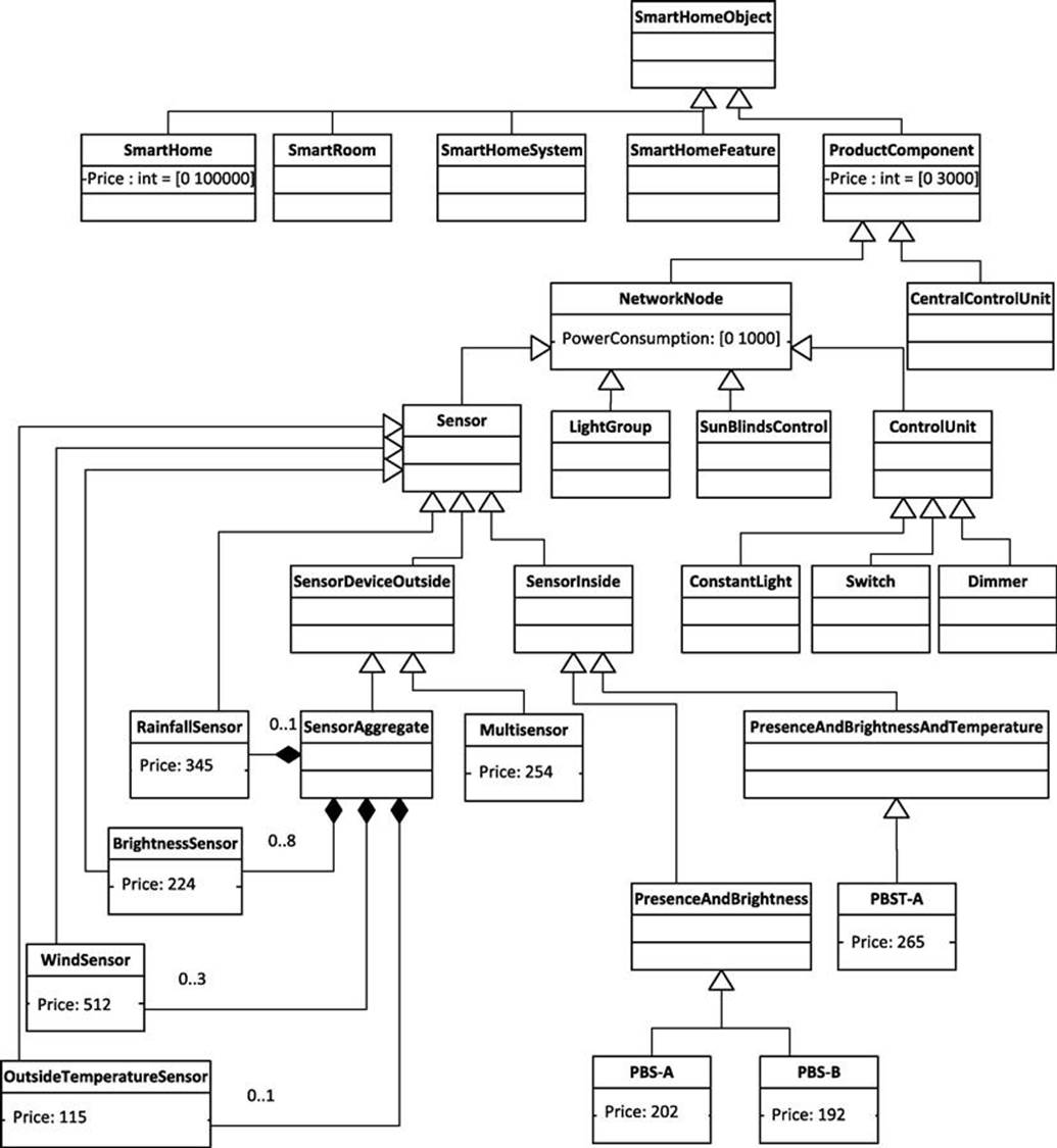
FIGURE 10.4 The Smarthome system model (Part 2) with component hierarchy including attributes. SmartHomeObject is the taxonomical root of all classes.
Figure 10.4 illustrates the generalization hierarchy of all classes used in the system model. While the compositional hierarchy is based on general classes, the generalization hierarchy includes specific components of certain companies. For example, the general class SensorInside is specialized into inside sensors that can detect both presence and brightness (here called PBS-A and PBS-B for Presence-Brightness Sensor, both of type PresenceAndBrightness) or additionally measure temperature (PBTS-A of typePresenceAndBrightnessAndTemperature).
As mentioned in Subsection 10.2, a local operating network connects the components. The class NetworkNode summarizes all components that are connected through the bus (i.e., sensors and control units). By doing so, it is possible to define attributes as well as constraints that apply to all network nodes. As an example, see the System Attribute Constraints in Subsection 10.4.2, which restrict the PowerConsumption of NetworkNodes.
The outside sensors (SensorDeviceOutside) can be specialized to the specific sensor device SensorAggregate that may contain several types of sensors (such as wind or temperature sensors) or can be specialized to Multisensor. The parts of SensorAggregate (i.e.,WindSensor, OutsideTemperatureSensor, BrightnessSensor, and RainfallSensor) are modeled as further sensors. A Multisensor covers brightness and presence sensors in one component. This choice between a combination of distinct sensors into a sensor aggregate and the use of one multisensor, which includes various sensors, is one of the major system-related decisions for a Smarthome system. Depending on the selected features, a combination of sensors or choice of the multisensor is possible. The Constraint fsc-3 represents this dependency (see Subsection 10.4.3 and Table 10.1). These sensors furthermore illustrate the use of attribute Price, which all basic component types have by inheriting it from ProductComponent. Thus, the attribute Price does not have to be modeled for each component type and only specific prices have to be defined for the more specific components.
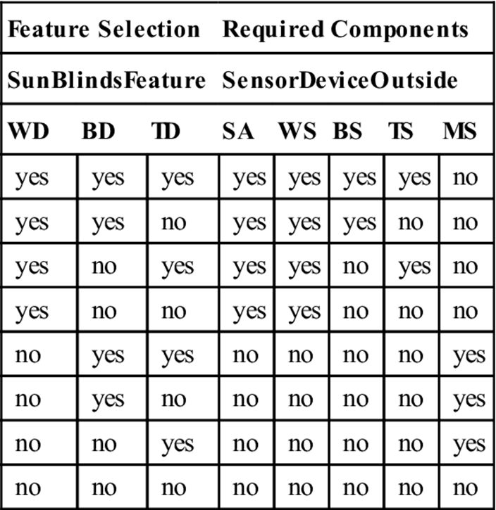
Table 10.1
Certain components realize combinations of the SunBlindsFeature. An extensional table represents the constraint fsc-3 by enumerating possible sensor combinations. The following abbreviations hold: WD: WindDep., BD: BrightnessDep., TD:TemperatureDep., SA: SensorAggregate, WS: WindSensor, BS: BrightnessSensor, TS: TemperatureSensor, MS: MultiSensor.
10.4 Configuration Model: Constraints
Like the structure model, we divide the constraints for a building automation system into feature model constraints (see Subsection 10.4.1) and system model constraints (see Subsection 10.4.2). Additionally, Subsection 10.4.3 provides constraints between the feature model and the system model. We provide an excerpt of constraint examples that illustrate the following constraint types: resource constraint, incompatibility and compatibility constraint, requires constraint, constraint for sharing classes, algebraic constraint for computations,n-ary cardinality constraint, all-constraint over an arbitrary number of attributes, and table constraint, which expresses a relation extensionally by enumerating possible combinations of variable values.
10.4.1 Feature Model Constraints
The feature model defined in Figure 10.2 specifies combinations of features. A reduction of these combinations is achieved by following incompatibility and requires Feature Model Constraints.
Incompatibility. A light group of type SwitchableLightControl is incompatible with a light group of type DimmableLightControl in the same room. Thus, both features cannot be selected at the same time by the user.
Constraint for sharing classes. Each LightGroupFeature with a PresenceDependent requires a distinct PresenceDetection. Thus, the feature PresenceDetection is only shared for classes and not for instances.
10.4.2 System Model Constraints
The system model has to fulfill the following System Model Constraints, which are divided into System Structure Constraints (ssc) and System Attribute Constraints (sac). System Structure Constraints restrict component types, associations, and cardinalities of compositional relations and, hence, influence the type and number of created instances for the resulting configuration (solution). System Attribute Constraints restrict component attributes.
Requires constraint (ssc). A SwitchableLightGroup of a smart room requires a Switch in that room. Thus, instances of both component types always occur together in the resulting configuration.
Constraint for sharing classes (ssc). Each LightGroup and each SunBlindsControl has to have its individual SwitchType; that is, the SwitchType is only shared for classes and not for instances.
Incompatibility (ssc). The presence and brightness sensors PBS-A and PBS-B are ![]() —they cannot be used together in a room. Thus, instances of those component types cannot occur in one Smarthome configuration.
—they cannot be used together in a room. Thus, instances of those component types cannot occur in one Smarthome configuration.
Algebraic constraint for a compositional relation (ssc). A PresenceDetection of a room requires a ![]() of the number of PresenceDetectors. This number depends on the size (RoomWidth, RoomHeight) of the room. Thus, the size of a room has to be decided by the user (customer) if presence dependency was selected.
of the number of PresenceDetectors. This number depends on the size (RoomWidth, RoomHeight) of the room. Thus, the size of a room has to be decided by the user (customer) if presence dependency was selected.
N-ary cardinality constraint (ssc). The number of parts of a SmartRoom shall be ![]() at minimum and
at minimum and ![]() at maximum. Thus, this constraint add a further cardinality restriction to the ones shown in Figure 10.3 for the component type SmartRoom, which leads to an n-ary compositional relation.
at maximum. Thus, this constraint add a further cardinality restriction to the ones shown in Figure 10.3 for the component type SmartRoom, which leads to an n-ary compositional relation.
Algebraic constraint for expressing a physical restriction (sac). The ElectricalPower, Voltage, and Current attributes of VoltageSource have to fulfill the equation: ElectricalPower ![]() Voltage * Current. Thus, the constraint computes the attribute electrical power (ElectricalPower) defined for the VoltageSource.
Voltage * Current. Thus, the constraint computes the attribute electrical power (ElectricalPower) defined for the VoltageSource.
Resource constraint (sac). The sum of the PowerConsumption of all NetworkNodes has to be less than the ElectricalPower of VoltageSource. The constraint relates the power consumption of the network nodes (PowerConsumption) to the computed ElectricalPower ofVoltageSource.
Algebraic constraint for a varying number of attributes (sac). The sum of the Price of all ProductComponents has to be equal to the Price of the SmartHome. Consequently, the number of instances of type ProductComponents involved in this constraint is not fixed. The constraint computes the price of the Smarthome by summing up the price of its product components.
10.4.3 Constraints between Feature Model and System Model
The realize association specifies the major constraints between the feature model and the system model (fsc). For each realize association a requires constraint is needed that ensures the existence of a component that realizes a feature. Examples of such constraints are:
fsc-1 The LightGroupFeature ![]() a LightGroup in the smart room.
a LightGroup in the smart room.
fsc-2 The ManualControl of LightGroupFeature ![]() a Dimmer
a Dimmer ![]() a Switch in the smart room.
a Switch in the smart room.
fsc-3 SunBlindsFeature ![]() components for a smart room as illustrated in Table 10.1.
components for a smart room as illustrated in Table 10.1.
fsc-3 determines which combinations of sensors are required for a room, if the SunBlindsFeature is selected (see Table 10.1). Each possible selection of features is enumerated on the left columns Feature Selection and the required sensors are listed on the right columns Required Components. For example, in the third row the sun blinds are controlled through wind and temperature changes (i.e., WindDep. and TemperatureDep. equal to yes). Thus, a WindSensor and TemperatureSensor including the integrating SensorAggregate must be in the resulting system. Basically, if a wind-dependent control is needed (feature WindDep. equals to yes, i.e., the first four rows) the SensorAggregate with a certain combination of sensors has to be selected, otherwise (row ![]() to
to ![]() ) the Multisensor can be selected. The last row states that when sun-blind features aren’t selected in the configuration then sensors are not required.
) the Multisensor can be selected. The last row states that when sun-blind features aren’t selected in the configuration then sensors are not required.
The constraint fsc-3 illustrates as well that the relation between features and components is generally an n-to-m relation; that is, a feature may need multiple components for its realization and a component may realize several features. For example, sun blinds controlled only by wind (WindDep.) need a WindSensor and a SensorAggregate (row ![]() ). On the other hand, a Multisensor can realize brightness-and temperature-dependent sun blinds.
). On the other hand, a Multisensor can realize brightness-and temperature-dependent sun blinds.
10.5 Configuration Model: Configuration Workflow
A configuration activity describes the configuration of a certain subsystem, like the configuration of a control unit or a lighting system (see Section 10.2). A configuration activity composes several configuration decisions represented by steps. In the Smarthome example described in this chapter, a decision corresponds to the selection of a feature or to the setting of a component’s attribute value. Thus, a configuration activity for a subsystem summarizes feature selection for that subsystem and decisions about realizing components.
The configuration process is composed of a number of configuration activities. The configuration activities might depend on each other and have to be in a certain order. For example, the configuration of a control unit implies choosing push-buttons, which provide for the specific regulation of the room. Therefore, the control units can be configured only after the room functionality is determined. Or, the necessary network technology depends on the number and type of the needed devices. Thus, the network can only be determined at the end of the configuration of a building automation.
Figure 10.5 provides a dependency description for these examples in the Software Process Engineering Metamodel Specification (SPEM).6 Besides others, SPEM has the following graphical modeling facilities (see Hotz et al. (2006) for a detailed description of using SPEM in conjunction with knowledge-based configuration).
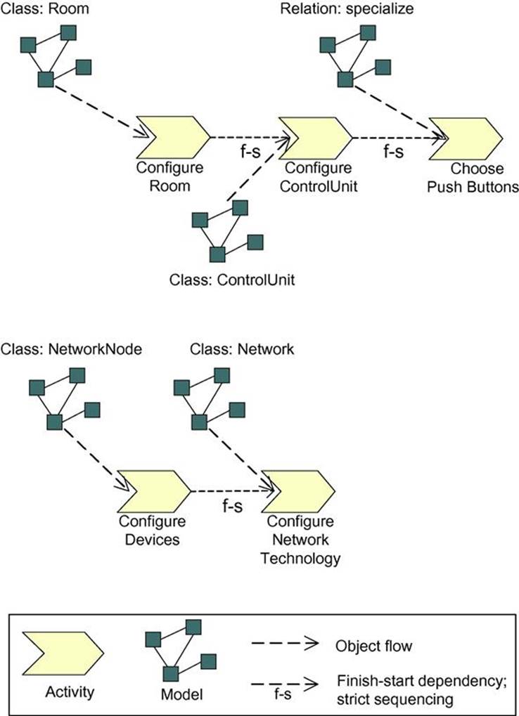
FIGURE 10.5 Dependencies between configuration activities as a process model for the Smarthome example. The dependencies restrict possible orders of activities. In general, the decisions for one configuration activity can be computed from the feature and system model. However, in the current example, only restricting dependencies related to the system model are needed, while dependencies related to the feature model are not. Thus, the features can be configured in an arbitrary order.
Activity. An activity describes a piece of work performed by one process role. An activity consists of one or more atomic elements called steps. Activities represent configuration activities, such as configuring the control unit. A number of classes of the feature model or system model is assigned to each activity. All attributes and relations of these classes are subject to configuration in that activity. For example, for activity Configure ControlUnit the class ControlUnit is assigned, indicated by model Class: ControlUnit. The related decisions are:
• To configure the association regulates to a LightGroup
• To make sure that the ControlUnit is part of a SmartRoom
• And to determine the values of the inherited attributes PowerConsumption and Price
It is important to note that all necessary decisions can be computed from the feature and system model (see Figures 10.3 and 10.4). For an example for computing necessary decisions from a model, refer to the modeling of procedural knowledge in KONWERK (see Hotz and Günter, 2014).7
Model. A model is a specific kind of work product. A work product is anything produced, consumed, or modified by a process. Examples for work products besides a model are documents and source code.
Finish-start. If activity B has a finish-start dependency with respect to activity A, then B can only start after A has finished (strict sequencing, no parallelism). Such dependencies represent dependencies between configuration activities.
The dependencies in Figure 10.5 are the only order aspects; the order of the other configuration activities, especially the acquisition of features, is not fixed, and, thus, must not be modeled. Furthermore, the configuration of a subsystem does not need to be finalized before a next subsystem is configured. Instead, after selecting parts for one subsystem these parts might well be changed due to decisions in the configuration of another subsystem in order to gain an optimal solution. After such changes, other parts have to be updated to get a correct solution. It is common for configuration tasks that a customer changes his requirements during the configuration process of a technical system.
10.6 Characteristics of the Smarthome Model
Compared to the working example introduced in Hotz et al. (2014),8 the Smarthome model covers two additional characteristics of configuration models, which the following subsections summarize:
• The separation of features and realizing components through a feature model and a system model (see Subsection 10.6.1)
• The modeling of a workflow for the configuration process (see Subsection 10.6.2)
10.6.1 Characteristics of the Separation of the Feature and System Model
The feature model is quite simple while the system model is more complex because of the internal structure of the components (e.g., a sensor aggregate which composes sensors). For example, in the feature model, the user determines if light groups should be switchable or dimmable. In the system model, decisions between distinct devices or device categories have to be made to realize this feature. The feature model provides a user view of the system. It can be directly used for the configuration process, by acquiring the desired features from the user. Through the direct connection to the system model, the realizability of the selected features can be ensured by configuring the components directly after the features were selected.
The feature model and the system model can easily be represented with the modeling facilities of a typical configuration system. For example, features can be represented as attributes with Boolean values or with classes and cardinalities. For a detailed description of modeling facilities, refer to Hotz et al. (2014).
10.6.2 Characteristics of the Introduction of a Workflow
The building automation system demonstrates the need of a workflow for structuring configuration activities in complex configuration tasks because the configuration activities depend on each other. For example, it is not possible to start the configuration process with an arbitrarily chosen configuration activity, such as configuring the type of a switch. Furthermore, the order of such configuration activities depends on domain characteristics (such as determining the network technology of a building automation system at the end of the configuration process). Therefore, such dependencies must be represented in the configuration model.
This characteristic distinguishes complex configuration problems from simpler configuration problems that can be solved with other reasoning techniques such as pure constraint processing. A one-step approach (to describe a problem and then to solve it) can’t be followed when solving a complex configuration problem. For complex problems, an approach with several steps (or configuration activities) is required. Each activity involves one or more decisions and a computation of the entailments of these decisions. These again influence the possible values of subsequent decisions. Thus, solving a configuration problem is a sequence of pairs consisting of decision-making and computing influences by reasoning.
Not all configuration systems can represent workflows like those described in this example. Instead the workflow is directly implemented in an application-specific user-interface. For a model-based representation of a workflow, refer to Hotz and Günter (2014).9
10.7 Conclusion
This chapter provided a configuration example that includes a complex model divided in user-visible features, realizing components, and relations between those. The example demonstrated also the need for modeling configuration workflows.
References
1. Czarnecki K, Helsen S, Eisenecker U. Formalizing cardinality-based feature models and their specialization. SoftwareProcess: Improvement and Practice. 2005;10(1):7–29.
2. Hotz L, Günter A. KONWERK. In: Felfernig A, Hotz L, Bagley C, Tiihonen J, eds. Knowledge-based Configuration – From Research to Business Cases. Waltham, MA: Morgan Kaufmann Publishers; 2014:281–295. (Chapter 24).
3. Hotz L, Wolter K, Krebs T, et al. Configuration in Industrial Product Families – The ConIPF Methodology. Berlin: IOS Press; 2006.
4. Hotz L, Felfernig A, Stumptner M, Ryabokon A, Bagley C, Wolter K. Configuration knowledge representation and reasoning. In: Felfernig A, Hotz L, Bagley C, Tiihonen J, eds. Knowledge-based Configuration – From Research to Business Cases. Waltham, MA: Morgan Kaufmann Publishers; 2014:41–72. (Chapter 6).
5. Kang, K., Cohen, S., Hess, J., Novak, W., Peterson, S., 1990. Feature-Oriented Domain Analysis Feasibility Study (FODA). Technical Report CMU/SEI-90-TR-021, Carnegie Mellon University, Software Engineering Institute, Pittsburgh, PA.
6. Wolter, K., 2003. Supporting the orientation and navigation of users in the process of configuring complex products (Master’s thesis). Universität Hamburg, Fachbereich Informatik, Hamburg, Germany (in German: Unterstützung der Orientierung und Navigation von Benutzern im Prozess der Konfiguration von komplexen, variantenreichen Produkten).
1Chapter 6.
2Even though the model demonstrates complex modeling aspects, we base the model on simple assumptions about building automation systems. Further information about such systems can be found in Wolter (2003) and in xinca.com, www.buildingtechnologies.siemens.com, www.kmccontrols.com, highperformancehvac.com.
3www.lonmark.org
4Chapter 6.
5Chapter 6.
6For the SPEM specification see www.omg.org. Tools supporting SPEM are Enterprise Architect (www.sparxsystems.com), Eclipse/SPEM Designer (marketplace.explipse.org), or MagicDraw (www.nomagic.com).
7Chapter 24.
8Chapter 6.
9Chapter 24.
All materials on the site are licensed Creative Commons Attribution-Sharealike 3.0 Unported CC BY-SA 3.0 & GNU Free Documentation License (GFDL)
If you are the copyright holder of any material contained on our site and intend to remove it, please contact our site administrator for approval.
© 2016-2026 All site design rights belong to S.Y.A.