Knowledge-based Configuration: From Research to Business Cases, FIRST EDITION (2014)
Part V. Configuration Environments
Chapter 24. KONWERK
Lothar Hotz and Andreas Günter, HITeC e.V., University of Hamburg, Hamburg, Germany
Abstract
This chapter presents the domain-independent configuration tool KONWERK. KONWERK provides hybrid configuration representation facilities implemented in so-called basic modules. Enhancement modules provide aspects such as modeling of complex requirements or creating spatial configurations. These modules can be used for developing diverse applications.
Keywords
Knowledge-based Configuration; Complex Configuration Models; Procedural Knowledge; Hybrid Configuration; Configurator Applications; Generic Constraints
Acknowledgments
Besides the authors, main contributors for the core modules of KONWERK were Frank Buhr, Bernd Neumann, Manfred Kopisch, and Thomas Vietze. Project partners contributed in enhancement modules and applications.
24.1 Overview
KONWERK1 is a domain-independent hybrid configuration tool developed at the University of Hamburg (Günter, 1995; Hotz et al., 2006). This tool provides basic modules for knowledge representation and reasoning with four different types of knowledge: (1)conceptual knowledge, (2) constraint knowledge, (3) task knowledge (in the following denoted as task description), and (4) procedural knowledge (see Günter and Cunis, 1992). The conceptual knowledge is represented in an ontology. Taxonomic (isA) and compositional (hasParts) relations are available. Restrictions between knowledge base elements are defined using constraints. Task descriptions represent the user requirements by providing a configuration goal. On the basis of procedural knowledge, a default order for configuration decisions can be defined. The configuration process can be structured into several subtasks to guide the user. Different interaction styles can be realized; for example, a configuration wizard that presents decisions one after another or a more flexible process where the user receives guidance about which configuration steps should be taken next. The outcome of a configuration, using KONWERK, is a detailed description of all components and their attribute values.
The basic modules of KONWERK partially served as a blueprint for the commercial configuration tool EngCon (see Krebs, 2014)2 and Hollmann et al. (2000)3. Research activities extended these modules by enhancement modules that support additional aspects of configuration tasks such as resource-based configuration, fuzzy computations, and spatial reasoning.
The remainder of the chapter is organized as follows. In Section 24.2, we provide an overview of the knowledge representation and reasoning supported by KONWERK. Section 24.3 introduces the enhancement modules of KONWERK. Section 24.4 provides insights in the implementation of the tool. Section 24.5 sketches some configurators built with the tool.
24.2 Modeling of the Working Example
In KONWERK, a configuration model consists of concepts and constraints. It represents the configuration knowledge in a component-oriented manner. An ontology-like representation enables the definition of concepts and relations such as parameters, taxonomical, and structural relations. Parameters depict relations between a concept and primitive data types such as numbers, strings, intervals, or sets of those data types. A taxonomical relation depicts a subset relation between two concepts. Structural relations are relations between concepts (in GCSP called connections and in Description Logics roles). An example of a structural relation is the compositional relation (such as hasParts).4 Constraint representations augment this ontological knowledge for defining n-ary relations and algebraic expressions. Especially the strong integration of concepts and constraints enables a combined use of Description Logic services (Baader et al., 2003) and constraint-based reasoning (Mackworth, 1977; Rossi et al., 2006; Tsang, 1993); see also Hotz et al. (2014b)5.
In addition to the ontological and constraint knowledge, procedural knowledge can be used for representing the course of configuration actions that has to be processed during the configuration process. Starting from a task description that represents the requirements that a resulting configuration should fulfill, procedural knowledge enables a declarative representation for ordering configuration activities, combining inference methods, as well as integrating external mechanisms such as simulating the configured system and compiling previously configured software components. The integration of procedural knowledge within a well-defined general configuration process enables the control of the used reasoning techniques, even in conflicting situations (Günter and Hotz, 1995; Hotz et al., 2006).
A configuration model in KONWERK contains concepts (![]() ), conceptual constraints (
), conceptual constraints (![]() ), constraint relations (
), constraint relations (![]() ), and procedural knowledge
), and procedural knowledge ![]() .
.
Concepts. A concept ![]() represents a component type of an application domain. A concept stands for a set of concept instances created during the configuration process. A concept instance represents a component of an application domain. Each
represents a component type of an application domain. A concept stands for a set of concept instances created during the configuration process. A concept instance represents a component of an application domain. Each ![]() has an assigned set of properties
has an assigned set of properties ![]() representing attributes of a component type. Properties related to primitive data types are called parameters, those related to concepts are called structural relations.
representing attributes of a component type. Properties related to primitive data types are called parameters, those related to concepts are called structural relations.
An example of a concept used for the PC-domain (see Hotz et al., 2014b6) represented in the Component Description Language of KONWERK (Hotz, 2009) is:7
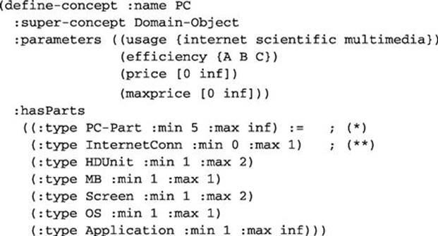
The concept (component type) PC represents a personal computer. The term :super-concept Domain-Object integrates the concept in the specialization hierarchy. Parameters of the concept PC represent attributes of a personal computer, such as usage or efficiency. These parameters have a set of symbols as values (e.g., {A B C}). The parameters price and maxprice have initially the positive infinite range [0 inf]. The structural relation hasParts models the compositional relations of PC to its parts, for example to HDUnit. A set descriptor defines the whole part set with the super-concept of all parts PC-Part and a cardinality (*) as well as a list of part descriptions. A concept and a cardinality defines each part (**).
Conceptual Constraints. Each conceptual constraint ![]() consists of (1) a condition describing a structural situation and (2) a set of constraint calls. The structural situation describes a relational structure of concepts whose instances will be restricted by the constraint calls. Each constraint call is specified by a constraint relation that implements a certain restriction.
consists of (1) a condition describing a structural situation and (2) a set of constraint calls. The structural situation describes a relational structure of concepts whose instances will be restricted by the constraint calls. Each constraint call is specified by a constraint relation that implements a certain restriction.
An example of a conceptual constraint including related concepts is the following:
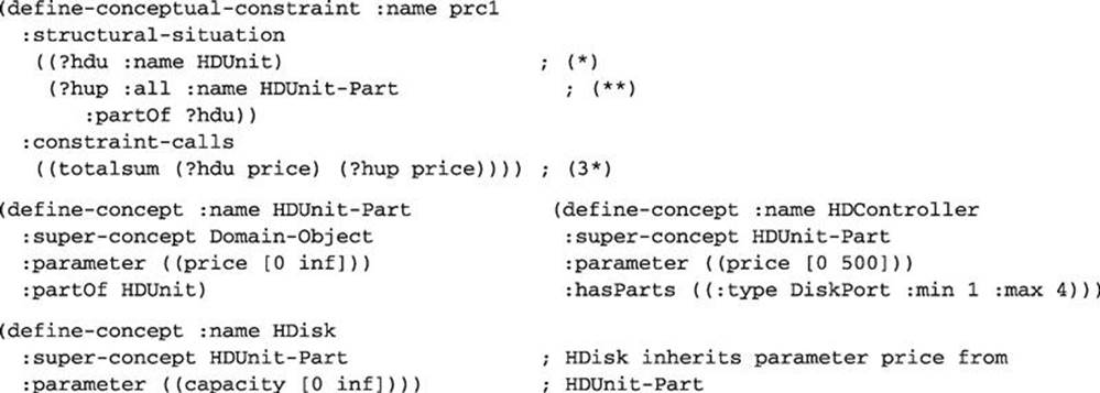
This model chunk defines the pricing constraint prc1 of the working example. This constraint computes the price of a harddisk unit (HDUnit) by summing up the prices of disks (HDisk) and the controllers (HDController). Because both are modeled as parts of a harddisk unit, we can specify HDUnit-Part in the structural situation of the conceptual constraint. This situation describes the condition for the constraint relations to hold. With the variables indicated by “?” particular concept instances identified in the structural situation can be referenced in other conditions or constraint calls. Thus, only if a HDUnit (*) with some HDUnit-Parts (**) exists then the specified constraint-call totalsum (3*) has to be computed. Hereby specific :all constraints (see (**)) are used that are flexible with regard to the number of property variables (e.g., in (3*) (?hup price) represents a set of the parameter price of each found HDisk-Part).
Note that a conceptual constraint looks like a rule (having a condition part, the structural situation, and an action part, the constraint calls), however, the constraint calls do not directly change any properties but instantiate a constraint relation. Thus, the constraint calls of a conceptual constraint increase a constraint net when the structural situation is recognized in the configuration created so far (similar to activation constraints; see Hotz et al., 2014b8).
Constraint Relations. Each constraint relation ![]() consists of a set of constraint pins and an algebraic expression or a relational table relating the constraint pins intensionally or extensionally. A constraint pin is a reference to a property value of a concept instance. Typically, a constraint relation is domain-independent. An example of a constraint relation is the following; it implements the equation summand1 + summand2 = sum:
consists of a set of constraint pins and an algebraic expression or a relational table relating the constraint pins intensionally or extensionally. A constraint pin is a reference to a property value of a concept instance. Typically, a constraint relation is domain-independent. An example of a constraint relation is the following; it implements the equation summand1 + summand2 = sum:
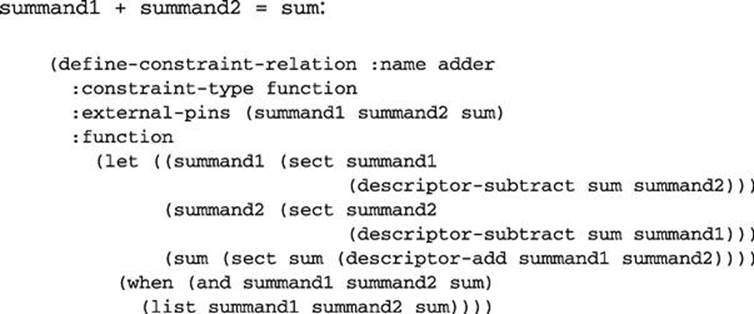
This constraint relation is of type function, which means that a function defines the underlying restriction, not, for example, a relational table. The adder constraint relation takes three arguments (the external pins or constraint variables) and relates them in all directions; each variable is computed according to the values of the other variables (multidirectional constraints). The following example shows the use of the adder constraint relation in the PC domain. The conceptual constraint applies the domain-independent constraint relation adder for computing the price of MB:
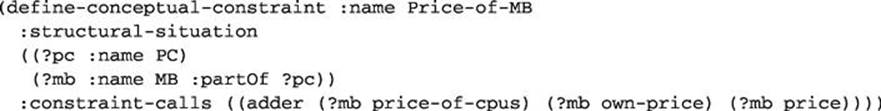
In this example, adder gets the values of the three pins (?mb price-of-cpus), (?mb ownprice), and (?mb price), which are the price of the cpus, the own price of the (?mb MB), and the total price of the MB (see also Figure 24.2). Adder uses the descriptor methodsdescriptor-subtract for subtraction and sect for intersection. Such methods implement set and interval arithmetic for numbers, ranges, or sets of both. For example, the constraint pin (?mb price-of-cpus) might be a set of numbers, say ![]() , (?mb ownprice)the set
, (?mb ownprice)the set ![]() , and (?mb price) might be the range
, and (?mb price) might be the range ![]() . The adder computes the value sets
. The adder computes the value sets ![]() in the order of the given variables. Thus, the range
in the order of the given variables. Thus, the range ![]() is reduced to a set of numbers that represents all possible outcomes of the summation of the values of (?mb price) and (?mb ownprice).
is reduced to a set of numbers that represents all possible outcomes of the summation of the values of (?mb price) and (?mb ownprice).
Besides concepts for representing component types, concept instances are used for representing actual components. However, instances are typically not specified in the configuration model but created by the reasoning system, especially by a task description (or by a structuring configuration step, see later). A task description represents user’s initial requirements (see, e.g., Mittal and Frayman, 1989). Such a description is given in terms of an aggregate, which is to be configured: the goal of the configuration process. Typically, the goal is represented by the root node of the compositional hierarchy. A task description may also define additional requirements such as choices of parts, other aggregates, or prescribed properties. An example of a task description is the following:
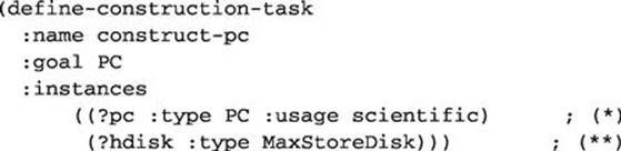
A PC should be constructed for scientific usage (*), which contains at minimum a harddisk of type MaxStoreDisk (**).
Procedural Knowledge. ![]() is a set of strategies. Each strategy is a tuple
is a set of strategies. Each strategy is a tuple ![]() , where
, where ![]() (focus) defines a set of construction steps inferred from the concept definitions
(focus) defines a set of construction steps inferred from the concept definitions ![]() and manages those in an agenda. Each construction step represents onedecision, for example, the setting of a property value. Each construction step is of type
and manages those in an agenda. Each construction step represents onedecision, for example, the setting of a property value. Each construction step is of type ![]() , or
, or ![]() , where the last determines a decision about a relation between concept instances. The structuring configuration step type can be of type top-down structuring or bottom-up structuring. Top-down structuring steps configure structural relations starting from a concept
, where the last determines a decision about a relation between concept instances. The structuring configuration step type can be of type top-down structuring or bottom-up structuring. Top-down structuring steps configure structural relations starting from a concept ![]() to its relative concepts
to its relative concepts ![]() . This relation instantiates new concept instances of
. This relation instantiates new concept instances of ![]() or uses existing ones for establishing the structural relation. For example, for an aggregate (a concept), the parts (the relative concepts) are generated, if they are not already present in the partial configuration. A partial configuration represents all decisions made so far and their implications. Bottom-up structuring steps configure structural relations starting from relative concepts
or uses existing ones for establishing the structural relation. For example, for an aggregate (a concept), the parts (the relative concepts) are generated, if they are not already present in the partial configuration. A partial configuration represents all decisions made so far and their implications. Bottom-up structuring steps configure structural relations starting from relative concepts ![]() to the related concepts
to the related concepts ![]() . This relation instantiates new concept instances of
. This relation instantiates new concept instances of ![]() or uses existing ones for establishing the structural relation; for example, for integrating parts in an aggregate, the aggregate is generated if it is not already present in the partial configuration.
or uses existing ones for establishing the structural relation; for example, for integrating parts in an aggregate, the aggregate is generated if it is not already present in the partial configuration.
In general, a construction step describes a valid property value of a concept instance and how this value can be changed by a value determination method (see later).
A focus (FO) collects construction steps according to a modeled definition, thus, it zooms in on a set of configuration decisions that shall be processed. An example of a focus is:
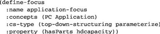
This focus selects top-down structuring for the property hasParts and parameterization for parameter hdcapacity of the concepts PC and Application (i.e., two decisions will be focused).
![]() is a series of selection criteria where each selects a set of construction steps from the set defined by the focus
is a series of selection criteria where each selects a set of construction steps from the set defined by the focus ![]() . Similar to a focus, a selection criterion uses concept and property names as well as construction step types for selecting construction steps.
. Similar to a focus, a selection criterion uses concept and property names as well as construction step types for selecting construction steps.
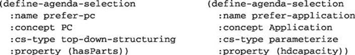
Examples of two selection criteria are the following. Each of these criteria prefers one decision. The prefer-pc selection criteria selects the top-down structuring decision and the prefer-application the parameterization of hdcapacity:
The focus and the selection criteria are combined in a strategy as follows:
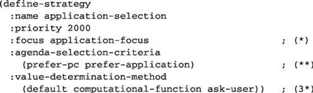
In total, this strategy focuses on decisions that are related to PC and Application by using the application-focus (*). This focus collects two decisions as just described. Those decisions are ordered by the agenda selection criteria prefer-pc and prefer-application; i.e., the hasParts top-down structuring decision is made before the parameterization hdcapacity decision is made (**). The list of value determination methods (3*) is used to compute the configuration steps i.e., first a default value is tried. If it is not defined, a computation function is invoked. If also this value determination method is not able to supply a valid value, the user is asked (“ask-user”). There might be several strategies in a configuration model. The given priorities determine their order. The user interaction (“ask-user”) achieves a dynamic extension of the initially given requirements.
In KONWERK, a configuration problem (task; see also Hotz et al., 2014b9) consists of (1) instances (components) and (2) a configuration model with concepts, constraint definitions, and procedural knowledge. The task description computes the instances. Thus, they are partially instantiated concepts and constitutes the initial partial configuration that represent user’s requirements. The term partially emphasizes the fact that the user typically does not provide a value for each property of the desired instances. The configuration model is used throughout the configuration process to infer values for instance properties and create new instances if needed. A solution ![]() of the problem (a configuration) is a set of instances
of the problem (a configuration) is a set of instances ![]() that are consistent with the concepts, conceptual constraints, and conceptual relations. Additionally, the instances belonging to a solution have to be computed through a configuration process that follows the definitions defined in the procedural knowledge. Furthermore, let
that are consistent with the concepts, conceptual constraints, and conceptual relations. Additionally, the instances belonging to a solution have to be computed through a configuration process that follows the definitions defined in the procedural knowledge. Furthermore, let ![]() be an instance of concept
be an instance of concept ![]() in
in ![]() , then for each structural relation
, then for each structural relation ![]() of
of ![]() there exist one or more instances
there exist one or more instances ![]() (
(![]() ) of concept
) of concept ![]() in
in ![]() according to the cardinality specification in the set descriptor of the relation
according to the cardinality specification in the set descriptor of the relation ![]() . Thus, for each structural relation of an instance, appropriate related instances exist in the solution.
. Thus, for each structural relation of an instance, appropriate related instances exist in the solution.
At the beginning of a configuration process, instances (components) consist of terminal values for requirements and nonterminal values, which represent properties that need to be specified or inferred through reasoning mechanisms. Thus, initial properties have constant values as well as open ranges and qualified sets as values in the beginning. In the final configuration, these values are configured to terminal values such as constants, closed ranges, and fixed sets. Unique identifiers relate instances to each other in such a way that they form the compositional structure or other relations of a configuration.
KONWERK applies (1) ontological services such as inheritance, subset computation, specialization, or top-down and bottom-up structuring to make implicit knowledge in the partial configuration explicit, and (2) constraint propagate that updates property values according to the modeled constraints. These two inference approaches are applied in a cycle that ends when all property values are computed (i.e., are terminal values). Specific structuring steps are responsible for component generation and creation of relational connections between components. These steps compose the configuration. They do this by successively creating new instances as modeled by the structural relations.
All ontological services and constraint propagation change property values of instances contained in the partial configuration. However, this change must only be a reduction of the property values (i.e., the computation of a subset of a property value). This subset computation is defined for all possible property domains including set descriptors of structural relations. By this simple rule, a monotonic behavior of the configuration process is achieved. Also external mechanisms (like simulation or optimization) have to comply with this rule; that is they have to compute subsets of property values. For more on this aspect and a partial logical reconstruction of KONWERK’s representation language (see Schröder et al., 1996; Hotz, 2009).
24.3 Enhancement Modules
To avoid unnecessary complex mechanisms and to provide suitable concepts for different domains, KONWERK provides problem-solving modules that are built on each other. Thus, for the basic four aspects (object-oriented modeling of components, constraints, procedural knowledge, and task description) basic modules are implemented, and for further-reaching methods enhancement modules are developed. Beside others, KONWERK implements the following enhancement modules (see Günter, 1995 for a complete list).
Modeling of complex requirements. The basic representation of requirements are task descriptions containing desired components and attributes. Complex requirements allow the definition of user-related terms that map to needed components. This mapping again can be expressed by using the KONWERK representation facilities such as concept descriptions or constraints. For example, in the XKL10 domain the complex requirements allow us to express that a tourist machine for long-distance flights is desired. From this specification a mapping to needed inventory (such as seats, kitchens, restrooms) will compute an initial partial configuration (Kopisch and Günter, 1992).
Functional modeling and simulation of configured systems. For further testing a configuration, additional modules such as simulation and optimization modules can be included in the configuration process of KONWERK. For such tasks, an enhancement module allows us to model simulation experiments or optimization criteria. The module maps these models to models of a simulation tool like Mathematica, evaluates that model, and writes the results back into the partial configuration of KONWERK (Funke et al., 1994;Sebastian, 1996).
Use of case-based reasoning during configuration. For using previously configured system descriptions, proposals for property values are retrieved from a case base. This kind of reasoning has similarities to recommender systems (Jannach et al., 2010; Ricci et al., 2011, see also Pfitzner, 1993, and Tiihonen et al., 2014)11.
Fuzzy arithmetic. The basic module for concept and constraint reasoning contains an interval arithmetic for computations with ranges of real values. The fuzzy arithmetic enhancement module extends this functionality by introducing modeling and reasoning techniques for fuzzy intervals based on alpha-cuts (Schumann and Schumann, 2008).
Resource-oriented configuration. For representing and computing resource-related aspects, like voltage of batteries, the resource enhancement module allows us to define demanded and provided resources and compute balanced resources for them (Gülden and Hotz, 1997).
Conflict resolution techniques. For recovering the configuration process after a conflict occurs, KONWERK provides various conflict resolution techniques, such as backtracking, model-based resolution, repairing partial configurations, or a dependency-based resolution technique (Hotz and Wolter, 2013). Further information on conflict resolution techniques can be found in Felfernig et al. (2014)12.
24.4 Implementation
For the implementation of the modules diverse techniques are used, such as concept hierarchies to represent domain objects, constraints to represent relations and restrictions on domain objects, and a blackboard architecture to control the configuration process. The underlying assumption is that configuring is an incremental process, where the solution (a configuration) is built successively. Thus, for instance, the constraint net increments i.e., necessary constraints for newly created objects are automatically generated and added to the increasing constraint net.
The build-in interface of KONWERK is designed for knowledge engineers. For example, a knowledge base browser presents all parts of the static knowledge-base (i.e., concepts (see Figure 24.1), constraints, control knowledge, and hierarchies) and the dynamic knowledge-base, which is created during a configuration process. These knowledge-bases include dialog interactions, a constraint-net browser (see Figure 24.2), the elaboration net (an incrementally increasing net of partly configured objects; Figure 24.3), and the agenda (Figure 24.4).
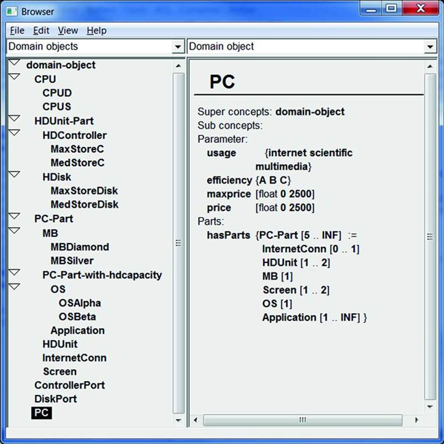
FIGURE 24.1 KONWERK knowledge base browser: specialization hierarchy (left) and one selected concept.
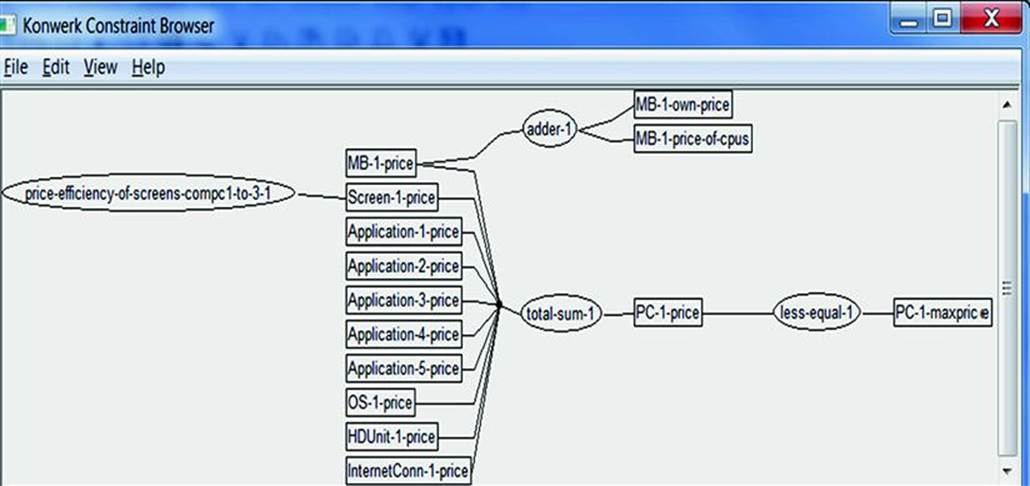
FIGURE 24.2 KONWERK constraint browser: part of the constructed constraint net with two constraints (represented as ellipses) and several variables (represented as boxes). Since CPUs are not yet created in the presented state, there is no constraint for computing the price of the MB.
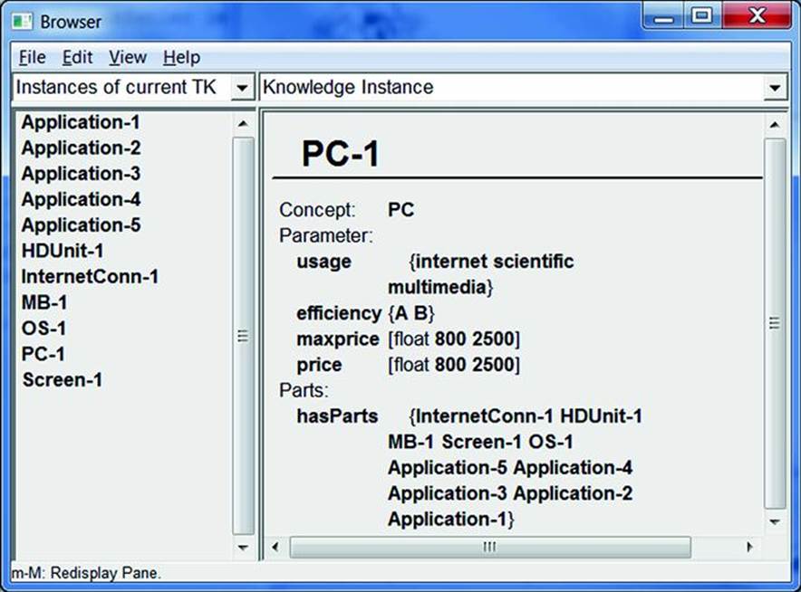
FIGURE 24.3 KONWERK knowledge base browser: partial configuration with instances (left) and one selected instance.
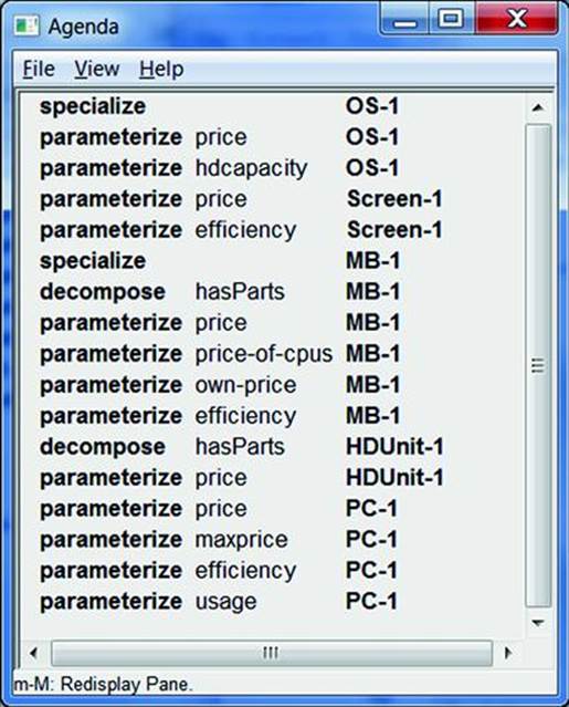
FIGURE 24.4 KONWERK agenda browser: configuration steps are listed with the step type (left), the property (middle), and the instance (right).
KONWERK is written in Common Lisp (Steele, 1984), CLOS (Common Lisp Object System; Keene, 1989, including the Metaobject Protocol; Kiczales et al., 1991), and CLIM (Common Lisp Interface Manager)13 for the user interface.
24.5 Applications
To build an application with KONWERK (i.e., a configurator for a specific domain), first necessary modules are selected from the module set of KONWERK and then appropriate knowledge bases are modeled by using knowledge descriptions provided by each module.
KONWERK was used to implement several applications from different domains (see Cunis et al., 1991; Günter, 1995):
• Selection, arrangement, and layings of friction bearings, especially cylindric radial, axial segment, and axial tilting pad bearings. This application contains a number of conceptual constraints that model mathematical equations related to engine speed or friction power.
• Configuration and dimensioning of jointed shafts in respect to maximal stress and durability. Here constraints compute the torque of operating states, gear, and gearbox output.
• Design of liquid crystals taking, for example, melting points and viscosity into account. The main challenge here is to construct the chemical compound consisting of various atoms.
• Configuration of passenger cabins in vehicle aircrafts; see Figure 24.5. This application shows how spatial relations can be included in the configuration task (Kopisch and Günter, 1992).
• Analog/digital circuits containing functional and algorithmic blocks, signals, and relationships between them. KONWERK supports the user in defining important system parameters such as sampling frequencies, bit widths, or the type of applicable analog-to-digital converters (Oehler, 2000; Oehler et al., 2002).
• Configuration of elevators according to the traditional VT-domain14. Here an elevator is configured consisting of hoist-way, car assembly, drive, and so on (Kühn, 2000; Marcus et al., 1987).
• Building automation systems that allow the concrete representation of features and realizing components (see Wolter, 2003; Hotz and Wolter, 2014)15.
• Applications in software product lines where feature models (see Hotz et al., 2014b16) are coupled with component models (Hotz et al., 2006).
• Constructing a scene interpretation from observed objects in a video or image. An example is a video camera that is installed above a table and observes a tabletop. Human agents place dishes and other objects onto the table, for example, to cover a dinner-for-two. It is the task of the scene interpretation system (the configurator) to generate high-level interpretations such as “place-cover” or “lay-dinner-table-for-two” (see Hotz and Neumann, 2005, and Figure 24.6).
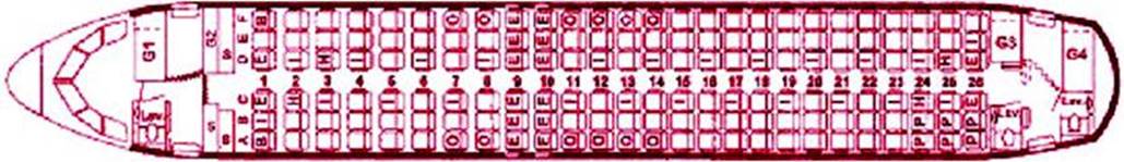
FIGURE 24.5 The cabin-layout configurator XKL, which allows the placement of cabin equipment like seats, kitchens, toilettes in view of customer wishes, technical constraints, legal constraints, and optimality criteria. This application mainly considered configuration with spatial aspects.
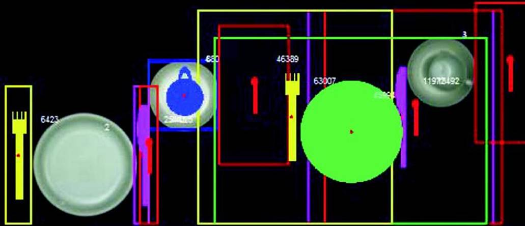
FIGURE 24.6 Example of a scene interpretation constructed with KONWERK. Gray observed objects (one plate, two saucers, and one cup) and iconified hypothesized objects with possible spatial positions computed by component and constraint models describing dish-layouts. Taken from Hotz and Neumann (2005).
The heterogeneity of the considered applications, which include several of the specified aspects, ensure the usability of KONWERK for a wide range of application problems.
24.6 Conclusion
This chapter provides an overview of the hybrid configuration system KONWERK. By combining several knowledge representation and reasoning techniques, KONWERK can be used for complex configuration applications. Experiences gained with KONWERK can be summarized as: Quick prototype creation, high acceptance of the knowledge base, and no application-specific user interface.
References
1. Baader F, Calvanese D, McGuinness DL, Nardi D, Patel-Schneider PF, eds. The Description Logic Handbook: Theory, Implementation, and Applications. New York, NY: Cambridge University Press; 2003.
2. Informatik-Fachberichte vol. 266. Cunis R, Günter A, Strecker H, eds. The PLAKON-Book. London: Springer; 1991; (in German: Das PLAKON-Buch).
3. Felfernig A, Reiterer S, Reinfrank F, Ninaus G, Jeran M. Conflict detection & diagnosis in configuration. In: Felfernig A, Hotz L, Bagley C, Tiihonen J, eds. Knowledge-based Configuration – From Research to Business Cases. Waltham, MA: Morgan Kaufmann Publishers; 2014:73–87. (Chapter 7).
4. Funke B, Müller K, Sebastian H-J, Thaerigen M. Innovative design by integration of expert system technology with multi-criteria decision making and fuzzy systems. In: Moving Towards Expert Systems Globally in the 21st Century, 2nd World Congress on Expert Systems. Lisbon, Portugal: Cognizant Communication Offices; 1994:263–272.
5. Gülden, O., Hotz, L., 1997. Integrating resource-oriented and structure-oriented configuration with KONWERK. In: 11th Workshop Planen und Konfigurieren (PuK-97) im Rahmen der 4. Deutschen Tagung Wissensbasierte Systeme (XPS-97). Bad Honef.
6. Günter A. Knowledge-based Configuration (Wissensbasiertes Konfigurieren). St. Augustin, Germany: Infix; 1995; (in German).
7. Günter A, Cunis R. Flexible control in expert systems for construction tasks. Journal of Applied Intelligence. 1992;2(4):369–385.
8. Günter A, Hotz L. Conflict resolution with knowledge-based backtracking and repair-statement. In: Günter A, ed. Wissensbasiertes Konfigurieren. Infix, St. Augustin 1995:181–192. (in German: Auflösung von Konfigurationskonflikten mit Wissensbasiertem Backtracking und Reparaturanweisungen).
9. Hollmann O, Wagner T, Günter A. EngCon: a flexible domain-independent configuration engine. In: 14th European Conference on Artificial Intelligence (ECAI 2000), Configuration Workshop, Berlin, Germany. 2000;94–96.
10. Hotz, L., 2009. Frame-based Knowledge Representation for Configuration, Analysis, and Diagnoses of Technical Systems. Dissertation, University of Hamburg, Germany (in German: Frame-basierte Wissensrepräsentation für Konfigurierung, Analyse und Diagnose technischer Systems).
11. Hotz L, Neumann B. Scene interpretation as a configuration task. Künstliche Intelligenz. 2005;3:59–65.
12. Hotz L, Wolter K. Beyond physical product configuration – configuration in unusual domains. AI Communications. 2013;26(1):39–66.
13. Hotz L, Wolter K. Smarthome configuration model. In: Felfernig A, Hotz L, Bagley C, Tiihonen J, eds. Knowledge-based Configuration – From Research to Business Cases. Waltham, MA: Morgan Kaufmann Publishers; 2014:121–135. (Chapter 10).
14. Hotz L, Wolter K, Krebs T, et al. Configuration in Industrial Product Families – The ConIPF Methodology. Berlin, Germany: IOS Press; 2006.
15. Hotz L, Felfernig A, Günter A, Tiihonen J. A short history of configuration technologies. In: Felfernig A, Hotz L, Bagley C, Tiihonen J, eds. Knowledge-based Configuration – From Research to Business Cases. Waltham, MA: Morgan Kaufmann Publishers; 2014a:9–19. (Chapter 2).
16. Hotz L, Felfernig A, Stumptner M, Ryabokon A, Bagley C, Wolter K. Configuration knowledge representation and reasoning. In: Felfernig A, Hotz L, Bagley C, Tiihonen J, eds. Knowledge-based Configuration – From Research to Business Cases. Waltham, MA: Morgan Kaufmann Publishers; 2014b:41–72. (Chapter 6).
17. Jannach D, Zanker M, Felfernig A, Friedrich G. Recommender Systems: An Introduction. Cambridge University Press 2010.
18. Keene SE. Object-Oriented Programming in Common Lisp: A Programmer’s Guide to CLOS. Boston, MA: Addison-Wesley; 1989.
19. Kiczales J, Bobrow DG, des Rivieres J. The Art of the Metaobject Protocol. Cambridge, MA: MIT Press; 1991.
20. Kopisch M, Günter A. Configuration of a passenger aircraft cabin based on conceptual hierarchy, constraints and flexible control. In: Belli F, Radermacher F, eds. Industrial and Engineering Applications of Artificial Intelligence and Expert Systems (IEA/AIE-92). Paderborn: Springer; 1992:421–430. Lecture Notes in Computer Science vol. 604.
21. Krebs T. encoway. In: Felfernig A, Hotz L, Bagley C, Tiihonen J, eds. Knowledge-based Configuration – From Research to Business Cases. Waltham, MA: Morgan Kaufmann Publishers; 2014:271–279. (Chapter 23).
22. Kühn C. Modeling structure and behaviour for knowledge based software configuration. In: Sauer J, ed. 14th Workshop, New Results in Planning, Scheduling and Design (PuK2000), Berlin, Germany. 2000.
23. Mackworth A. Consistency in networks of relations. Artificial Intelligence. 1977;8(1):99–118.
24. Marcus S, Stout J, McDermott J. VT: an expert elevator designer that uses knowledge-based backtracking. AI Magazine. 1987;8(4):41–58.
25. Mittal S, Frayman F. Towards a generic model of configuration tasks. In: 11th International Joint Conference on Artificial Intelligence (IJCAI-89), vol 2, Detroit, MI. 1989:1395–1401.
26. Neumann B. Configuration expert systems: a case study and tutorial. In: Bunke HO, ed. Proceedings of the 1988 SGAICO Conference on Artificial Intelligence in Manufacturing, Assembly, and Robotics Oldenbourg, Munich. 1988;27–68.
27. Oehler, P., 2000. Knowledge-based construction of mixed analog/digital systems. Dissertation, J.W. Goethe-Universitüt, Frankfurt, Germany (in German: Wissensbasierte Konstruktion gemischt analog/digitaler Systeme).
28. Oehler P, Grimm C, Waldschmidt K. A methodology for system-level synthesis of mixed-signal applications. IEEE Transactions on Very Large Scale Integration (VLSI) Systems. 2002;10(6):935–942.
29. Pfitzner K. Case-based configuration of technical systems (Fallbasierte Konfigurierung technischer Systeme). Künstliche Intelligenz. 1993;7/93:24–30.
30. Ricci F, Rokach L, Shapira B, Kantor P. Recommender Systems Handbook. Springer 2011.
31. Foundations of Artificial Intelligence . Rossi F, vanBeek P, Walsh T, eds. Handbook of constraint programming. Amsterdam, The Netherlands: Elsevier; 2006.
32. Schröder C, Möller R, Lutz C. A partial logical reconstruction of PLAKON/KONWERK. In: Baader F, Bürckert H-J, Günther A, Nutt W, eds. Proceedings of the Workshop on Knowledge Representation and Configuration WRKP’96 No D-96-04 in DFKI Documents. 1996:55–64.
33. Schumann S, Schumann O. Modeling uncertainty with the configuration tool KONWERK. In: Steinmuller J, Langner H, Ritter M, Zeidler J, eds. 15 Years Artificial Intelligence at the TU Chemnitz. TU Chemnitz: Chemnitzer Informatik-Berichte; 2008:33–44.
34. Sebastian H-J. Intelligent systems for configuration problems. In: Sebastian H-J, Antonsson E, eds. Fuzzy Sets in Engineering Design and Configuration. US: Springer; 1996:89–232. International Series in Intelligent Technologies vol. 9.
35. Steele GLJ. COMMON LISP: The Language. Bedford, MA: Digital Press; 1984.
36. Tiihonen J, Felfernig A, Mandl M. Personalized configuration. In: Felfernig A, Hotz L, Bagley C, Tiihonen J, eds. Knowledge-based Configuration – From Research to Business Cases. Waltham, MA: Morgan Kaufmann Publishers; 2014:167–179. (Chapter 13).
37. Tsang E. Foundations of Constraint Satisfaction. London, San Diego, New York: Academic Press; 1993.
38. Wolter, K., 2003. Supporting the orientation and navigation of users in the process of configuring complex products. Master’s thesis, Universität Hamburg, Fachbereich Informatik, Hamburg (in German: Unterstützung der Orientierung und Navigation von Benutzern im Prozess der Konfiguration von komplexen, variantenreichen Produkten).
1KONWERK (Konfigurierungs-Werkzeug, Configuration Tool) was developed in the German government-funded research project Prokon.
2Chapter 23.
3KONWERK itself is a successor of PLAKON; see Hotz et al. (2014a, Chapter 2) and Neumann (1988).
4See Hotz et al. (2014b, Chapter 6) for a detailed discussion of alternative configuration knowledge representations.
5Chapter 6.
6Chapter 6.
7“;” denote comments.
8Chapter 6.
9Chapter 6.
10An eXpert system for cabin (English for Kabine) Layout that supports the configuration of a passenger cabin for an AIRBUS A340; see also Figure 24.5.
11Chapter 13.
12Chapter 7.
13bauhh.dyndns.org.
14Vertical Transportation.
15Chapter 10.
16Chapter 6.
All materials on the site are licensed Creative Commons Attribution-Sharealike 3.0 Unported CC BY-SA 3.0 & GNU Free Documentation License (GFDL)
If you are the copyright holder of any material contained on our site and intend to remove it, please contact our site administrator for approval.
© 2016-2026 All site design rights belong to S.Y.A.