iOS Drawing: Practical UIKit Solutions (2014)
Chapter 5. Paths in Depth
Exposing path internals amps up the way you work with the UIBezierPath class. In particular, it enables you to leverage the CGPathElement data structures stored in each instance’s underlying CGPath to produce solutions for many common iOS drawing challenges. Want to place objects along a path’s curves? Want to divide the path into subpaths and color them individually? Element-based solutions enable you to do that.
This chapter starts off with rather a lot of didactic implementation details. It finishes with solutions that leverage these implementations, creating compelling drawing results for your iOS projects.
Path Elements
The UIBezierPath class supports three kinds of Bezier elements: line segments, quadratic curves, and cubic curves, which you see in Figure 5-1. Each element represents one of five operations that describe the way the path is laid out:
![]() kCGPathElementMoveToPoint—This element sets the path’s position to a new location but does not add any lines or curves.
kCGPathElementMoveToPoint—This element sets the path’s position to a new location but does not add any lines or curves.
![]() kCGPathElementAddLineToPoint—This element adds a line segment from the previous point to the element’s location. You see a line segment in Figure 5-1, in the top drawing.
kCGPathElementAddLineToPoint—This element adds a line segment from the previous point to the element’s location. You see a line segment in Figure 5-1, in the top drawing.
![]() kCGPathElementAddQuadCurveToPoint—This element adds a quadratic curve from the previous point to the element’s location. The middle drawing in Figure 5-1 is built with a quad curve, using a single control point.
kCGPathElementAddQuadCurveToPoint—This element adds a quadratic curve from the previous point to the element’s location. The middle drawing in Figure 5-1 is built with a quad curve, using a single control point.
![]() kCGPathElementAddCurveToPoint—This element adds a cubic curve from the previous point to the element’s location. The bottom drawing in Figure 5-1 shows a cubic curve, with its two control points.
kCGPathElementAddCurveToPoint—This element adds a cubic curve from the previous point to the element’s location. The bottom drawing in Figure 5-1 shows a cubic curve, with its two control points.
• kCGPathElementCloseSubpath—This element closes the subpath, drawing a line from the current point to the start of the most recent subpath. This start location is always set using a “move to point” element.
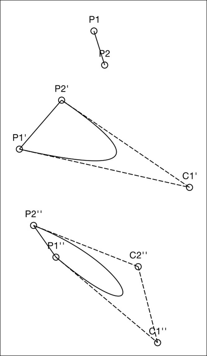
Figure 5-1 You can construct Bezier paths from lines (top), quadratic curves with a single control point (middle), and cubic curves with two control points (bottom).
Each CGPathElement stores an element type (one of the five types you just saw) and an array of CGPoint items:
struct CGPathElement {
CGPathElementType type;
CGPoint *points;
};
An element’s points array may store zero, one, two, or three points. The number depends on the element’s role in the path. Close-path elements don’t define any points. The move-to-point and line-to-point elements use one, which specifies the destination. The destination tells the element where to move or where to add a line.
Both quad and cubic curves require control points in addition to the destination. A quad curve stores a destination and one control point. A cubic curve stores a destination and two control points. What’s more, the order of these points varies by the point type.
Wrapping these path elements in an Objective-C class, as shown in Listing 5-1, simplifies their use. This class hides the intricacies of the point array with its implementation details, such as which item is the destination point and which items are the control points. Each element-based object expresses a consistent set of properties, forming a stepping-stone for many handy UIBezierPath utilities.
Listing 5-1 An Objective-C Wrapper for CGPathElement
#define NULLPOINT CGRectNull.origin
@interface BezierElement : NSObject <NSCopying>
@property (nonatomic, assign) CGPathElementType elementType;
@property (nonatomic, assign) CGPoint point;
@property (nonatomic, assign) CGPoint controlPoint1;
@property (nonatomic, assign) CGPoint controlPoint2;
@end
@implementation BezierElement
- (instancetype) init
{
self = [super init];
if (self)
{
_elementType = kCGPathElementMoveToPoint;
_point = NULLPOINT;
_controlPoint1 = NULLPOINT;
_controlPoint2 = NULLPOINT;
}
return self;
}
// Create a BezierElement object that represents
// the data stored in the passed element
+ (instancetype) elementWithPathElement:
(CGPathElement) element
{
BezierElement *newElement = [[self alloc] init];
newElement.elementType = element.type;
switch (newElement.elementType)
{
case kCGPathElementCloseSubpath:
break;
case kCGPathElementMoveToPoint:
case kCGPathElementAddLineToPoint:
{
newElement.point = element.points[0];
break;
}
case kCGPathElementAddQuadCurveToPoint:
{
newElement.point = element.points[1];
newElement.controlPoint1 = element.points[0];
break;
}
case kCGPathElementAddCurveToPoint:
{
newElement.point = element.points[2];
newElement.controlPoint1 = element.points[0];
newElement.controlPoint2 = element.points[1];
break;
}
default:
break;
}
return newElement;
}
Converting Bezier Paths into Element Arrays
Quartz’s CGPathApply() function iterates across all the elements that comprise a path. As Listing 5-2 demonstrates, this enables you to convert a UIBezierPath into an array of its components. This listing converts and collects those path elements along the way. The result is anNSArray of Objective-C BezierElement objects, each representing an original path element.
Listing 5-2 Extracting Element Arrays
// Convert one element to BezierElement and save to array
void GetBezierElements(void *info, const CGPathElement *element)
{
NSMutableArray *bezierElements =
(__bridge NSMutableArray *)info;
if (element)
[bezierElements addObject:
[BezierElement elementWithPathElement:*element]];
}
// Retrieve array of component elements
- (NSArray *) elements
{
NSMutableArray *elements = [NSMutableArray array];
CGPathApply(self.CGPath, (__bridge void *)elements,
GetBezierElements);
return elements;
}
Extracting elements from Bezier paths enables you to perform geometric operations on the components. Afterward, you rebuild Bezier paths from the updated components. Listing 5-3 shows this reassembly. Its BezierPathWithElements() constructor function creates a new path and then iteratively calls addToPath: on each element. As you can see from the implementation, this method applies each element’s point values and type to build the new path.
Listing 5-3 Reassembling Bezier Paths
// Construct a Bezier path from an element array
UIBezierPath *BezierPathWithElements(NSArray *elements)
{
UIBezierPath *path = [UIBezierPath bezierPath];
for (BezierElement *element in elements)
[element addToPath:path];
return path;
}
// This is a BezierElement method. The element
// adds itself to the path passed as the argument
- (void) addToPath: (UIBezierPath *) path
{
switch (self.elementType)
{
case kCGPathElementCloseSubpath:
[path closePath];
break;
case kCGPathElementMoveToPoint:
[path moveToPoint:self.point];
break;
case kCGPathElementAddLineToPoint:
[path addLineToPoint:self.point];
break;
case kCGPathElementAddQuadCurveToPoint:
[path addQuadCurveToPoint:self.point
controlPoint:self.controlPoint1];
break;
case kCGPathElementAddCurveToPoint:
[path addCurveToPoint:self.point
controlPoint1:self.controlPoint1
controlPoint2:self.controlPoint2];
break;
default:
break;
}
}
Legal and Illegal Paths
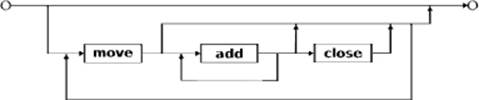
A legal path always begins with a move operation followed by a series of lines and curves, and it ends with an optional close operation. You repeat as desired. Here’s a summary of what makes a legal path:
path :- ø | {move • (add)* • {add • close | ø}}*
A path can be entirely empty, like this:
UIBezierPath *path = [UIBezierPath bezierPath]
Or a path can consist of a move operation followed by zero or more add elements. The following snippet creates a path by moving to point p1, adds a quad curve from point p1 to point p2 (using control point c1), and then closes that path with a line from point p2 to point p1:
[path moveToPoint:p1];
[path addQuadCurveToPoint:p2 controlPoint:c1];
[path closePath];
Figure 5-1 (middle) shows an example of what this path with its move, curve, and close elements might look like when drawn.
A close element, if used, should always follow an add line or add curve element. Here, it tells the path to add a line from the current point (p2) to the first point (p1).
Path State
Bezier operations depend on the path storing (or, more accurately, being able to derive) two key pieces of state. These are where the first point of the path was placed and where the current point of the path is placed.
For example, when you add a line to a point, the full line segment is [path’s current point, new requested point]. When you close a path, the segment you create is [path’s current point, path’s first point]. These values are established as the path progresses. At each add operation, the new requested point becomes the current point:
[path moveToPoint:p1]; // First and current points are p1
[path addQuadCurveToPoint:p2
controlPoint:c1]; // Current point is p2
[path closePath]; // No current point
These state items are important because each add request requires at least one extra state that isn’t specified by the method invocation. You don’t say addLineFrom:to:. You either add a line or curve to some point or closePath. The path understands where the current point is and where the first point was. If it cannot establish these states, any new operation that refers to them is illegal.
Just because Xcode compiles your code without complaint doesn’t mean the path you’re building is legal. Example 5-1 shows an illegal path construction sequence. It starts by closing a path and then adds a quad curve.
Example 5-1 Constructing a Path with Multiple Closed Subpaths
UIBezierPath *path = [UIBezierPath bezierPath;
[p closePath];
[p addQuadCurveToPoint:p1 controlPoint:p2];
[p stroke];
Executing this code produces the console errors you see here:
<Error>: void CGPathCloseSubpath(CGMutablePathRef): no current point.
<Error>: void CGPathAddQuadCurveToPoint(CGMutablePathRef,
const CGAffineTransform *, CGFloat, CGFloat, CGFloat, CGFloat):
no current point.
If you cut and paste this into a project, you’ll discover that no exceptions are raised, and the app continues running. The path cannot be drawn, however. The current context remains unchanged, even after you apply the stroke command in the last line of Example 5-1.
Although this particular example demonstrates a robustness of the underlying drawing system, not all operations are so lucky. Some drawing errors can raise exceptions that interfere with application execution. Apple’s buggy path-reversing bezierPathByReversingPath method is one example of a method that has crashed apps on me.
Compound Paths
The UIBezierPath class enables you to add multiple paths together to build compound paths. As you can see in Figure 5-2, a path need not be continuous. It can contain multiple disjoint sections. Figure 5-2’s path includes six subpaths, consisting of the four outer parts of the letters and the two holes (inside the p and a).
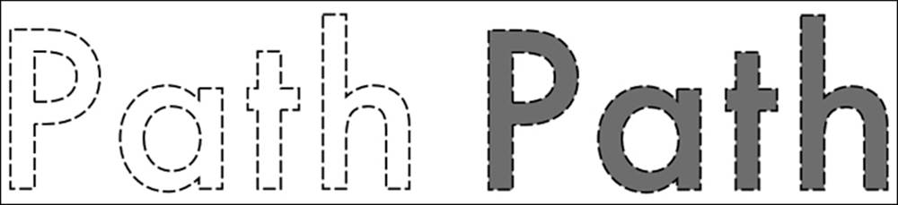
Figure 5-2 This compound path consists of six subpaths.
Consider an example of creating multiple subpaths in code. Example 5-2 builds a new path through a series of move, add, and close statements. The example uses two distinct move–add–close sequences, establishing a single path with two closed subpaths.
Example 5-2 Constructing a Path with Multiple Closed Subpaths
UIBezierPath *path = [UIBezierPath bezierPath];
// Begin subpath 1
[path moveToPoint:p1];
[path addLineToPoint:p2];
[path addCurveToPoint:p3 controlPoint1:p4 controlPoint2:p5];
[path closePath];
// Begin subpath 2
[path moveToPoint:p6];
[path addQuadCurveToPoint:p7 controlPoint:p8];
[path addQuadCurveToPoint:p9 controlPoint:p0];
[path closePath];
You can append entire paths by using appendPath:. This option is particularly helpful when you are assembling drawing items from ready-built path components, as is done in Example 5-3.
Example 5-3 Constructing a Path with Multiple Closed Subpaths
UIBezierPath *path = [UIBezierPath bezierPath];
[path appendPath:[UIBezierPath
bezierPathWithRect:rect1]];
[path appendPath:[UIBezierPath
bezierPathWithOvalInRect:rect2]];
Compound paths enable you to build complex drawings with holes and standalone elements. In Figure 5-2, you saw a path with six distinct subpaths: the outer hulls of each letter and the holes in the p and a. The even/odd rule introduced in Chapter 4 ensures that the interiors of these two holes remain empty when you fill the path, as shown in Figure 5-2 (bottom).
Math Behind the Path
As you’ve now discovered, the UIBezierPath class supports three kinds of Bezier segments: linear, quadratic, and cubic. Each of these participates in the class to create complex shapes for UIKit and Quartz drawing routines. Retrieving component lines and curves enables you to calculate their lengths and interpolate along their paths. With this knowledge, you can apply drawing functions at computed points, as shown in Figure 5-3.
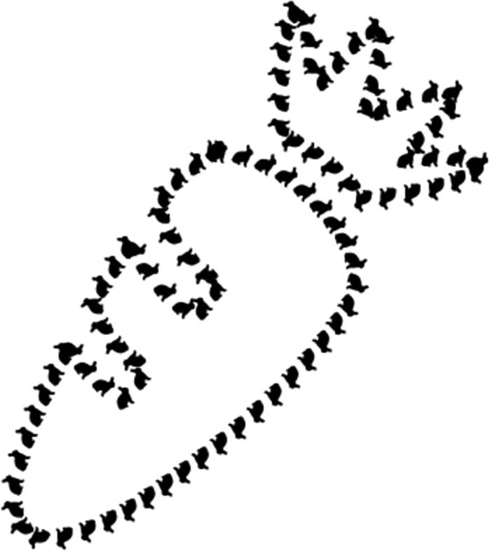
Figure 5-3 This carrot is drawn with Bezier bunny images placed at equal intervals along the carrot path.
Unfortunately, the CGPathElement structure doesn’t offer you much to work with. It provides an element type that might be one of the following: move to point, add line to point, add curve to point, add quad curve to point, or close path. So how do you calculate the intermediate points between one point and the next?
With linear items, it’s easy. You calculate the vector from one point to the next and scale it to the percentage of progress. Listing 5-4 shows an interpolating function.
Listing 5-4 Interpolating on Line Segments
// Interpolate between p1 and p2
CGPoint InterpolateLineSegment(
CGPoint p1, CGPoint p2,
CGFloat percent, CGPoint *slope)
{
CGFloat dx = p2.x - p1.x;
CGFloat dy = p2.y - p1.y;
if (slope)
*slope = CGPointMake(dx, dy);
CGFloat px = p1.x + dx * percent;
CGFloat py = p1.y + dy * percent;
return CGPointMake(px, py);
}
But given a curve, how do you interpolate? Fortunately, you can apply the same curve math that the UIBezierPath class uses. Listing 5-5 offers functions for cubic (two control points) and quadratic (one control point) interpolation, calculating those values. You supply the percentage of progress (from 0 to 1), the start value, the end value, and the one or two control values. The functions return the interpolated points.
Listing 5-5 Interpolating Bezier Curves
// Calculate Cubic curve
CGFloat CubicBezier(CGFloat t, CGFloat start,
CGFloat c1, CGFloat c2, CGFloat end)
{
CGFloat t_ = (1.0 - t);
CGFloat tt_ = t_ * t_;
CGFloat ttt_ = t_ * t_ * t_;
CGFloat tt = t * t;
CGFloat ttt = t * t * t;
return start * ttt_
+ 3.0 * c1 * tt_ * t
+ 3.0 * c2 * t_ * tt
+ end * ttt;
}
// Calculate quad curve
CGFloat QuadBezier(CGFloat t, CGFloat start,
CGFloat c1, CGFloat end)
{
CGFloat t_ = (1.0 - t);
CGFloat tt_ = t_ * t_;
CGFloat tt = t * t;
return start * tt_
+ 2.0 * c1 * t_ * t
+ end * tt;
}
// Interpolate points on a cubic curve
CGPoint CubicBezierPoint(CGFloat t, CGPoint start,
CGPoint c1, CGPoint c2, CGPoint end)
{
CGPoint result;
result.x = CubicBezier(t, start.x, c1.x, c2.x, end.x);
result.y = CubicBezier(t, start.y, c1.y, c2.y, end.y);
return result;
}
// Interpolate points on a quad curve
CGPoint QuadBezierPoint(CGFloat t,
CGPoint start, CGPoint c1, CGPoint end)
{
CGPoint result;
result.x = QuadBezier(t, start.x, c1.x, end.x);
result.y = QuadBezier(t, start.y, c1.y, end.y);
return result;
}
Calculating Path Distance
Before you can say “move 35% along a path,” you must be able to evaluate a path’s length. That’s what the functions and method in Listing 5-6 provide for you. They return a value, in points, that represents the path’s extent at its current scale.
The pathLength method calculates a Bezier path’s length by iteratively applying the ElementDistanceFromPoint() function to each of its elements. This function uses path state (specifically the current and first points) to return the distance for each successive path element.
This depends on three functions that calculate linear distance and distance along a cubic or a quad Bezier curve. Curves are sampled N times; you specify what that sampling number is. In this listing, it is six. This turns out to be a decent approximation for most curves. Some implementations reduce that number to three to increase the overall efficiency. The trade-off is this: The fewer samples you take, the less accurate your distance measures will be.
Figure 5-4 shows a real-world example, where I calculated the differences between the three-point and six-point values. The results for each curve equal the sum of the linear distances between the sample points. In this case, the three-point sample was approximately 6% shorter than the six-point sample. As the curvature increased, so did the sampling differences, reaching up to 10%–15% for highly curved cubic sections.
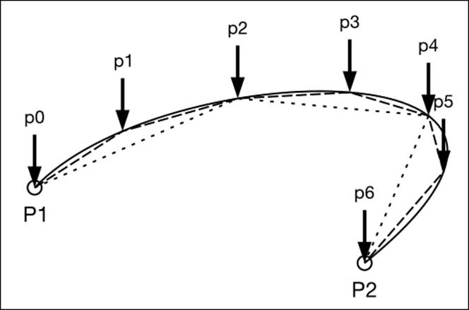
Figure 5-4 As the number of sample segments increases, path length measurements grow more accurate. The solid line is the original curve. The dashed line uses six samples to approximate the curve. The dotted line uses three samples.
Of course, there are trade-offs. As you raise the number of samples, the time to calculate the curve approximation increases, as does the accuracy of the measure—to a point. Too many samples, and you’re just spinning your CPU’s wheels (metaphorically), without substantial mathematical improvement in your measurement.
Listing 5-6 Element Distance
// Distance from p1 to p2
CGFloat PointDistanceFromPoint(CGPoint p1, CGPoint p2)
{
CGFloat dx = p2.x - p1.x;
CGFloat dy = p2.y - p1.y;
return sqrt(dx*dx + dy*dy);
}
// How many points to interpolate
#define NUMBER_OF_BEZIER_SAMPLES 6
// Cubic length
float CubicBezierLength(
CGPoint start, CGPoint c1, CGPoint c2, CGPoint end)
{
int steps = NUMBER_OF_BEZIER_SAMPLES;
CGPoint current;
CGPoint previous;
float length = 0.0;
for (int i = 0; i <= steps; i++)
{
float t = (float) i / (float) steps;
current = CubicBezierPoint(t, start, c1, c2, end);
if (i > 0)
length += PointDistanceFromPoint(
current, previous);
previous = current;
}
return length;
}
// Quad length
float QuadBezierLength(
CGPoint start, CGPoint c1, CGPoint end)
{
int steps = NUMBER_OF_BEZIER_SAMPLES;
CGPoint current;
CGPoint previous;
float length = 0.0;
for (int i = 0; i <= steps; i++)
{
float t = (float) i / (float) steps;
current = QuadBezierPoint(t, start, c1, end);
if (i > 0)
length += PointDistanceFromPoint(
current, previous);
previous = current;
}
return length;
}
// Calculate element-to-element distance
CGFloat ElementDistanceFromPoint(
BezierElement *element, CGPoint point, CGPoint startPoint)
{
CGFloat distance = 0.0f;
switch (element.elementType)
{
case kCGPathElementMoveToPoint:
return 0.0f;
case kCGPathElementCloseSubpath:
return PointDistanceFromPoint(point, startPoint);
case kCGPathElementAddLineToPoint:
return PointDistanceFromPoint(point, element.point);
case kCGPathElementAddCurveToPoint:
return CubicBezierLength(point,
element.controlPoint1, element.controlPoint2,
element.point);
case kCGPathElementAddQuadCurveToPoint:
return QuadBezierLength(point, element.controlPoint1,
element.point);
}
return distance;
}
// Bezier pathLength property
- (CGFloat) pathLength
{
NSArray *elements = self.elements;
CGPoint current = NULLPOINT;
CGPoint firstPoint = NULLPOINT;
float totalPointLength = 0.0f;
for (BezierElement *element in elements)
{
totalPointLength += ElementDistanceFromPoint(
element, current, firstPoint);
if (element.elementType == kCGPathElementMoveToPoint)
firstPoint = element.point;
else if (element.elementType ==
kCGPathElementCloseSubpath)
firstPoint = NULLPOINT;
if (element.elementType != kCGPathElementCloseSubpath)
current = element.point;
}
return totalPointLength;
}
Interpolating Paths
Listing 5-7 enables you to interpolate a path instance to find a point that’s some percentage along it. The code is extensive because of two things. First, all cases must be considered—linear, cubic curves, and quadratic curves. That involves a bunch of switch statements to consider and calculate each possibility.
Second, this method returns an optional slope—that’s the CGPoint address passed as the last parameter. Calculating a slope requires about as much code as calculating the actual point in question. You want a slope value because it expresses the tangent to the path’s curve at the point in question. This enables you to do things like have all your shapes orient themselves toward the inside of the curve, as you saw in Figure 5-3.
Note that reversing the path reverses the slope. Items at each point that used to represent the tangent on the outside of the curve flip to the inside and vice versa. That’s because the tangent function is symmetrical across the Y-axis. Moving from point p2 to point p1 instead of from p1 to p2 produces a tangent value, and a resulting angle, that’s the negative of the original.
Using this percentage method is expensive in terms of calculation. Where possible, you may want to precompute these interpolation values and use a cached percentage-to-point array to speed up animations and layout.
Listing 5-7 Path Interpolation
// Calculate a point that's a given percentage along a path
- (CGPoint) pointAtPercent: (CGFloat) percent
withSlope: (CGPoint *) slope
{
// Retrieve path elements
NSArray *elements = self.elements;
if (percent == 0.0f)
{
BezierElement *first = [elements objectAtIndex:0];
return first.point;
}
// Retrieve the full path distance
float pathLength = self.pathLength; // see Listing 5-6
float totalDistance = 0.0f;
// Establish the current and firstPoint states
CGPoint current = NULLPOINT;
CGPoint firstPoint = NULLPOINT;
// Iterate through elements until the percentage
// no longer overshoots
for (BezierElement *element in elements)
{
float distance = ElementDistanceFromPoint(
element, current, firstPoint);
CGFloat proposedTotalDistance =
totalDistance + distance;
CGFloat proposedPercent =
proposedTotalDistance / pathLength;
if (proposedPercent < percent)
{
// Consume and continue
totalDistance = proposedTotalDistance;
if (element.elementType ==
kCGPathElementMoveToPoint)
firstPoint = element.point;
current = element.point;
continue;
}
// What percent between p1 and p2?
CGFloat currentPercent = totalDistance / pathLength;
CGFloat dPercent = percent - currentPercent;
CGFloat percentDistance = dPercent * pathLength;
CGFloat targetPercent = percentDistance / distance;
// Return result
CGPoint point = InterpolatePointFromElement(
element, current, firstPoint,
targetPercent, slope);
return point;
}
return NULLPOINT;
}
// Interpolate individual distances along element
CGPoint InterpolatePointFromElement(
BezierElement *element, CGPoint point,
CGPoint startPoint, CGFloat percent,
CGPoint *slope)
{
switch (element.elementType)
{
case kCGPathElementMoveToPoint:
{
// No distance
if (slope)
*slope = CGPointMake(INFINITY, INFINITY);
return point;
}
case kCGPathElementCloseSubpath:
{
// from self.point to firstPoint
CGPoint p = InterpolateLineSegment(
point, startPoint, percent, slope);
return p;
}
case kCGPathElementAddLineToPoint:
{
// From point to self.point
CGPoint p = InterpolateLineSegment(
point, element.point, percent, slope);
return p;
}
case kCGPathElementAddQuadCurveToPoint:
{
// From point to self.point
CGPoint p = QuadBezierPoint(percent, point,
element.controlPoint1, element.point);
// Calculate slope by moving back slightly
CGFloat dx = p.x - QuadBezier(percent * 0.9,
point.x, element.controlPoint1.x,
element.point.x);
CGFloat dy = p.y - QuadBezier(percent * 0.9,
point.y, element.controlPoint1.y,
element.point.y);
if (slope)
*slope = CGPointMake(dx, dy);
return p;
}
case kCGPathElementAddCurveToPoint:
{
// From point to self.point
CGPoint p = CubicBezierPoint(percent, point,
element.controlPoint1, element.controlPoint2,
element.point);
// Calculate slope by moving back slightly
CGFloat dx = p.x - CubicBezier(percent * 0.9,
point.x, element.controlPoint1.x,
element.controlPoint2.x, element.point.x);
CGFloat dy = p.y - CubicBezier(percent * 0.9,
point.y, element.controlPoint1.y,
element.controlPoint2.y, element.point.y);
if (slope)
*slope = CGPointMake(dx, dy);
return p;
}
}
// Element could not be interpolated
return NULLPOINT;
}
Retrieving Subpaths
Bezier paths may contain one or more subpaths, consisting of either open components, like arcs and lines, or closed components, such as the ovals in Figure 5-5. Each oval in this figure was created as an individual subpath and appended to a composite parent.
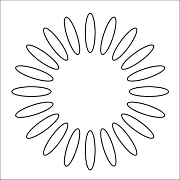
Figure 5-5 This Bezier path consists of multiple oval subpaths.
Many useful drawing operations are based on decomposing a compound path. For example, you might want to color each subpath with a different hue, as is done in Figure 5-6. Iterating through subpaths enables you to apply custom drawing operations based on the order of each path in the parent.

Figure 5-6 A unique hue fills each subpath in this shape.
Note
You iterate through the color wheel by using hue component values. Figure 5-6 created these with colorWithHue:saturation:brightness:alpha:. Its hue parameter varies from 0.0 (red) to 1.0 (red again, but after passing through all the other possible hues). Each subpath represents a 5% progression along the color wheel.
Listing 5-8’s subpaths method decomposes a path. It walks through a path’s elements, starting new subpaths whenever it encounters a move operation. Each subpath becomes a standalone UIBezierPath instance. The method stores these to a results array and returns that array to the caller.
Listing 5-8 Building a Subpath Array
// Return array of component subpaths
- (NSMutableArray *) subpaths
{
NSMutableArray *results = [NSMutableArray array];
UIBezierPath *current = nil;
NSArray *elements = self.elements;
for (BezierElement *element in elements)
{
// Close the subpath and add to the results
if (element.elementType ==
kCGPathElementCloseSubpath)
{
[current closePath];
[results addObject:current];
current = nil;
continue;
}
// Begin new paths on move-to-point
if (element.elementType ==
kCGPathElementMoveToPoint)
{
if (current)
[results addObject:current];
current = [UIBezierPath bezierPath];
[current moveToPoint:element.point];
continue;
}
if (current)
[element addToPath:current];
else
{
NSLog(@"Cannot add to nil path: %@",
element.stringValue);
continue;
}
}
if (current)
[results addObject:current];
return results;
}
Inverting Paths
Figure 5-7 shows three takes on one Bezier path. Consisting of a series of ovals rotated and placed into a circle, the leftmost image is simply filled. The middle image inverts that path, filling all areas that lie outside the path. The right image offers a third take. It inverts the path but limits that inverse to the path’s natural bounds.

Figure 5-7 Left: Original path. Middle: Inverted path. Right: Inversion within the path bounds.
Each inverse operation leverages the even/odd fill rule. That rule, as you’ll remember from Chapter 4, basically says that any point inside the path must pass through an odd number of edges on its way toward infinity. Adding one more rectangle outside the original path flips the even and odd values of every point to produce an inverted selection. The middle image (via the inverse method in Listing 5-9) adds an infinite rectangle to the path. This establishes one more boundary for all the path points, flipping their insided-ness to outsided-ness. The even/odd rule uses the new “inside”s, which now fall entirely outside the original path, to determine what to fill.
The right image does the same kind of thing—adding another rectangle so the path insides will flip to the outside—but it does this by using the original path bounds. The boundedInverse method in Listing 5-9 is responsible. Any point outside the path’s bounds remains “outside” the inverted path and won’t be filled.
Inverting paths is a powerful tool for many important drawing operations, such as inner and outer glows and inner and outer shadows. These glows and shadows, which you’ll read about later in this chapter, form the basis for many Photoshop-style primitives, which produce outstanding visuals.
Listing 5-9 Inverting Paths
- (UIBezierPath *) inverseInRect: (CGRect) rect
{
UIBezierPath *path = [UIBezierPath bezierPath];
[path appendPath:self];
[path appendPath:[UIBezierPath bezierPathWithRect:rect]];
path.usesEvenOddFillRule = YES;
return path;
}
- (UIBezierPath *) inverse
{
return [self inverseInRect:CGRectInfinite];
}
- (UIBezierPath *) boundedInverse
{
return [self inverseInRect:self.bounds];
}
Drawing Shadows
Quartz contexts support shadow drawing as an optional context-specific feature. Painted at an offset from your path that you specify, shadow drawing mimics the effect of a light source on a physical object. Figure 5-8 demonstrates what a shadow might look like when drawn into your context. Shadows can be computationally intense, but they add beautiful details to your interfaces.
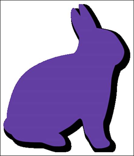
Figure 5-8 You can add shadows to a context.
Shadows, like all other context state changes, affect any subsequent drawing operations. If you want to reset state after applying a shadow, make sure to save and restore the context graphic state (GState). Setting the shadow color to clear ([UIColor clearColor].CGColor) “disables” shadow application.
Listing 5-10 wraps the CGContextSetShadowWithColor() function with an Objective-C color parameter. You specify a color, an offset (size), and a blur amount. The function updates the context state, applying those values. Here are a few points to know about shadows:
• Each shadow is added at an x- and y-offset from any drawing operations. You specify this via CGSize.
• The floating-point blur parameter indicates how hard (0) or soft (greater than 0) to make the edge.
• You can skip a color value by calling CGContextSetShadow() instead. This function defaults to a semi-translucent black color, with a 0.33 alpha value. Listing 5-10 uses this if the SetShadow() function is called with a nil color.
Listing 5-10 Specifying a Context Shadow
void SetShadow(UIColor *color,
CGSize size, CGFloat blur)
{
CGContextRef context =
UIGraphicsGetCurrentContext();
if (context == NULL)
{
NSLog(@"Error: No context to draw into");
return;
}
if (color)
CGContextSetShadowWithColor(context,
size, blur, color.CGColor);
else
CGContextSetShadow(context, size, blur);
}
Table 5-1 demonstrates the effects that shadow parameters have on drawing.
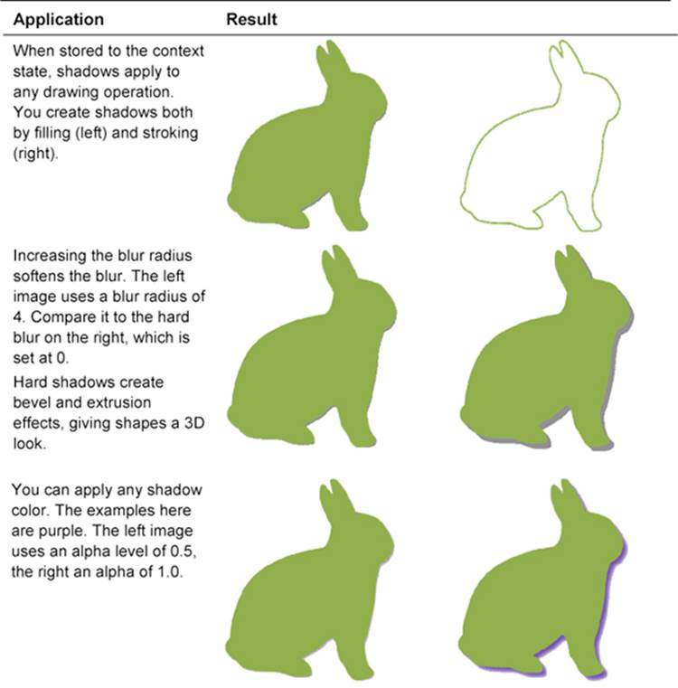
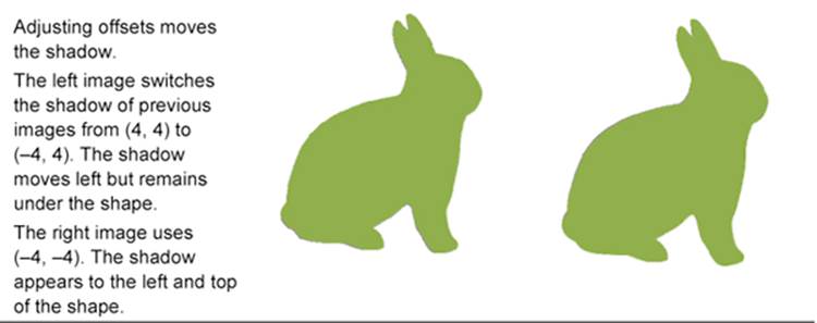
Table 5-1 Setting Shadows
The Cost of Shadows
There’s no getting around the fact that shadows place a high computational load on your drawing. Although visually gorgeous, they’re not necessarily a feature you want to use for real-time high-performance interface elements.
Whenever possible, profile your drawing operations during development to get a sense of their cost. Here’s a quick-and-dirty approach to use as you build your methods, to track elapsed time:
NSDate *start = [NSDate date];
// Perform drawing operations
NSLog(@"%f seconds", [[NSDate date] timeIntervalSinceDate:start]);
Drawing an Inner Shadow
Figure 5-9 shows an image created by filling a Bezier path with an added inner shadow. An inner shadow, as the name suggests, adds a shadow drawn within the bounds of the path. Depending on how your brain is processing it at the moment, the shadow either looks as if the edges outside the shape are casting a shadow or, if you can make your mind do a flipflop, the shape expresses an embossed edge.
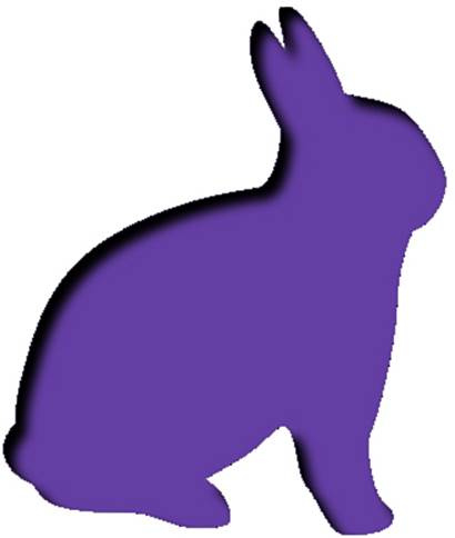
Figure 5-9 You can create a path with an inner shadow.
Figure 5-10 shows the drawing operations you combine to create the inner shadow. The first operation is a matte fill operation. The second operation builds the shadow, which is masked inside the shape.
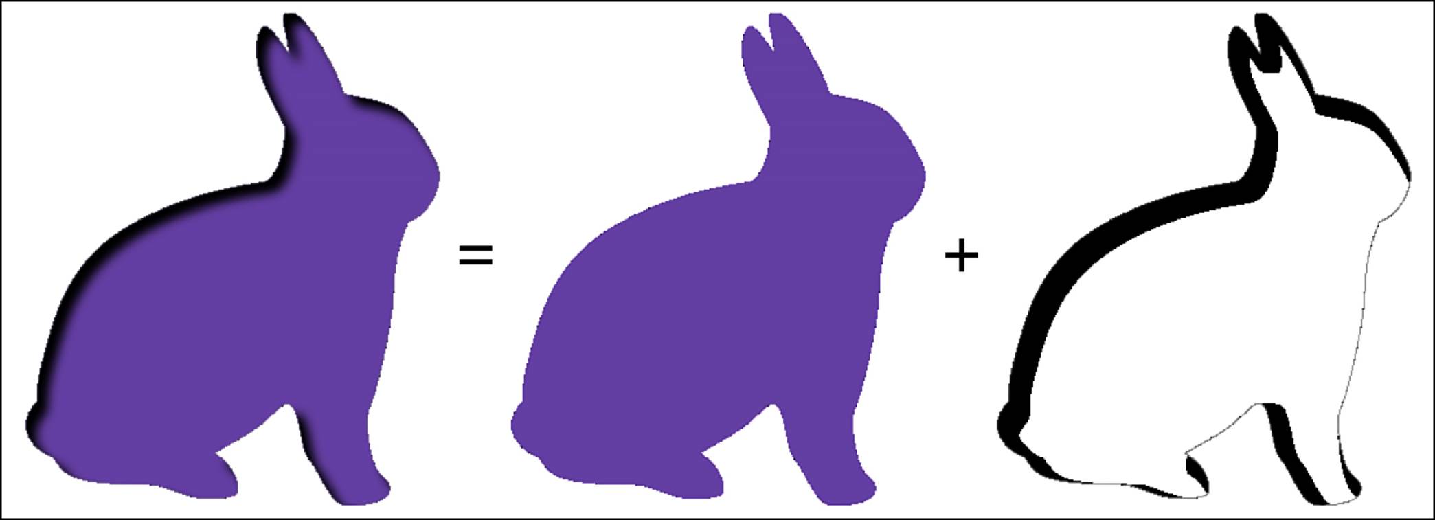
Figure 5-10 Left: Original path. Middle: Inverted path. Right: Inversion within the path bounds.
Building the shadow requires you to invert the path, as you did in Listing 5-9. You allow the context to draw a shadow for that inverted shape, which naturally falls within the remaining portion of the original path. Clipping the context ensures that nothing is drawn outside that path.
Listing 5-11 shows the steps that draw the inner shadow. First you set the context shadow state. This function applies this within a GState stack, ensuring that the state restores after the drawing operation. It also clips the drawing area to the path passed as the parameter. This ensures that all drawing takes place within path bounds.
Next, it sets the drawing color. Since all drawing is done outside the clipping region, theoretically any non-clear color would work. In practice, however, you’ll encounter slight clipping errors where the path border experiences high curvature. This is a known issue. Using the shadow color avoids visual discontinuities.
Finally, this function fills the inverse of the path with that color. Due to the clip, the only drawing that’s created is the shadow, which is shown on the right in Figure 5-10.
Listing 5-11 Drawing an Inner Shadow
void DrawInnerShadow(UIBezierPath *path,
UIColor *color, CGSize size, CGFloat blur)
{
CGContextRef context = UIGraphicsGetCurrentContext();
if (context == NULL)
{
NSLog(@"Error: No context to draw to");
return;
}
// Build shadow
CGContextSaveGState(context);
SetShadow(color,
CGSizeMake(size.width, size.height), blur);
// Clip to the original path
[path addClip];
// Fill the inverted path
[path.inverse fill:color];
CGContextRestoreGState(context);
}
Listing 5-12 offers another take on the inner shadow. I call this approach the “PaintCode” solution because it was originally inspired by code exported by PixelCut (http://pixelcut.com) from their PaintCode application. It’s fussier than the solution from Listing 5-11, but it avoids the edge case that blends tiny bits of the inverted path’s fill color with your drawing at highly inflected curves. It works by tweaking the inverted path ever so slightly, to clip a tiny bit away from that edge. This results in a cleaner shadow presentation.
Listing 5-12 Drawing a (Better) Inner Shadow
- (void) drawInnerShadow: (UIColor *) color
size: (CGSize) size blur: (CGFloat) radius
{
if (!color)
COMPLAIN_AND_BAIL(@"Color cannot be nil", nil);
CGContextRef context = UIGraphicsGetCurrentContext();
if (context == NULL)
COMPLAIN_AND_BAIL(@"No context to draw into", nil);
CGContextSaveGState(context);
// Originally inspired by the PaintCode guys
// http://paintcodeapp.com
// Establish initial offsets
CGFloat xOffset = size.width;
CGFloat yOffset = size.height;
// Adjust the border
CGRect borderRect =
CGRectInset(self.bounds, -radius, -radius);
borderRect =
CGRectOffset(borderRect, -xOffset, -yOffset);
CGRect unionRect =
CGRectUnion(borderRect, self.bounds);
borderRect = CGRectInset(unionRect, -1.0, -1.0);
// Tweak the size a tiny bit
xOffset += round(borderRect.size.width);
CGSize tweakSize = CGSizeMake(
xOffset + copysign(0.1, xOffset),
yOffset + copysign(0.1, yOffset));
// Set the shadow and clip
CGContextSetShadowWithColor(context, tweakSize,
radius, color.CGColor);
[self addClip];
// Apply transform
CGAffineTransform transform =
CGAffineTransformMakeTranslation(
-round(borderRect.size.width), 0);
UIBezierPath *negativePath =
[self inverseInRect:borderRect];
[negativePath applyTransform:transform];
// Any color would do, use red for testing
[negativePath fill:color];
CGContextRestoreGState(context);
}
Embossing a Shape
Applying both a dark inner shadow to the bottom left and a light inner shadow to the top right creates the embossed effect you see in Figure 5-11. This effect uses a soft blur, to create smooth transitions:
DrawInnerShadow(path, [[UIColor whiteColor]
colorWithAlphaComponent:0.3f],
CGSizeMake(-4, 4), 4);
DrawInnerShadow(path, [[UIColor blackColor]
colorWithAlphaComponent:0.3f],
CGSizeMake(4, -4), 4);
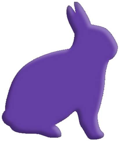
Figure 5-11 You can combine light and dark inner shadows to “emboss” a Bezier path.
You can combine a softer inner shadow with a sharp outer shadow to create a bevel effect for your shape, like the one in Figure 5-12:
DrawInnerShadow(bunny, WHITE_LEVEL(0, 0.5),
CGSizeMake(-4, 4), 2);
DrawShadow(bunny, WHITE_LEVEL(0, 0.5),
CGSizeMake(2, -2), 0);
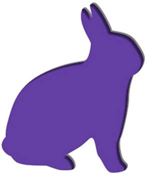
Figure 5-12 You can “bevel” a path by combining an inner shadow and outer shadow with sharp edges.
Drawing Inner and Outer Glows
Unlike shadows, glows have no direction. They surround a path on all sides, as in Figure 5-13, where a soft green outer glow highlights the edges of the purple bunny.
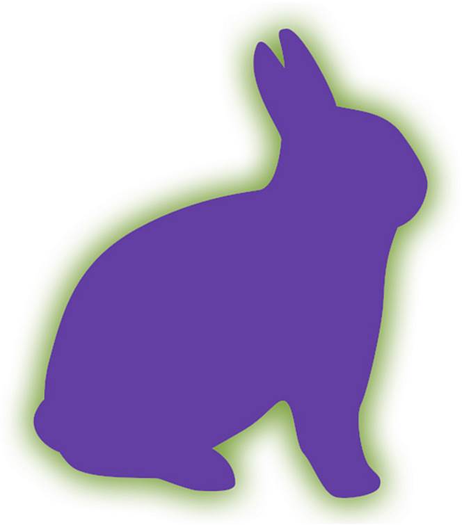
Figure 5-13 A green outer glow is applied outside the path.
With all shadows, there are several ways you can achieve a glow effect; the simplest involves using Quartz shadows, as in Listing 5-13. You draw a shadow directly over the path with an offset of (0, 0). The blur parameter spreads the shadow for you, equally on all sides.
You can use path clipping to draw the shadow outside or inside a path. When clipped inside, the glow is called inner. A simple black inner glow creates the 3D feel you see in Figure 5-14.
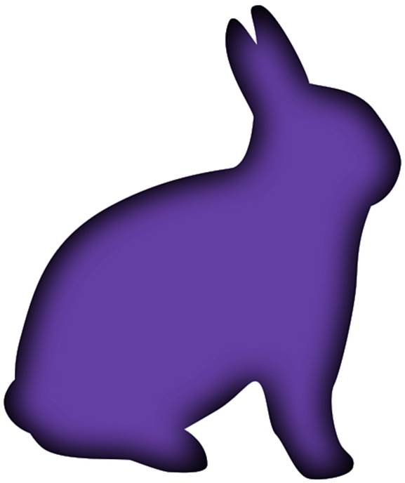
Figure 5-14 Applying an inner glow.
Listing 5-13’s results tend to be fairly light in coverage, even when used with fully opaque colors. For this reason, you may want to apply the effect more than once, like this:
[path fill:purpleColor];
[path drawInnerGlow:BLACKCOLOR withRadius:20];
[path drawInnerGlow:BLACKCOLOR withRadius:20];
Listing 5-13 Drawing Inner and Outer Glows
- (void) drawOuterGlow: (UIColor *) fillColor
withRadius: (CGFloat) radius
{
CGContextRef context = UIGraphicsGetCurrentContext();
if (context == NULL)
{
NSLog(@"Error: No context to draw to");
return;
}
CGContextSaveGState(context);
[self.inverse clipToPath];
CGContextSetShadowWithColor(context,
CGSizeZero, radius, fillColor.CGColor);
[self fill:[UIColor grayColor]];
CGContextRestoreGState(context);
}
- (void) drawInnerGlow: (UIColor *) fillColor
withRadius: (CGFloat) radius
{
CGContextRef context = UIGraphicsGetCurrentContext();
if (context == NULL)
{
NSLog(@"Error: No context to draw to");
return;
}
CGContextSaveGState(context);
[self clipToPath];
CGContextSetShadowWithColor(context,
CGSizeZero, radius, fillColor.CGColor);
[self.inverse fill:[UIColor grayColor]];
CGContextRestoreGState(context);
}
Combining Glows
Inner and outer glows lend impact to your path drawings, especially when combined, as in Figure 5-15. Together, they form a basis for many successful interface element designs by providing dimensional depth. As you’ll discover in Chapter 6, adding gradient overlays and underlying textures adds even further realism.
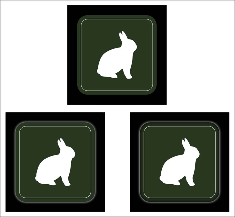
Figure 5-15 Original (top). Added outer glow (bottom left). Added inner and outer glow (bottom right).
Reversing a Path
Unfortunately, reversing a Bezier path—especially a complex one—using bezierPathByReversingPath is broken in the iOS 6.x and early release iOS 7 SDKs. A solution depends on decomposing each path into first, its subpaths (see Listing 5-8; each subpath begins with a move operation, and may or may not end with a close operation), and then into the component elements (see Listing 5-2).
In general, you want to reverse a path when you’re applying animation or a drawing effect to the path representation instead of just filling or stroking it. For example, if you’re using a Bezier path to lay out text along the path, reversing the order enables you to change the way drawing proceeds.
Reversing paths turns out to be a bit trickier than you might think. That’s because when you reverse items, you have to take close points into account. That means a reversed path often looks like this:
• Move to the destination point of the second-to-last element (the one that comes before the close command).
• Add a line to the first element of the path.
• Reverse each line and curve, using the destination for each item as the start point and the start element as the destination.
• If you had a close command in the original path, apply that close to avoid odd line cap artifacts.
Listing 5-14 shows the lengthy solution. It consists of two methods. The public reversed method decomposes the path into subpaths, reversing the order of those subpaths. It then calls the private reverseSubpath: method, which flips each individual subpath.
Listing 5-14 Creating a Reversed Bezier Path
- (UIBezierPath *) reverseSubpath:
(UIBezierPath *) subpath
{
NSArray *elements = subpath.elements;
NSArray *reversedElements =
[[elements reverseObjectEnumerator] allObjects];
UIBezierPath *newPath = [UIBezierPath bezierPath];
BOOL closesSubpath = NO;
// Locate the element with the first point
BezierElement *firstElement;
for (BezierElement *e in elements)
{
if (!POINT_IS_NULL(e.point))
{
firstElement = e;
break;
}
}
// Locate the element with the last point
BezierElement *lastElement;
for (BezierElement *e in reversedElements)
{
if (!POINT_IS_NULL(e.point))
{
lastElement = e;
break;
}
}
// Check for path closure
BezierElement *element = [elements lastObject];
if (element.elementType == kCGPathElementCloseSubpath)
{
if (firstElement)
[newPath moveToPoint:firstElement.point];
if (lastElement)
[newPath addLineToPoint:lastElement.point];
closesSubpath = YES;
}
else
{
[newPath moveToPoint:lastElement.point];
}
// Iterate backwards and reconstruct the path
CFIndex i = 0;
for (BezierElement *element in reversedElements)
{
i++;
BezierElement *nextElement = nil;
BezierElement *workElement = [element copy];
if (element.elementType == kCGPathElementCloseSubpath)
continue;
if (element == firstElement)
{
if (closesSubpath) [newPath closePath];
continue;
}
if (i < reversedElements.count)
{
nextElement = reversedElements[i];
if (!POINT_IS_NULL(workElement.controlPoint2))
{
CGPoint tmp = workElement.controlPoint1;
workElement.controlPoint1 =
workElement.controlPoint2;
workElement.controlPoint2 = tmp;
}
workElement.point = nextElement.point;
}
if (element.elementType == kCGPathElementMoveToPoint)
workElement.elementType =
kCGPathElementAddLineToPoint;
[workElement addToPath:newPath];
}
return newPath;
}
// Reverse the entire path
- (UIBezierPath *) reversed
{
// [self bezierPathByReversingPath] does not work
// the way you expect. Radars are filed.
UIBezierPath *reversed = [UIBezierPath bezierPath];
NSArray *reversedSubpaths =
[[self.subpaths reverseObjectEnumerator] allObjects];
for (UIBezierPath *subpath in reversedSubpaths)
{
UIBezierPath *p = [self reverseSubpath:subpath];
if (p)
[reversed appendPath:p];
}
return reversed;
}
Visualizing Path Order
Listing 5-15 enables you to trace a path, displaying the progress of the path from beginning (dark) to end (light). Although I developed this routine specifically for debugging, I’ve found it handy to use in a variety of circumstances.
For example, the max percentage parameter helps power custom animations. If you eliminate the color phases, the function works as a progress pattern, filling to a point you specify. If you draw lines instead of dots between iterative points, you can also build an angular version of the entire path with phased color. Playing with a color’s white levels (as in Figure 5-16) or hues (as in Figure 5-5) provides a natural progression: from black to white or around the color wheel.
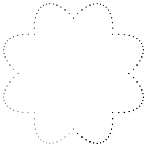
Figure 5-16 You can view the progress of a path from start to end.
Listing 5-15 Tracing a Path Progression
void ShowPathProgression(
UIBezierPath *path, CGFloat maxPercent)
{
CGContextRef context = UIGraphicsGetCurrentContext();
if (context == NULL)
{
NSLog(@"Error: No context to draw to");
return;
}
// Bound the percent value
CGFloat maximumPercent =
fmaxf(fminf(maxPercent, 1.0f), 0.0f);
CGContextSaveGState(context);
// One sample every six points
CGFloat distance = path.pathLength;
int samples = distance / 6;
// Change in white level for each sample
float dLevel = 0.75 / (CGFloat) samples;
UIBezierPath *marker;
for (int i = 0; i <= samples * maximumPercent; i++)
{
// Calculate progress and color
CGFloat percent = (CGFloat) i / (CGFloat) samples;
CGPoint point = [path pointAtPercent:percent
withSlope:NULL];
UIColor *color =
[UIColor colorWithWhite:i * dLevel alpha:1];
// Draw marker
CGRect r = RectAroundCenter(point, CGSizeMake(2, 2));
marker = [UIBezierPath bezierPathWithOvalInRect:r];
[marker fill:color];
}
CGContextRestoreGState(context);
}
Summary
This chapter introduces Bezier paths in depth. You saw how to decompose, reconstruct, and paint paths to create a variety of drawing effects. Here are a few final thoughts for this chapter:
• When testing drawing in the simulator, you can actually write from the simulated iOS app to your normal OS X file system. For example, you might want to save a copy of the image you just created in your context by adding a line like this:
[UIImagePNGRepresentation(image)
writeToFile: @"/Users/ericasadun/Desktop/figure.png"
atomically: YES].
• Pay attention to the changes you make in a context. Drawing with shadows will change the context state. Embed those updates in GState save and restore calls so you won’t inadvertently affect other parts of your drawing.
• Be really careful when trying to replicate Photoshop-style effects in your app. Use Instruments to profile your drawing and check for expensive, repeated operations. It’s often a lot faster to import images created in other applications and render them into your contexts than to calculate effects directly. Instead of calculating shines and shadows, you can composite them.
• Calculating progress along a path provides a wealth of implementation opportunities. You can draw a path over time, lay out type on that path, animate an object along the path, and more. This chapter shows you a few possibilities, but there’s far more you can discover on your own.
• When applying advanced drawing techniques, you might want to increase the size of the drawing space to limit edge effects. This trades off calculation space and speed against better-quality output, which can be scaled back in image views.