Making Simple Robots (2014)
Chapter 1. Robots Made from Interesting Materials
We have been working on the geometry, algorithms, and manufacture of novel ways to make materials that are re-programmable, repurposable, and blend the boundaries between materials science, computer science, biology, and mathematics.
— OtherLab
When you think of robots, what do you picture them being made out of? In classic science fiction books and movies, it’s almost always sheet metal. Household robots and robotic toys are usually made of hard plastic. But in robotics labs around the world, scientists are looking at every material imaginable. Today state-of-the-art materials and manufacturing processes are opening up new possibilities in robot construction. Instead of using heavy, rigid bodies, researchers are trying out thin, flexible skins that let robots bend, squeeze, and stretch. One goal is the creation of robots that mimic their biological counterparts. These biomimetic robots move more like living things, and often need less programming and less power to get them going. They are also usually more “compliant”—a robotics term that means they yield when they run into people and things in their path, instead of mowing them down.
Even more exciting is the idea of a “smart body” that uses the overall design or molecular structure of a robot to control how it behaves. One way is by using programmable material such as shape memory polymers and alloys. These are materials that can be trained to change their physical size or shape when exposed to an outside stimulus like light or heat. For instance, a straight piece of shape memory alloy (SMA) wire can be preset to coil up like a spring when placed in a cup of hot water.
Some researchers are working on smart bodies made of a common childhood art material—shrinkable plastic (similar to those sold in crafts stores under the name Shrinky Dinks). When heated, the plastic sheets contract to about 60 percent of their original height and width. Kids draw on them and crafters run them through computer printers to make colorful pendants. But at North Carolina State University (Figure 1-1), researchers printed thick black lines on the sheets and exposed them briefly to infrared light, the kind used in heat lamps. Since dark colors absorb more light energy than light colors, the black lines heated up while the clear parts stayed cool, causing the sheets to bend. The results were self-folding sheets of plastic that could transform themselves into boxes or other 3D shapes automatically.
|
|
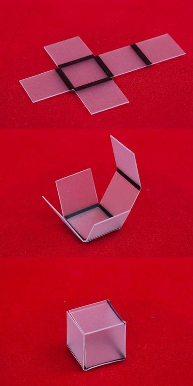
Figure 1-1. Self-folding sheets of shrinkable plastic that are activated using heat. Credit: Ying Liu and Jacob Thelen, North Carolina State University.
However, Shrinky Dinks can’t go back and forth between their shrunken and stretched-out states. Other shape memory materials can. Researchers are using this flexibility to create artificial muscles, which fall into the category of actuators, things that make a robot move. In 2009, Ray Baughman at the University of Texas at Dallas showed off artificial muscles made of a type of shape memory polymer called carbon nanotube. The atoms in a carbon nanotube are arranged in a honeycomb, like the surface of a geodesic dome. This makes the material as stiff as steel in one direction, but stretchy in the other. It can also operate at extreme temperatures, which makes it ideal for space missions. Baughman’s team originally used the material in the form of an aerogel, sometimes described as“frozen smoke.” Aerogel is a solid so light that it has virtually the same density as air. A voltage applied to a strip of carbon nanotube aerogel made it expand 10 times farther and 1,000 times faster than a natural muscle. More recently, Baughman created wax-filled strands of carbon nanotube yarn that expanded when the wax was melted at high temperatures. Someday the yarn may be woven into smart materials that change shape when armed or cooled.
SMA wire made out of nitinol—a blend of the metals nickel and titanium—is being used as an actuator on very small and very flexible robot bodies. In 2012, the Octopus Project released video of an underwater robot using its SMA-actuated tentacles to crawl across a wading pool. And at Virginia Tech, researchers are working on Robojelly, a jellyfish-shaped robot that moves with the help of strips of SMA composite. The Robojelly helps engineers and biologists study how jellyfish swim without having to worry about keeping a real animal alive and healthy. The hope is to create a design that can someday be applied to underwater vehicles.
Along with new materials, many forward-thinking inventors are also turning to the past for inspiration. Among the avenues they are exploring are low-tech materials like paper and rubber. Their light weight and springiness can make them easier to power. And because they’re so commonly available, they’re easier and cheaper to design, build, upgrade, and replace. In fact, some researchers believe they can be manufactured in such large quantities as to become disposable—send them out to explore or do a job and don’t worry about whether they can make it back.
The projects in this chapter will let you get your feet wet making simple robots by playing around with some of the interesting materials being used in cutting-edge robotics research today: shape memory alloy wire, paper, and rubber. The projects themselves are extremely basic—more like proof-of-concept designs that test the capabilities of the materials than something resembling an actual robot. But the Adaptations and Extensions section of the project descriptions point you towards further areas of exploration if you want to keep going. Be sure to check the Linkboxes for additional background information and tutorials online.
Project: Make Actuated Paper
Actuated paper is a type of programmable material that can move on its own with the help of embedded shape memory material.
What It Does
Actuated paper can fold and refold itself into various shapes as needed. Researchers are studying ways to use it for all-purpose robots that can alter their shape as needed. Transformable robots would be very handy on space missions and other places where getting new supplies could be difficult. Artists and designers are also using actuated paper to make kinetic sculptures and furnishings. By adding sensors and other electronics, it’s possible to create actuated paper structures that respond to the environment around them.
Where It Came From
Paper was invented by the Chinese around 105 AD, and it opened up a whole new world of possibilities in what we now call product design. As a surface for print, it replaced parchment and papyrus for books and metal for money. And because it was thin enough to fold, stiff enough to hold its shape, and light enough to be portable, it was also useful for boxes, containers, toys, and decorations. By the 1700s, mechanized papermaking brought the price down enough for ordinary people to afford, and folding and cutting paper into designs became a popular hobby in Europe and Asia.
The use of paper as a material for robot bodies takes its inspiration from two popular artforms: pop-up illustrations and origami. Pop-up illustrations, used in children’s books and greeting cards, are folded structures that lie flat when the pages are closed, and spring upright when the pages are open. Origami, the traditional Japanese art of paper folding, is both a favorite children’s pastime and a high art. Extremely complex and beautiful designs can be created by using techniques like modular designs (building a larger piece out of smaller separate pieces of origami) and technical folding (pre-creasing the paper in regular geometric patterns). Action origami pieces, which move when you pull or push certain spots, range from the traditional hopping frog to amazing spinning spirals and tumbling boxes. Origami designers share their original creations using written directions, diagrams, or crease patterns that indicate where the paper was folded on a flattened piece of paper.
In recent years origami engineering has become a field of scientific study. In 2009, MIT mathematician Erik Demaine and a team at MIT proved that a type of origami fold called the box pleat pattern could be used to create basically any shape possible. Next, Demaine, MIT roboticist Daniela Rus, and Harvard’s Robert Wood created a box pleat–creased sheet actuated with SMA and magnets that could fold itself into a boat and a paper airplane. Then in 2014, the same team published an article describing a heat-activated origami robot made from a flat sheet made of layers of copper, paper, and shape memory polymer.
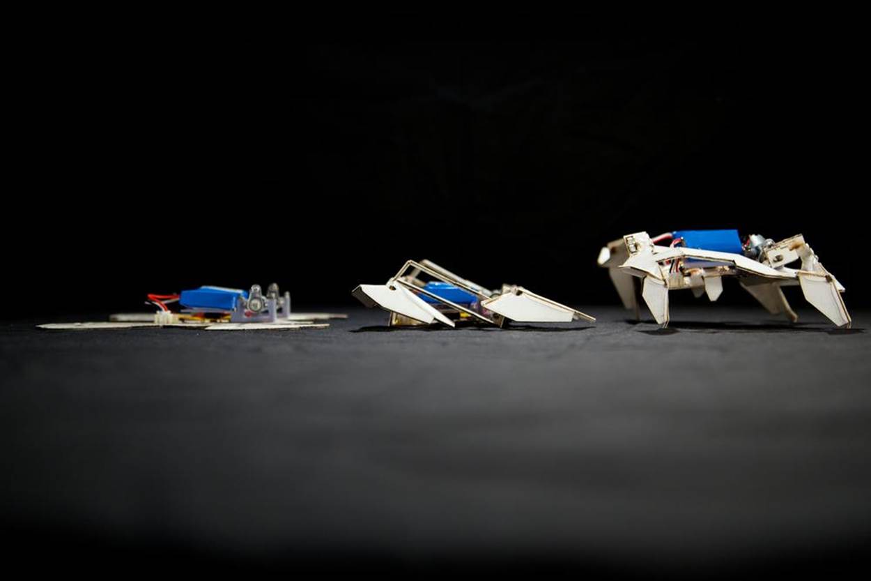
Figure 1-2. This robot made of paper and heat-activated shape memory polymer from Harvard and MIT scientists can fold itself up and scurry away. Credit: Seth Kroll/Harvard’s Wyss Institute.
The copper inner layer was etched with traces that could carry electrical current. When a battery was connected, an attached microprocessor would send current through the copper, heating up the polymer, which would begin to fold up in sequence. Such a robot could be programmed to take on different shapes. One demonstration model that folded itself into the shape of a bug could immediately scurry away on four motorized legs.
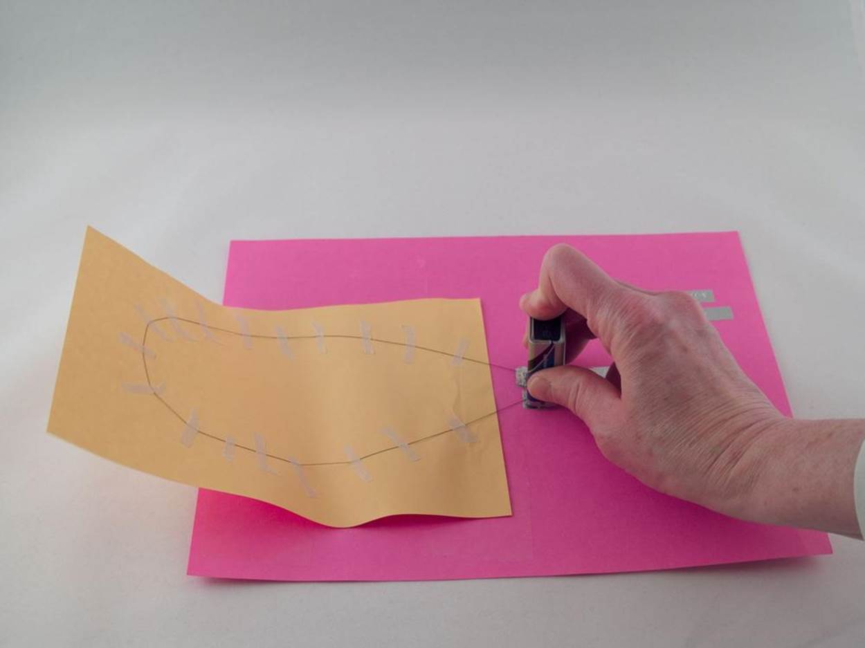
Other researchers like Jie Qi of the MIT Media Lab are bridging the gap between origami engineering and art by making cranes that flap their wings and paper “vines” that retract when touched (see Figure 1-3) .
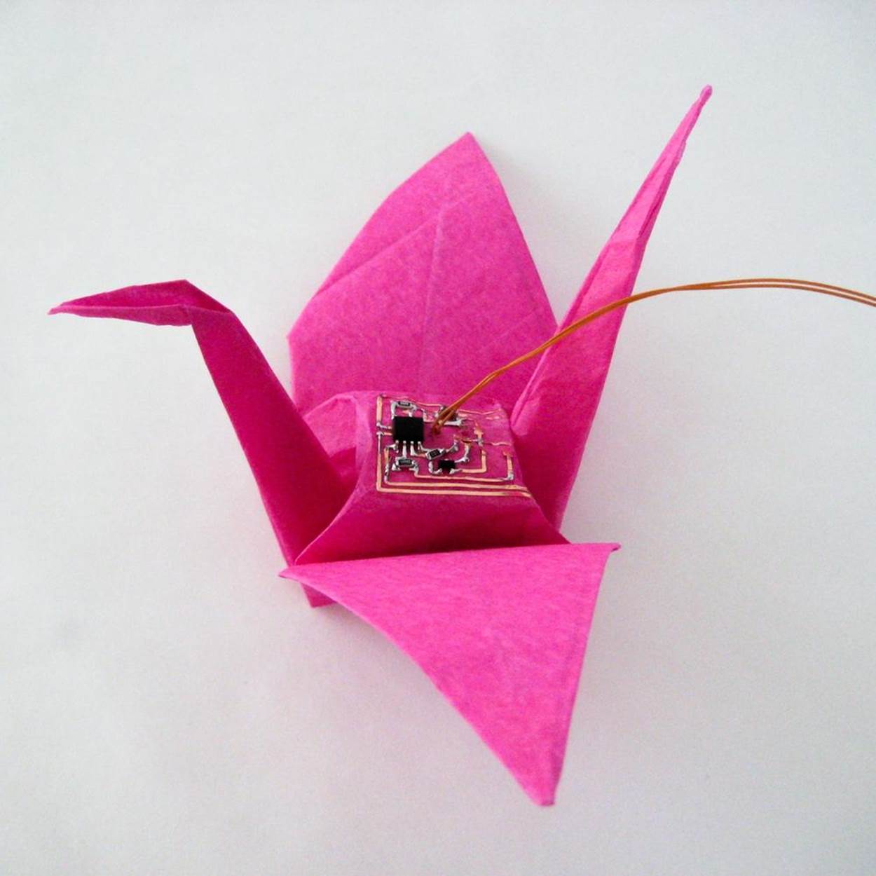
Figure 1-3. Jie Qi’s moving paper sculptures are activated by shape memory alloy wire. Credit: Jie Qi.
Paper folding and pop-ups are also being used to create biomimetic robots. Researchers at the UC Berkeley Biomimetic Millisystems Lab build tiny robots from folded cardboard using a process they call Smart Composite Microstructures. A flexible layer of plastic is sandwiched between two layers of cardboard. When the robot model is folded into shape along thin precut slits, the plastic inner layer become a flexible hinge that is nearly frictionless. Assembling a working robot using this process takes less than an hour, and the use of inexpensive materials makes it possible for researchers to continually refine the design and create new prototypes to test out.
One of the first minirobots built using this approach was an open source matchbox-sized insectoid called RoACH (Robotic Autonomous Crawling Hexapod). RoACH is actuated by shape memory alloy wires that pull a sliding plate attached to its six legs. RoACH has two degrees of freedom, or directions in which a part of its body can move. Its sliding plate can move up and down to lift and lower the legs, and back and forth to make the legs sweep backward or forward. That’s all it needs to make its legs propel it forward or backward. A later design, DASH (Dynamic Autonomous Sprawled Hexapod), uses a motor to drive the six legs. DASH can run along at 15 times its body length per second and bounce back from falls the height of a multistory building. It has even been adapted into a Dash Robotics DIY kit for students and hobbyists that can be controlled by a smartphone or tablet (Figure 1-4).
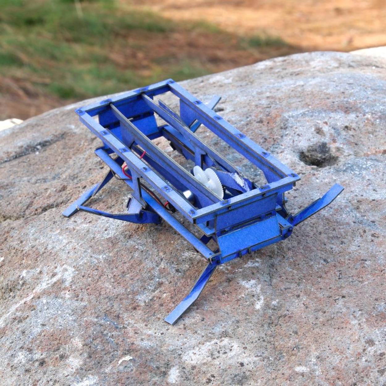
Figure 1-4. Dash is a robotic bug made from laser-cut cardboard and easily assembled. Credit: Dash Robotics.
How It Works
As a material for building robots, paper is both stiff enough to stand up and support a small load, yet soft enough to act like a spring when folded. Paper robots like DASH and RoACH use a kind of pop-up hinge called a Sarrus linkage, which opens into a hollow parallelogram shape that can swing back and forth to create a walking motion. Action origami models like the hopping frog rely on the potential energy created when paper is folded and held down under pressure.
Nitinol was discovered in 1959 by Navy researcher William J. Buehler. (Its name stands for Nickel Titanium Naval Ordnance Laboratory.) Extremely flexible and strong, it has been used in orthopedic and cardiovascular surgery, solid-state heat engines, pipe couplers for aircraft, eyeglass frames, and toys. Its shape memory comes from the fact that the atoms in each nitinol molecule rearrange themselves into different crystalline shapes at different temperatures. At high temperatures, the atoms go into what is called anaustenite phase, in which each nickel atom is surrounded by eight titanium atoms arranged in a cube. At lower temperatures, they revert to a martensite phase, a more complex arrangement of atoms. There are various kinds of nitinol, which can be programmed to phase shift at different temperatures for different uses. Some nitinol products can be programmed by the user. Other kinds come preset.
Robot builders often use Flexinol, a brand of nitinol wire made by Dynalloy. It’s preset to shrink between 5 and 10 percent when heated by an electrical current. When cool, it can be stretched back out to its original resting size. Because the change in size is so small, and because it needs some kind of force to help it stretch back out to its original size, the effect of a Flexinol actuator depends on the design of the robot and what it is made of. If it is anchored to a stiff material like metal or wood, a spring or rubber band can be used to pull it back to its resting length. In a paper model, gravity or the springiness of the paper itself can serve the same purpose. However, in simple paper models, the movement created by a Flexinol actuator is usually very subtle. It’s great for making paper sculptures wave gently in a lifelike motion. Really dramatic effects, such as robobugs that run or fly, require more advanced paper engineering.
Making the Project
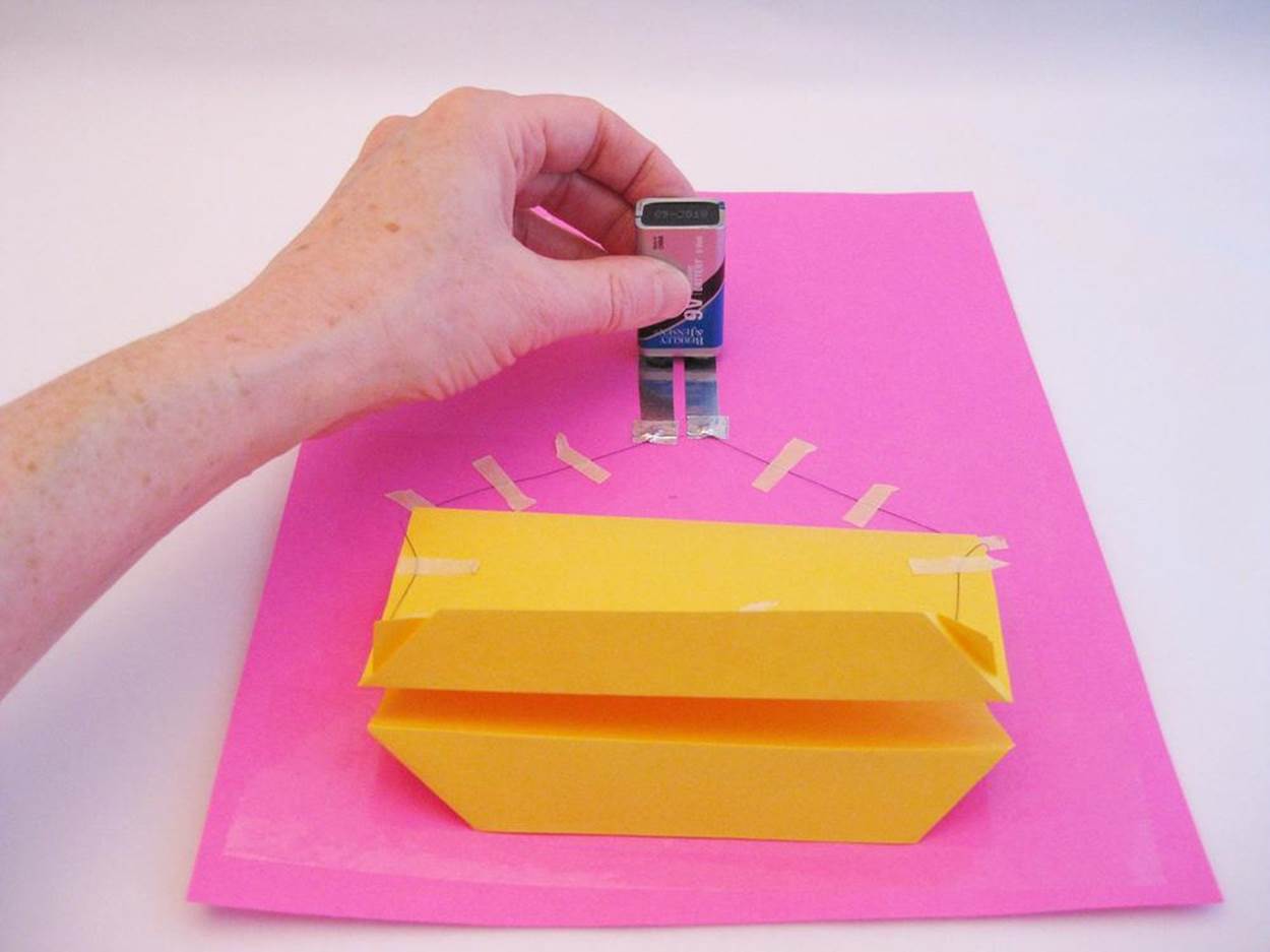
When it comes to building robots, you can’t get simpler than folded paper. For this project, you won’t be building a robot that walks and talks—but you will get to practice the kind of rapid prototyping techniques used in real robotics labs by designing a smart body using common household materials. You’ll also get to practice making an electrical circuit, and discover how to use the futuristic programmable material Flexinol to make actuated paper that jumps, sways, and waves.
While you can find almost all the supplies for this project around your house or at your local crafts or hardware store, you will most likely have to order your nitinol wire online. Be sure to get extra, since without a controller or protective components there’s a slight chance of frying your Flexinol. More importantly, you’ll want enough to play around with as you come up with your own ideas for building actuated models from paper and other materials.
NOTE
Don’t forget to document your work!
Project Parameters
§ Time Needed: 2–3 hours
§ Cost: $15–$40
§ Difficulty: Easy to moderate
§ Safety Issues: Some 9V batteries come “overcharged” from the factory and may deliver too much voltage at first. Be careful to use batteries in very short bursts so as not to overheat the SMA wire or create sparks around the paper model.
What You Need to Know
§ Skills You Already Have: Craft skills (sewing, beading) helpful but not required
§ Skills You Will Learn: Building an electrical circuit
Gather Your Materials
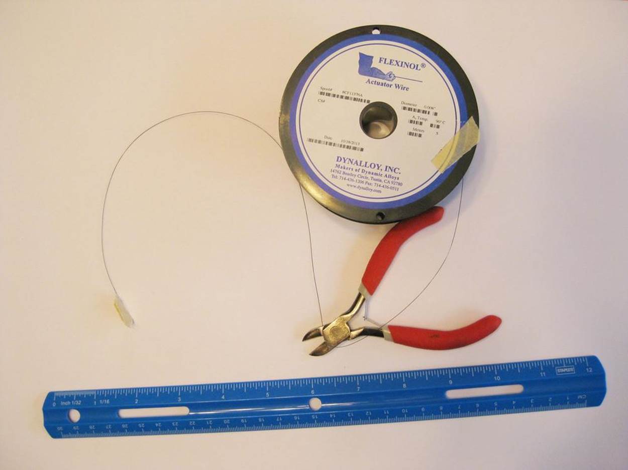
§ Flexinol wire, at least 2 feet long (note: I used .008-inch high temperature (HT) wire for this project. You may want to start with .006-inch diameter, which according to the manufacturer can be activated continuously without burning out. A 5-meter (15-foot) roll is less than $25 from RobotShop).
§ Masking tape
§ Wire cutters
§ Needle-nose pliers
§ Two or more small metallic jewelry crimp beads (available in packs of 50 at craft stores)
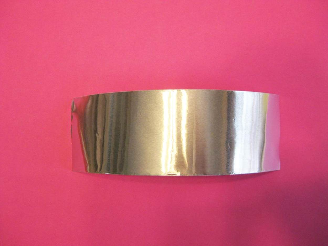
§ Peel-and-stick aluminum foil tape (look for a duct-tape-sized roll of actual foil, available in the heating department of hardware stores, not metallic colored duct tape)
§ Pen
§ Scissors
§ Paper—letter-sized copy paper and/or cardstock
§ Clear, wide packing tape
§ 9V battery (nonrechargeable)
Directions
Step 1: List Your Requirements
The goal of this project is to explore different ways to use the springiness of folded paper in robot bodies and other moving models, and how to magnify the movement provided by the Flexinol wire actuator.
Step 2: Plan Your Project
There are several different paper building techniques you can try with the Flexinol wire. The simplest and most dramatic movements are making a strip of paper curl up, or creating a hinge to open and shut a flap of paper. To avoid wasting SMA wire, you can build a test platform that lets you try out multiple paper designs using the same piece of wire.
Step 3: Stop, Review, and Get Feedback
Before you begin, you might want to research more about origami techniques. Practice interesting models and learn about the traditional and technique bases used to create new designs by checking out the websites in the Linkbox below, including YouTube how-to videos by instructors like Jeremy Shafer, or any of the books by Robert J. Lang.
For more background about nitinol and how it works, the Dynalloy and Robotshop websites, also linked below, contain useful information. The Make: website also has a detailed article by MIT Media Labs’ Jie Qi, and you’ll find inspiring actuated paper art on her website.
WARNING
Only activate the wire for a few seconds at a time—just until the wire stops contracting. Overheating the wire can “deprogram” it—or worse, set the paper on fire.
Step 4: Build Your Prototype
Follow these steps to build a test platform for your SMA wire:
1. Use the wire cutters to clip a piece of .008-inch diameter Flexinol wire that is 18 inches long. (If you are using .006-inch wire, you can use a piece as short as 9 inches.) For ease of handling—and to avoid losing track of the hair-thin, bouncy wire until you attach it to something—wrap a bit of masking tape around it like a tag.
2. The wire will be easier to work with and make a better electrical connection if you crimp the ends. (Crimping is also necessary if you want to solder SMA wire, since solder will work its way off of the wire itself as it expands and contracts.) Take the pliers and bend about 1/4 inch (6 mm) of one end of the wire into a tight U shape. Slip a crimp bead onto the wire and around the bend. Then push the bead back, this time catching the loose end in the bead as well.
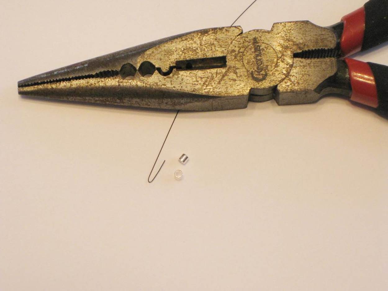
3. Crunch down on the bead with the pliers, squeezing as hard as you can until the bead is flat. Check whether the bead can still slide up and down—if it can, angle the pliers a bit and squeeze again. Crimp the other end the same way.
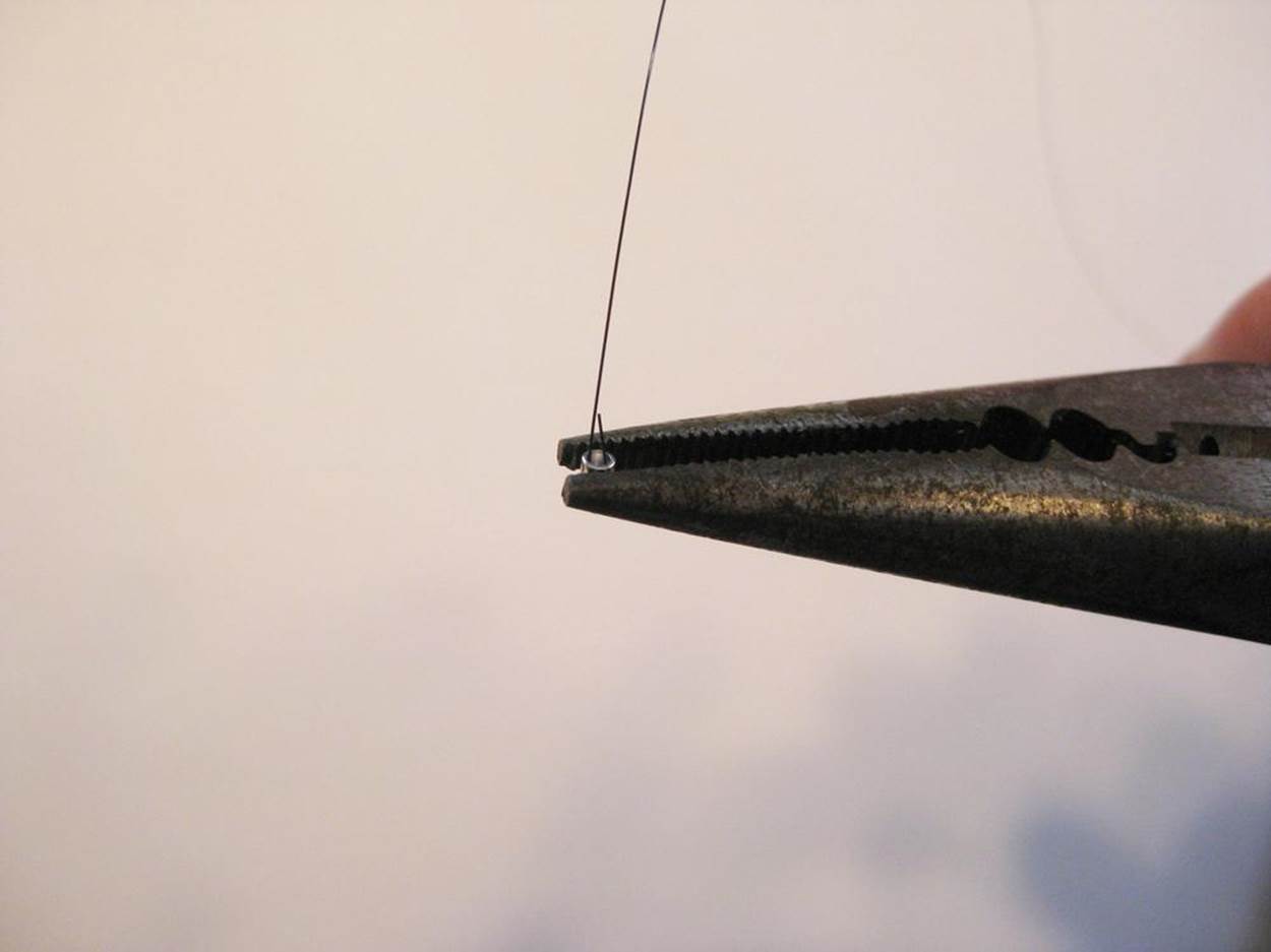
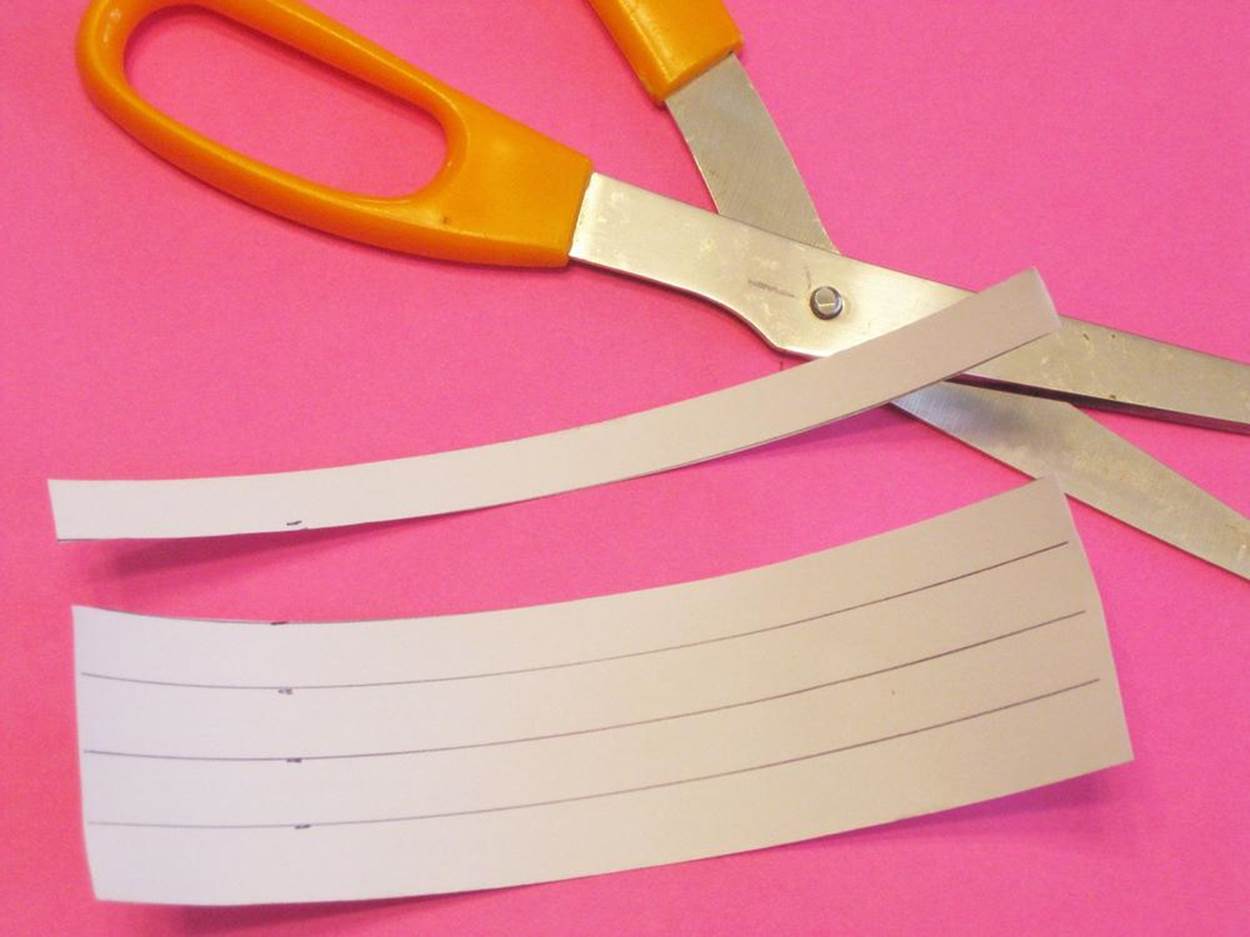
4. Next, you will use narrow strips of peel-and-stick adhesive aluminum foil tape as hand-made circuit wiring, known as traces. (Thanks to Make: magazine writer Chris Connors for this trick!) Cut a piece of foil tape about 6 inches long.
Flip it over to the paper side, and use a pen to mark off five long strips each 3/8 inch (1 cm) wide. Cut along the lines.
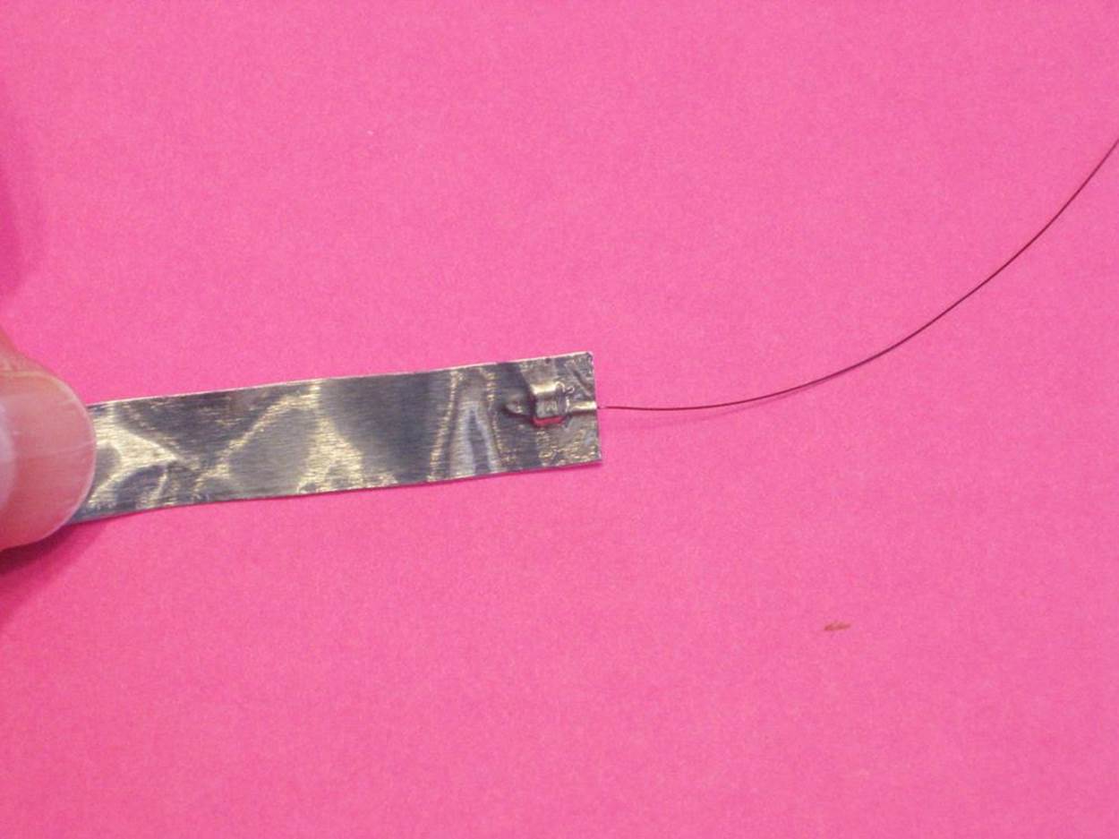
5. Take one of the narrow strips of foil you just made and cut it into two pieces, one 3 inches (8 cm) long and the other 2 1/2 inches (6 cm) long. Take one of these short pieces and peel off about half an inch (1.25 cm) of the backing. Now take one of the crimped wire ends and press it onto the exposed foil.
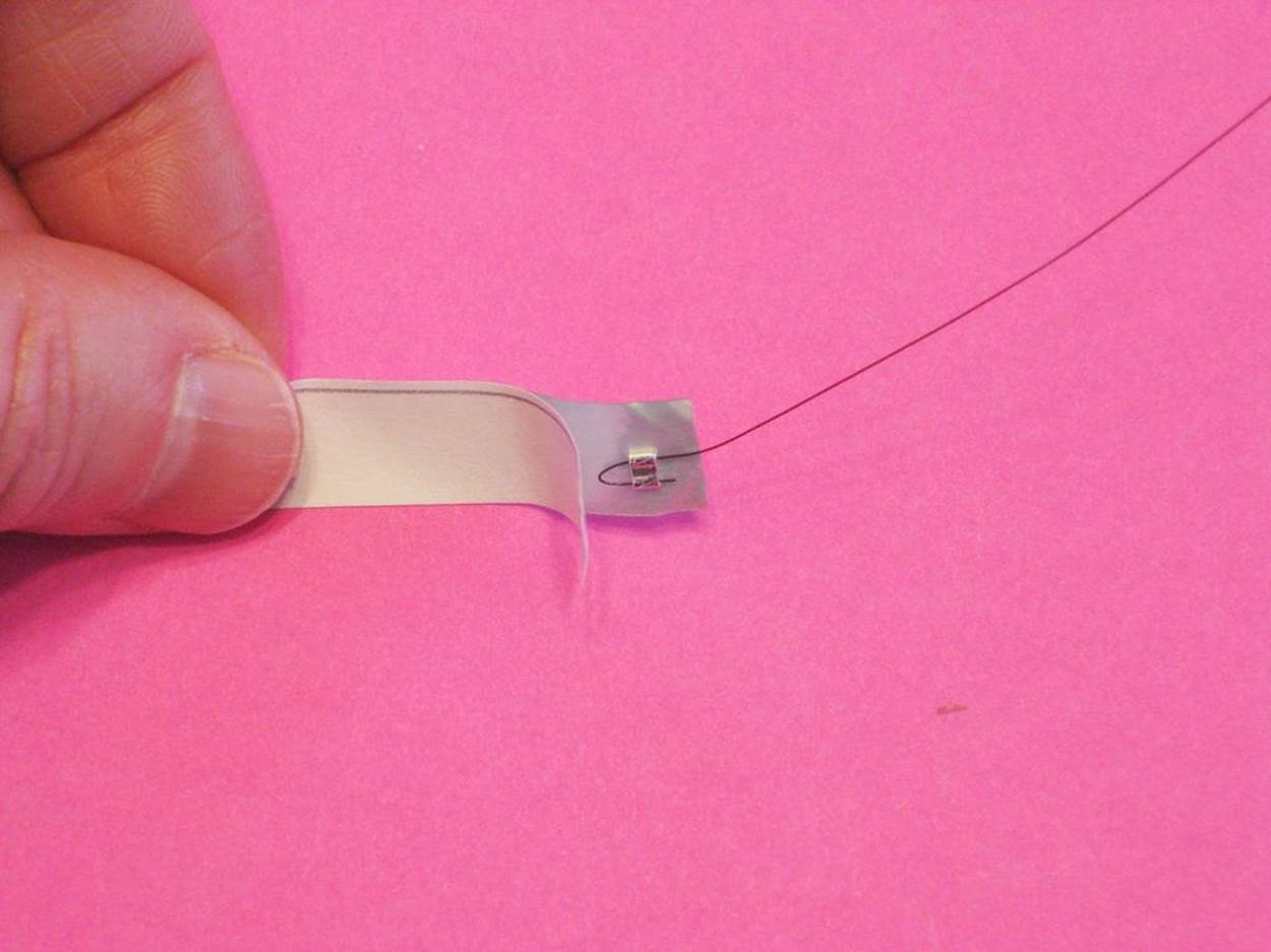
Close up the backing and squeeze to make a good connection between the wire and the foil. Do the same with the other short piece of foil and the other crimped wire end.
6. To make the base of your test platform, take a piece of letter-sized paper or cardstock and place it on the table in front of you, portrait-style. With the pen, make two marks side by side, 1/8 inch (3 mm) apart, just below the center of the page. Take one of the the foil strips holding the wire, and unpeel the flap of backing you exposed before. Press it onto the paper and slowly unpeel the rest of the back so that it does the same with the other piece of foil, placing it parallel to the first strip and leaving a small gap in between them. It’s OK if the loop of wire hangs off the top of the paper.
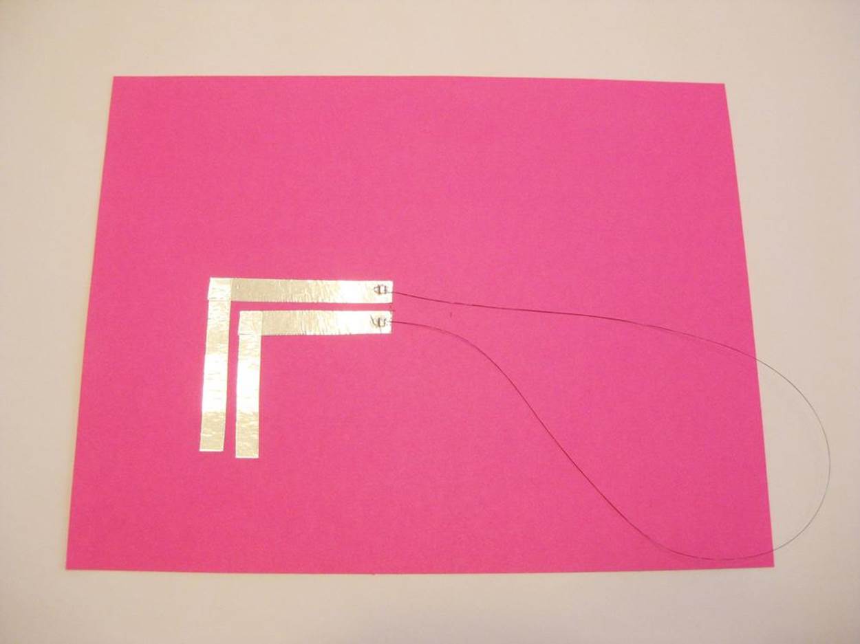
7. If you like, extend the circuit by continuing your double track of tape around the corner. Cut another strip of foil into two pieces, both the same size. Take one new piece and place it on top of the end of one of the first foil strips at a right angle. Peel off the backing and press hard to help secure the connection between the top and bottom pieces of foil. Do the same with the other piece of foil, again being careful to keep a gap between the tracks. You can continue on this way as far as you like—but be aware that glued connections like these are not always reliable. The tail end of a long winding foil trace may end up being more decorative than functional. The section closest to the SMA wire will still be usable, regardless.
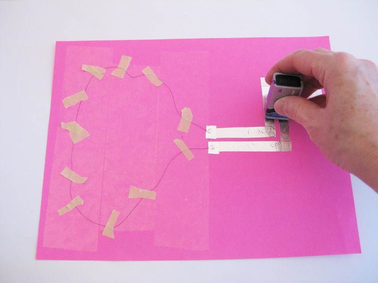
8. To protect the test platform from tearing when you attach and remove paper models, cover the upper area with a protective layer of tape. Start right above the foil strips to the top of the page. Wide, clear packing tape is best, although masking tape works, too. Just lay down strips of tape, one next to the other.
Step 5: Test Your Design
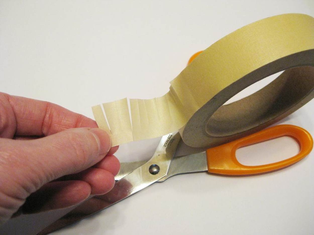
Before you start trying out different paper models, preheat the wire to make sure it’s working and let it stretch out a bit. Tack down the loop of wire to the test platform with several narrow strips of masking tape “bandages.” You can make these easily by unrolling a length of tape, cutting a fringe along one edge, and pulling off strips as needed. To use, press a bandage down across the wire, putting a little less pressure on the middle than on the ends, so the wire can move underneath. The masking tape bandages can be reused a couple of times to save time while you’re working. (You can also use a loop or tube of masking tape, sticky side out, to attach a paper model to the cardstock test platform.)
Make sure to secure the wire where the ends come together at the bottom, to prevent them from touching each other when they start to move.
Then take the 9V battery and briefly touch the terminals to the foil tracks. You should see the wire try to twist and curl. Lift the battery back up as soon as the movement is done—no longer than three or four seconds at a time. Too long and you risk overheating the SMA wire, which will de-program its shape-changing ability. When you’re ready, try actuating some paper models. Here are two simple examples:
Curling Flap
1. Take a piece of letter-sized copy paper and cut it in half, so that you end up with two pieces 8 1/2 by 5 1/2 inches (22 by 14 cm). (Save the other half for the next model.) Make a sticky-side out tube of masking tape and use it to attach the strip of paper near the bottom of the testing area of the platform, close to the foil. The flap should lay flat. It’s OK if it hangs off the top.
2. Lay the loop of SMA wire on top of the paper flap. Attach the wire to the flap with the little masking tape “bandages.” Place them across the wire, about 1/2 inch (1.25 cm) apart, closer around the top of the loop.
3. Touch the 9V battery to the foil traces. The flap should curl up, but it may also bend in a wave. You can change how it moves by playing around with the placement and number of the masking tape strips. You can also try creasing the flap in one or more places to see how that changes the movement of the paper.

PAPER ROBOTICS LINKBOX
Makezine Shape Memory Alloy How-To
Jie Qi
Robert J. Lang
UC Berkeley Biomimetic Millisystems Lab
DASH Robotics
Jeremy Shafer’s YouTube channel
Add a closing paper mouth to your project
NOTE
In origami-speak, “valley folds” go down and “mountain folds” go up.
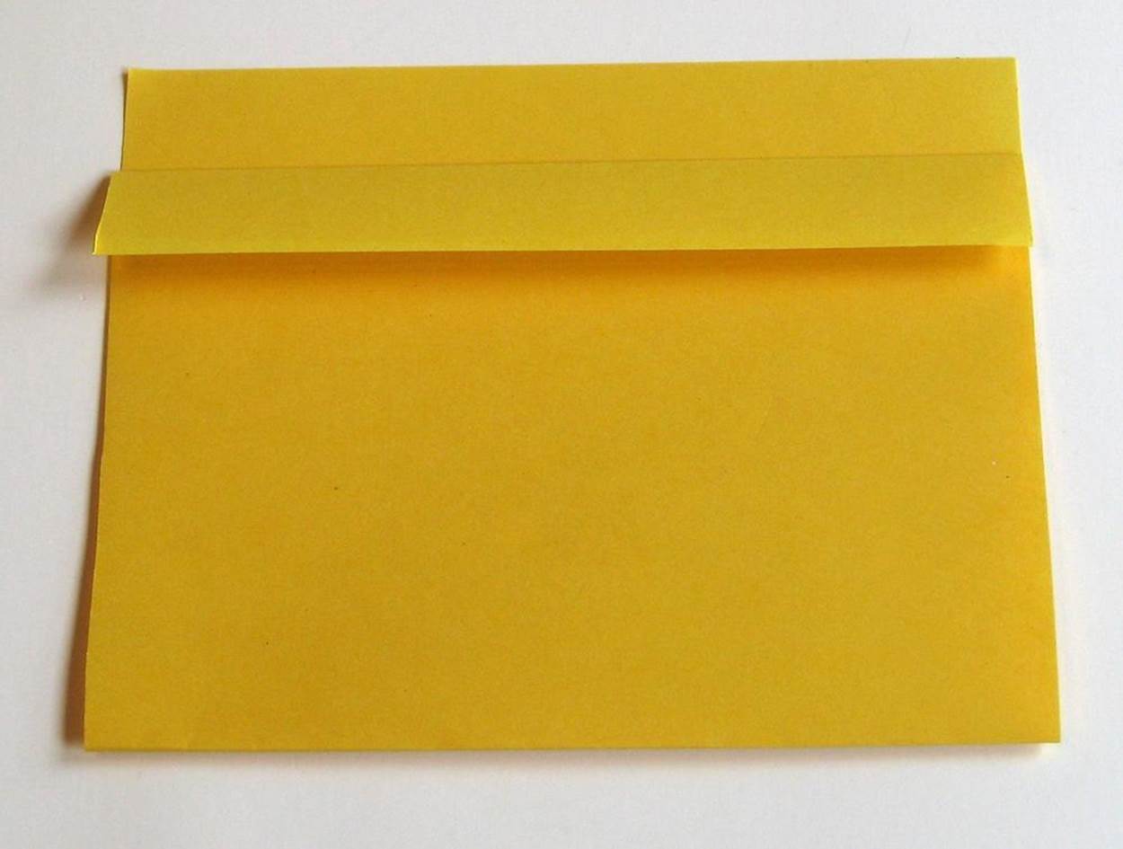
1. Start with a piece of copy paper 8 1/2 by 5 1/2 inches (22 by 14 cm). Place it portrait-style in front of you, and fold it in half by taking the bottom edge and bringing it to the top. Then take the upper edge and fold it down towards you about 3/4 inch (2 cm) from the top. Unfold it. Fold down one corner so that it lines up with the crease. Do the same with the other corner. Then flip the whole thing over and do the same with the other edge. Adjust the edges so that they stick out at right angles from the rest of the paper. These are the “lips” on the mouth.
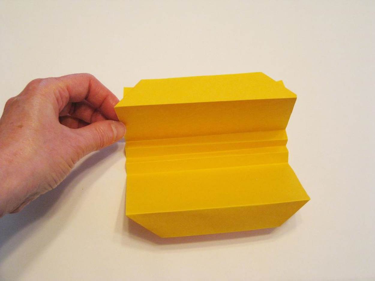
2. Turn the paper so that the fold is on the top. Fold it over again towards you about 1/2 inch (1.25 cm) from the top. Without unfolding it, flip the whole thing over and fold it over towards you one more time, the same amount. Unfold all the folds you just made and open the paper up so that the sides are pointing up in a crooked V shape. Adjust the creases so they go valley-mountain-valley-mountain-valley, like an accordion.
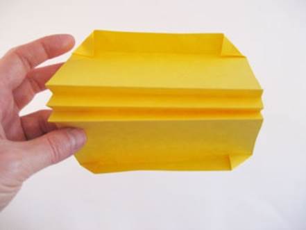
3. Close the model up and lay it on one side. You now have a paper “mouth” that wants to snap shut when you open it. Add two “eyes” by taking the top corners and folding the tips of them back up, so little triangles of paper are peeking out behind the diagonal folded corners.
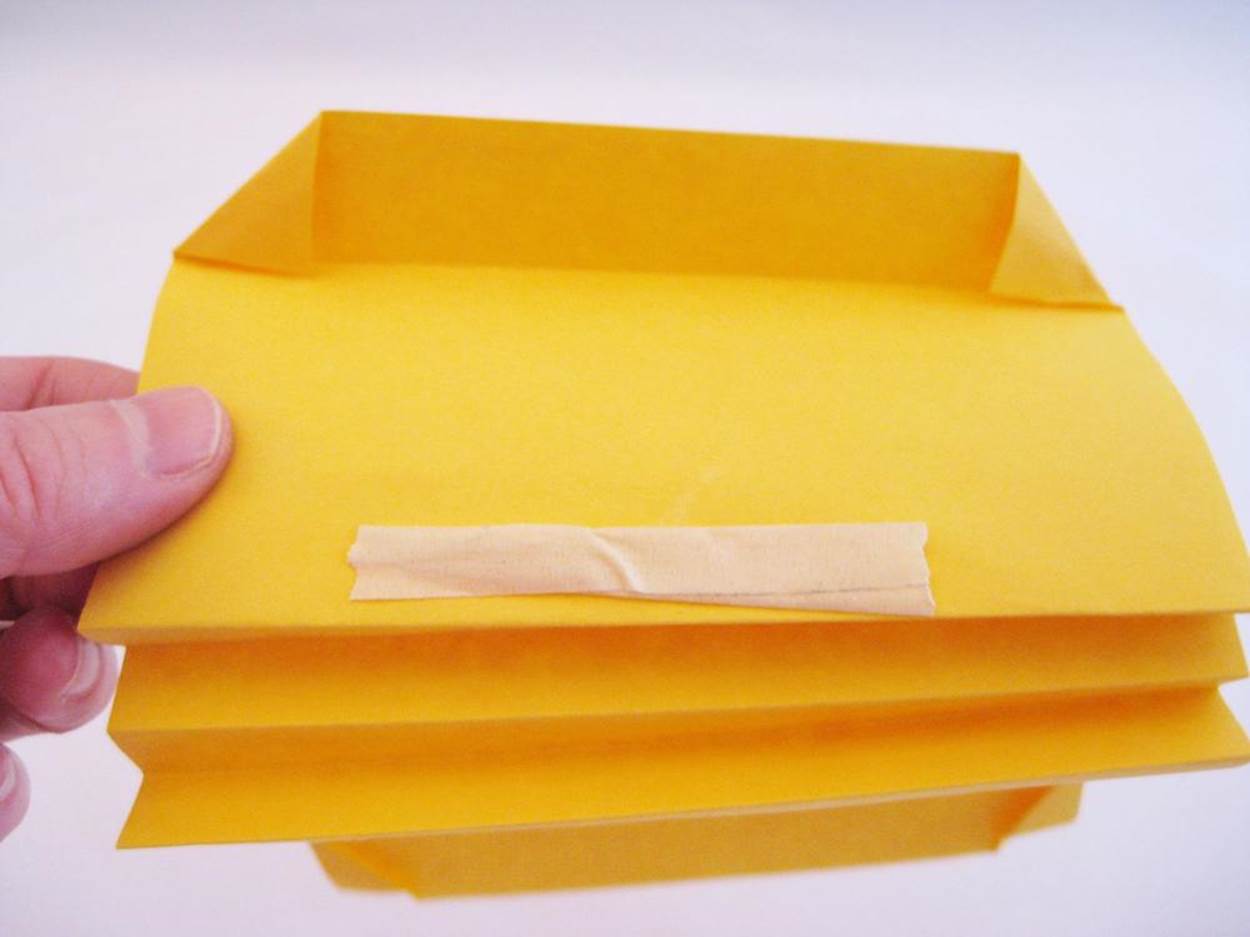
4. Form a tube out of a piece of masking tape, sticky-side-out, and put it along the bottom edge of the paper model, near the accordion fold. Attach the taped edge to the test platform so the mouth is facing away from the foil.
5. Use the thin masking tape bandages to attach the SMA wire loop to the top of the paper model. The wire should go up along the side edges, and across the top of the fold (on the outside). Tack down any extra wire to the testing platform.
6. Turn the testing platform around so the mouth is facing you. Take the 9V battery and touch it to the foil tracks. The mouth should slowly open. Lift the battery after a few seconds, and the mouth will slowly close, thanks to the springiness of the accordion fold.
Step 6: Troubleshoot and Refine
For maximum effect, keep the wire as taut as possible. If it stretches and loosens up, gently pull it down towards the foil traces, being careful not to break it. Then move the paper model itself further back towards the top of the platform, until the wire is as tight as it can be without wrinkling the paper it’s attached to.
If nothing happens when you touch the battery to the traces, try pressing down harder. If there are foil tape connections between the battery and the wire, try moving the battery so it’s touching the traces directly connected to the wire. If the tape connections seem to be at fault, try pressing them down firmly.
Be aware that this project will drain a 9V battery fairly quickly. If the experiment fails, especially if it had been working just a moment before, your battery may be running low. Try a fresh battery.
Step 7: Adaptations and Extensions
Actuated paper is an area of ongoing research. You can experiment with the test platform above by trying out different materials and components, such as:
Try paper that is heavier, lighter, stiffer, or more flexible
Square origami paper, which is lighter than copy paper, is an obvious choice. MIT’s Jie Qi built one of her actuated origami cranes using wax paper.
Experiment with different batteries, voltages, and diameters of SMA wire
Instead of a 9V battery, scrounge or buy a battery holder for two or more AA or AAA batteries, and try touching the wires lightly to the aluminum strips. Use the chart on the Dynalloy website to determine the current needed.
Make a more permanent actuated paper model
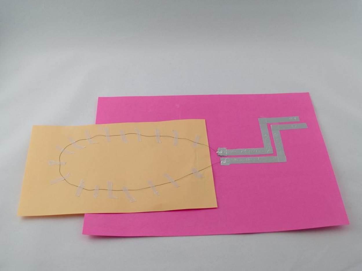
Instead of masking tape, attach the SMA wire to the paper model by sewing it on with cotton (or other nonconductive) thread. Make a series of small stitches diagonally or perpendicular across the wire. The wire will expand and contract a little more easily and still stay in place.
Play around with the resistance
Since aluminum foil isn’t a great conductor of electricity, the longer you make the traces, the more resistance you are adding to the circuit. That, of course, affects the current. Try touching the battery to the traces at different points to see what affect changes in current have on the performance of the SMA wire.
Make more reliable electrical connections
Instead of just overlapping two pieces of aluminum foil tape, try bending the end of the new piece under so that the nonglued side is touching the first piece. Secure it with an extra piece of tape. You can also try thin peel-and-stick copper tape (available from electronics retailers) and solder the connections together. (For directions on how to get started with soldering, see Project: Make a Souped-Up Solar BEAM Wobblebot. For more information on soldering metal tape, see Jie Qi’s website tutorials.)
CIRCUIT BASICS
There’s a lot to know about building electrical circuits, but the basic idea is this: in order for electricity to flow, it has to run in a loop or circle (hence the name circuit). Electricity is simply the movement of electrons from one atom to another. An atom, as you probably remember from science class, is one unit of an element, such as oxygen, helium, uranium, or copper. In the center of an atom is a nucleus made up of neutrons and positively charged protons, while negatively charged electrons circle around. A battery or solar cell supplies the force that starts the electrons flowing. For purposes of constructing an electrical circuit for the projects in this book, you can think of electricity as flowing out of the positive terminal (marked with a +) and running back into the negative terminal, or ground (marked with a –). The circuit generally includes a device to use the power being generated such as a light bulb or motor.
If you’ve never built a circuit from scratch before, you might want to try hooking up an LED bulb or DC (direct current) motor to a battery, just to get the hang of it (but read on before you try this). You can pick some up from any electronics website or your local RadioShack for a couple of dollars, but you can also rip them out of a dollar store keychain flashlight or old electric toothbrush. As you’ll quickly discover, LEDs are fickle. An unused LED usually has a longer leg, or lead, on the positive side, and a flat spot on the negative side of the bulb (an easy way to remember this is that the “plus” side has had something added to it, and the “minus” side has had something subtracted from it). If the leads are not connected to the battery in the right direction—positive lead to positive terminal, negative lead to negative terminal—the LED simply won’t light up. The DC motors you will use in this book work either way around, but whether the shaft turns clockwise or counterclockwise depends on which way the battery is facing.
Another thing you’ll also need to pay attention to in your circuit is the voltage and the current. Too little and your device won’t work. Too much, and you can overheat it. The voltage refers to the amount of energy available in the power source—or more accurately, to the difference in energy levels between two points in the circuit. The current, or amperage (measured in amperes or amps), indicates how much energy can flow in a certain amount of time. If you think of an electrical circuit as being something like a closed system of pipes filled with water, the voltage is the water pressure, and the current is how fast it flows.
Most LEDs will start to glow with just over 2 volts, and will usually burn out if you try to feed 9V into them. A 3V disc battery like you’d find in a watch should work fine for short bursts, Throwie style (see Break the Code: Throwies). For longer use, you’ll have to add a resistor to the circuit. A resistor is a small component that makes it harder for current to flow. In our water pipe analogy, the resistance would be the width of the pipes. The wider the pipe, the more water can flow through at one time. The SparkFun website has an electricity tutorial that gives you a good rule of thumb for using resistors with LEDs. They suggest trying a resistor rated at 330 ohms. If the resistance is too high, the LED won’t get as bright as it can, or the resistor will start to get warm. If that happens, just try a lower-rated resistor. If the resistance is too low, the LED will burn out, and you will need to find one with a little higher rating.
WARNING
Be very careful to avoid making a short circuit by connecting the battery to itself without some sort of device or resistor that will eat up some of the electricity in between. It will quickly overheat and if left too long, may explode or burst.
The other major thing your circuit will need is some kind of wiring to connect the various parts. For fooling-around purposes, you can build a circuit with any insulated wire you have on hand and a little electrical tape. A better tool for prototyping is a supply of short jumper wires with alligator clips on either end that will let you quickly make and take apart connections. For beginners, overlapping the ends of metallic tape is a quick-and-dirty way to make a circuit on paper. But for more reliable connections, soldering is the way to go.
BREAK THE CODE: THROWIES
The shortest LED circuit you can build is a Throwie. Just pinch a disc battery between the wires of an LED. They’re called Throwies because the original version included a small magnet, and were designed to be thrown onto a metal surface such as a bridge, pipe, or fire escape, where they would create an impromptu light-up display. Throwies were invented by Graffiti Research Lab in New York City in 2006, and became an instant real-life viral phenomenon after the group posted a how-to on the website Instructables.com.
ELECTRICAL CIRCUIT LINKBOX
SparkFun Circuit Tutorial
How Circuits Work
Science Buddies Electronics Primer
Make: Electronics by Charles Platt (2009, Maker Media)
Getting Started in Electronics by Forrest M. Mims III (2003, Master Publishing)
BREAK THE CODE: OHM’S LAW
If you ask an engineer or experienced maker about circuits, don’t be surprised if they start quoting Ohm’s Law at you. Ohm’s Law is an equation that describes the relationship between voltage, current, and resistance. For any given voltage, if the resistance goes up, the current goes down. Ohm’s Law says that you can figure out the exact amount of any of the three quantities by using the formula V = I × R, where V stands for the voltage in volts, I represents the current in amps, and R is the resistance in ohms. In other words, the voltage in a circuit equals the current multiplied by the resistance.
If there’s not enough resistance in the circuit, you’ll have too much current , and too much current can damage electrical components. Ohm’s Law is a handy rule to use if you want to figure out how much resistance you need to make your device run without frying it. So if you know the voltage in your circuit and what current the device will take, just plug the numbers into Ohm’s Law to get the right resistance.
You won’t need to do the math for any of the projects in this book, but if someone tries to explain Ohm’s Law to you, you’ll be able to smile and nod, because you’ll know what they’re talking about.
Project: Make an Inflatable Robot

An inflatable robot (or robotic body part) has a soft, stretchy outer surface and one or more air chambers inside. It can move or change shape by adjusting the amount of air it contains.
What It Does
Inflatable robots and robotic parts are cheap, lightweight, strong, and collapsible, making them easy to store or carry. Inflatable actuators, also known as air muscles or pneumatic artificial muscles, allow robots to move in a more natural way than gears and motors.
Where It Came From
If you’ve seen the Disney hit Big Hero 6 and its star Baymax, you know that soft, inflatable robots are all the rage. Real-life inflatable robots take their inspiration from the kind of air-filled objects we use every day. In California, inventor (and Make: magazine contributor) Saul Griffith and his company Otherlab make air-powered inflatables known as Pneubots (Figure 1-5) that look like elephantine beach toys. Their skin is similar to the material used to make bounce house–type trampolines and the air bladders inside were prototyped using rubber bicycle tubes. Pneubots are soft but strong; the giant-sized Ant-Roach model can easily transport several people on its back. In Massachusetts, iRobot—the same company that makes the Roomba home robovacuum—is working on inflatable military robots that can be folded flat when not in use and carried in a backpack. Baymax itself was inspired by an inflatable robot arm which was developed at Carnegie Mellon University in Pittsburgh to perform caregiving tasks like feeding disabled patients. And at Harvard, researchers are working on silicone robot grippers (Figure 1-6) that close their fingers and multilegged crawlers that can flex and move when air is pumped into specific inflatable chambers.
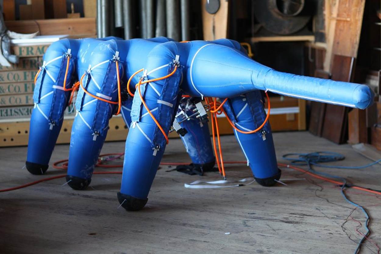
Figure 1-5. Soft, lightweight, and strong, Pneubotics are inflatable robots. Credit: Pneubotics, an Otherlab company.
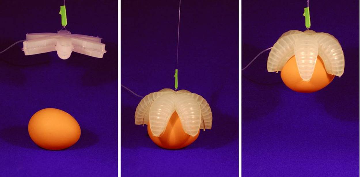
Figure 1-6. A silicon gripper, activated by inflating it with air, picks up a raw egg. Credit: Filip Ilievski, Whitesides Group, Harvard University (photo is CC BY-SA 4.0).
Air muscles were invented in 1957 by Joseph L. McKibben, a nuclear physicist at the atomic testing site in Los Alamos, New Mexico. McKibben was asked to develop an artificial muscle based on the design of real muscles to help people with weak limbs like his daughter, who suffered from polio. His design used a canister of carbon dioxide gas to expand and contract a rubber tube inside a woven fabric sleeve. The McKibben air muscle is extremely powerful, with the ability to pull 400 times its weight (compare that with a standard battery-powered DC motor, which at best can pull 16 times its weight). Today this style of artificial muscles is used in robotics research as well as for medical purposes.
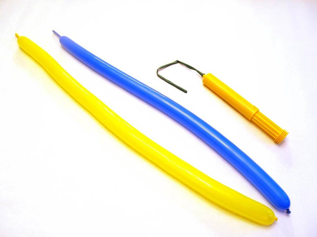
Most air muscles use rubber tubing, but mechanical engineering student Wyatt Felt created a version using ordinary twisting balloons—the kind used to make balloon animals. Felt’s design incorporated an electronically controlled electric air pump that could be programmed to inflate and deflate the robot muscles.
How It Works
Air muscles work by varying the air pressure inside. Like real muscles, they expand and contract in length. An inflatable robot’s ability to bend, twist, and stretch has to do with what’s on the outside, typically a stretchy material like fabric or rubber. Whether it’s hard or compliant depends on how much air or other gas you put into it. At lower pressures, there’s less gas inside and the gas molecules can move out of the way more easily when you press on them. The higher the air pressure inside, the more gas molecules you pack in, and the more rigid your inflatable structure becomes.
Think of the tires on a bicycle. Road bike tires, which are designed to get the best mileage on smooth roads, are usually inflated to 130 PSI (pounds per square inch, a unit of pressure). If filled to the correct pressure, a road bike tire is so hard you can’t make an indent by pressing on it with your thumb. Mountain bikes are designed to cushion the ride over uneven terrain without puncturing, so they’re normally inflated to a softer 30 to 50 PSI. The same principle applies to the Otherlab inflatable robot arm, which can lift as much as a human when the pressure is 200 PSI, but at 20 PSI, can only lift one-fifth the weight.
McKibben-style air muscles have a stretchable inner rubber tube nestled inside a braided mesh fabric sleeve. One end is sealed, and air is pumped in and sucked out through a valve at the other end. The mesh sleeve acts somewhat like a child’s Chinese finger puzzle—it gets tighter when stretched lengthwise and loosens when the ends are pushed together. When an air muscle is in the resting position, the mesh sleeve is long and thin, and the rubber tube inside is stretched along its length. Pump air into the rubber tube and it gets fatter. That widens the mesh sleeve and pulls the ends towards each other, making the whole muscle shorter.
The Harvard inflatable gripper, on the other hand, is basically a full-body muscle. Instead of large air chambers, its soft flat body contains narrow air channels. The starfish-shaped gripper is made by pouring liquid silicone rubber into a mold and letting it solidify. The result is a nearly solid but flexible body, filled with a network of air chambers that puff up and pull the body into a curved shape when inflated. Like the claw in an arcade game, the gripper is lowered over an object. Pump in some air, and its fingers curve down and grab whatever is below.
Wyatt Felt’s twisty balloon air muscle uses yet another way to move. It differs from the McKibben muscle in that it pushes instead of pulls. When deflated, Felt’s balloon air chamber is short and narrow. When activated, it expands in both length and width. Felt’s display model used an electronically controlled air pump with intake and outflow valves. The muscles were hooked up to “legs” made of curved pieces of plastic that straightened out when actuated by the muscle. But on his first prototype, both the leg structure and the air muscle were made from balloons, and air was supplied by a hand pump.
Making the Project
This project is based on the prototype twisting balloon air muscle created by Wyatt Felt, and adds a few twists of its own. Instead of legs that curve and straighten out, this version opens and closes a Sarrus linkage, a pair of hinges set at right angles to one another, similar to the ones used in pop-up paper robots like the RoACH. This adaptation of Felt’s air muscle also incorporates a built-in release valve mechanism that takes only a minute to create.
Project Parameters
§ Time Needed: 1 hour
§ Cost: Less than $10
§ Difficulty: Easy
§ Safety Issues: Watch out for popping balloons!
What You Need to Know
§ Skills You Already Have: Blowing up balloons
§ Skills You Will Learn: Balloon twisting techniques
Gather Your Materials
§ Twisting balloons (available in party goods stores
§ Balloon hand pump
§ Flexible vinyl, 1/4-inch (15 cm) diameter (available in hardware stores)
§ Electrical tape
§ Scissors
Directions
Step 1: List Your Requirements
The goal of this project is to make a soft, compliant robotic part using inflatable rubber materials for both body and actuator.
Step 2: Plan Your Project
This build doesn’t require a lot of planning, unless you want to get fancy and try one of the extensions below. Just make sure you have plenty of balloons on hand, since they are not as robust as other kinds of inflatable construction.
Step 3: Stop, Review, and Get Feedback
You will probably not be surprised to learn that people like MIT’s Erik Demaine have studied the math behind balloon twisting. You can learn more about it in papers by Demaine and “recreational mathemusician” Vi Hart (see Inflatable Robot Linkbox).
Step 4: Build Your Prototype
Follow these steps to build the muscle balloon:
1. Use the hand pump to inflate two balloons, leaving about 4 to 5 inches (10 to 12 cm) uninflated at the end. This is known as the tip of the balloon. Remove the pump and let out a little air (known in the business as burping the balloon). This bit of slack makes it easier to twist the balloon without popping it. Tie the neck of the balloon in a knot to seal it. Helpful hint: before inflating a balloon, stretch it lengthwise a few times.
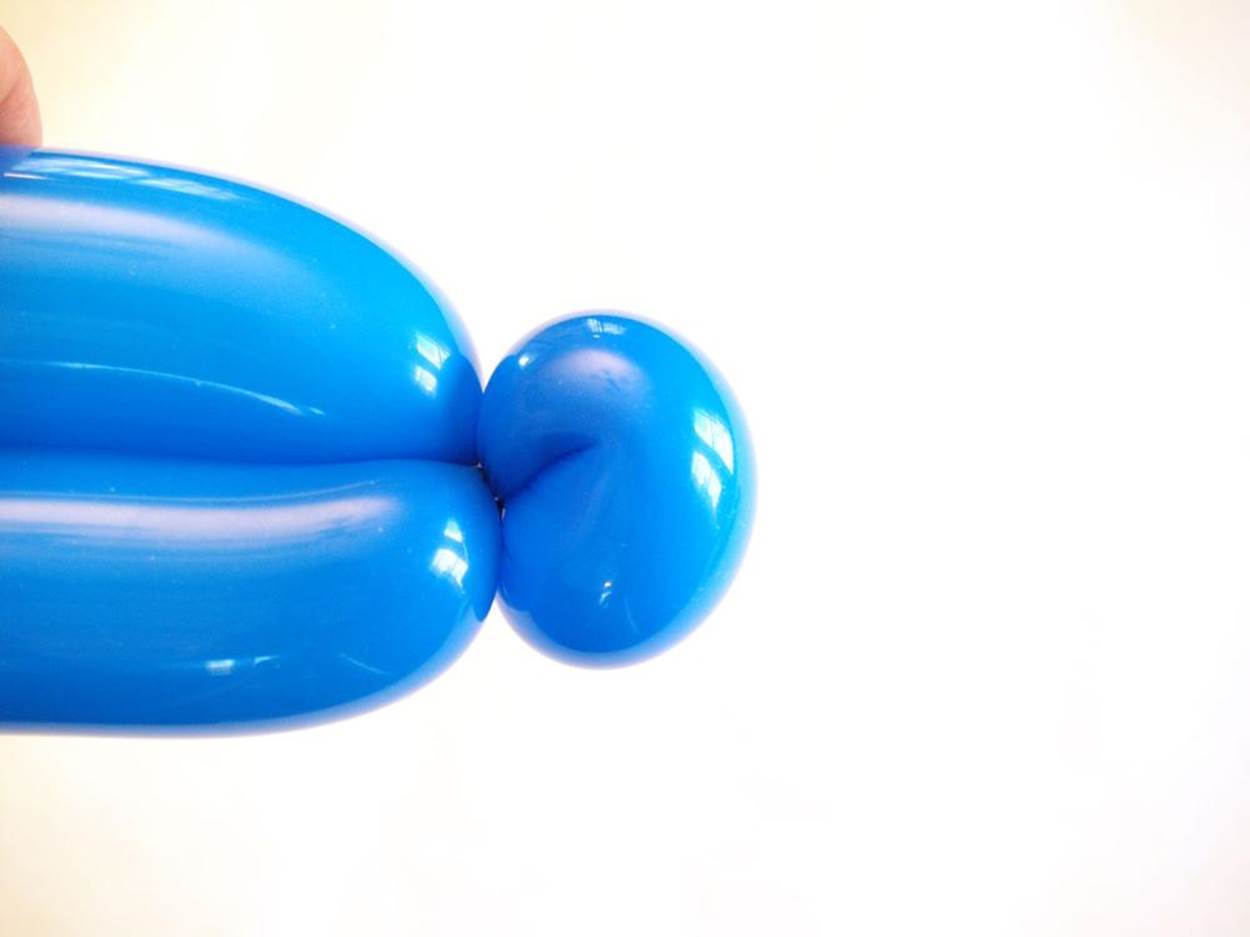
2. Take one of the balloons and pinch it gently about 3 inches (8 cm) from the knot. Twist it around three times. Do the same to the other balloon, then connect the two balloons by twisting them together where they are already twisted.

3. To make a hinge in the first balloon, bend it in half. At the bend, pinch a golf-ball-sized segment in your fingers.
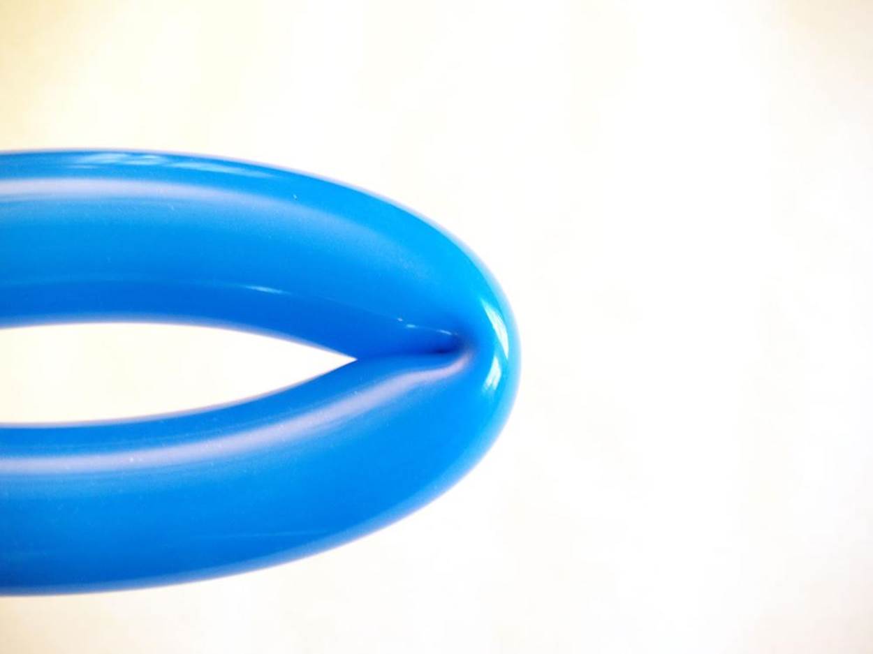
Twist it around three times, spinning it like a dial. Then circle it around the balloon itself until it reaches its starting point. The hinge should look like a knee sticking out in front. Do the same with the other balloon.
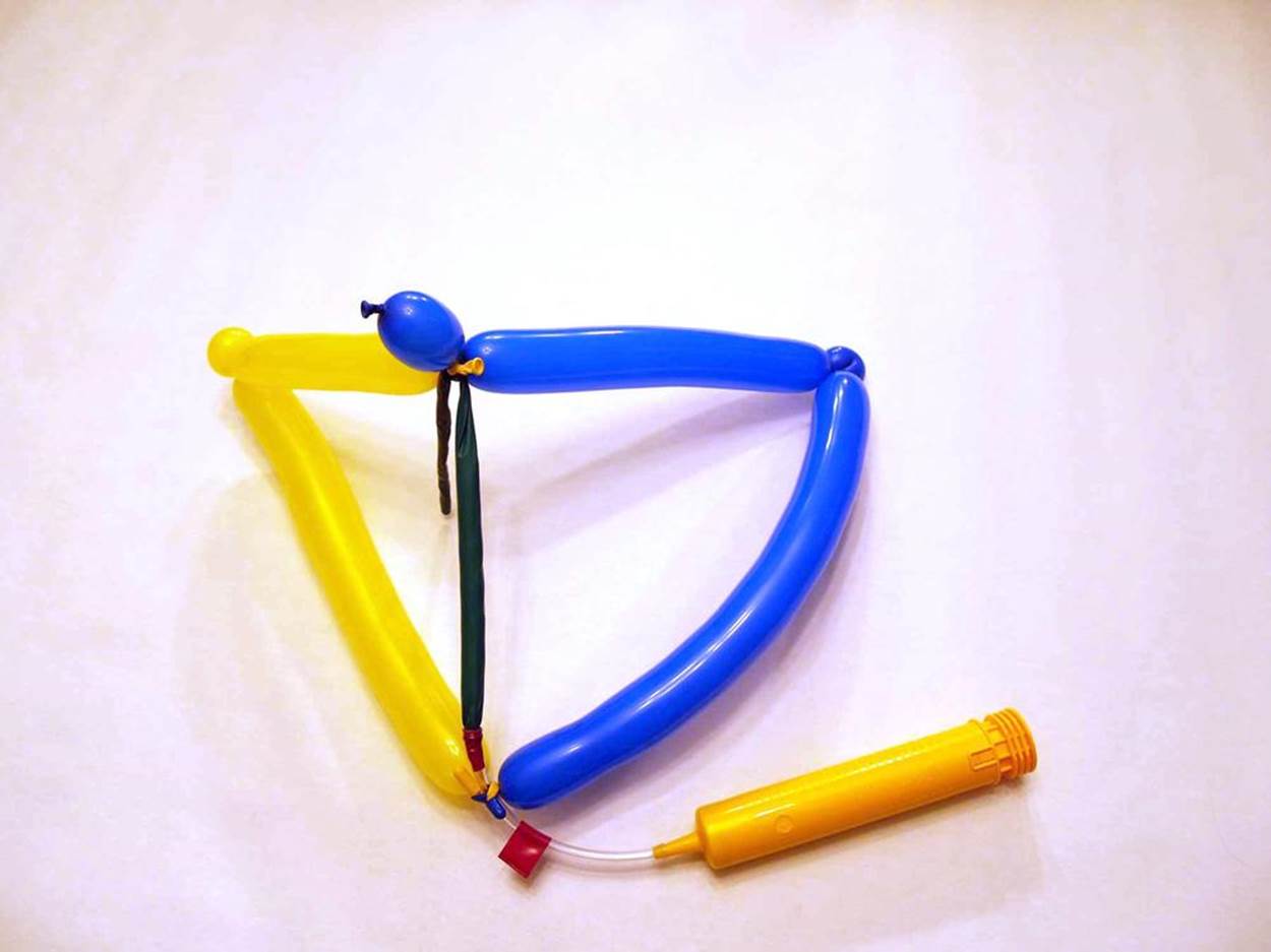
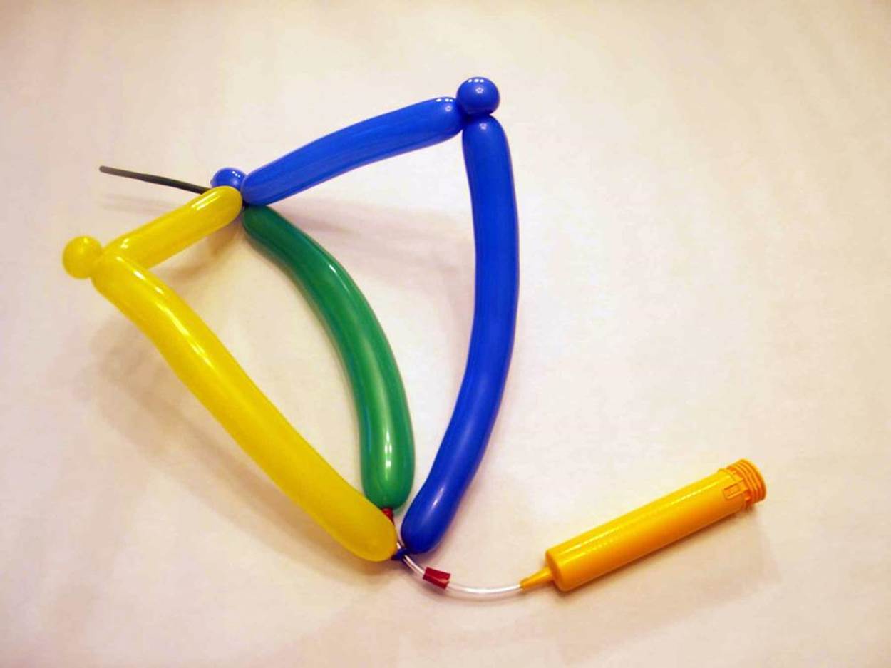
4. Tie the tips of the balloons together using the uninflated extra rubber. Tie another knot about half an inch (1 cm) above the first. The balloons will form a diamond shape with the hinges in the middle.
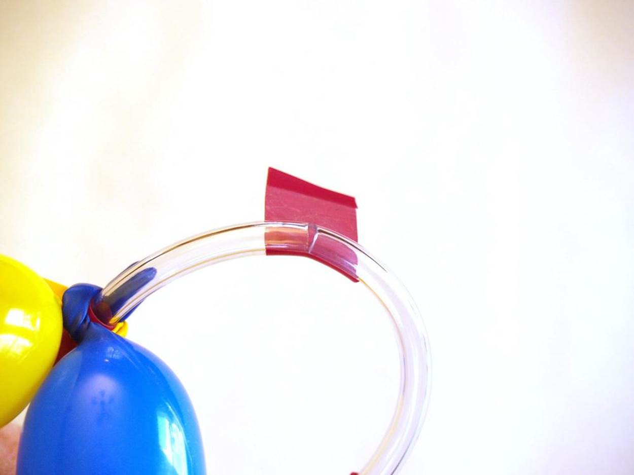
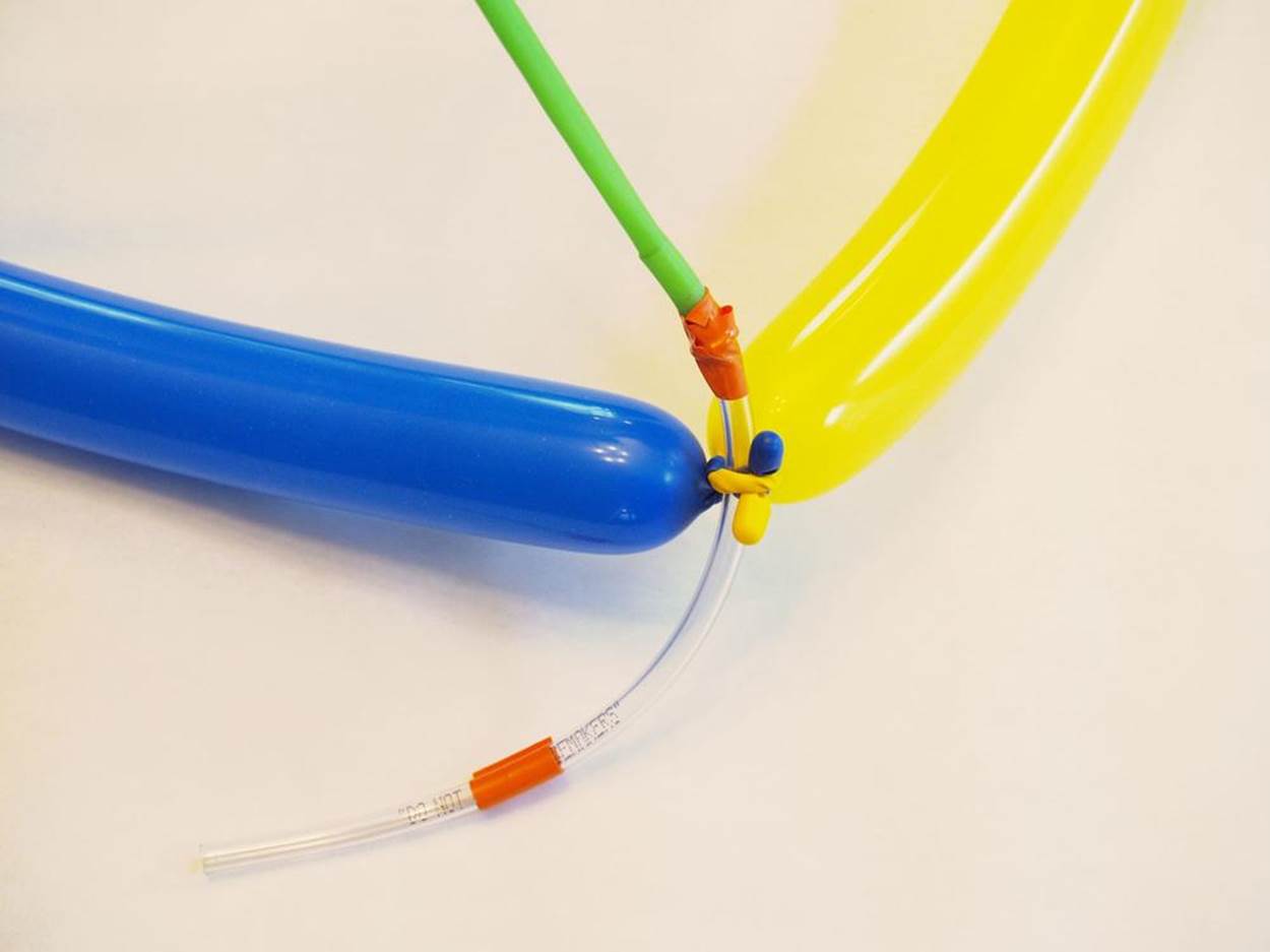
5. Now take the vinyl tubing and cut a piece 10 inches (25 cm) long. Make a release valve in the piece of tubing by taking the scissors or an art knife and cut a small slit about halfway down. Don’t let it go more than partway through the tubing. You should be able to bend the tubing back to open the slit without tearing the tubing. Take a piece of electrical tape about 2 inches (5 cm) long, and fold over a tiny bit at one end. Take the other end and wrap it around the tubing so it covers the slit. Use the folded-over end as a tab that you can pull back to reveal the slit. Try bending the tubing back so the slit opens up. Then reseal it with the tape. You can test it by inserting the air pump to make sure it is airtight when sealed.
6. Poke one end of the tubing through the gap between the two knots in Step 3. Take a third balloon, inflate it, then let the air out. This is your air muscle. Pull the opening of the air muscle balloon over the end of the tubing that pokes out between the knots. The balloon should cover about 1 inch (2 cm) of the tubing. Secure the balloon to the tubing with a piece of electrical tape.
7. Take the top and the bottom of the balloon diamond and press them towards each other. This is the movement your inflatable hinge will make. Decide how close you would like them to get, and tie the tip of the air muscle balloon to the tips of the other two balloons to hold them in this position.
8. Insert the end of the air pump into the other end of the clear tubing, as far as it will go. Secure it with more electrical tape if needed.
Step 5: Test Your Design
Use the pump to slowly and carefully inflate the muscle balloon. As it fills with air, it should lengthen and push the balloon hinge open. To let the hinge close up again, open the release valve by unwinding the tape enough to explore the slit, and bending the tubing back to widen the opening. The air should escape and the balloon should return to roughly the same length as when it started.
Step 6: Troubleshoot and Refine
If you’re having trouble inflating the balloon, test out your pump on another balloon fresh out of the package. Cheap pumps break easily. Also check your balloon for leaks.
Step 7: Adaptations and Extensions
Expand on the balloon body
Add a complete robot to the robotic body part with a torso, arms, and a head. (See Inflatable Robot Linkbox for a tutorial.) Or go abstract with a mathematical balloon model.
Make a splitter to actuate several robotic parts at once
Take a short piece of clear tubing and cut out a diamond shape big enough to fit another piece of tubing. Make as many holes as you want extra air lines. Insert another piece of clear tubing into each juncture. Seal around it with Sugru or with a hot glue gun to prevent leaks.
Try turning your balloon into a McKibben muscle
Insert a twisty balloon into a Chinese finger puzzle or short length of braided expandable sleeve (available as an electronics cable organizer or a fidget toy). A YouTube tutorial will show you how (see Inflatable Robot Linkbox).
Make a Harvard silicone gripper with a 3D printed mold
Read about 3D printing in Chapter 2, then check out the Instructable from Harvard-trained roboticist Ben Finio to make your own mold for creating an air-actuated silicone gripper.
INFLATABLE ROBOT LINKBOX
Wyatt Felt Twisty Balloon Pneumatic Actuator
Vi Hart on balloon math (PDF)
Basic balloon twists
Dylan Gelinas simple balloon robot tutorial
Phil Teare braided sleeve balloon McKibben muscle tutorial
Harvard silicone gripper Instructable