Introduction to 3D Game Programming with DirectX 12 (Computer Science) (2016)
|
Part 2 |
DIRECT3D
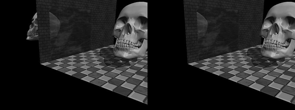
The stencil buffer is an off-screen buffer we can use to achieve some special effects. The stencil buffer has the same resolution as the back buffer and depth buffer, such that the ijth pixel in the stencil buffer corresponds with the ijth pixel in the back buffer and depth buffer. Recall from §4.1.5 that when a stencil buffer is specified, it comes attached to the depth buffer. As the name suggests, the stencil buffer works as a stencil and allows us to block the rendering of certain pixel fragments to the back buffer. For instance, when implementing a mirror, we need to reflect an object across the plane of the mirror; however, we only want to draw the reflection into the mirror. We can use the stencil buffer to block the rendering of the reflection unless it is being drawn into the mirror (see Figure 11.1).
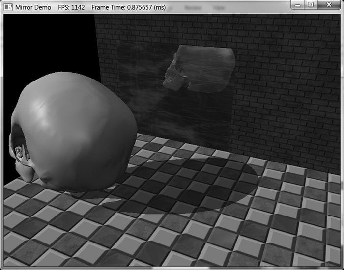
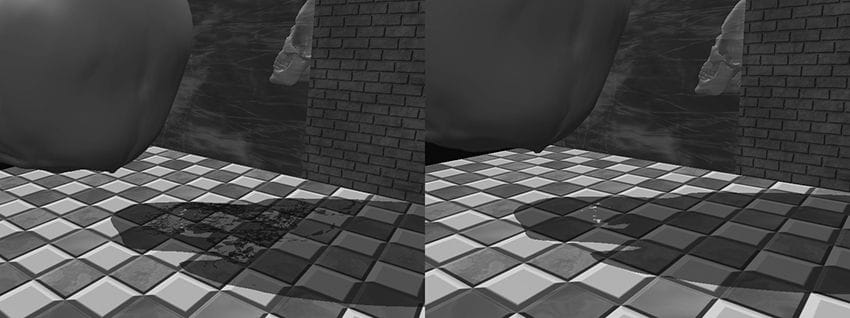
Figure 11.1. (Left) The reflected skull shows properly in the mirror. The reflection does not show through the wall bricks because it fails the depth test in this area. However, looking behind the wall we are able to see the reflection, thus breaking the illusion (the reflection should only show up through the mirror). (Right) By using the stencil buffer, we can block the reflected skull from being rendered unless it is being drawn in the mirror. The stencil buffer (and also the depth buffer) state is configured by filling out a D3D12_DEPTH_STENCIL_DESC instance and assigning it to the D3D12_GRAPHICS_PIPELINE_STATE_DESC::DepthStencilState field of a pipeline state object (PSO). Learning to use the stencil buffer effectively comes best by studying existing example application. Once you understand a few applications of the stencil buffer, you will have a better idea of how it can be used for your own specific needs. Objectives: 1. To find out how to control the depth and stencil buffer state by filling out the D3D12_DEPTH_STENCIL_DESC field in a pipeline state object. 2. To learn how to implement mirrors by using the stencil buffer to prevent reflections from being drawn to non-mirror surfaces. 3. To be able to identify double blending and understand how the stencil buffer can prevent it. 4. To explain depth complexity and describe two ways the depth complexity of a scene can to measured. 11.1 DEPTH/STENCIL FORMATS AND CLEARING Recalling that the depth/stencil buffer is a texture, it must be created with certain data formats. The formats used for depth/stencil buffering are as follows: 1. DXGI_FORMAT_D32_FLOAT_S8X24_UINT: Specifies a 32-bit floating-point depth buffer, with 8-bits (unsigned integer) reserved for the stencil buffer mapped to the [0, 255] range and 24-bits not used for padding. 2. DXGI_FORMAT_D24_UNORM_S8_UINT: Specifies an unsigned 24-bit depth buffer mapped to the [0, 1] range with 8-bits (unsigned integer) reserved for the stencil buffer mapped to the [0, 255] range. In our D3DApp framework, when we create the depth buffer, we specify: DXGI_FORMAT mDepthStencilFormat = DXGI_FORMAT_D24_UNORM_S8_UINT; depthStencilDesc.Format = mDepthStencilFormat; Also, the stencil buffer should be reset to some value at the beginning of each frame. This is done with the following method (which also clears the depth buffer): void ID3D12GraphicsCommandList::ClearDepthStencilView( D3D12_CPU_DESCRIPTOR_HANDLE DepthStencilView, D3D12_CLEAR_FLAGS ClearFlags, FLOAT Depth, UINT8 Stencil, UINT NumRects, const D3D12_RECT *pRects); 1. DepthStencilView: Descriptor to the view of the depth/stencil buffer we want to clear. 2. ClearFlags: Specify D3D12_CLEAR_FLAG_DEPTH to clear the depth buffer only; specify D3D12_CLEAR_FLAG_STENCIL to clear the stencil buffer only; specify D3D12_CLEAR_FLAG_DEPTH | D3D12_CLEAR_FLAG_STENCIL to clear both. 3. Depth: The float-value to set each pixel in the depth buffer to; it must be a floating point number x such that 0 ≤ x ≤ 1. 4. Stencil: The integer-value to set each pixel of the stencil buffer to; it must be an integer n such that 0 ≤ n ≤ 255. 5. NumRects: The number of rectangles in the array pRects points to. 6. pRects: An array of D3D12_RECTs marking rectangular regions on the depth/stencil buffer to clear; specify nullptr to clear the entire depth/stencil buffer. We have already been calling this method every frame in our demos. For example: mCommandList->ClearDepthStencilView(DepthStencilView(), D3D12_CLEAR_FLAG_DEPTH | D3D12_CLEAR_FLAG_STENCIL, 1.0f, 0, 0, nullptr); 11.2 THE STENCIL TEST As previously stated, we can use the stencil buffer to block rendering to certain areas of the back buffer. The decision to block a particular pixel from being written is decided by the stencil test, which is given by the following: if( StencilRef & StencilReadMask Value & StencilReadMask ) accept pixel else reject pixel The stencil test is performed as pixels get rasterized (i.e., during the output-merger stage), assuming stenciling is enabled, and takes two operands: 1. A left-hand-side (LHS) operand that is determined by ANDing an application-defined stencil reference value (StencilRef) with an application-defined masking value (StencilReadMask). 2. A right-hand-side (RHS) operand that is determined by ANDing the entry already in the stencil buffer of the particular pixel we are testing (Value) with an application-defined masking value (StencilReadMask). Note that the StencilReadMask is the same for the LHS and the RHS. The stencil test then compares the LHS with the RHS as specified an application-chosen comparison function , which returns a true or false value. We write the pixel to the back buffer if the test evaluates to true (assuming the depth test also passes). If the test evaluates to false, then we block the pixel from being written to the back buffer. And of course, if a pixel is rejected due to failing the stencil test, it is not written to the depth buffer either. The typedef enum D3D12_COMPARISON_FUNC { D3D12_COMPARISON_NEVER = 1, D3D12_COMPARISON_LESS = 2, D3D12_COMPARISON_EQUAL = 3, D3D12_COMPARISON_LESS_EQUAL = 4, D3D12_COMPARISON_GREATER = 5, D3D12_COMPARISON_NOT_EQUAL = 6, D3D12_COMPARISON_GREATER_EQUAL = 7, D3D12_COMPARISON_ALWAYS = 8, } D3D12_COMPARISON_FUNC; 1. D3D12_COMPARISON_NEVER: The function always returns false. 2. D3D12_COMPARISON_LESS: Replace 3. D3D12_COMPARISON_EQUAL: Replace 4. D3D12_COMPARISON_LESS_EQUAL: Replace 5. D3D12_COMPARISON_GREATER: Replace 6. D3D12_COMPARISON_NOT_EQUAL: Replace 7. D3D12_COMPARISON_GREATER_EQUAL: Replace 8. D3D12_COMPARISON_ALWAYS: The function always returns true. 11.3 DESCRIBING THE DEPTH/STENCIL STATE The depth/stencil state is described by filling out a D3D12_DEPTH_STENCIL_DESC instance: typedef struct D3D12_DEPTH_STENCIL_DESC { BOOL DepthEnable; // Default True // Default: D3D11_DEPTH_WRITE_MASK_ALL D3D12_DEPTH_WRITE_MASK DepthWriteMask; // Default: D3D11_COMPARISON_LESS D3D12_COMPARISON_FUNC DepthFunc; BOOL StencilEnable; // Default: False UINT8 StencilReadMask; // Default: 0xff UINT8 StencilWriteMask; // Default: 0xff D3D12_DEPTH_STENCILOP_DESC FrontFace; D3D12_DEPTH_STENCILOP_DESC BackFace; } D3D12_DEPTH_STENCIL_DESC; 11.3.1 Depth Settings 1. DepthEnable: Specify true to enable the depth buffering; specify false to disable it. When depth testing is disabled, the draw order matters, and a pixel fragment will be drawn even if it is behind an occluding object (review §4.1.5). If depth buffering is disabled, elements in the depth buffer are not updated either, regardless of the DepthWriteMask setting. 2. DepthWriteMask: This can be either D3D12_DEPTH_WRITE_MASK_ZERO or D3D12_DEPTH_WRITE_MASK_ALL, but not both. Assuming DepthEnable is set to true, D3D12_DEPTH_WRITE_MASK_ZERO disables writes to the depth buffer, but depth testing will still occur. D3D12_DEPTH_WRITE_MASK_ALL enables writes to the depth buffer; new depths will be written provided the depth and stencil test both pass. The ability to control depth reads and writes becomes necessary for implementing certain special effects. 3. DepthFunc: Specify one of the members of the D3D12_COMPARISON_FUNC enumerated type to define the depth test comparison function. Usually this is always D3D12_COMPARISON_LESS so that the usual depth test is performed, as described in §4.1.5. That is, a pixel fragment is accepted provided its depth value is less than the depth of the previous pixel written to the back buffer. But as you can see, Direct3D allows you to customize the depth test if necessary. 11.3.2 Stencil Settings 1. StencilEnable: Specify true to enable the stencil test; specify false to disable it. 2. StencilReadMask: The StencilReadMask used in the stencil test: if( StencilRef & StencilReadMask accept pixel else reject pixel The default does not mask any bits: #define D3D12_DEFAULT_STENCIL_READ_MASK ( 0xff ) 3. StencilWriteMask: When the stencil buffer is being updated, we can mask off certain bits from being written to with the write mask. For example, if you wanted to prevent the top 4 bits from being written to, you could use the write mask of 0x0f. The default value does not mask any bits: #define D3D12_DEFAULT_STENCIL_WRITE_MASK ( 0xff ) 4. FrontFace: A filled out D3D12_DEPTH_STENCILOP_DESC structure indicating how the stencil buffer works for front facing triangles. 5. BackFace: A filled out D3D12_DEPTH_STENCILOP_DESC structure indicating how the stencil buffer works for back facing triangles. typedef struct D3D12_DEPTH_STENCILOP_DESC { D3D12_STENCIL_OP StencilFailOp; // Default: D3D12_STENCIL_OP_KEEP D3D12_STENCIL_OP StencilDepthFailOp; // Default: D3D12_STENCIL_OP_KEEP D3D12_STENCIL_OP StencilPassOp; // Default: D3D12_STENCIL_OP_KEEP D3D12_COMPARISON_FUNC StencilFunc; // Default: D3D12_COMPARISON_ALWAYS } D3D12_DEPTH_STENCILOP_DESC; 1. StencilFailOp: A member of the D3D12_STENCIL_OP enumerated type describing how the stencil buffer should be updated when the stencil test fails for a pixel fragment. 2. StencilDepthFailOp: A member of the D3D12_STENCIL_OP enumerated type describing how the stencil buffer should be updated when the stencil test passes but the depth test fails for a pixel fragment. 3. StencilPassOp: A member of the D3D12_STENCIL_OP enumerated type describing how the stencil buffer should be updated when the stencil test and depth test both pass for a pixel fragment. 4. StencilFunc: A member of the D3D12_COMPARISON_FUNC enumerated type to define the stencil test comparison function. typedef enum D3D12_STENCIL_OP { D3D12_STENCIL_OP_KEEP = 1, D3D12_STENCIL_OP_ZERO = 2, D3D12_STENCIL_OP_REPLACE = 3, D3D12_STENCIL_OP_INCR_SAT = 4, D3D12_STENCIL_OP_DECR_SAT = 5, D3D12_STENCIL_OP_INVERT = 6, D3D12_STENCIL_OP_INCR = 7, D3D12_STENCIL_OP_DECR = 8 } D3D12_STENCIL_OP; 1. D3D12_STENCIL_OP_KEEP: Specifies to not change the stencil buffer; that is, keep the value currently there. 2. D3D12_STENCIL_OP_ZERO: Specifies to set the stencil buffer entry to zero. 3. D3D12_STENCIL_OP_REPLACE: Specifies to replaces the stencil buffer entry with the stencil-reference value (StencilRef) used in the stencil test. Note that the StencilRef value is set when we bind the depth/stencil state block to the rendering pipeline (§11.3.3). 4. D3D12_STENCIL_OP_INCR_SAT: Specifies to increment the stencil buffer entry. If the incremented value exceeds the maximum value (e.g., 255 for an 8-bit stencil buffer), then we clamp the entry to that maximum. 5. D3D12_STENCIL_OP_DECR_SAT: Specifies to decrement the stencil buffer entry. If the decremented value is less than zero, then we clamp the entry to zero. 6. D3D12_STENCIL_OP_INVERT: Specifies to invert the bits of the stencil buffer entry. 7. D3D12_STENCIL_OP_INCR: Specifies to increment the stencil buffer entry. If the incremented value exceeds the maximum value (e.g., 255 for an 8-bit stencil buffer), then we wrap to 0. 8. D3D12_STENCIL_OP_DECR: Specifies to decrement the stencil buffer entry. If the decremented values is less than zero, then we wrap to the maximum allowed value.
11.3.3 Creating and Binding a Depth/Stencil State Once we have fully filled out a D3D12_DEPTH_STENCIL_DESC instance describing our depth/stencil state, we can assign it to the D3D12_GRAPHICS_PIPELINE_STATE_DESC::DepthStencilState field of a PSO. Any geometry drawn with this PSO will be rendered with the depth/stencil settings of the PSO. One detail we have not mentioned yet is how to set the stencil reference value. The stencil reference value is set with the ID3D12GraphicsCommandList::OMSetStencilRef method, which takes a single unsigned integer parameter; for example, the following sets the stencil reference value to 1: mCommandList->OMSetStencilRef(1); 11.4 IMPLEMENTING PLANAR MIRRORS Many surfaces in nature serve as mirrors and allow us to see the reflections of objects. This section describes how we can simulate mirrors for our 3D applications. Note that for simplicity, we reduce the task of implementing mirrors to planar surfaces only. For instance, a shiny car can display a reflection; however, a car’s body is smooth, round, and not planar. Instead, we render reflections such as those that are displayed in a shiny marble floor or those that are displayed in a mirror hanging on a wall—in other words, mirrors that lie on a plane. Implementing mirrors programmatically requires us to solve two problems. First, we must learn how to reflect an object about an arbitrary plane so that we can draw the reflection correctly. Second, we must only display the reflection in a mirror, that is, we must somehow “mark” a surface as a mirror and then, as we are rendering, only draw the reflected object if it is in a mirror. Refer back to Figure 11.1, which first introduced this concept. The first problem is easily solved with some analytical geometry, and is discussed in Appendix C. The second problem can be solved using the stencil buffer. 11.4.1 Mirror Overview
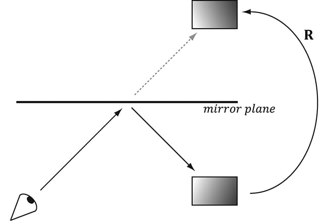
Figure 11.2 shows that to draw a reflection of an object, we just need to reflect it over the mirror plane. However, this introduces the problem shown in Figure 11.1. Namely, the reflection of the object (the skull in this case) is just another object in our scene, and if nothing is occluding it, then the eye will see it. However, the reflection should only be seen through the mirror. We can solve this problem using the stencil buffer because the stencil buffer allows us to block rendering to certain areas on the back buffer. Thus we can use the stencil buffer to block the rendering of the reflected skull if it is not being rendered into the mirror. The following outlines the step of how this can be accomplished:
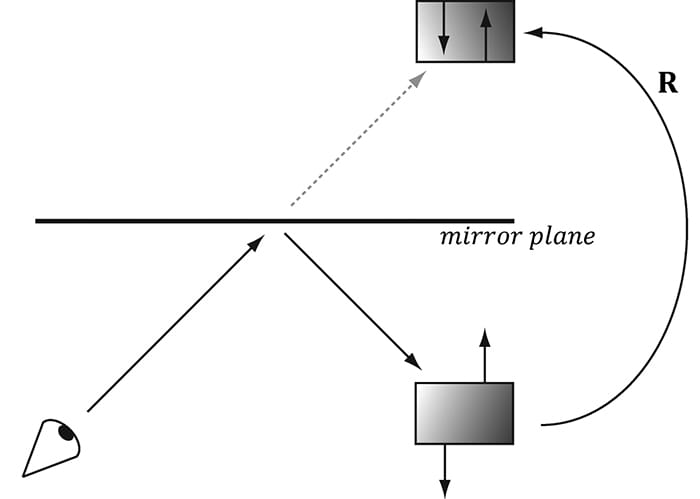
Figure 11.2. The eye sees the box reflection through the mirror. To simulate this, we reflect the box across the mirror plane and render the reflected box as usual.
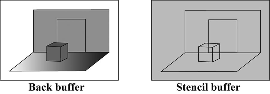
Figure 11.3. The floor, walls, and skull to the back buffer and the stencil buffer cleared to 0 (denoted by light gray color). The black outlines drawn on the stencil buffer illustrate the relationship between the back buffer pixels and the stencil buffer pixels—they do not indicate any data drawn on the stencil buffer. 1. Render the floor, walls, and skull to the back buffer as normal (but not the mirror). Note that this step does not modify the stencil buffer. 2. Clear the stencil buffer to 0. Figure 11.3 shows the back buffer and stencil buffer at this point (where we substitute a box for the skull to make the drawing simpler). 3. Render the mirror only to the stencil buffer. We can disable color writes to the back buffer by creating a blend state that sets D3D12_RENDER_TARGET_BLEND_DESC::RenderTargetWriteMask = 0; and we can disable writes to the depth buffer by setting D3D12_DEPTH_STENCIL_DESC::DepthWriteMask = D3D12_DEPTH_WRITE_MASK_ZERO; When rendering the mirror to the stencil buffer, we set the stencil test to always succeed (D3D12_COMPARISON_ALWAYS) and specify that the stencil buffer entry should be replaced (D3D12_STENCIL_OP_REPLACE) with 1 (StencilRef) if the test passes. If the depth test fails, we specify D3D12_STENCIL_OP_KEEP so that the stencil buffer is not changed if the depth test fails (this can happen, for example, if the skull obscures part of the mirror). Since we are only rendering the mirror to the stencil buffer, it follows that all the pixels in the stencil buffer will be 0 except for the pixels that correspond to the visible part of the mirror—they will have a 1. Figure 11.4 shows the updated stencil buffer. Essentially, we are marking the visible pixels of the mirror in the stencil buffer.
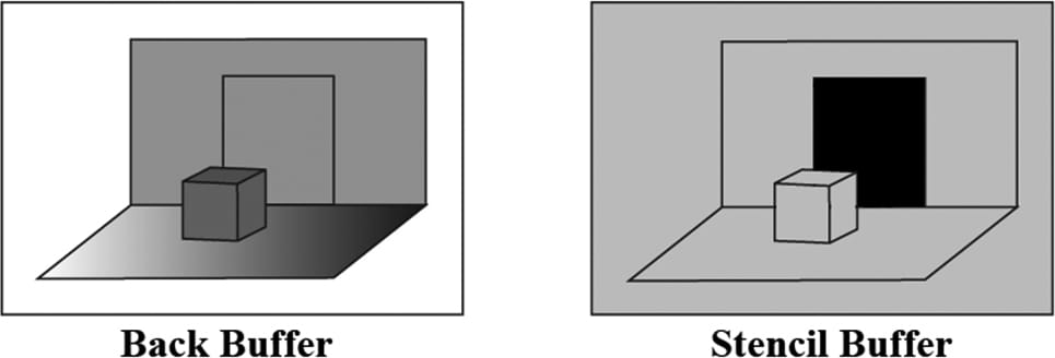
Figure 11.4. Rendering the mirror to the stencil buffer, essentially marking the pixels in the stencil buffer that correspond to the visible parts of the mirror. The solid black area on the stencil buffer denotes stencil entries set to 1. Note that the area on the stencil buffer occluded by the box does not get set to 1 since it fails the depth test (the box is in front of that part of the mirror).
4. Now we render the reflected skull to the back buffer and stencil buffer. But recall that we only will render to the back buffer if the stencil test passes. This time, we set the stencil test to only succeed if the value in the stencil buffer equals 1; this is done using a StencilRef of 1, and the stencil operator D3D12_COMPARISON_EQUAL. In this way, the reflected skull will only be rendered to areas that have a 1 in their corresponding stencil buffer entry. Since the areas in the stencil buffer that correspond to the visible parts of the mirror are the only entries that have a 1, it follows that the reflected skull will only be rendered into the visible parts of the mirror. 5. Finally, we render the mirror to the back buffer as normal. However, in order for the skull reflection to show through (which lies behind the mirror), we need to render the mirror with transparency blending. If we did not render the mirror with transparency, the mirror would simply occlude the reflection since its depth is less than that of the reflection. To implement this, we simply need to define a new material instance for the mirror; we set the alpha channel of the diffuse component to 0.3 to make the mirror 30% opaque, and we render the mirror with the transparency blend state as described in the last chapter (§10.5.4). auto icemirror = std::make_unique<Material>(); icemirror->Name = "icemirror"; icemirror->MatCBIndex = 2; icemirror->DiffuseSrvHeapIndex = 2; icemirror->DiffuseAlbedo = XMFLOAT4(1.0f, 1.0f, 1.0f, 0.3f); icemirror->FresnelR0 = XMFLOAT3(0.1f, 0.1f, 0.1f); icemirror->Roughness = 0.5f; These settings give the following blending equation:
Assuming we have laid down the reflected skull pixels to the back buffer, we see 30% of the color comes from the mirror (source) and 70% of the color comes from the skull (destination). 11.4.2 Defining the Mirror Depth/Stencil States To implement the previously described algorithm, we need two PSOs. The first is used when drawing the mirror to mark the mirror pixels on the stencil buffer. The second is used to draw the reflected skull so that it is only drawn into the visible parts of the mirror. // // PSO for marking stencil mirrors. // // Turn off render target writes. CD3DX12_BLEND_DESC mirrorBlendState(D3D12_DEFAULT); mirrorBlendState.RenderTarget[0].RenderTargetWriteMask = 0; D3D12_DEPTH_STENCIL_DESC mirrorDSS; mirrorDSS.DepthEnable = true; mirrorDSS.DepthWriteMask = D3D12_DEPTH_WRITE_MASK_ZERO; mirrorDSS.DepthFunc = D3D12_COMPARISON_FUNC_LESS; mirrorDSS.StencilEnable = true; mirrorDSS.StencilReadMask = 0xff; mirrorDSS.StencilWriteMask = 0xff; mirrorDSS.FrontFace.StencilFailOp = D3D12_STENCIL_OP_KEEP; mirrorDSS.FrontFace.StencilDepthFailOp = D3D12_STENCIL_OP_KEEP; mirrorDSS.FrontFace.StencilPassOp = D3D12_STENCIL_OP_REPLACE; mirrorDSS.FrontFace.StencilFunc = D3D12_COMPARISON_FUNC_ALWAYS; // We are not rendering backfacing polygons, so these settings do not // matter. mirrorDSS.BackFace.StencilFailOp = D3D12_STENCIL_OP_KEEP; mirrorDSS.BackFace.StencilDepthFailOp = D3D12_STENCIL_OP_KEEP; mirrorDSS.BackFace.StencilPassOp = D3D12_STENCIL_OP_REPLACE; mirrorDSS.BackFace.StencilFunc = D3D12_COMPARISON_FUNC_ALWAYS; D3D12_GRAPHICS_PIPELINE_STATE_DESC markMirrorsPsoDesc = opaquePsoDesc; markMirrorsPsoDesc.BlendState = mirrorBlendState; markMirrorsPsoDesc.DepthStencilState = mirrorDSS; ThrowIfFailed(md3dDevice->CreateGraphicsPipelineState( &markMirrorsPsoDesc, IID_PPV_ARGS(&mPSOs["markStencilMirrors"]))); // // PSO for stencil reflections. // D3D12_DEPTH_STENCIL_DESC reflectionsDSS; reflectionsDSS.DepthEnable = true; reflectionsDSS.DepthWriteMask = D3D12_DEPTH_WRITE_MASK_ALL; reflectionsDSS.DepthFunc = D3D12_COMPARISON_FUNC_LESS; reflectionsDSS.StencilEnable = true; reflectionsDSS.StencilReadMask = 0xff; reflectionsDSS.StencilWriteMask = 0xff; reflectionsDSS.FrontFace.StencilFailOp = D3D12_STENCIL_OP_KEEP; reflectionsDSS.FrontFace.StencilDepthFailOp = D3D12_STENCIL_OP_KEEP; reflectionsDSS.FrontFace.StencilPassOp = D3D12_STENCIL_OP_KEEP; reflectionsDSS.FrontFace.StencilFunc = D3D12_COMPARISON_FUNC_EQUAL; // We are not rendering backfacing polygons, so these settings do not // matter. reflectionsDSS.BackFace.StencilFailOp = D3D12_STENCIL_OP_KEEP; reflectionsDSS.BackFace.StencilDepthFailOp = D3D12_STENCIL_OP_KEEP; reflectionsDSS.BackFace.StencilPassOp = D3D12_STENCIL_OP_KEEP; reflectionsDSS.BackFace.StencilFunc = D3D12_COMPARISON_FUNC_EQUAL; D3D12_GRAPHICS_PIPELINE_STATE_DESC drawReflectionsPsoDesc = opaquePsoDesc; drawReflectionsPsoDesc.DepthStencilState = reflectionsDSS; drawReflectionsPsoDesc.RasterizerState.CullMode = D3D12_CULL_MODE_BACK; drawReflectionsPsoDesc.RasterizerState.FrontCounterClockwise = true; ThrowIfFailed(md3dDevice->CreateGraphicsPipelineState( &drawReflectionsPsoDesc, IID_PPV_ARGS(&mPSOs["drawStencilReflections"]))); 11.4.3 Drawing the Scene The following code outlines our draw method. We have omitted irrelevant details, such as setting constant buffer values, for brevity and clarity (see the example code for the full details). // Draw opaque items--floors, walls, skull. auto passCB = mCurrFrameResource->PassCB->Resource(); mCommandList->SetGraphicsRootConstantBufferView(2, passCB->GetGPUVirtualAddress()); DrawRenderItems(mCommandList.Get(), mRitemLayer[(int)RenderLayer::Opaque]); // Mark the visible mirror pixels in the stencil buffer with the value 1 mCommandList->OMSetStencilRef(1); mCommandList->SetPipelineState(mPSOs["markStencilMirrors"].Get()); DrawRenderItems(mCommandList.Get(), mRitemLayer[(int)RenderLayer::Mirrors]); // Draw the reflection into the mirror only (only for pixels where the // stencil buffer is 1). // Note that we must supply a different per-pass constant buffer--one // with the lights reflected. mCommandList->SetGraphicsRootConstantBufferView(2, passCB->GetGPUVirtualAddress() + 1 * passCBByteSize); mCommandList->SetPipelineState(mPSOs["drawStencilReflections"].Get()); DrawRenderItems(mCommandList.Get(), mRitemLayer[(int)RenderLayer::Reflected]); // Restore main pass constants and stencil ref. mCommandList->SetGraphicsRootConstantBufferView(2, passCB->GetGPUVirtualAddress()); mCommandList->OMSetStencilRef(0); // Draw mirror with transparency so reflection blends through. mCommandList->SetPipelineState(mPSOs["transparent"].Get()); DrawRenderItems(mCommandList.Get(), mRitemLayer[(int)RenderLayer::Transparent]); One point to note in the above code is how we change the per-pass constant buffer when drawing the RenderLayer::Reflected layer. This is because the scene lighting also needs to get reflected when drawing the reflection. The lights are stored in a per-pass constant buffer, so we create an additional per-pass constant buffer that stores the reflected scene lighting. The per-pass constant buffer used for drawing reflections is set in the following method: PassConstants StencilApp::mMainPassCB; PassConstants StencilApp::mReflectedPassCB; void StencilApp::UpdateReflectedPassCB(const GameTimer& gt) { mReflectedPassCB = mMainPassCB; XMVECTOR mirrorPlane = XMVectorSet(0.0f, 0.0f, 1.0f, 0.0f); // xy plane XMMATRIX R = XMMatrixReflect(mirrorPlane); // Reflect the lighting. for(int i = 0; i < 3; ++i) { XMVECTOR lightDir = XMLoadFloat3(&mMainPassCB.Lights[i].Direction); XMVECTOR reflectedLightDir = XMVector3TransformNormal(lightDir, R); XMStoreFloat3(&mReflectedPassCB.Lights[i].Direction, reflectedLightDir); } // Reflected pass stored in index 1 auto currPassCB = mCurrFrameResource->PassCB.get(); currPassCB->CopyData(1, mReflectedPassCB); } 11.4.4 Winding Order and Reflections When a triangle is reflected across a plane, its winding order does not reverse, and thus, its face normal does not reverse. Hence, outward facing normals become inward facing normals (see Figure 11.5), after reflection. To correct this, we tell Direct3D to interpret triangles with a counterclockwise winding order as front-facing and triangles with a clockwise winding order as back-facing (this is the opposite of our usual convention—§5.10.2). This effectively reflects the normal directions so that they are outward facing after reflection. We reverse the winding order convention by setting the following rasterizer properties in the PSO: drawReflectionsPsoDesc.RasterizerState.FrontCounterClockwise = true;
Figure 11.5. The polygon normals do not get reversed with reflection, which makes them inward facing after reflection. 11.5 IMPLEMENTING PLANAR SHADOWS
Shadows aid in our perception of where light is being emitted in a scene and ultimately makes the scene more realistic. In this section, we will show how to implement planar shadows; that is, shadows that lie on a plane (see Figure 11.6).
Figure 11.6. The main light source casts a planar shadow in the “Mirror” demo. To implement planar shadows, we must first find the shadow an object casts to a plane and model it geometrically so that we can render it. This can easily be done with some 3D math. We then render the triangles that describe the shadow with a black material at 50% transparency. Rendering the shadow like this can introduce some rendering artifacts called “double blending,” which we explain in a few sections; we utilize the stencil buffer to prevent double blending from occurring.
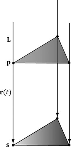
Figure 11.7. The shadow cast with respect to a parallel light source. 11.5.1 Parallel Light Shadows Figure 11.7 shows the shadow an object casts with respect to a parallel light source. Given a parallel light source with direction L, the light ray that passes through a vertex p is given by r(t) = p + tL. The intersection of the ray r(t) with the shadow plane (n, d) gives s. (The reader can read more about rays and planes in Appendix C.) The set of intersection points found by shooting a ray through each of the object’s vertices with the plane defines the projected geometry of the shadow. For a vertex p, its shadow projection is given by
The details of the ray/plane intersection test are given in Appendix C. Equation 11.1 can be written in terms of matrices.
We call the preceding 4 × 4 matrix the directional shadow matrix and denote it by Sdir. To see how this matrix is equivalent to Equation 11.1, we just need to perform the multiplication. First, however, observe that this equation modifies the w-component so that sw = n·L. Thus, when the perspective divide (§5.6.3.4) takes place, each coordinate of s will be divided by n·L; this is how we get the division by n·L in Equation 11.1 using matrices. Now doing the matrix multiplication to obtain the ith coordinate s′i for i ∈ {1, 2, 3}, followed by the perspective divide we obtain:
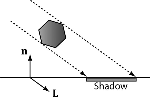
This is exactly the ith coordinate of s in Equation 11.1, so s = s′. To use the shadow matrix, we combine it with our world matrix. However, after the world transform, the geometry has not really been projected on to the shadow plane yet because the perspective divide has not occurred yet. A problem arises if sw = n·L < 0. because this makes the w-coordinate negative. Usually in the perspective projection process we copy the z-coordinate into the w-coordinate, and a negative w-coordinate would mean the point is not in the view volume and thus is clipped away (clipping is done in homogeneous space before the divide). This is a problem for planar shadows because we are now using the w-coordinate to implement shadows, in addition to the perspective divide. Figure 11.8 shows a valid situation where n·L < 0, but the shadow will not show up.
Figure 11.8. A situation where n·L < 0. To fix this, instead of using the light ray direction L, we should use the vector towards the infinitely far away light source
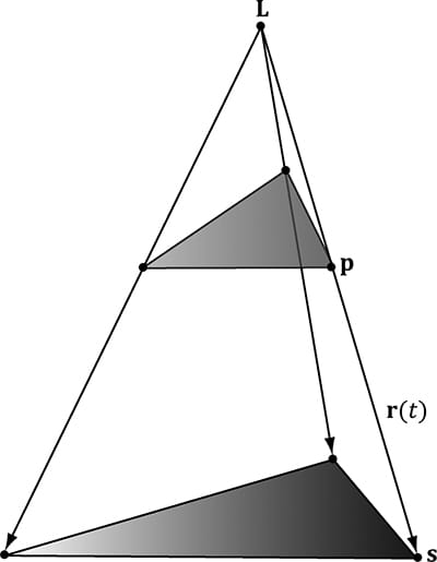
Figure 11.9. The shadow cast with respect to a point light source. 11.5.2 Point Light Shadows Figure 11.9 shows the shadow an object casts with respect to a point light source whose position is described by the point L. The light ray from a point light through any vertex p is given by r(t) = p + t(p − L). The intersection of the ray r(t) with the shadow plane (n, d) gives s. The set of intersection points found by shooting a ray through each of the object’s vertices with the plane defines the projected geometry of the shadow. For a vertex p, its shadow projection is given by
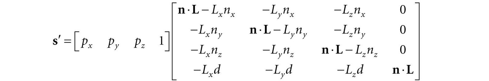
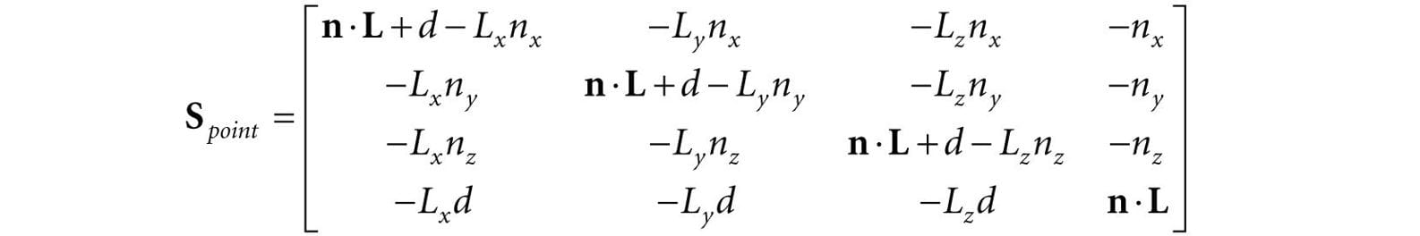
Equation 11.2 can also be written by a matrix equation:
To see how this matrix is equivalent to Equation 11.2, we just need to perform the multiplication the same way we did in the previous section. Note that the last column has no zeros and gives:
This is the negative of the denominator in Equation 11.2, but we can negate the denominator if we also negate the numerator.
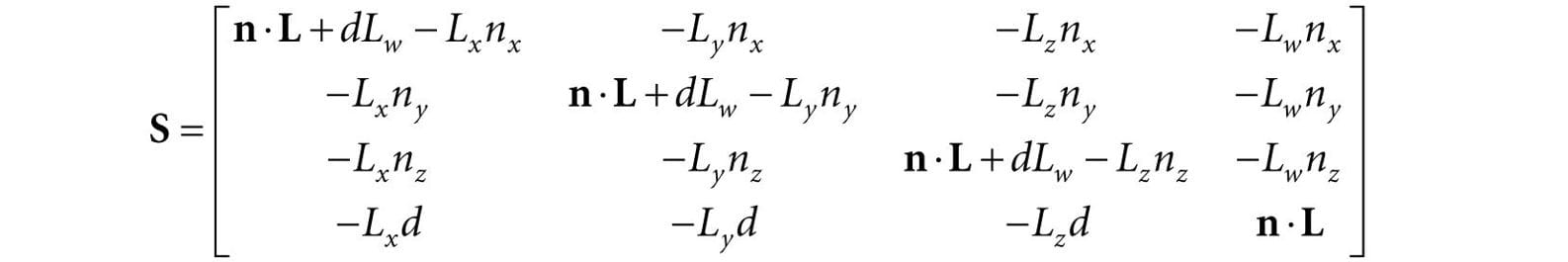
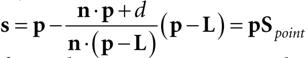
11.5.3 General Shadow Matrix Using homogeneous coordinates, it is possible to create a general shadow matrix that works for both point and directional lights. 1. If Lw = 0 then L describes the direction towards the infinitely far away light source (i.e., the opposite direction the parallel light rays travel). 2. If Lw = 1 then L describes the location of the point light. Then we represent the transformation from a vertex p to its projection s with the following shadow matrix:
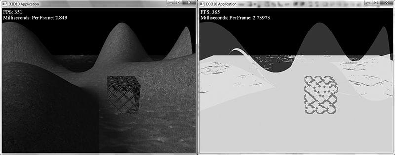
It is easy to see that S reduced to Sdir if Lw = 0 and S reduces to Spoint for Lw = 0. The DirectX math library provides the following function to build the shadow matrix given the plane we wish to project the shadow into and a vector describing a parallel light if w = 0 or a point light if w = 1: inline XMMATRIX XM_CALLCONV XMMatrixShadow( FXMVECTOR ShadowPlane, FXMVECTOR LightPosition); For further reading, both [Blinn96] and [Möller02] discuss planar shadows. 11.5.4 Using the Stencil Buffer to Prevent Double Blending When we flatten out the geometry of an object onto the plane to describe its shadow, it is possible (and in fact likely) that two or more of the flattened triangles will overlap. When we render the shadow with transparency (using blending), these areas that have overlapping triangles will get blended multiple times and thus appear darker. Figure 11.10 shows this.
Figure 11.10. Notice the darker “acne” areas of the shadow in the left image; these correspond to areas where parts of the flattened skull overlapped, thus causing a “double blend.” The image on the right shows the shadow rendered correctly, without double blending. We can solve this problem using the stencil buffer. 1. Assume the stencil buffer pixels where the shadow will be rendered have been cleared to 0. This is true in our mirror demo because we are only casting a shadow onto the ground plane, and we only modified the mirror stencil buffer pixels. 2. Set the stencil test to only accept pixels if the stencil buffer has an entry of 0. If the stencil test passes, then we increment the stencil buffer value to 1. The first time we render a shadow pixel, the stencil test will pass because the stencil buffer entry is 0. However, when we render this pixel, we also increment the corresponding stencil buffer entry to 1. Thus, if we attempt to overwrite to an area that has already been rendered to (marked in the stencil buffer with a value of 1), the stencil test will fail. This prevents drawing over the same pixel more than once, and thus prevents double blending. 11.5.5 Shadow Code We define a shadow material used to color the shadow that is just a 50% transparent black material: auto shadowMat = std::make_unique<Material>(); shadowMat->Name = "shadowMat"; shadowMat->MatCBIndex = 4; shadowMat->DiffuseSrvHeapIndex = 3; shadowMat->DiffuseAlbedo = XMFLOAT4(0.0f, 0.0f, 0.0f, 0.5f); shadowMat->FresnelR0 = XMFLOAT3(0.001f, 0.001f, 0.001f); shadowMat->Roughness = 0.0f; In order to prevent double blending we set up the following PSO with depth/stencil state: // We are going to draw shadows with transparency, so base it off // the transparency description. D3D12_DEPTH_STENCIL_DESC shadowDSS; shadowDSS.DepthEnable = true; shadowDSS.DepthWriteMask = D3D12_DEPTH_WRITE_MASK_ALL; shadowDSS.DepthFunc = D3D12_COMPARISON_FUNC_LESS; shadowDSS.StencilEnable = true; shadowDSS.StencilReadMask = 0xff; shadowDSS.StencilWriteMask = 0xff; shadowDSS.FrontFace.StencilFailOp = D3D12_STENCIL_OP_KEEP; shadowDSS.FrontFace.StencilDepthFailOp = D3D12_STENCIL_OP_KEEP; shadowDSS.FrontFace.StencilPassOp = D3D12_STENCIL_OP_INCR; shadowDSS.FrontFace.StencilFunc = D3D12_COMPARISON_FUNC_EQUAL; // We are not rendering backfacing polygons, so these settings do not // matter. shadowDSS.BackFace.StencilFailOp = D3D12_STENCIL_OP_KEEP; shadowDSS.BackFace.StencilDepthFailOp = D3D12_STENCIL_OP_KEEP; shadowDSS.BackFace.StencilPassOp = D3D12_STENCIL_OP_INCR; shadowDSS.BackFace.StencilFunc = D3D12_COMPARISON_FUNC_EQUAL; D3D12_GRAPHICS_PIPELINE_STATE_DESC shadowPsoDesc = transparentPsoDesc; shadowPsoDesc.DepthStencilState = shadowDSS; ThrowIfFailed(md3dDevice->CreateGraphicsPipelineState( &shadowPsoDesc, IID_PPV_ARGS(&mPSOs["shadow"]))); We then draw the skull shadow with the shadow PSO with a StencilRef value of 0: // Draw shadows mCommandList->OMSetStencilRef(0); mCommandList->SetPipelineState(mPSOs["shadow"].Get()); DrawRenderItems(mCommandList.Get(), mRitemLayer[(int)RenderLayer::Shadow]); where the skull shadow render-item’s world matrix is computed like so: // Update shadow world matrix. XMVECTOR shadowPlane = XMVectorSet(0.0f, 1.0f, 0.0f, 0.0f); // xz plane XMVECTOR toMainLight = -XMLoadFloat3(&mMainPassCB.Lights[0].Direction); XMMATRIX S = XMMatrixShadow(shadowPlane, toMainLight); XMMATRIX shadowOffsetY = XMMatrixTranslation(0.0f, 0.001f, 0.0f); XMStoreFloat4x4(&mShadowedSkullRitem->World, skullWorld * S * shadowOffsetY); Note that we offset the projected shadow mesh along the y-axis by a small amount to prevent z-fighting so the shadow mesh does not intersect the floor mesh, but lies slightly above it. If the meshes did intersect, then due to limited precision of the depth buffer, we would see flickering artifacts as the floor and shadow mesh pixels compete to be visible. 11.6 SUMMARY 1. The stencil buffer is an off-screen buffer we can use to block the rendering of certain pixel fragments to the back buffer. The stencil buffer is shared with the depth buffer and thus has the same resolution as the depth buffer. Valid depth/stencil buffer formats are DXGI_FORMAT_D32_FLOAT_S8X24_UINT and DXGI_FORMAT_D24_UNORM_S8_UINT. 2. The decision to block a particular pixel from being written is decided by the stencil test, which is given by the following: if( StencilRef & StencilReadMask Value & StencilReadMask ) accept pixel else reject pixel 3. where the 4. The depth/stencil state is part of a PSO description. Specifically, the depth/stencil state is configured by filling out the D3D12_GRAPHICS_PIPELINE_STATE_DESC::DepthStencilState field, where DepthStencilState is of type D3D12_DEPTH_STENCIL_DESC. 5. The stencil reference value is set with the ID3D12GraphicsCommandList::OMSetStencilRef method, which takes a single unsigned integer parameter specifying the stencil reference value. 11.7 EXERCISES 1. Prove that the general shadow matrix S reduced to Sdir if Lw = 0 and S reduces to Spoint for Lw = 1. 2. Prove that by doing the matrix multiplication for each component, as was done in §11.5.1 for directional lights. 3. Modify the “Mirror” demo to produce the “Left” image in Figure 11.1. 4. Modify the “Mirror” demo to produce the “Left” image in Figure 11.10. 5. Modify the “Mirror” demo in the following way. First draw a wall with the following depth settings: depthStencilDesc.DepthEnable = false; depthStencilDesc.DepthWriteMask = D3D12_DEPTH_WRITE_MASK_ALL; depthStencilDesc.DepthFunc = D3D12_COMPARISON_LESS;
depthStencilDesc.DepthEnable = true; depthStencilDesc.DepthWriteMask = D3D12_DEPTH_WRITE_MASK_ALL; depthStencilDesc.DepthFunc = D3D12_COMPARISON_LESS;
depthStencilDesc.DepthEnable = true; depthStencilDesc.DepthWriteMask = D3D12_DEPTH_WRITE_MASK_ALL; depthStencilDesc.DepthFunc = D3D12_COMPARISON_LESS;
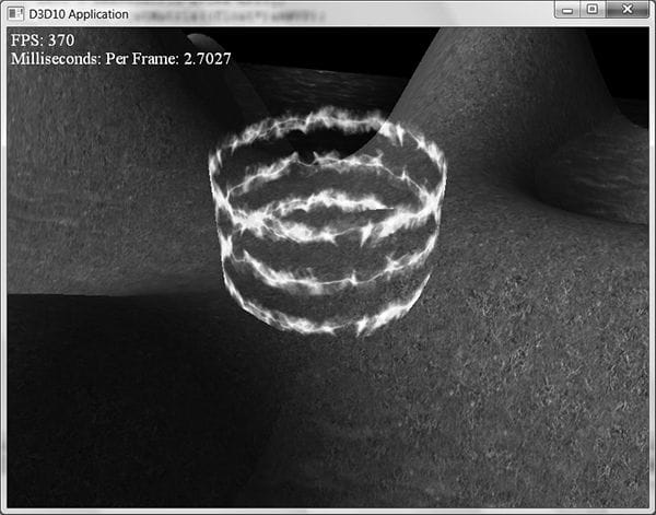
6. Modify the “Mirror” demo by not reversing the triangle winding order convention. Does the reflected teapot render correctly? 7. Modify the “Blend” demo from Chapter 10 to draw a cylinder (with no caps) at the center of the scene. Texture the cylinder with the 60 frame animated electric bolt animation found in this chapter’s directory using additive blending. Figure 11.11 shows an example of the output.
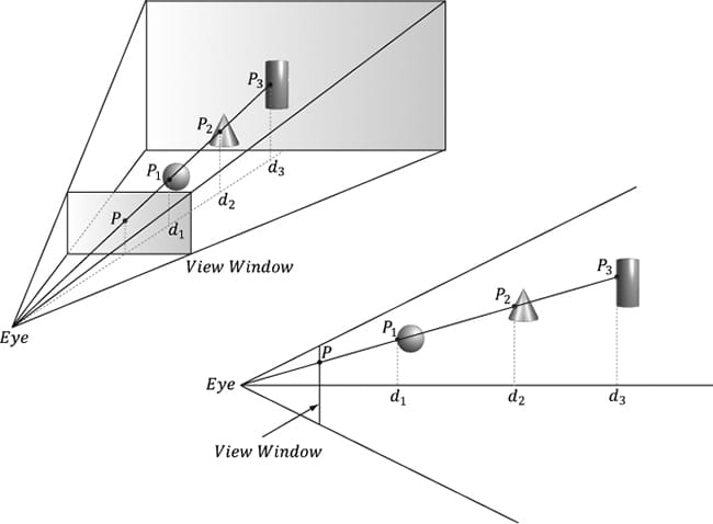
Figure 11.11. Sample screenshot of the solution to Exercise 7. 8. Depth complexity refers to the number of pixel fragments that compete, via the depth test, to be written to a particular entry in the back buffer. For example, a pixel we have drawn may be overwritten by a pixel that is closer to the camera (and this can happen several times before the closest pixel is actually figured out once the entire scene has been drawn). The pixel in Figure 11.12 has a depth complexity of 3 since three pixel fragments compete for the pixel.
Figure 11.12. Multiple pixel fragments competing to be rendering to a single pixel on the projection window. In this scene, the pixel P has a depth complexity of 3.
1. Associate a color ck for each level of depth complexity k. For example, blue for a depth complexity of one, green for a depth complexity of two, red for a depth complexity of three, and so on. (In very complex scenes where the depth complexity for a pixel could get very large, you probably do not want to associate a color for each level. Instead, you could associate a color for a range of disjoint levels. For example, pixels with depth complexity 1-5 are colored blue, pixels with depth complexity 6-10 are colored green, and so on.) 2. Set the stencil buffer operation to D3D12_STENCIL_OP_KEEP so that we do not modify it anymore. (We modify the stencil buffer with D3D12_STENCIL_OP_INCR when we are counting the depth complexity as the scene is rendered, but when writing the code to visualize the stencil buffer, we only need to read from the stencil buffer and we should not write to it.) 3. For each level of depth complexity k: 1. Set the stencil comparison function to D3D12_COMPARISON_EQUAL and set the stencil reference value to k. 2. draw a quad of color ck that covers the entire projection window. Note that this will only color the pixels that have a depth complexity of k because of the preceding set stencil comparison function and reference value.
Figure 11.13. Sample screenshot of the solution to Exercise 8.
struct PixelOut { float4 color : SV_Target; float depth : SV_Depth; }; PixelOut PS(VertexOut pin) { PixelOut pout; // … usual pixel work pout.Color = float4(litColor, alpha); // set pixel depth in normalized [0, 1] range pout.depth = pin.PosH.z - 0.05f; return pout; }
9. Another way to implement depth complexity visualization is to use additive blending. First clear the back buffer black and disable the depth test. Next, set the source and destination blend factors both to D3D12_BLEND_ONE, and the blend operation to D3D12_BLEND_OP_ADD so that the blending equation looks like C = Csrc + Cdst. Observe that with this formula, for each pixel, we are accumulating the colors of all the pixel fragments written to it. Now render all the objects in the scene with a pixel shader that outputs a low intensity color like (0.05, 0.05, 0.05). The more overdraw a pixel has, the more of these low intensity colors will be summed in, thus increasing the brightness of the pixel. If a pixel was overdrawn ten times, for example, then it will have a color intensity of (0.5, 0.5, 0.5). Thus by looking at the intensity of each pixel after rendering the scene, we obtain an idea of the scene depth complexity. Implement this version of depth complexity measurement using the “Blend” demo from Chapter 10 as a test scene. 10.Explain how you can count the number of pixels that pass the depth test. Explain how you can count the number of pixels that fail the depth test? 11.Modify the “Mirror” demo to reflect the floor into the mirror in addition to the skull. 12.Remove the vertical offset from the world matrix of the shadow render-item so that you can see z-fighting. All materials on the site are licensed Creative Commons Attribution-Sharealike 3.0 Unported CC BY-SA 3.0 & GNU Free Documentation License (GFDL) If you are the copyright holder of any material contained on our site and intend to remove it, please contact our site administrator for approval. © 2016-2026 All site design rights belong to S.Y.A. |