Arduino Sketches: Tools and Techniques for Programming Wizardry (2015)
Part IV. User Libraries and Shields
Chapter 26. Creating Your Own Library
This chapter discusses how to create your own library. You can find the code downloads for this chapter at http://www.wiley.com/go/arduinosketches on the Download Code tab. The code is in the Chapter 26 download and individually named according to the filenames noted throughout this chapter.
The Arduino project has had an immense success since its creation, and there are several reasons. The cost is, of course, an important criterion to any project. Continuous R & D has also helped, but one of the primary reasons today is simple: the openness of the project. The Arduino community is extremely active. Just look at the Arduino forums: Google+ groups or Arduino events organized in cities throughout the world. This is the community that drives the ongoing evolution of the platform, either by getting the tools to work with new electronic components and breakout boards, or finding and creating their own when nothing exists. In Chapter 25 you created your own shield, now you will create your own library.
Libraries
You can use libraries for several applications, but two main uses exist. One is to have specific routines such as temperature conversion, data processing, or hardware I/O. The second use is to allow the use of specific hardware, hiding away any long routines, and making hardware easy to use. This chapter looks at both of these kinds of libraries.
Library Basics
When you import a library, you import an .h file, the header file. This is a text file that describes what is in a C++ file (that ends with the .cpp extension). Header files are used in most C and C++ projects. They are not required for sketches but are required for libraries. They are a simple way of telling the compiler what to expect in the C++ file and how to use it. It is also an excellent way for developers to know what is contained in a library; everything is listed in just a few lines.
Simple Libraries
Function libraries are an easy entry into writing a library; they contain simple functions similar to ones you might write in your main sketch. Don't worry, you'll look at making some with advanced capabilities in the “Advanced Libraries” section. For now, these contain only simple functions, and their header file is straightforward.
You can demonstrate the use of a potential library with a function call. You can use an Arduino to calculate the answer to the Ultimate Question of Life, the Universe, and Everything. Luckily, Douglas Adams has already answered this question in The Hitchhiker's Guide to the Galaxy; a super-computer calculated this question for 7.5 million years before coming up with the answer: 42. Luckily, the Arduino is a lot faster to come up with the answer, and the function looks simple:
int theAnswer()
{
return 42;
}
Looks simple, doesn't it? The only difficulty is making this function usable as a library. It requires a few things to set up before it is useable. First, you must think of a name for the library, as well as the folder that will contain your files. The choice of the name is important because it will also be used for the name displayed on the Import Library menu item. Try to think of a name that clearly identifies the library you will create—either the component name, function, or application. Users of your library will depend on this. For this example, use theAnswerToEverything.
Create a folder with this name on your desktop or anywhere you have easy access to. Next, you need to create two files: the source file and the header file. The Arduino IDE cannot directly open or save C++ and .h files. These can be created with a standard text editor or with an IDE. Code::Blocks is a freeware IDE that works on several platforms, including Windows, Linux, and Mac OS. It is available from www.codeblocks.org/downloads/.
The header file is a file that contains a description of the functions that you will be writing. Its name is just as important as the name of the library and folder it lives within. For example, when you import the EEPROM library, you add this line:
#include <EEPROM.h>
This is the header file. Typically, it has the same name as the folder it is held in, but not always. For example, when importing the Wi-Fi library, you may see this:
#include <WiFi.h>
#include <WiFiServer.h>
#include <WiFiClient.h>
#include <WiFiUdp.h>
Several header files are located inside this folder, and if you use the Import Library functionality in the IDE, all header files are automatically imported. If named well, they clearly state what they do, so anyone using the library can know what the headers do and if they are needed. Imagine another sort of name:
#include <stuff.h>
This isn't clear, and users will have no idea what this library does. Remember to keep your library name precise and clear.
First, create a source file named theAnswerToEverything.cpp. The source file is written in C++ and has the extension .cpp. Add the following contents to the file and save it:
int theAnswer()
{
return 42;
}
There is just this one function; it takes no parameters and returns an int. The Arduino IDE still does not know about this function; it has to be declared. This is the role of the header file. Create a new file named theAnswerToEverything.h and add the following:
int theAnswer();
Did you see the difference? It is the same structure, only instead of having source code within brackets, the line is immediately ended with a semicolon. This is the declaration. It tells the compiler that this function exists, that it returns an int, and that it takes no parameters. If called, the compiler will know that it can find the source code within the .cpp file.
There is also one other line that is required and that should be placed at the very beginning of the file:
#include "Arduino.h"
This imports the Arduino header file, giving you access to Arduino constants and types. It is automatically included for your sketches, but for libraries, you must manually add this include statement.
All that is left to do is to import your new library. From the Arduino IDE, go to Sketch ![]() Import Library
Import Library ![]() Add Library, as shown in Figure 26.1.
Add Library, as shown in Figure 26.1.
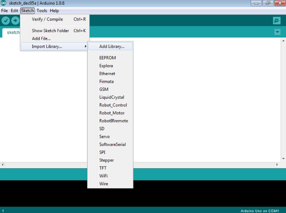
Figure 26.1 Import a library.
Select the folder that contains your library, and import it. If everything goes well, the Arduino IDE should tell you that the import has finished. You can see your library by navigating back to Sketch ![]() Import Library where you see a new library listed, as shown inFigure 26.2.
Import Library where you see a new library listed, as shown inFigure 26.2.
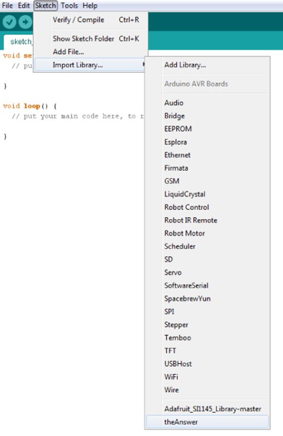
Figure 26.2 A new library has been added.
Now that the library has been imported, it is time to test it. Create a new sketch, and add your library by going to the menu Sketches ![]() Add Library
Add Library ![]() theAnswerToEverything. This should add the following line:
theAnswerToEverything. This should add the following line:
#include <theAnswerToEverything.h>
With that in place, it is now time to use the function you created previously. Add the following lines to setup(), calling the library's function:
void setup() {
// put your setup code here, to run once:
Serial.begin(9600);
Serial.print("The answer is ");
Serial.println(theAnswer());
}
Compile it to make sure that everything works well. Then upload it to your Arduino, and have a look at the serial output. Congratulations! You have just created your first library.
Advanced Libraries
The previous example used only simple functions, but Arduino libraries are capable of much, much more. You have seen how to initialize external hardware with the Arduino, usually by specifying some hardware pins. For example, when using the Servo library, the user must specify which pin is connected to the servo. Afterward, functions are available to control the servo, but the user does not have to tell the driver which pin to use. The reason is simple: the driver has stored that data in memory, so the user does not need to specify it every time. How? C++ classes.
C++ development is oriented around objects. What is an object? It can be many things, but mainly, it is a collection of variables and functions, all rolled into a C++ class. A class provides blueprints; it does not define any data, but defines data types. An object is then created by using the class blueprint.
Imagine a traffic light. It has three lights: red, yellow, and green. Physically, three lights are connected to a microcontroller, and the microcontroller issues instructions to each output pin; turn on the red light, and turn off the yellow light. The traffic light is physically an object. If you make a second traffic light, it is a copy of the first; it does exactly the same thing, has the same hardware, and will be used for the same applications as the first traffic light, but it operates independently of the first. This is similar to the concept of a software object. In software, an object is a structure in memory that contains the data and functionality all wrapped up in one package. In this case, imagine an object called trafficLight. It will have several functions to allow it to work and several variables to help it keep track of its state. If you create a traffic light and connect it to an Arduino, you could create a trafficLight object. Connect a second one, and you could create a second trafficLight object, and so on.
An object is defined by a C++ class. A class is a structure of code that contains functions, variables, and a constructor. Here's an example.
A traffic light requires three pins to work: one to activate the red light, one for the yellow, and one for the green. Under normal conditions, only one light should ever be on at the same time. This is easy to accomplish, but it requires you to do two things; turn off the previous light, and turn on the new light. This is easy enough with one traffic light, but with multiple lights, it would become increasingly difficult to manage all the pins and variables to keep track of their states. To make things easier, you could make an object.
To create an object, you need several things. First, you need a way to configure the object; telling it which pins to use. Then, it requires at least three functions for manipulating the lights. Naming them after the color they control can make it more intuitive: red(),amber(), and green(). When creating this library, start with the header file, and “describe” the object before building the different parts. This is what the object in the header file TrafficLight.h might look like:
1 class TrafficLight
2 {
3 private:
4 int _redpin, _yellowpin, _greenpin;
5
6 public:
7 TrafficLight(int redpin, int yellowpin, int greenpin);
8 void begin();
9 void red();
10 void yellow();
11 void green();
12 };
First, the class TrafficLight is defined. This is the object that will be created in your sketch. Next, it has two parts: one called public and one called private. The public section is where you will place functions and variables that will be visible to the sketch. This includes functions for controlling the state of the lights that you (or someone else using your library) will call in the main sketch. The private section contains functions and variables that are not visible to the sketch, only to the object. You can see how this works in a few paragraphs.
On line 7, there is an interesting function. It is called TrafficLight, the same name as the class. It takes three parameters, does not return any data, and isn't even declared as void. This is known as the constructor, which is a function that is automatically called when the object is created and is even called before setup(). The constructor is vitally important because it initializes any variables that need to be set up before the sketch has a chance to execute any functions. Typically, constructors take parameters, in this case the pins that will be used.
There is another important requirement for header files. When a header file is imported, the file is parsed, and the compiler knows what functions are available. If the same file is imported again, it can lead to confusing results, and compilers will complain. To make sure this does not happen, it is common to wrap up the header file in a construct:
#ifndef TrafficLight_h
#define TrafficLight_h
// Include statements and code go here
#endif
This construct prevents problems if somebody includes the library twice.
In the sketch, the TrafficLight object would be created like this:
const int redNorthPin = 2;
const int yellowNorthPin = 3;
const int greenNorthPin = 4;
TrafficLight northLight = TrafficLight(redNorthPin, yellowNorthPin,
greenNorthPin);
When this object is created, the constructor is called with the three variables. Now it is time to write the constructor. This function would be included in TrafficLight.cpp:
TrafficLight::TrafficLight(int redpin, int yellowpin, int greenpin)
{
_redpin = redpin;
_yellowpin = yellowpin;
_greenpin = greenpin;
}
The function is extremely simple, but it does differ from functions that have been previously written in this book. First, the function name: TrafficLight::TrafficLight. The first part, TrafficLight::, is the name of the class that the function will belong to. The second part is the function name. Because this is a constructor, it must have the exact same name as the class. It takes three int variables. Inside the function, the parameters it was given are stored in three variables: _red, _yellow, and _green. Where do they come from? They were defined in the header file on line 4. Because they are in the private section, they cannot be called from the sketch but are used inside this particular class object. Let the user have access to the required functions, and keep the rest hidden away. Imagine that you have two traffic lights, a northbound light and a southbound light. They are created like this:
TrafficLight northLight = TrafficLight(1, 2, 3);
TrafficLight southLight = TrafficLight(9, 8, 7);
Both have been created with different variables. When these objects were created, each called the constructor independently. Their private variables are also different: northLight's _red variable contains the value 1, but southLight's _red contains the value 9. You can create many objects with the same functionality but with different variables. This makes it possible to turn the northbound light red, stopping all traffic, while turning the southbound light green, allowing traffic to go straight, or to turn at a rather difficult junction, without any other traffic.
On line 8 of the header file, there is another function, begin(). You have seen functions with the same name throughout this book, which are used when a device is ready to be used. The constructor set up only the variables; it did not set any outputs, or even declare any pins as output. Typically, this is done in a begin() function. The sketch might need those pins for something else before using a traffic light, so it is often good practice to wait until the begin() function is called. A begin() function might look like this:
Boolean TrafficLight::begin(void)
{
// Set pins as outputs
pinMode(_redpin, OUTPUT);
pinMode(_yellowpin, OUTPUT);
pinMode(_greenpin, OUTPUT);
// Set Yellow and Green off
digitalWrite(_yellowpin, LOW);
digitalWrite(_greenpin, LOW);
// Set Red on
digitalWrite(_redpin, HIGH);
return true;
}
The begin() function sets the traffic light pins as outputs, and sets the yellow and green lights to off. As a security, these traffic lights will start with the red light on, halting traffic, adding a level of security before deciding which direction should be green. Next, you need to create functions to turn on individual lights. When activating the green light, both the red and yellow light are to be turned off. The greenLight() function might look like this:
void TrafficLight::greenLight(void)
{
// Set Red and Yellow off
digitalWrite(_redpin, LOW);
digitalWrite(_yellowpin, LOW);
// Set Green on
digitalWrite(_greenpin, HIGH);
}
Adding Comments
Comments are a critical part of any code and are unfortunately often omitted. They serve several purposes and are particularly useful in libraries.
Most comments are used inside code to explain the function of a portion of code. Of course you know what the code does; you have spent an hour writing it, and even more debugging it, and it has become perfect: elegant and functional. Would co-workers understand what you have done? They might have come up with another way and may be confused by your code if it isn't explained a little, no matter how elegant it is. Also, would you read your code 1 year from now? You might have done dozens of different projects, and your coding style might have changed since this project. Be nice to people; don't hesitate to write a comment if you think it could be helpful.
Ironically, one of the problems with comments is when there are too many comments, or even useless comments. If a variable called inputPin is declared as an int, there is no point writing a comment to say that it is an input pin and that it is declared as an int.
Comments are not just about functionality but also about the project. Someone reading the traffic light header file may understand what the library does, but there are several types of traffic lights. Most of the time, two traffic lights are identical; if the northbound light is green, then the southbound light is too, allowing traffic to flow in both directions. This isn't the case for this library; the advantage is that you can control both lights independently, but the disadvantage is that it generates more work. Tell the user that!
/***************************************************
This library is used to control a single traffic light,
it does not allow you to create pairs, instead, you have
full control over the way you want the traffic light to
behave.
It requires three pins per traffic light
Written by an Arduino Sketches reader
BSD license, all text above must be included in any redistribution
***************************************************/
class TrafficLight
{
private:
uint8_t _redpin, _amberpin, _greenpin;
public:
TrafficLight(uint8_t redpin, uint8_t amberpin, uint8_t greenpin);
void begin();
void red();
void amber();
void green();
};
It is now clear what the library is used for. Also, you get to add your name to a project to let people know who did this amazing library, which allows you to set a license. All the code available in this book has the BSD license—either code written by myself or by other parties. The BSD license makes the code free to use, but without any guarantee. It is free to redistribute, but the original license must remain. It allows code to be used in part or in whole in any software project, free or commercial. Remember that the Arduino project is open source; be nice and give back to the community when possible.
Adding Examples
Now that you have read through this example and added functions to turn on the different lights, it is time to move on. Before distributing your library, your users need to know how the library works. You can spend time writing documentation, but the easiest way to show people how a library works is to create an example program. From there, they can upload the example to an Arduino, modify the code to see how it works, and then copy/paste parts of the example into their own projects.
An example program is simply a sketch that uses your library. Again, make sure to comment your code to make it readable, and explain what is being done. Don't use a variable that hasn't been explained.
To add an example, first, write a sketch that uses the library. Next, go to the folder that you are creating for your library. Inside this folder, create a folder, “examples”. This is where the examples will be placed. Inside that folder, create another folder, the name of the example you want to create. Some libraries might require several examples. (Remember, the Ethernet library in Chapter 9 has multiple examples for servers and clients.) Now, paste your sketch inside this folder, keeping the same name as the folder but with the extension .ino (for Arduino sketch). Alternately, you can use the Arduino IDE to create the files and save them to disk directly. When the folder is imported, the Arduino IDE automatically adds any examples it finds into the Examples menu. For example, Figure 26.3shows my TrafficLight library folder with two example sketches.
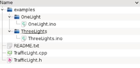
Figure 26.3 Traffic lights folder layout
Read Me
Most projects contain a README file—a text file that contains information about files in a folder. Historically, they were used to describe the contents of a folder, and were sometimes called README.1ST to inform the user that the contents should be read first. The README file should contain information about the project, the functionality that the library adds, what the user needs to make it work, and the examples included. This gives the user a good idea about what your library does without having to look at the source code.
Coding Style
To make it easier to both use and to distribute libraries, certain coding styles should be followed. These general rules make everything simpler and to make sure that everyone has a great time when programming Arduino. You can find the official API style guide here at http://arduino.cc/en/Reference/APIStyleGuide.
Use CamelCase
Sooner or later, you will need to write a function that is two or three words long. To put several words into a single compound phrase, there are several techniques possible. Programming languages are full of examples; using underscores results in functions likethis_function(), and some languages even went as far as to put the first word in uppercase and the second in lowercase, but THESEfunctions() isn't easy to read.
The Arduino style uses CamelCase: each word starts with a capital with the exception of the first letter. Functions are easier to read that way; functions such as readFile() or openImage() are immediately clear and remain perfectly readable. CamelCase is even used for multiple everyday objects; the first known use of CamelCase is in a 1950s technology called CinemaScope. Some readers might be reading this book on an eReader, another example of CamelCase.
CamelCase does have one disadvantage; it can be difficult to read functions that contain several uppercase letters: ReadID()for example. Of course, the function can read an ID, but functions such as GetTCPIPSocketID() become complicated. Should you writeGetTCPIPSocketID() or GetTcpIpSocketId()? Generally, you should avoid abbreviations, but when they are inevitable, it is often better to write them as capitals.
Use English Words
Don't shorten words for your functions. If you can't explain it in three words, look for another way. Always use complete words: deleteFile() is always clearer than delFile(), and oFile() doesn't mean anything, where openFile() does. Again, it is better to avoid abbreviations because only some abbreviations are clear to most people. You have probably heard of HTML, and writing “Hyper Text Markup Language” is going to make some ridiculously long function names. You can find a perfect example in the Arduino libraries; they don't talk about PWM, they called the function analogWrite().
Don't Use External Libraries
If you are writing a library, make sure that it uses only the Arduino standard libraries, or if absolutely necessary, board-specific libraries. If you have a great idea for a function, but one that can run only on an Arduino Esplora, then you can use the Esplora libraries. However, if it can be used on any Arduino, it would be a shame to limit it to one device. Similarly, don't rely on third-party external libraries; you are creating an external library, and users might not want to use your library if it depends on another one. Importing several libraries makes the code bigger.
Use Standard Names
Most hardware-related drivers use a begin() function in their code. Don't try to find synonyms; keep the same names as other functions. For example, if obtaining data, always use read: readInput()or readStatus(). When outputting, use write: writeData().
Distributing Your Library
When the coding is complete and the testing has been done, it is time to distribute your library. You can create a Zip file of your library and post it on your homepage (or the page you use to sell your hardware). This makes the library available to buyers (or visitors to your site) but does not increase visibility.
To make your library as visible as possible, consider putting it on one of the many sites designed specifically for source code, such as Sourceforge, GitHub, or Google Code. There are dozens of sites available for free, so long as your project is open source. This also automatically adds your library to search engines and allows users to help add new features, be alerted to updates, and make comments and requests.
Closed Source Libraries
A closed source library is one where you distribute binary code, and users are not allowed to see the source code. They cannot see the work you have done and therefore cannot modify the library. This also adds the possibility of requesting payment for use of your library, but it goes against everything the Arduino project is trying to do and is also technically extremely difficult to achieve.
Compilers and linkers take source code and transform it into machine code, code that can be executed on a microcontroller or processor. This is generally the format in which closed source libraries are distributed. The problem is that binary files are created for one specific processor and cannot be used on another. A program compiled for an AVR cannot be run on an ARM-based device such as the Arduino Due or an Intel-based device such as the Galileo. It has to be recompiled. Even worse, not all AVRs are the same; there are differences in models that make binary code imports impossible. In short, releasing a binary-only library makes that library usable on a single Arduino model.
Example Library
In Chapter 25, you created a shield for Arduino based on the PCF8574AP. Now it is time to write a library to use this device. If you haven't created your shield yet, or if you haven't received it, don't worry; you can still use the breadboard version presented in that chapter, which works in exactly the same way.
The Library
The I2C expander shield contains two PCF8574AP chips, both of which have configurable addresses. Therefore, you must select two addresses to use for your devices. You can choose which device will be the first selected—either chip 0 or chip 1 depending on the application. This will be handled in the constructor. The two addresses must be stored inside the class for the rest of the application to work. To do this, they will be saved as two 8-bit variables called _chip0Address and _chip1Address. Part of the job of the expander shield is to provide extra outputs: two banks of 8 pins. To make this easier to the user, the library should be designed to allow three different write operations: bit by bit, 8-bit writes, or 16-bit writes. The Arduino naming convention states that these operations should be called write, and the functions will be called writeBit(), writeByte(), and writeWord(). To write a bit, two values are required: the bit to write and its position. The bit will be a boolean, and the position will be an 8-bit value. To write a byte, again, two values are required: the byte to write and which device to use. The byte will be coded as a byte (naturally), and the device will be a Bool: 0 for device 0 and 1 for device 1. To write a 16-bit word, only one parameter is required, the word itself. All three functions should return a boolean: true if the operation succeeded and false otherwise.
The other part of the expander's job is to read data. Three functions need to be created to read data. The Arduino naming convention states that they should be called read: readBit(), readByte(), and readWord(). The readBit() function should require one parameter, the bit to read, and output a boolean. The readByte() function requires one parameter, the chip ID, as a boolean, and returns a byte. The readWord() function does not require any parameters and returns a word.
Since these devices are I2C devices, they will also require the Wire library.
There is one thing that should be taken into account. The user might want to write a bit of data to one of the chips, but how do you do that without affecting the other bits? Well, as far as the chip is concerned, you can't. You can write only 8 bits of data at a time, the entire output of the chip. To achieve this, two more variables will be needed; _chip0Output and _chip1Output will both contain 8-bits of data, the data that will be sent to the chip. The user does not need to worry about how a bit of data is sent, or even be aware that the library cannot send a single bit, which is one of the reasons why libraries are so powerful. The library takes care of the details, letting the user concentrate on the sketch.
Finally, a begin() function will be written. This function will initialize the chip to a power-on state and will be called when the user is ready.
By simply thinking about what the user would need the shield to do, you'll have a good idea of what the header file should contain. It will look something like this (filename: PCF8574AP.h):
#include "Arduino.h"
class PCF8574AP
{
private:
int _chip0Address;
int _chip1Address;
int_chip0Output;
int _chip1Output;
public:
PCF8574AP(int chip1, int chip2);
void begin();
bool writeBit(bool bit, int pos);
bool writeByte(int data, bool chipSelect);
bool writeWord(int data);
bool readBit(int pos);
int readByte(bool chipSelect);
int readWord();
};
Now that the structure is created, it is time to work on the C++ file, called PCF8754AP.cpp. First, add references to the libraries it depends on—Arduino.h and Wire.h—as well as the library header, followed by the constructor:
#include "Arduino.h"
#include "Wire.h"
#include "PCF8574AP.h"
PCF8574AP::PCF8574AP(uint8_t chip0, uint8_t chip1)
{
_chip0Address = chip0;
_chip1Address = chip1;
}
And that's it. All that needs to be done is to copy the values sent as parameters into private variables. Configuration of the chip is done in begin() and will look like this:
void PCF8574AP::begin()
{
Wire.begin();
// Set all pins of chip 0 to HIGH
_chip0Output = 0xFF;
Wire.beginTransmission(_chip0Address);
Wire.write(_chip0Output);
Wire.endTransmission();
// Do the same for chip 1
_chip1Output = 0xFF;
Wire.beginTransmission(_chip1Address);
Wire.write(_chip1Output);
Wire.endTransmission();
}
The function begins by calling Wire.begin(). Why does it do that? Although the device requires the Wire library for communication, the user doesn't need to know exactly how the shield is connected. It's up to this function to initialize the I2C library and start communication with the chips. Next, the function then sets both output variables to 0xFF (or, in binary, 1111 1111). It then proceeds to write that value to each of the two chips. When the chips first power on, this is their default state. So why does this function do that, if this is what is expected? There is no guarantee that the device was powered on; it might just have been reset, or the device is in an unstable state. This makes sure that the device is in a known configuration before continuing.
Now to read data. The easiest function to accomplish is readByte(). It simply reads the 8 bits of the chip and returns that data.
uint8_t PCF8574AP::readByte(bool chipSelect)
{
byte _data = 0;
if(chipSelect == 1)
Wire.requestFrom(_chip1Address, 1);
else
Wire.requestFrom(_chip0Address, 1);
if(Wire.available())
{
_data = Wire.read();
}
return(_data);
}
This function requests 1 byte of data from either chip, depending on the value of chipSelect. If data is present in the I2C buffer, that data is copied into the local variable _data and then returned. If no data is available, the function returns zero.
Reading words is just like reading bytes, only 2 bytes are read. This function obtains a byte of data from both chips, merges them into a word, and then returns that data. This is accomplished with the following:
uint16_t PCF8574AP::readWord(void)
{
byte _data0 = 0;
byte _data1 = 0;
Wire.requestFrom(_chip0Address, 1);
if(Wire.available())
{
_data0 = Wire.read();
}
Wire.requestFrom(_chip1Address, 1);
if(Wire.available())
{
_data1 = Wire.read();
}
return(word(_data1, _data0));
}
Things become slightly more complex when reading a specific bit, requiring bitwise operations:
bool PCF8574AP::readBit(uint8_t pos)
{
byte _data = 0;
// Is the bit requested out of range?
if (pos > 15)
return 0;
if (pos < 8)
Wire.requestFrom(_chip0Address, 1);
else
{
Wire.requestFrom(_chip1Address, 1);
pos -= 8;
}
if(Wire.available())
{
_data = Wire.read();
}
return(bitRead(_data, pos));
}
The function reads in data from one of the chips with Wire.requestFrom(), depending on the bit position. If the requested bit is between 0 and 7, the request is sent to chip 0; otherwise it is sent to chip 1. Then, the Arduino function bitRead() is called, extracting the bit that was requested and returning it as a boolean value.
All the read functions have been completed, but it isn't over yet. The write functions need to be written. Writing a byte is straightforward:
bool PCF8574AP::writeByte(uint8_t data, bool chipSelect)
{
if (chipSelect == 0)
{
Wire.beginTransmission(_chip0Address);
_chip0Output = data;
Wire.write(_chip0Output);
}
else if (chipSelect == 1)
{
Wire.beginTransmission(_chip1Address);
_chip1Output = data;
Wire.write(_chip1Output);
}
else
{
return false;
}
Wire.endTransmission();
return true;
}
As with readByte(), writeByte() selects only one chip. If chipSelect is 0, an I2C transmission begins at chip 0. data is copied to _chip0Output, and its contents are sent to the device. If chip 1 is selected, the same operation occurs, but for chip 1. Finally, the data is sent, and the function returns true.
Writing a word is similar:
bool PCF8574AP::writeWord(uint16_t data)
{
Wire.beginTransmission(_chip0Address);
_chip0Output = ((uint8_t) ((data) & 0xff));
Wire.write(_chip0Output);
Wire.endTransmission();
delay(5);
Wire.beginTransmission(_chip1Address);
_chip1Output = ((uint8_t) ((data) >> 8));
Wire.write(_chip1Output);
Wire.endTransmission();
return true;
}
By now you should be accustomed to using both chips. The logic behind this is that both variables are updated, and both chips are updated with those variables. The trick comes in separating a word into 2 bytes; this is done with masks and shifts. The first conversion transforms a word into a byte, by omitting the first 8 bits using a mask. The second conversion does the same; only it shifts the first 8 bits to the right, essentially pushing the first 8 bits to the place of the second 8 bits, and then masking.
The last function that you need is writing individual bits:
bool PCF8574AP::writeBit(bool bit, uint8_t pos)
{
// Is the bit requested out of range?
if (pos > 15)
return false;
if (pos < 8)
{
//Chip 0
if (bit == true)
{
bitSet(_chip0Output, pos);
}
else
{
bitClear(_chip0Output, pos);
}
Wire.beginTransmission(_chip0Address);
Wire.write(_chip0Output);
Wire.endTransmission();
}
else
{
//Chip 1
if (bit == true)
{
bitSet(_chip1Output, pos - 8);
}
else
{
bitClear(_chip1Output, pos - 8);
}
Wire.beginTransmission(_chip1Address);
Wire.write(_chip1Output);
Wire.endTransmission();
}
return true;
}
Because the PCF8574AP can't actually read what it is outputting, when the user wants to modify a single bit, the function needs to know what the data is on the bus and then modify it. This is why it was necessary to save the output as a variable. This is the benefit of using a library, hiding a detail that end users don't need to know. Users can just see that they can modify a bit with a single instruction.
Examples
It doesn't matter how clear function names are; libraries are always better with examples. Example sketches also serve another purpose—to test the hardware. One of the best ways to test if the hardware is correctly set up is to open up an example and see it run. Even if the shield it drives is basic, users will still use example sketches as a basis for their own. Put simply: Example sketches need to clearly demonstrate the functionality of the library.
This library has two examples: one for writing outputs and the other for reading. Of course, the shield can do both at the same time, so comments need to be put in place to tell the user that. Also, critically important, the PCF8574AP can read inputs correctly only if the output is set to high; this needs to be clearly explained in a comment.
First, for the example to write outputs, you must think about what the user needs. Of course, he needs to understand the library. He will also need to set up an example. LCD screen examples are easy to set up; if you are using an LCD library, you probably already have the LCD screen. This case is different. Nothing on this particular shield is visible to the user; there are no LEDs, no LCD screens, nothing that can tell the user what is going on. To see what the shield can do, a user will have to add his own components. What should you use? Nothing too fancy. An awesome example would be to use an 8x8 LED matrix, but not everyone will have that. Don't use specific hardware in examples; use tools that are readily available. The cheapest, most readily available, and most robust component available to makers is the trusty LED; almost everyone has a few LEDs on their desk with the corresponding resistors. They might not have 16, so this example uses only one output, with 8 LEDs.
#include <Wire.h>
#include <PCF8574AP.h>
// Define the addresses of both chips on the expander board
#define EXPANDER_CHIP0 B0111000
#define EXPANDER_CHIP1 B0111001
// You must provide two I2C addresses, one for each chip on the shield
PCF8574AP expanderShield = PCF8574AP(EXPANDER_CHIP0, EXPANDER_CHIP1);
byte output;
void setup()
{
Serial.begin(9600);
expanderShield.begin(); // Start the expander shield, set all outputs
to 1
}
void loop()
{
// Write a 16-bit word to the expander shield, all ones
expanderShield.writeWord(0xFFFF);
delay(1000);
// Time to begin the light show
// Make the lights go towards the center by writing bytes
expanderShield.writeByte(B01111110, 0);
delay(1000);
expanderShield.writeByte(B00111100, 0);
delay(1000);
expanderShield.writeByte(B00011000, 0);
delay(1000);
expanderShield.writeByte(B00000000, 0);
delay(1000);
// Now make the lights go towards the edges by writing individual bits
// Bits can be set by writing a 1 or a 0 to a specific location: bits
0 to 15
expanderShield.writeBit(1, 0); // Write a logical 1 to bit 0 of the
expander shield
expanderShield.writeBit(1, 7); // Write a logical 1 to bit 7 of the
expander shield
delay(1000);
expanderShield.writeBit(1, 1);
expanderShield.writeBit(1, 6);
delay(1000);
expanderShield.writeBit(1, 2);
expanderShield.writeBit(1, 5);
delay(1000);
expanderShield.writeBit(1, 3);
expanderShield.writeBit(1, 4);
delay(1000);
// turn off all the lights
expanderShield.writeByte(0, 0);
delay(1000);
// Create a light display by shifting a bit from one side to the
other, increasing speed
for(int i = 0; i < 20; i++)
{
output = 1;
for(int j = 0; j < 8; j++)
{
// Write a byte to device 0 (the first I2C extender)
expanderShield.writeByte(output, 0);
delay(600 - (i * 30));
output = output << 1;
}
}
}
This example shows the user how to use the PCF8574AP I/O expander shield, and the very first thing it does is to include that library. To be able to use that library, the user must provide two pieces of information: the address for each component. To make this clear, the addresses are included as define statements on lines 5 and 6.
On line 9, the PCF8574AP object is created, called expanderShield. By using the defined addresses, the code becomes more readable, and the user understands what is required to get started. On line 13, the setup() function is declared, as with any sketch. Inside, the serial connection is configured and expanderShield is initialized with a begin() function.
The loop() function is declared on line 20, and this is where the example code will be placed. To show how the library can write words (or 16-bit numbers), the example uses the writeWord() function. This sets all the outputs to HIGH, turning the LEDs off.
Next, the user is presented with an example on how to use writeByte(). A series of four commands are run, each time setting more and more outputs to 0. The effect of this is to turn on the LEDs from the edge towards the center.
The next series of instructions demonstrates how to write individual bits using the writeBit() function. Once again, a visual effect is created, this time turning the LEDs off from the edge towards the center.
Finally, to make the example even more visually appealing, a final phase is used. By using two for loops and using one value for the output and another value for the delay between operations, the result is a racing light going from one side of the LEDs to the other, going ever faster and faster.
Multiple comments have been placed in the file to explain to the user what the sketch is doing. So long as LEDs are connected to the board (cathodes connected to the pins) the user will be presented with a nice light show.
README
Every project should have a README file, a simple text file that describes the project. When you look at a project on GitHub, the text you see on the project page comes directly from the README file in the project. Here is mine:
/***********************************************
ArduinoSketches Expander Shield Driver
This library is used to control the two PCF8754APs
present on the expander shield. They can perform both
reads and writes, but to perform a read, the output
on that pin must be high.
This library accesses those devices through bit-wise,
byte-wise or word-wise reads and writes.
Written by James A. Langbridge, enhanced by a reader of
Arduino Sketches.
Released under BSD license
To run the examples in this library, you will require
at least 8 LED lights, and corresponding resistors
(for red LEDs, use 150 ohm resistors). The anode should
be connected to the resistor and power supply, and the
cathode should be connected to the input/output of the
shield.
***********************************************/
The first line tells the user what this library is for: the Arduino Sketches expander shield. It contains a little more detail on the project, what it does, how it achieves that, who originally wrote it, and the license the project is distributed under. I wrote the original library, but you will continue the project. This library is distributed under the BSD library; use it in any way you see fit.
Secondly, the file also includes the list of components required to run the examples, if required. For this example, the user requires 8 LEDs, and the corresponding resistors.
Finishing Touches
As usual, the source code here is functional but could do with a little bit of tweaking. Remember those write functions that tell if the information was written correctly? They all return true for the time being, but you can enhance that by looking at the amount of bytes written to the I2C bus. Use that data to give a more accurate response.
One thing is missing from this library: to perform a read, the user must first make the output high. What would happen if that weren't done? The reading would not be accurate. You could add this to the read functions; because the outputs are known through a global variable, make sure that the output is high before reading.
You have your shield, and you have your library, hopefully with your name on both. Make this your project, and be creative with the applications you come up with. Don't forget to tell me all about your projects!
Summary
In this chapter you have seen how to create your own library, and how to make it easy to use by other users, by creating examples and other files. You have seen the importance of writing clear comments, how users will read your library, as well as the importance of naming your functions. Now you have a working library, ready to use with your own shield. All that is left to do is to imagine new applications!
All materials on the site are licensed Creative Commons Attribution-Sharealike 3.0 Unported CC BY-SA 3.0 & GNU Free Documentation License (GFDL)
If you are the copyright holder of any material contained on our site and intend to remove it, please contact our site administrator for approval.
© 2016-2026 All site design rights belong to S.Y.A.