Make: More Electronics (2014)
Preface
This book picks up where my previous introductory guide, Make: Electronics, left off. Here you will find topics that I did not explore in detail before, and other topics that were not covered at all because I lacked sufficient space. You will also find that I go a little bit further into technicalities, to enable a deeper understanding of the concepts. At the same time, I have tried to make “Learning by Discovery” as much fun as possible.
A few of the ideas here have been discussed previously in Make magazine, in very different forms. I always enjoy writing my regular column for Make, but the magazine format imposes strict limits on the wordage and the number of illustrations. I can provide much more comprehensive coverage in this book.
I have chosen not to deal with microcontrollers in much depth, because explaining their setup and programming language(s) in sufficient detail would require too much space. Other books already explain the various microcontroller chip families. I will suggest ways in which you can rebuild or simplify the projects here by using a microcontroller, but I will leave you to pursue this further on your own.
What You Need
Prior knowledge
You need a basic understanding of the topics that I covered in the previous book. These include voltage, current, resistance, and Ohm’s law; capacitors, switches, transistors, and timers; soldering and breadboarding; and a beginner’s knowledge of logic gates. Of course, you can also learn these topics from other introductory guides. Generally I assume that you have read Make: Electronics or a similar book, and you have a general memory of it, although you may have forgotten some specifics. Therefore I will include a few quick reminders without repeating the general principles to any significant extent.
Tools
I’m assuming you already own the following equipment, all of which was described in Make: Electronics:
§ Multimeter
§ 24-gauge multicolored hookup wire (25 feet of each color, in at least four colors)
§ Wire strippers
§ Pliers
§ Soldering iron and solder
§ Breadboard (the preferred type is described in the next section of the book.)
§ 9V battery, or an AC adapter (with a DC output) that can deliver between 9VDC and 12VDC at 1A
Components
I have listed the components that you will need to build the projects. See Appendix B. That section also recommends sources for mail-order.
Datasheets
I discussed datasheets in Make: Electronics, but I can’t overemphasize how important they are. Please try to make a habit of checking them before you use a component that you haven’t encountered before.
If you use any general search engine to find a part number, most likely you’ll see half a dozen sites offering to show you the datasheet. These sites are organized for their profit, not for your convenience. You will probably end up clicking repeatedly to see each individual page of the datasheet, because the site owner wants to show you as many ads as possible.
You’ll save a lot of time by searching for the part number on the site of a supplier such as http://www.mouser.com, at which point you will be able to click an icon to open the entire datasheet as a multipage PDF document. This will be easier to view and print.
How to Use This Book
There are a few differences in style and organization between this book and the previous one. Also, you need to know how to read the arithmetical notation that I have used.
Schematics
The schematics in Make: Electronics were drawn in an “old-school” style using semicircular “jumps” wherever one wire crossed another without making a connection. I used this style because it reduced the risk of making errors as a result of misinterpreting a circuit. In this book, I feel my readers have had sufficient practice in reading schematics that it’s more important to conform with the more modern style that is most commonly used in the rest of the world. See Figure 1 for clarification.
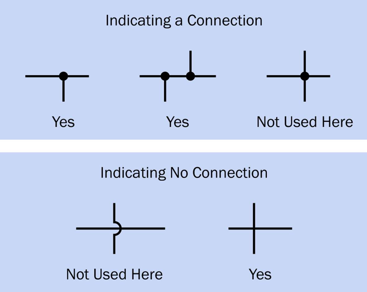
Figure 1. Top: In all the schematics in this book, conductors that make an electrical connection are joined with a black dot. However, the configuration at far right is avoided because it looks too similar to a crossover where there is no connection. Bottom: Conductors that cross one another without making a connection were shown in the style at left in Make: Electronics. The style at right is more common, and is used in this book.
Also in Make: Electronics I used the European convention for eliminating decimal points in component values. Thus, values such as 3.3K and 4.7K were expressed as 3K3 and 4K7. I still prefer this style, because decimal points can become hard to discern in a poorly printed schematic. However, some readers were confused by the European notation, so I have discontinued it in this book.
Dimensions
Integrated circuit chips (and many other parts) all used to be equipped with wire legs, properly known as “leads,” for insertion into holes in circuit boards. The leads on these “through-hole” components were spaced at intervals of 0.1″, and the components were reasonably easy to grasp and position with just your finger and thumb.
This idyllic vision of universal compatibility on a human scale was disrupted initially by an invasion from the metric system. Some manufacturers moved from a pin spacing of 2.54mm (the equivalent of 0.1″) to 2mm as the standard, causing frustration for those of us using 0.1″ perforated board. Millimeters popped up in other places, too. To take just one example, that most ubiquitous part, the panel-mounted LED, is often 5mm in diameter. This is a fraction too big for a 3/16″ hole, but not quite big enough to fit tightly in a 13/64″ hole.
Because this book is written and published in the United States, I generally use inches by preference. You will find a conversion table between millimeters and fractions of an inch in Make: Electronics.
A much more significant problem is that the entire electronics industry has moved toward surface-mount formats. Instead of a 0.1″ pin spacing, there are no pins at all, and a whole component is typically no longer than 0.1″. To build a circuit from these parts, you really need tweezers, a microscope, and a special soldering iron. It can be done, but personally I don’t find it enjoyable, and you will not find any projects in this book that use surface-mount components.
Math
You won’t find a lot of mathematics here, but you do need to understand the simple arithmetic that’s included.
I have chosen to use the style that’s common in programming languages. The * (asterisk) is used as a multiplication symbol, while the / (forward slash) is used as a division symbol. Where some terms are in parentheses, you deal with them first. Where parentheses are inside parentheses, you deal with the innermost ones first. So, in this example:
A = 30 / (7 + (4 * 2) )
You would begin by multiplying 4 times 2, to get 8; then add 7, to get 15; then divide that into 30, to get the value for A, which is 2.
Organization
Unlike the previous book, this one has a basically linear structure, mainly because it is more friendly toward handheld devices, which cannot handle the amount of detail and variety scattered around a double-page printed spread. I am hoping that you will progress through the book from beginning to end, instead of dipping into it here and there.
The first project establishes concepts that will be used in the second project, and the second project lays foundations for the third project. If you don’t follow this progression, you will run into some problems.
You will find five types of sections identified in subheads:
Experiments
Hands-on work is the main thread of the book.
Quick Facts
After I’ve introduced a new concept, I will often summarize some take-home messages for easy reference later.
Background
These are short detours from the main thread where I supply additional information that I think is interesting or useful, even though it may not be strictly necessary for building a project. After a brief description, I’ll leave you to pursue the topic on your own.
Make Even More
I don’t have space for thorough descriptions of all the possible construction projects, so I am including short summaries of others that I have considered.
Warnings
Once in a while I will have to mention something that you should try to avoid doing, either for the protection of the components that you are using, or to avoid an inconvenient error, or (rarely) to protect yourself.
If Something Doesn’t Work
Usually there is only one way to build a circuit that works, while there are hundreds of ways to make mistakes that will prevent it from working. Therefore the odds are against you, unless you proceed in a really careful and methodical manner. I know how frustrating it is when the components just sit there doing nothing, but if you have a problem, the following steps can usually help you to find the most common errors:
1. Attach the black lead from your meter to the negative side of the power supply, and set the meter to measure volts (DC volts, unless an experiment suggests otherwise). Make sure the power to your circuit is switched on. Now touch the red probe from your meter to various locations in the wiring, looking for erroneous voltages—or no voltage at all.
2. Check very carefully that all the jumper wires and component leads are exactly where they should be on the breadboard.
Two types of breadboarding errors are extremely common: inserting a jumper wire one row higher or one row lower than it should be, and placing two components or connections adjacent to each other on a single row, forgetting that the conductor inside the breadboard will short them together. Figure 2 illustrates these common problems. Please check that you fully understand them!
In the upper photograph, the leads of the electrolytic capacitor are inserted between rows 13 and 15 of the breadboard, but because they are hidden from this perspective, it’s easy to place one end of a blue jumper wire in row 14 by mistake. On the right, pin 5 of the chip is supposed to be grounded through a ceramic capacitor, but because all the holes along each row of the breadboard are connected internally, the capacitor is shorted out, and the chip is connected directly to ground. The lower photograph shows the errors corrected.
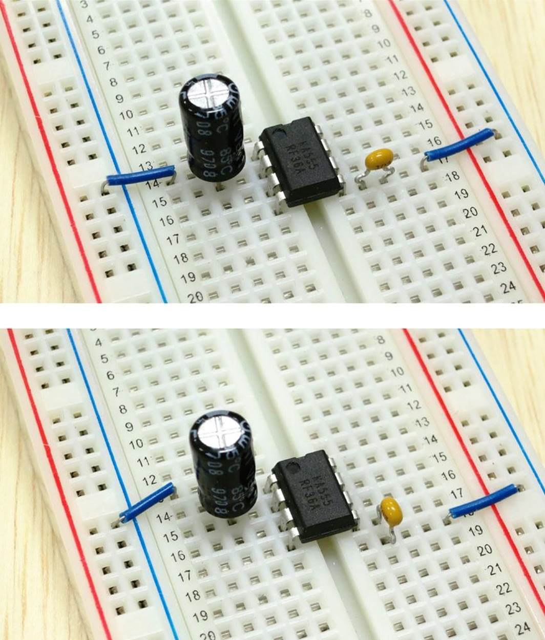
Figure 2. The two most common types of breadboarding errors are illustrated in the upper photograph, and are shown corrected in the lower photograph.
If power is being supplied correctly to your circuit, and components and wires are all placed correctly on the breadboard, here are five more possibilities to bear in mind:
Component orientation
Integrated circuit chips must be pushed down firmly into the board. Verify that no pin has been bent so that it is hidden underneath the chip. Diodes, and capacitors that have polarity, must be the right way around.
Bad connections
Sometimes (seldom, but it can happen) a component may make a bad connection inside the breadboard. If you have an inexplicable intermittent fault or zero voltage, try relocating some of the components. In my experience this problem is more likely to occur if you buy very cheap breadboards. It is also more likely if you use wire that has a smaller diameter than 24 gauge. (Remember, a higher gauge number means a thinner wire.)
Component values
Verify that all the resistor and capacitor values are correct. My standard procedure is to check each resistor with a meter before I plug it in. This is time-consuming but can save time in the long run. I’ll have more to say about this in the next section of the book.
Damage
Integrated circuits and transistors can be damaged by incorrect voltages, wrong polarity, or static electricity. Keep spares on hand so that you can make substitutions.
Human burnout
When all else fails, take a break! Working obsessively for long periods can create tunnel vision that prevents you from seeing what’s wrong. If you move your attention to something else for a while, then come back to your problem, the answer may suddenly appear obvious.
Writer-Reader Communication
There are three situations where I may want feedback from you, or you may want feedback from me. They are the following:
§ I may want to tell you if the book contains a mistake that will prevent you from building a project successfully. I may also want to tell you if a parts kit, sold in association with the book, has something wrong with it. Naturally, if a problem has been discovered, I’ll tell you how to deal with it. This is me-informing-you feedback.
§ You may want to tell me if you think you found an error in the book, or in a parts kit. This is you-informing-me feedback.
§ You may be having trouble making something work, and you don’t know whether I made a mistake or you made a mistake. You would like some help. This is you-asking-me feedback.
I will explain how to deal with each of these situations.
Me Informing You
I can’t notify you if there’s an error in the book or in a parts kit unless I have your contact information. Therefore I am asking you to send me your email address for the following purposes. Your email will not be used or abused for any other purpose:
§ I will notify you if any significant errors are found in this book or in its predecessor, Make: Electronics, and I will provide a workaround.
§ I will notify you of any errors or problems relating to kits of components sold in association with this book or Make: Electronics.
§ I will notify you if there is a completely new edition of this book, or of Make: Electronics, or of my other book Encyclopedia of Electronic Components. These notifications will be very rare, as a new edition may only appear every few years.
We’ve all seen those warranty cards that promise to enter you for a prize drawing. I’m going to offer you a much better deal. If you submit your email address, which may only be used for the three purposes listed, I will send you an unpublished electronics project with complete construction plans as a multipage PDF. It will be fun, it will be unique, and it will be relatively easy. You won’t be able to get this in any other way.
The reason I am encouraging you to participate is that if an error is found, and I have no way to tell you, and you discover it later on your own, you’re liable to get annoyed. This will be bad for my reputation and the reputation of my work. It is very much in my interest to avoid a situation where you have a complaint.
§ Simply send a blank email (or include some comments in it, if you like) to make.electronics@gmail.com. Please put REGISTER in the subject line.
You Informing Me
If you only want to notify me of an error that you have found, it’s really better to use the errata system maintained by my publisher. The publisher uses the errata information to fix the error in updates of the book.
If you are sure that you found an error, please visit:
http://oreil.ly/1jJr6DH
This web page will tell you how to submit errata.
You Asking Me
My time is obviously limited, and I can’t necessarily solve a problem for you. However, if you attach a photograph of a project that doesn’t work, I may have a suggestion. The photograph is essential. Trying to understand why something isn’t working, without being able to see it, is generally impossible.
You can use make.electronics@gmail.com for this purpose. Please put the word HELP in the subject line.
Before You Write
Before you report an error or tell me that something doesn’t work, I have a couple of requests:
§ Please rebuild the circuit at least once. Every project here was built by me and by a minimum of one other person before the book went into production, and while it’s not very polite for me to tell you that you may have screwed up, the most likely cause of a problem is always a wiring error.
Bear in mind that I made at least a dozen fatal wiring errors myself while building projects in this book. One error burned out a couple of chips. Another error partially melted a breadboard. Errors do happen, even to me, and even to you.
§ Please be aware of the power that you have as a reader, and use it fairly. A single negative review can create a bigger effect than you may realize. It can certainly outweigh half-a-dozen positive reviews. The responses that I received for Make: Electronics were generally very positive, but in a couple of cases people became annoyed over small issues such as being unable to find a part that I had recommended. In fact the parts were available, and I was happy to suggest sources, but in the meantime the negative reviews had appeared.
I do read my reviews on Amazon and will always provide a response if necessary.
Of course, if you simply don’t like the way in which I have written this book, you should feel free to say so.
Going Further
After you work your way through this book, I think you will be on your way to what I consider an intermediate understanding of electronics. I am not qualified to write an advanced guide, and consequently I don’t expect to create a third book with a title such as “Make Even More Electronics.”
If you still want to know more, the areas that I have avoided are electronics theory, circuit design, and circuit testing. If you create a circuit yourself, you should know enough theory to understand and predict what’s happening in it, and you should have the capability to discover how it is behaving after you have built it. To deal with this, you really need an oscilloscope and circuit simulation software. You will find a list of free software on Wikipedia. Some of these simulators show you the performance of digital circuits, some of them specialize in analog circuits, and some do both. But this topic is beyond the scope of a general book, and probably beyond the scope of most people who view electronics as a hobby rather than a career.
If you want to know more electrical theory, Practical Electronics for Inventors by Paul Scherz (McGraw-Hill, 2013) is still the book that I recommend most often. You don’t have to be an inventor to find it useful.
For reference, I have always felt that there’s a need for an encyclopedia of electronic components. I often wondered why a book of this type did not exist—and so I decided to write one myself.
Volume 1 of my Encyclopedia of Electronic Components is now available. There will be three volumes altogether. While Make: More Electronics is a hands-on tutorial, the encyclopedia format is designed to enable fast access to information. It is also a little more technical, and is written in a style that is less friendly but gets straight to the point. Personally I think an encyclopedia of components is an invaluable way to refresh your memory about the properties and applications of any parts that you are likely to use.
All materials on the site are licensed Creative Commons Attribution-Sharealike 3.0 Unported CC BY-SA 3.0 & GNU Free Documentation License (GFDL)
If you are the copyright holder of any material contained on our site and intend to remove it, please contact our site administrator for approval.
© 2016-2026 All site design rights belong to S.Y.A.