CCNP Routing and Switching ROUTE 300-101 Official Cert Guide (2015)
Part V. Router and Routing Security
Chapter 16. Fundamental Router Security Concepts
This chapter covers the following subjects:
 Elements of a Router Security Policy: This section defines a router security policy, explains why it is important to have one, and lists common elements comprising such a policy.
Access Control Lists: This section builds on your CCNA-level knowledge of standard, extended, and named access control lists (ACL) by introducing time-based ACLs and the concept of infrastructure ACLs.
Management Plane Security: This section discusses a collection of features and services available in Cisco IOS routers that can be used to better secure a router from attack.
Cisco uses the term defense-in-depth to describe an approach to network security having multiple layers of overlapping security mechanisms. One such layer of protection is the hardening (that is, more strictly enforcing security) of Cisco IOS routers. This chapter focuses on some of the techniques used to better secure these critical infrastructure devices. The first section of this chapter begins with a look at the importance of having a router security policy and what a policy might contain.
Next, this chapter builds on your CCNA-level knowledge of access control lists (ACL) and introduces time-based ACLs that are only active at specified times. Also, the chapter presents a best-practice recommendation for creating infrastructure ACLs (that is, ACLs that sit at the edge of a network and help protect a network infrastructure from external attacks).
The remainder of the chapter examines a collection of features and services that you can use to better secure a router’s management plane. These features and services include Secure Shell (SSH), password encryption, Unicast Reverse Path Forwarding (uRPF), AAA, SNMP security, and NTP authentication.
“Do I Know This Already?” Quiz
The “Do I Know This Already?” quiz allows you to assess whether you should read the entire chapter. If you miss no more than one of these eight self-assessment questions, you might want to move ahead to the “Exam Preparation Tasks” section. Table 16-1 lists the major headings in this chapter and the “Do I Know This Already?” quiz questions covering the material in those headings so that you can assess your knowledge of these specific areas. The answers to the “Do I Know This Already?” quiz appear in Appendix A.

Table 16-1 “Do I Know This Already?” Foundation Topics Section-to-Question Mapping
1. What mechanisms can be used to defend against IP spoofing? (Choose two.)
a. AAA
b. uRPF
c. CAR
d. ACLs
2. Which of the following features can provide router redundancy?
a. SNMP
b. HSRP
c. AAA
d. TACACS+
3. Identify two types of time-based ACLs. (Choose two.)
a. Reflexive
b. Periodic
c. Absolute
d. Adaptive
4. What term is given to an ACL that typically resides on a network’s boundary routers (that is, routers facing another autonomous system), which is designed to protect a network from malicious traffic?
a. Time-based ACL
b. Reflexive ACL
c. Absolute ACL
d. Infrastructure ACL
5. When configuring a router to support SSH connections, which of the following are used in generating an RSA key pair? (Choose two.)
a. Host name
b. Router ID
c. Domain name
d. Configuration revision number
6. Which type of Cisco IOS password encryption uses the Vigenere cipher?
a. Type 0
b. Type 4
c. Type 5
d. Type 7
7. Which mode of uRPF causes a router interface to accept a packet, if the network to which the packet’s source IP address belongs is found in the router’s FIB?
a. Strict mode
b. Loose mode
c. Auto mode
d. Desirable mode
8. Which of the following are characteristics of TACACS+? (Choose two.)
a. Uses UDP
b. Encrypts an entire packet
c. Offers robust accounting
d. Cisco-proprietary
Foundation Topics
Elements of a Router Security Policy
In today’s enterprise networks, routers often sit at the edge of the network, connecting out to other sites. As a result, they often come under a multitude of attacks.
Because these precariously positioned devices reside at a critical line of defense, Cisco recommends that you have a documented plan detailing how your routers are secured. Having a formalized approach to router security helps ensure a consistent configuration across multiple devices and helps identify potential security weaknesses.
A document defining the security features deployed on a router is called a router security policy. While the elements of a router security policy can vary from network to network, the following list provides a collection of security topics commonly addressed in a router security policy:

Passwords: Will passwords appear encrypted in the router’s running configuration? How often should passwords be changed? How complex should passwords be?
Authentication: Will users be authenticated by a router’s local database or by an external authentication, authorization, and accounting (AAA) server (for example, a TACACS+ or RADIUS server)? Will a AAA server be used to log login and logout events? Will a banner be presented to someone logging in, letting him know that only authorized users should attempt to log in?
Access: When administrators remotely connect to the router, what protocols are they allowed to use (for example, SSH, HTTPS, Telnet, HTTP)? If Simple Network Management Protocol (SNMP) is configured to use community strings for authentication, how often should those community strings be changed?
Services: What services currently running on the router are unneeded and should be disabled?
Filtering: Are private IP addresses (as defined in RFC 1918) being filtered? How is the router configured to defend against IP spoofing attacks, where a malicious user on a remote network makes his source IP address appear to be a trusted IP address? (Examples of antispoofing mechanisms include ACLs and uRPF.)
Routing protocols: What kind of authentication (if any) is used by the router’s routing protocol(s)?
Backups: How is the router configuration backed up (for example, to a TFTP server)? How often does this backup occur?
Documentation: What procedure is in place to ensure that all router configuration changes are documented?
Redundancy: If a router fails, is there a backup router to take over? If there is a backup router, is it a hot standby router (for example, a router that is currently running and configured with a first-hop redundancy protocol such as Hot Standby Router Protocol [HSRP]) or a cold standby router (for example, a router that was on-site, but was not necessarily powered on or configured)?
Monitoring: What parameters are being monitored and logged (for example, CPU utilization, memory utilization, and failed access attempts)?
Updates: What procedure is in place to determine whether security vulnerabilities have been identified in the version of Cisco IOS running on the router? What procedure is in place to update the version of Cisco IOS running on the router?
Note
This book lightly touches on router and network security topics; however, router and network security are much larger fields of study. If you are interested in learning more about router and network security, consider taking the courses or reading the books in the Cisco CCNA Security and CCNP Security tracks.
Access Control Lists
In your CCNA studies, you learned about access control lists (ACL). Specifically, you learned how standard ACLs could match traffic based on source IP addresses and how extended ACLs could match traffic based on source IP addresses, destination IP addresses, and a variety of other criteria such as port numbers. You also learned how to create numbered or named ACLs. These ACLs are frequently used to protect a router’s data plane (that is, to filter traffic traveling through a router). However, ACLs can also be used to help protect the management plane and the control plane.
The ROUTE exam blueprint requires that you remember these fundamental ACL concepts. Additionally you need to know how to configure time-based ACLs. This section introduces you to time-based ACLs and illustrates how to create infrastructure ACLs, which are applied to routers sitting at the edge of an enterprise network.
Time-Based ACLs
You might want to allow specific protocols to come into your network during business hours, but not outside of business hours. For example, imagine that a company has an internal web server that it wants to be accessible to its remote employees during working hours (that is, Monday through Friday from 8:00 a.m. to 5:00 p.m.). You could accomplish such a design goal through the use of time-based ACLs, which are only in effect during a specified time range.
Note
A time range configured on a router references a router’s clock. Therefore, a best practice is to configure Network Time Protocol (NTP) on a router, which can help ensure that the router’s internal clock has the correct time.
A time range can be periodic, where it becomes active or inactive at specific times of the day on specific days of the week. Alternately, a time range can be absolute, where there is a fixed starting and stopping date and time during which the ACL is active. Table 16-2 presents a list of commands used in creating a time-based ACL.
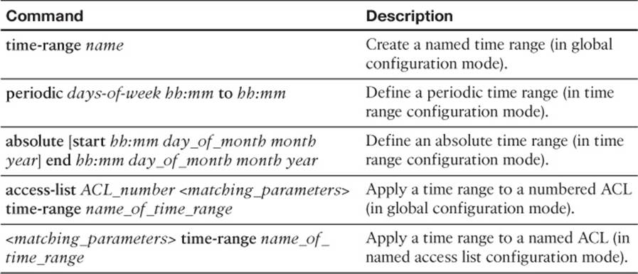
Table 16-2 Time-Based ACL Commands
Consider the topology presented in Figure 16-1, where an enterprise network needs remote employees to access an internal web server Monday through Friday from 8:00 a.m. to 5:00 p.m.
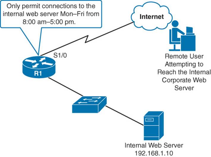
Figure 16-1 Web Server with Time-Based Access Permissions
Example 16-1 shows the configuration on Router R1 that supports time-based access to the internal web server for an external user.
Example 16-1 Time-Based ACL Configuration Example
R1# conf term
R1(config)# time-range WEEKDAYS
R1(config-time-range)# periodic ?
Friday Friday
Monday Monday
Saturday Saturday
Sunday Sunday
Thursday Thursday
Tuesday Tuesday
Wednesday Wednesday
daily Every day of the week
weekdays Monday thru Friday
weekend Saturday and Sunday
R1(config-time-range)# periodic weekdays 8:00 to 17:00
R1(config-time-range)# exit
R1(config)# access-list 100 permit tcp any host 192.168.1.10 eq 80 time-range
WEEKDAYS
... OUTPUT OMITTED FOR OTHER PERMIT ACL STATEMENTS NOT RELEVANT TO THIS EXAMPLE ...
R1(config)# interface serial 1/0
R1(config-if)# ip access-group 100 in
R1(config-if)# end
In Example 16-1, a time range named WEEKDAYS was created. Context-sensitive help revealed that a keyword of weekdays could be used to specify the days Monday through Friday, without the need to list each day. An extended access list, numbered 100, was created to permit traffic to IP address 192.168.1.10 (that is, the internal web server) on TCP port 80, and the time range of WEEKDAYS was applied.
Infrastructure ACLs
An infrastructure ACL is typically an extended ACL that is applied to routers residing on the outer edges of an enterprise network. The primary purpose of this ACL is to prevent malicious traffic from entering the enterprise. As an example, an infrastructure ACL could be used to block packet fragments while permitting packets being exchanged with trusted Border Gateway Protocol (BGP) peers, management stations, and transit traffic (that is, traffic whose source and destination are both off-net).
Although the specific elements present in an infrastructure ACL can vary widely from network to network, Example 16-2 shows a sample infrastructure ACL configuration.
Example 16-2 Sample Infrastructure ACL
ip access-list extended INFRASTRUCTURE
!
! BLOCK PACKET FRAGMENTS
deny tcp any any fragments
deny udp any any fragments
deny icmp any any fragments
deny ip any any fragments
!
! ALLOW NECESSARY ROUTING PROTOCOL
! AND NETWORK MANAGMENT TRAFFIC
permit tcp host <external-bgp-peer> host <internal-bgp-peer> eq bgp
permit tcp host <external-bgp-peer> eq bgp host <internal-bgp-peer>
permit tcp <address-of-management-stations> any eq 22
permit tcp <address-of-management-stations> any eq 161
permit icmp <address-of-management-stations> any echo
!
! BLOCK ALL OTHER TRAFFIC DESTINED FOR INTERNAL NETWORK
deny ip any <address-space-of-internal-network>
!
! PERMIT OFF-NET TO OFF-NET TRAFFIC
permit ip any any
!
! APPLY ACL IN THE INBOUND DIRECTION TO AN INTERFACE
! CONNECTING TO AN EXTERNAL NETWORK
interface Serial1/0
ip access-group INFRASTRUCTURE in
To make Example 16-2 simpler to understand, variables (which are in italics) representing IP addresses and network address spaces are used instead of actual IP addresses. In the example, an ACL named INFRASTRUCTURE was created. A collection of deny statements was then given to block packet fragments. Next, a series of permit statements was given to allow peering with an external BGP router (possibly a service provider’s router), SSH and SNMP connections from trusted management stations, and pings from trusted management stations. All other traffic destined for internal IP addresses was denied, while traffic that originated off-net and was destined for an off-net IP address was permitted. The INFRASTRUCTURE ACL was then applied in the inbound direction to an Internet-facing interface (interface Serial 1/0 in this example).
Management Plane Security
As mentioned in Chapter 11, “Route Selection,” a router’s architecture can be categorized into three operational planes:
Management plane: The management plane is concerned with the management of the device. For example, an administrator connecting to a router through a Secure Shell (SSH) connection through one of the router’s VTY lines would be a management plane operation.
Control plane: The control plane is concerned with making packet-forwarding decisions. For example, routing protocol operation would be a control plane function.
Data plane: The data plane is concerned with the forwarding of data through a router. For example, end-user traffic traveling from a user’s PC to a web server on a different network would go across the data plane.
The ROUTE exam blueprint requires that you know how to protect each of these planes. This chapter discusses approaches for protecting the management plane. Chapter 17, “Routing Protocol Authentication,” covers control plane security, by performing authentication for a variety of routing protocols. Finally, you should be familiar with access control lists (ACL) to protect the data plane. ACLs were discussed in your CCNA studies.
Secure Shell Versus Telnet
Many network engineers commonly use Telnet to remotely connect to their routers; however, Cisco strongly recommends using Secure Shell (SSH) instead of Telnet.
The issue with Telnet is that it sends data (including passwords) across a network in clear text. This opens the door for a malicious user to launch a man-in-middle attack and use packet capture software to read the contents of the Telnet session’s packets.
Fortunately, SSH encrypts this traffic. So, even if a malicious user did capture packets from the SSH session, the packets would be unreadable.
The steps to configure SSH on a router are as follows:
Step 1. Specify a host name for the router, with the hostname name command in global configuration mode. (The host name is one of the elements used to create an RSA key pair.)
Step 2. Specify a domain name for the router with the ip domain-name domain_name command in global configuration mode. (The domain name is one of the elements used to create an RSA key pair.)
Step 3. Create a username and password for a user with a privilege level of 15 using the username username privilege 15 secret password global configuration mode command.
Step 4. Generate an RSA key pair with the crypto key generate rsa modulus size_of_modulus command in global configuration mode.
Step 5. Use the transport input ssh command in VTY line configuration mode to make SSH the only supported VTY transport protocol.
Step 6. Issue the login local command in VTY line configuration mode to tell SSH to use a router’s local user database for authentication.
Step 7. (Optional) Use the access-class acl in command in VTY line configuration mode to limit VTY access to IP addresses matched by the specified ACL.
Example 16-3 illustrates a sample SSH configuration on Router R1, as shown in Figure 16-2.
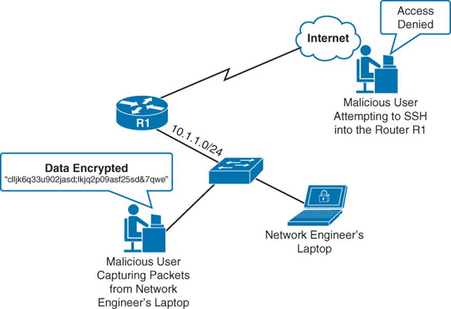
Figure 16-2 Defending Against Unauthorized VTY Access
Example 16-3 Enabling SSH for VTY Access
hostname R1
ip domain-name 1ExamAMonth.com
!
crypto key generate rsa modulus 2014
!
username kevin privilege 15 secret cisco
!
access-list 1 permit 10.1.1.0 0.0.0.255
access-list 1 deny any log
!
line vty 0 15
access-class 1 in
login local
transport input ssh
Figure 16-2 shows a network engineer’s laptop on subnet 10.1.1.0 /24 that currently has an SSH session open to Router R1; however, a malicious user located on the same subnet is capturing packets from the SSH session (possibly after a man-in-the-middle attack). Fortunately, the network engineer used SSH to connect to the router, causing the packets captured by the malicious user to be unreadable.
Another malicious user, located somewhere on the Internet, is attempting to set up an SSH session with Router R1, possibly using a program that does a brute-force attack (that is, repeatedly trying different passwords until the correct password is determined). Fortunately, this user is not even presented with a login prompt, because an access class has been configured for the router’s VTY lines that does not permit connections from any source IP address not on the 10.1.1.0 /24 subnet.
Example 16-3 shows Router R1’s configuration that allows it to defend against the malicious users pictured in Figure 16-1. First, the host name is set to R1 and the domain name is set to 1ExamAMonth.com. These values are used in the calculation of the RSA key pair, which is initiated with the crypto key generate rsa modulus 2014 command. Note that you can use different modulus lengths in the range 260–4096. However, longer lengths are considered more secure.
A username of kevin with a password of cisco was created, and that user account was given a privilege level of 15, which is the highest privilege level. An access list was then created to match IP addresses in the 10.1.1.0 /24 subnet.
In VTY line configuration mode, the transport input ssh command causes the VTY lines to accept only SSH connections. The access-class 1 in command tells the VTY lines to accept only those connections coming from IP addresses matched by ACL 1. Finally, the login local command tells SSH to use the router’s local database (as populated with the username command) for authentication.
Password Encryption
Ideally, all passwords associated with your routers would be stored on an external AAA server; however, it is often necessary to locally store passwords on a router. If someone were to see that router’s running configuration, she would be able to see any of those passwords, if they were in clear text. Therefore, a best-practice security recommendation is to encrypt any passwords appearing in a router’s configuration.
Cisco IOS has a few different passwords that you might want to encrypt (or represent as a hash value), including the enable secret password, line password, and username password.
Enable Secret Password
The enable secret password can be used to give a network engineer full privileges on a router. This password is configured with the enable secret password global configuration mode command. The password then appears in a router’s running configuration as a Secure Hash Algorithm–256 (SHA-256) hash value, which is very difficult to reverse, even if it did fall into the hands of a malicious user.
Example 16-4 shows the configuration and verification of an enable secret password.
Example 16-4 Enable Secret Password Configuration and Verification
R1# conf term
R1(config)# enable secret cisco
R1(config)# end
R1# show run
...OUTPUT OMITTED...
enable secret 4 tnhtc92DXBhelxjYk8LWJrPV36S2i4ntXrpb4RFmfqY
In Example 16-4, an enable secret password of cisco is configured on Router R1. The running configuration then shows the SHA-256 hash of the password. The 4 indicates that the string is an SHA-256 hash. On some older versions of Cisco IOS, you will see a 5 there instead of a 4. A 5indicates that the hash is a Message Digest 5 (MD5) hash, which is not considered as secure as SHA-256.
Note
If you happen to know the MD5 or SHA-256 hash of the password you want to use, you can specify the actual hash as part of the enable secret command. Specifically, you could use the enable secret 5 md5-hash command to specify an MD5 hash for a password. Alternately, you could use the enable secret 4 sha-256-hash command to specify an SHA-256 hash for a password.
Line Password
A line password is used to authenticate a user attempting to log in to one of the router’s lines; for example, a VTY (virtual TTY) line, the console line, or the auxiliary line. You can define a line password in line configuration mode with the password password command; however, at that point, the password still shows up in the router’s running configuration in clear text. To encrypt that password, you can issue the service password-encryption command in global configuration mode. Unfortunately, this type of encryption is not very strong. It uses the Vigenere cipher and is also known as Type 7 encryption. While this type of encryption can protect passwords from a casual observer who happens to catch a glimpse of the password, it can easily be deciphered (using freely available utilities on the Internet) if someone were to come into possession of a router’s running configuration. Therefore, Cisco recommends configuring username/password combinations (discussed in the next section) and requiring those credentials to be entered before accessing one of the router’s lines.
Example 16-5 shows the configuration and verification of a line password for the console line. The example continues to show the configuration and verification of Type 7 encryption.
Example 16-5 Line Password Configuration and Verification
R1# conf term
R1(config)# line con 0
R1(config-line)# password cisco
R1(config-line)# login
R1(config-line)# end
R1# show run | s line
line con 0
password cisco
login
... OUTPUT OMITTED ...
R1# conf term
R1(config)# service password-encryption
R1(config)# end
R1# show run | s line
line con 0
password 7 1511021F0725
... OUTPUT OMITTED ...
In Example 16-5, a line password of cisco is configured for the console 0 line. The login command enables the ability for someone to log in to the console port, supplying the configured password as his only authentication credential. However, as seen in the running configuration, the password was not encrypted. Therefore, the example then shows the service password-encryption command being entered, which does encrypt the password. Unfortunately, the type of encryption used is Type 7 encryption, which is very weak encryption. A more preferable approach (as demonstrated in the next section) is to authenticate users based on a username/password combination, where the password appears in the running configuration as an SHA-256 hash value.
Username Password
Instead of just requiring a password to log in to a router, you can create a username/password combination that a network engineer must enter to gain access to the router. Usernames can also be configured with various privilege levels (where a privilege level of 15 indicates a full set of privileges). These privilege levels can be used to control what Cisco IOS commands a user can execute.
You can populate a locally stored user database with the command username username privilege privilege secret password. This causes an SHA-256 hash of the password to appear in the router’s running configuration, which is vastly more secure than Type 7 encryption.
Example 16-6 shows the configuration and verification of creating a local user and allowing that user account to access a router’s VTY lines.
Example 16-6 Local User Account Creation and Verification
R1# conf term
R1(config)# username kevin privilege 15 secret cisco
R1(config)# line vty 0 15
R1(config-line)# login local
R1(config-line)# end
R1# show run
... OUTPUT OMITTED ...
!
username kevin privilege 15 secret 4 tnhtc92DXBhelxjYk8LWJrPV36S2i4ntXrpb4RFmfqY
!
... OUTPUT OMITTED ...
!
line vty 0 15
login local
... OUTPUT OMITTED ...
Example 16-6 shows the configuration of a username of kevin with a password of cisco. The login local command issued in line configuration mode tells the VTY lines to use the router’s local user account database for authentication. This is as opposed to only using a password configured in line configuration mode for authentication, as was seen in Example 16-5. Notice that the password appears in the running config as an SHA-256 hash of the password, as evidenced by the 4 preceding the hash. On some older versions of Cisco IOS, you might instead see a 5 preceding the hash, indicating an MD5 hash.
Unicast Reverse Path Forwarding
One approach to preventing malicious traffic from entering a network is to use Unicast Reverse Path Forwarding (uRPF). Specifically, uRPF can help block packets having a spoofed IP address. The way that uRPF works is to check the source IP address of a packet arriving on an interface and determine whether that IP address is reachable, based on the router’s Forwarding Information Base (FIB) used by Cisco Express Forwarding (CEF). Optionally, the router can also check to see whether the packet is arriving on the interface the router would use to send traffic back to that IP address.
Note
CEF must be enabled on a router to use uRPF.
You can choose between three modes of operation for uRPF:
Strict mode: With strict mode operation, a router not only checks to make sure that the source IP address of an arriving packet is reachable, based on the router’s FIB, but the packet must also be arriving on the same interface the router would use to send traffic back to that IP address.
Loose mode: With loose mode operation, a router only verifies that the source IP address of a packet is reachable, based on the router’s FIB.
VRF mode: Virtual Routing and Forwarding (VRF) is a technology that allows a router to have multiple IP routing table instances, thus allowing overlapping IP addresses to be used. uRPF operating in VRF mode (also known as uRPF version 3 or uRPFv3) is similar to loose mode operation in that source IP addresses are checked against the FIB for a specific VRF.
Note
Based on the scope of the ROUTE exam blueprint, this book covers the configuration and verification of strict mode and loose mode.
From a design perspective, strict mode could cause traffic to be dropped if an asynchronous routing situation exists (that is, traffic from a network address space might be received on one router interface, but traffic to that same network address space might be transmitted out of a different router interface). Therefore, strict mode should typically be used where there is no chance of asynchronous routing (for example, a branch office with only one connection going back to a corporate headquarters).
Some IP routing tables (and therefore, the associated FIBs) might not have explicit entries for individual networks with which they communicate. Instead, a default route might be used. In such a situation, would a router configured with uRPF drop an arriving packet if the network for that packet’s source IP address was not present in the router’s FIB?
By default, a router with uRPF configured would drop a packet whose source IP address was only reachable by a default route; however, uRPF supports an allow-default option that accepts a default route as a valid way to get back to a source IP address.
To further fine-tune uRPF operation, you can configure an ACL and reference that ACL in the uRPF configuration command. If you do reference an ACL, it is checked only when a uRPF check fails. After a uRPF check failure, if a packet is matched and permitted by the associated ACL, it is transmitted. If a packet fails the uRPF check and is denied by the associated ACL, however, the packet is dropped.
The command used to configure uRPF in interface configuration mode is as follows:
ip verify unicast source reachable-via {rx | any} [allow-default] [allow-self-
ping] [acl]
Table 16-3 describes the parameters of this command.
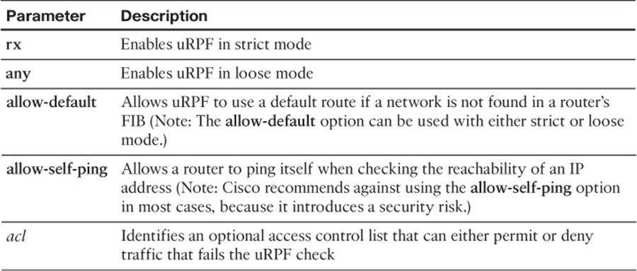
Table 16-3 uRPF Configuration Parameters
To illustrate the configuration of uRPF, consider Figure 16-3 and Examples 16-7 and 16-8.
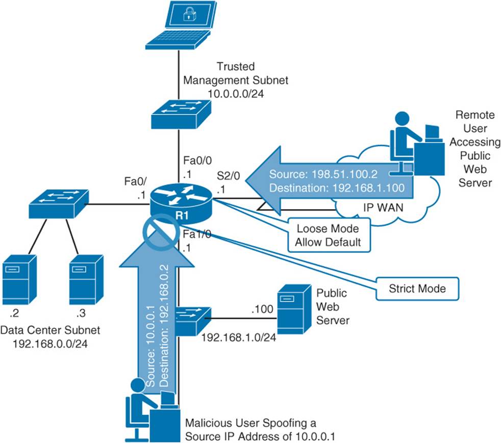
Figure 16-3 uRPF Sample Topology
Example 16-7 uRPF Sample Configuration
interface FastEthernet1/0
ip address 192.168.1.1 255.255.255.0
ip verify unicast source reachable-via rx
!
... OUTPUT OMITTED ...
!
interface Serial2/0
ip address 172.16.0.1 255.255.255.252
ip verify unicast source reachable-via any allow-default
Example 16-8 Router R1’s FIB
R1# show ip cef
Prefix Next Hop Interface
0.0.0.0/0 172.16.0.2 Serial2/0
0.0.0.0/8 drop
0.0.0.0/32 receive
10.0.0.0/24 attached FastEthernet0/0
10.0.0.0/32 receive FastEthernet0/0
10.0.0.1/32 receive FastEthernet0/0
10.0.0.255/32 receive FastEthernet0/0
127.0.0.0/8 drop
172.16.0.0/30 attached Serial2/0
172.16.0.0/32 receive Serial2/0
172.16.0.1/32 receive Serial2/0
172.16.0.2/32 attached Serial2/0
172.16.0.3/32 receive Serial2/0
192.168.0.0/24 attached FastEthernet0/1
192.168.0.0/32 receive FastEthernet0/1
192.168.0.1/32 receive FastEthernet0/1
192.168.0.255/32 receive FastEthernet0/1
192.168.1.0/24 attached FastEthernet1/0
192.168.1.0/32 receive FastEthernet1/0
192.168.1.1/32 receive FastEthernet1/0
192.168.1.255/32 receive FastEthernet1/0
Prefix Next Hop Interface
224.0.0.0/4 drop
224.0.0.0/24 receive
240.0.0.0/4 drop
255.255.255.255/32 receive
In the preceding example, a malicious user on the 192.168.1.0 /24 network is spoofing his IP address. Specifically, he is sending packets to a server (with an IP address of 192.168.0.2) in the data center subnet, and he is altering his source IP address to 10.0.0.1. The reason for this IP spoofing is so that the user’s traffic will appear to come from the trusted management subnet of 10.0.0.0 /24 (which has permission to access the data center servers). However, as his traffic enters interface Fa 1/0 on Router R1, uRPF (configured for strict mode) checks to see what interface would be used to send traffic back to an IP address of 10.0.0.1. As seen in Example 16-8, Router R1’s FIB indicates that traffic destined for 10.0.0.1 would go out of interface Fa 0/0. Because the received traffic is being received on interface Fa 1/0, the uRPF check fails and the traffic is dropped.
Also, a remote user with an IP address of 198.51.100.2 is attempting to access a public web server with an IP address of 192.168.1.100. Traffic from the remote user enters Router R1 on interface Serial 2/0. This interface has been configured with uRPF in loose mode, along with the allow-default option. As seen in Example 16-8, Router R1’s FIB does not have a specific entry for this user’s network. However, there is a default route in the FIB (that is, the 0.0.0.0/0 route). Because uRPF configured on interface Serial 2/0 is using the allow-default option, the default route is considered to be a route that matches the source IP address. Therefore, the traffic from this remote user is permitted into Router R1.
You can use the show cef interface interface_id command to determine whether uRPF is enabled on an interface. Example 16-9 shows the output of this command for both interface Fa 1/0 and Serial 2/0.
Example 16-9 uRPF Verification
R1# show cef interface fa 1/0
FastEthernet1/0 is up (if_number 4)
Corresponding hwidb fast_if_number 4
Corresponding hwidb firstsw->if_number 4
Internet address is 192.168.1.1/24
ICMP redirects are always sent
Per packet load-sharing is disabled
IP unicast RPF check is enabled
Input features: uRPF
IP policy routing is disabled
BGP based policy accounting on input is disabled
BGP based policy accounting on output is disabled
Hardware idb is FastEthernet1/0
Fast switching type 1, interface type 18
IP CEF switching enabled
IP CEF switching turbo vector
IP CEF turbo switching turbo vector
IP prefix lookup IPv4 mtrie 8-8-8-8 optimized
Input fast flags 0x4000, Output fast flags 0x0
ifindex 4(4)
Slot Slot unit 0 VC -1
IP MTU 1500
R1# show cef interface s 2/0
Serial2/0 is up (if_number 6)
Corresponding hwidb fast_if_number 6
Corresponding hwidb firstsw->if_number 6
Internet address is 172.16.0.1/30
ICMP redirects are never sent
Per packet load-sharing is disabled
IP unicast RPF check is enabled
Input features: uRPF, iEdge
Output features: iEdge
IP policy routing is disabled
BGP based policy accounting on input is disabled
BGP based policy accounting on output is disabled
Interface is marked as point to point interface
Hardware idb is Serial2/0
Fast switching type 7, interface type 70
IP CEF switching enabled
IP CEF switching turbo vector
IP CEF turbo switching turbo vector
IP prefix lookup IPv4 mtrie 8-8-8-8 optimized
Input fast flags 0x10004000, Output fast flags 0x100000
ifindex 6(6)
Slot Slot unit 0 VC -1
IP MTU 1500
Authentication, Authorization, and Accounting
Enforcing router login security in larger networks can be challenging if you have to manage multiple user databases (for example, having a separate user database locally configured on each router of your network). Fortunately, with AAA (authentication, authorization, and accounting) services, you can have a single repository for user credentials. Then, when a network engineer attempts to log in to, for example, a router, the credentials that she supplies can be authenticated against a centralized AAA database.
Another advantage of giving different network administrators their own login credentials, as opposed to an enable secret password used on all routers, is that users can quickly be added and deleted from the database without the need to reconfigure each router. Not only can AAA service administrative logins connecting to a router, but AAA can also control connections passing through a router to, for example, resources inside a network.
Three services are offered by a AAA server, as follows:
Authentication: The authentication service can check a user’s credentials to confirm he is who he claims to be.
Authorization: After being authenticated, the authorization service determines what that user is allowed to do.
Accounting: The accounting service can collect and store information about a user’s login. This information can be used, for example, to keep an audit trail of what a user did on the network.
Figure 16-4 shows a AAA topology where only authentication is being performed. The user at an IP address of 192.168.1.50 is attempting to establish a Telnet session with a router at an IP address of 10.3.3.2. The router’s configuration, shown in Example 16-10, causes Router R1 to prompt a user for username and password credentials and to check those credentials against a AAA server (a TACACS+ server in this example, as opposed to a RADIUS server). If the provided credentials match the database being referenced by the AAA configuration, the user is permitted to log in to the router.
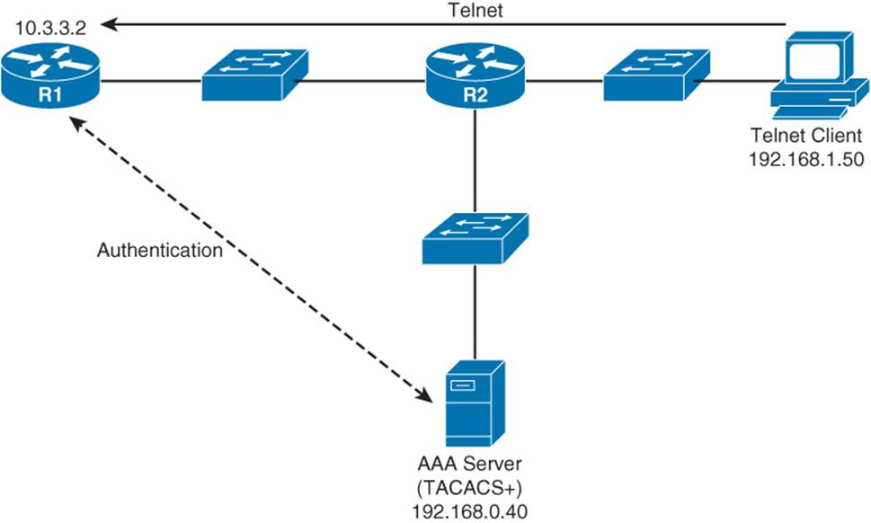
Figure 16-4 AAA Sample Topology
Example 16-10 AAA Configuration for Authenticating Remote Logins
aaa new-model
aaa authentication login ADMIN group tacacs+ local
!
username kevin secret cisco
!
tacacs server CISCO-ACS
address ipv4 192.168.0.40
key cisco
!
line vty 0 4
login authentication ADMIN
In the previous example, the aaa new-model command is used to enable AAA services on the router. The aaa authentication login ADMIN group tacacs+ local command defines a method list named ADMIN, which attempts to perform authentication through a TACACS+ server. However, if the TACACS+ is unavailable, the local key work instructs the router to perform authentication using the local user database (which includes the user kevin with a password of cisco in this example).
The TACACS+ server is defined as having an IP address of 192.168.0.40 with a shared secret key of cisco. The method list of ADMIN is then applied as the authentication method list for connections coming into the router over VTY lines 0 through 4. Therefore, when someone attempts to Telnet into this router, she is challenged to provide valid username and password credentials, which are then validated by the TACACS+ server or the router’s local user database if the TACACS+ server is not available.
Note
The Cisco IOS implementation of AAA services includes multiple configuration options, and a comprehensive discussion of AAA is beyond the scope of the ROUTE exam blueprint. For more information on AAA configuration, consult the Cisco “Authentication, Authorization, and Accounting Configuration Guide” available at the following URL: http://bit.ly/aaaconfig.
While Example 16-10 used a TACACS+ server as an external AAA server, another option is to use a RADIUS server. Table 16-4 compares these two authentication protocols.
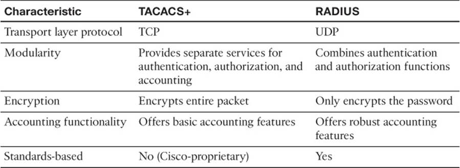
Table 16-4 Contrasting the TACACS+ and RADIUS Protocols
SNMP Security
The first Request for Comments (RFC) for SNMP came out in 1988. Since then, SNMP has become the de facto standard for network management protocols. The original intent for SNMP was for SNMP to manage network nodes, such as network servers, routers, switches, and hubs. SNMP version 1 (SNMPv1) and SNMP version 2c (SNMPv2c) specify three major components of an SNMP solution, as detailed in Table 16-5.
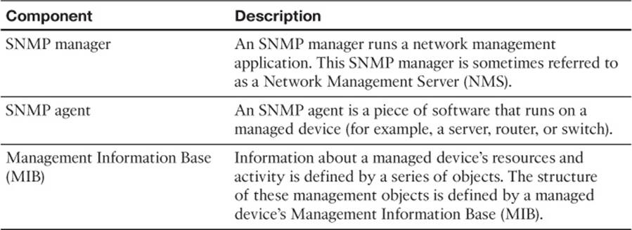
Table 16-5 Components of an SNMPv1 and SNMPv2c Network Management Solution
As depicted in Figure 16-5, an SNMP manager (an NMS) can send information to, request information from, or receive unsolicited information from a managed device (a managed router in this example). The managed device runs an SNMP agent and contains a MIB.
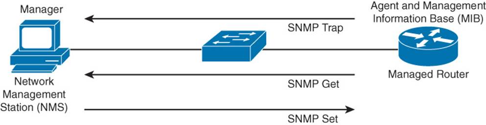
Figure 16-5 SNMPv1 and SNMPv2c Network Management Components and Messages
Even though multiple SNMP messages might be sent between an SNMP manager and a managed device, consider the three broad categories of SNMP message types:
GET: An SNMP GET message retrieves information from a managed device.
SET: An SNMP SET message sets a variable in a managed device or triggers an action on a managed device.
Trap: An SNMP Trap message is an unsolicited message sent from a managed device to an SNMP manager, which can notify the SNMP manager about a significant event that occurred on the managed device.
SNMP offers security against malicious users attempting to collect information from a managed device, changing the configuration of a managed device, or intercepting information being sent to an NMS. However, the security integrated with SNMPv1 and SNMPv2c is considered weak. Specifically, SNMPv1 and SNMPv2c use community strings to gain read-only or read-write access to a managed device. You can think of a community string as being much like a password. Also, be aware that multiple SNMP-compliant devices on the market today have a default read-only community string of public and a default read-write community string of private. As a result, such devices, left at their default SNMP settings, might be compromised.
Note
This section refers to SNMPv2c as opposed to SNMPv2. SNMPv2 contained security enhancements in addition to other performance enhancements. However, few network administrators adopted SNMPv2 because of the complexity of the newly proposed security system. Instead, Community-Based Simple Network Management Protocol (SNMPv2c) gained widespread acceptance, because SNMPv2c included the feature enhancements of SNMPv2 without using SNMPv2’s complex security solution. Instead, SNMPv2c kept the SNMPv1 concept of community strings.
If you do need to secure an SNMPv1 or SNMPv2c environment, you should change the community strings to nondefault values and possibly reference an ACL. The ACL could match a trusted subnet of management stations or a specific IP address of a management station. To illustrate how to better secure SNMPv1 and SNMPv2c router configurations, consider Example 16-11.
Example 16-11 Securing SNMPv1 and SNMPv2c
R1(config)# snmp-server community $3cr3T ro 10
R1(config)# snmp-server community c1$c0 rw 10
R1(config)# access-list 10 permit host 10.1.1.1
In Example 16-11, the read-only and read-write community strings (as specified with the ro and rw options) are being set to nondefault values, and the snmp-server community commands are referencing ACL 10, which is matching a trusted network management station with an IP address of 10.1.1.1. With this configuration, even if the community strings were compromised, an attacker would still have to appear to have an IP address of 10.1.1.1.
Fortunately, the security weakness of SNMPv1 and SNMPv2c are addressed in SNMPv3. To better understand these security enhancements, consider the concept of a security model and a security level:
Security model: Defines an approach for user and group authentications (for example, SNMPv1, SNMPv2c, and SNMPv3).
Security level: Defines the type of security algorithm performed on SNMP packets. The three available security levels are
noAuthNoPriv: The noAuthNoPriv (no authentication, no privacy) security level uses a username for authentication and does not use encryption to provide privacy.
authNoPriv: The authNoPriv (authentication, no privacy) security level provides authentication using Hash Message Authentication Code (HMAC) with MD5 or SHA-1. However, no encryption is used.
authPriv: The authPriv (authentication, privacy) security level offers HMAC MD5 or SHA-1 authentication and provides privacy through encryption. Specifically, the encryption uses the Data Encryption Standard (DES), Triple DES (3DES), or Advanced Encryption Standard (AES) algorithm.
As summarized in Table 16-6, SNMPv3 supports all three security levels. Notice that SNMPv1 and SNMPv2c only support the noAuthNoPriv security level.
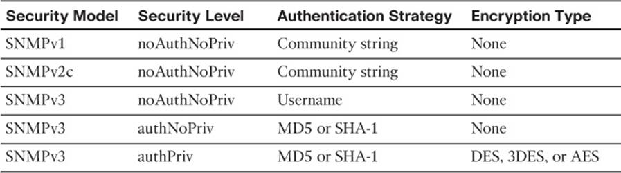
Table 16-6 Security Models and Security Levels Supported by Cisco IOS
Through the use of security algorithms, as shown in Table 16-6, SNMPv3 dramatically increases the security of network-management traffic, as compared to SNMPv1 and SNMPv2c. Specifically, SNMPv3 offers three primary security enhancements:
Integrity: Using hashing algorithms, SNMPv3 ensures that an SNMP message was not modified in transit.
Authentication: Hashing allows SNMPv3 to validate the source of an SNMP message.
Encryption: Using the DES, 3DES, or AES encryption algorithm, SNMPv3 provides privacy for SNMP messages, making them unreadable by an attacker who might capture SNMP packets.
NTP Authentication
Imagine that you are reviewing device logs collected in a router’s buffer and are attempting to correlate the events in the device logs with an issue that you are troubleshooting. To make that correlation, the logged events need to have accurate timestamps.
Although you could individually set the clock on each of your routers, those clocks might drift over time and not agree. You might have heard the saying that a man with one watch always knows what time it is, but a man with two watches is never quite sure. This implies that devices need to have a common point of reference for their time. Such a reference point is made possible by Network Time Protocol (NTP), which allows routers to point to a device acting as an NTP server. Because devices in different time zones might reference the same NTP server, each device has its own time zone configuration, which indicates how many hours its time zone differs from Greenwich Mean Time (GMT).
NTP uses a value, called a stratum value, to indicate the believability of a time source. Valid stratum values are in the range 0–15, with a value of 16 being used to indicate that a device does not have its time synchronized. However, Cisco IOS only permits you to set stratum values in the range 1–15. Lower stratum values are considered more authoritative than higher stratum values, with a stratum value of 0 being the most authoritative. Stratum calculations work much like a hop count. For example, an Internet-based time source using a cesium clock might have a stratum value of a 0. If one of your routers learns time from this stratum 0 time source, your router will have a stratum level of 1. If other devices (for example, servers, switches, and other routers) in your network get their time from your stratum 1 router, they will each have a stratum level of 2.
Note
NTP represents time as a 64-bit value, 32 bits for seconds and 32 bits for a fractional second. At the time of this writing, the current version of NTP is NTP version 4 (NTPv4), as defined in RFC 5905. NTPv4 is backward compatible with NTPv3.
From a security perspective, consider how an attacker might use NTP as part of an attack. She might introduce her own NTP device into a network and advertise false time to network devices. This could not only result in misleading timestamp information appearing in logs (which might be reviewed by a network engineer after an attack), but routers with time-based ACLs might also be convinced to permit traffic that should currently be denied.
To mitigate the risk of having a rogue NTP device advertise false time to your network routers, you can configure NTP authentication. This authentication should be configured on your router that is providing NTP information and on your routers receiving NTP information.
The steps to configure an NTP server (that is, the router providing time, also known as an NTP master) and an NTP client (that is, the router receiving time) are as follows:
NTP server configuration steps:
Step 1. Enter the ntp authentication-key key-id md5 key command to specify both the secret key and a key ID, which can be used to reference the secret key.
Step 2. Enter the ntp authenticate command to instruct the router to authenticate time sources.
Step 3. Enter the ntp trusted-key key-id command to indicate which previously configured key should be trusted for NTP authentication.
Step 4. (Optional) If the router is not receiving time from an external time source, enter the ntp master stratum-number command to tell a router to use its local clock as its time source and to specify the stratum level of the router.
NTP client configuration steps:
Step 1. Enter the ntp authentication-key key-id md5 key command to specify both the secret key and a key ID, which can be used to reference the secret key.
Step 2. Enter the ntp authenticate command to instruct the router to authenticate time sources.
Step 3. Enter the ntp trusted-key key-id command to indicate which previously configured key should be trusted for NTP authentication.
Step 4. Enter the ntp server ip-address-of-ntp-server key key-id command to tell the router to receive time from an NTP server at the specified IP address and to use the specified key ID for authentication.
Example 16-12 shows a sample NTP authentication example for Routers R1 and R2 depicted in Figure 16-6. The configurations are identical with two exceptions. Only the NTP server has the ntp master stratum-number command, which says that the router is getting time from its local clock. If, however, Router R1 were getting time from a different NTP server, this command would not be required. The other difference in the configurations is the ntp server ip-address-of-ntp-server key key-id command on Router R2, which tells Router R2 to receive time from Router R1.

Figure 16-6 NTP Server and NTP Client Sample Topology
Example 16-12 NTP Authentication Configuration
ROUTER R1 CONFIGURATION
R1# conf term
Enter configuration commands, one per line. End with CNTL/Z.
R1(config)# ntp authentication-key 1 md5 $3cretKEY
R1(config)# ntp authenticate
R1(config)# ntp trusted-key 1
R1(config)# ntp master 1
ROUTER R2 CONFIGURATION
R2# conf term
Enter configuration commands, one per line. End with CNTL/Z.
R2(config)# ntp authentication-key 1 md5 $3cretKEY
R2(config)# ntp authenticate
R2(config)# ntp trusted-key 1
R2(config)# ntp server 172.16.0.1 key 1
A router’s current NTP status can be checked with the show ntp status and show ntp associations detail commands. Example 16-13 shows output from these commands issued on Routers R1 and R2 in Figure 16-6.
Example 16-13 Verification of Current NTP Status
ROUTER R1
R1# show ntp status
Clock is synchronized, stratum 1, reference is .LOCL.
nominal freq is 250.0000 Hz, actual freq is 250.0000 Hz, precision is 2**18
ntp uptime is 333900 (1/100 of seconds), resolution is 4000
reference time is D729D7CC.5CEC43FD (14:21:00.362 UTC Fri May 23 2014)
clock offset is 0.0000 msec, root delay is 0.00 msec
root dispersion is 0.44 msec, peer dispersion is 0.23 msec
loopfilter state is 'CTRL' (Normal Controlled Loop), drift is 0.000000000 s/s
system poll interval is 16, last update was 14 sec ago.
R1# show ntp associations detail
127.127.1.1 configured, ipv4, our_master, sane, valid, stratum 0
ref ID .LOCL., time D729D7DC.5CEBD803 (14:21:16.362 UTC Fri May 23 2014)
our mode active, peer mode passive, our poll intvl 16, peer poll intvl 16
root delay 0.00 msec, root disp 0.00, reach 377, sync dist 1.00
delay 0.00 msec, offset 0.0000 msec, dispersion 0.23, jitter 0.00 msec
precision 2**18, version 4
assoc id 30001, assoc name 127.127.1.1
assoc in packets 21, assoc out packets 21, assoc error packets 0
org time D729D7DC.5CEBD803 (14:21:16.362 UTC Fri May 23 2014)
rec time 00000000.00000000 (00:00:00.000 UTC Mon Jan 1 1900)
xmt time D729D7DC.5CEBA253 (14:21:16.362 UTC Fri May 23 2014)
filtdelay = 0.00 0.00 0.00 0.00 0.00 0.00 0.00 0.00
filtoffset = 0.00 0.00 0.00 0.00 0.00 0.00 0.00 0.00
filterror = 0.00 0.24 0.48 0.72 0.96 1.20 1.44 1.68
minpoll = 4, maxpoll = 4
ROUTER R2
R2# show ntp status
Clock is synchronized, stratum 2, reference is 172.16.0.1
nominal freq is 250.0000 Hz, actual freq is 250.0006 Hz, precision is 2**18
ntp uptime is 313800 (1/100 of seconds), resolution is 4000
reference time is D729D70A.90E382F6 (14:17:46.565 UTC Fri May 23 2014)
clock offset is -34.9053 msec, root delay is 31.96 msec
root dispersion is 4035.10 msec, peer dispersion is 1.40 msec
loopfilter state is 'CTRL' (Normal Controlled Loop), drift is -0.000002539 s/s
system poll interval is 128, last update was 243 sec ago.
R2# show ntp associations detail
172.16.0.1 configured, ipv4, authenticated, our_master, sane, valid, stratum 1
ref ID .LOCL., time D729D78C.5CEB7981 (14:19:56.362 UTC Fri May 23 2014)
our mode client, peer mode server, our poll intvl 128, peer poll intvl 128
root delay 0.00 msec, root disp 0.24, reach 3, sync dist 30.29
delay 23.91 msec, offset -34.9053 msec, dispersion 1.40, jitter 14.95 msec
precision 2**18, version 4
assoc id 54223, assoc name 172.16.0.1
assoc in packets 8, assoc out packets 8, assoc error packets 0
org time 00000000.00000000 (00:00:00.000 UTC Mon Jan 1 1900)
rec time D729D78D.85E1EDAD (14:19:57.522 UTC Fri May 23 2014)
xmt time D729D78D.85E1EDAD (14:19:57.522 UTC Fri May 23 2014)
filtdelay = 23.93 40.04 36.09 40.09 23.91 28.08 31.96 63.89
filtoffset = -20.95 -12.96 -16.83 -18.82 -34.90 -24.91 -26.99 -22.98
filterror = 0.00 0.03 1.85 1.88 1.91 1.94 1.97 2.00
minpoll = 6, maxpoll = 10
In Example 16-13, notice that Router R1 is synchronized with itself. This is evidenced by the .LOCL reference in the output of the show ntp status command and the 127.127.1.1 IP address in the output of the show ntp associations detail command. The 127.127.1.1 IP address is a well-known IP address used to communicate with a local NTP source.
Similarly, you can see that Router R2 is synchronized with Router R1’s IP address and has a stratum level of 2. Also, Router R2 is configured to receive time from 172.16.0.1 (Router R1’s IP address), which is shown to have a stratum value of 1.
Exam Preparation Tasks
Planning Practice
The CCNP ROUTE exam expects test takers to review design documents, create implementation plans, and create verification plans. This section provides some exercises that can help you to take a step back from the minute details of the topics in this chapter so that you can think about the same technical topics from the planning perspective.
For each planning practice table, simply complete the table. Note that any numbers in parentheses represent the number of options listed for each item in the solutions in Appendix F, “Completed Planning Practice Tables.”
Design Review Table
Table 16-7 lists several design goals related to this chapter. If these design goals were listed in a design document, and you had to take that document and develop an implementation plan, what implementation options come to mind? For any configuration items, a general description can be used, without concern about the specific parameters.
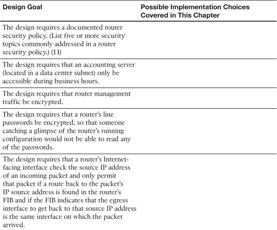
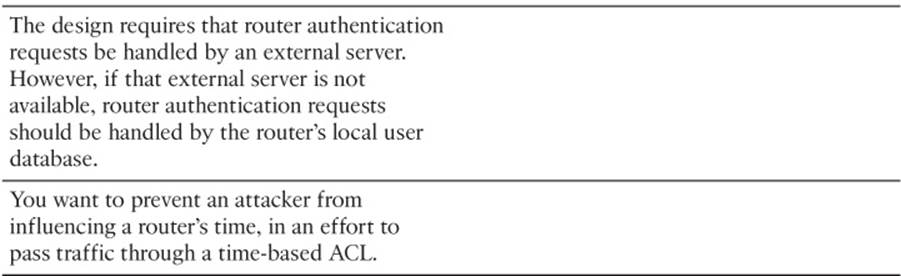
Table 16-7 Design Review
Implementation Plan Peer Review Table
Table 16-8 shows a list of questions that others might ask, or that you might think about, during a peer review of another network engineer’s implementation plan. Complete the table by answering the questions.
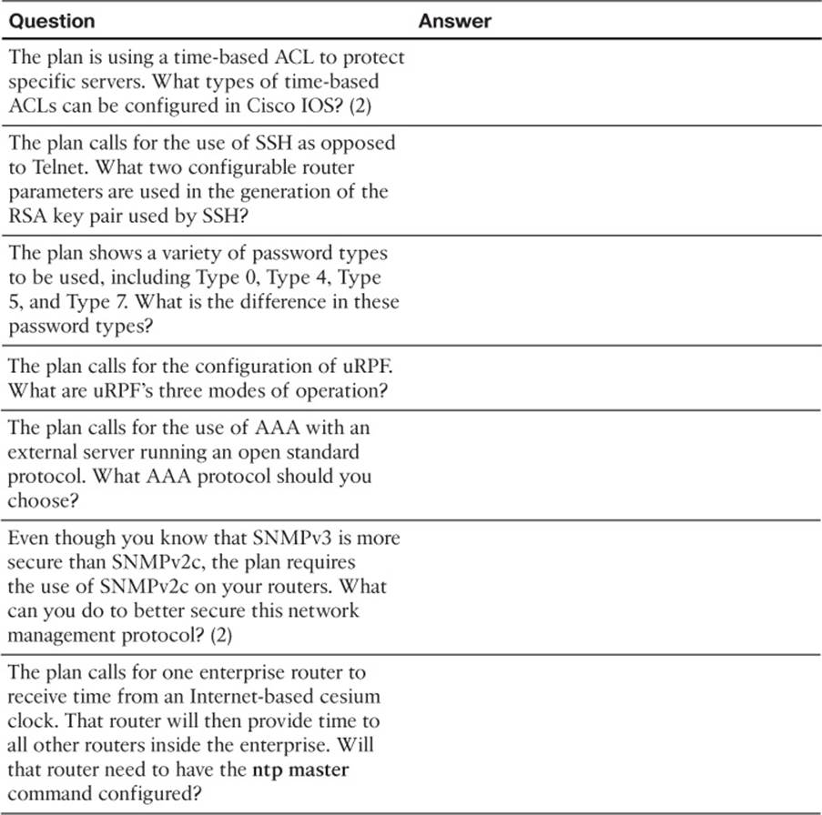
Table 16-8 Notable Questions from This Chapter to Consider During an Implementation Plan Peer Review
Create an Implementation Plan Table
To practice skills useful when creating your own OSPF implementation plan, list in Table 16-9 configuration commands related to the configuration of the following features. You might want to record your answers outside the book, and set a goal to complete this table (and others like it) from memory during your final reviews before taking the exam.
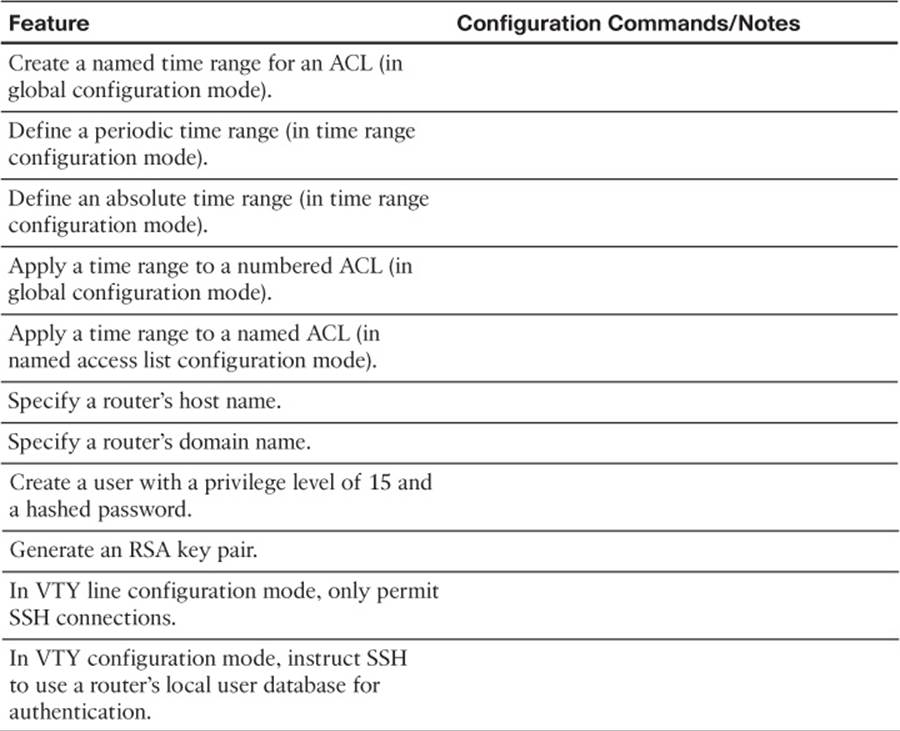
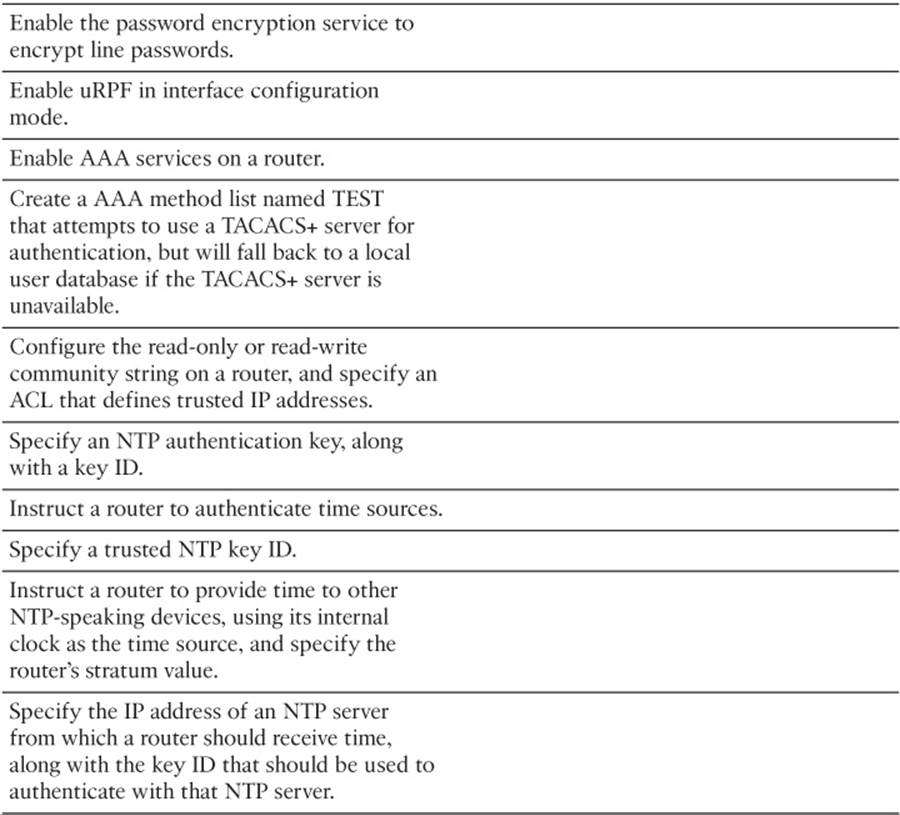
Table 16-9 Implementation Plan Configuration Memory Drill
Choose Commands for a Verification Plan Table
To practice skills useful when creating your own OSPF verification plan, list in Table 16-10 all commands that supply the requested information. You might want to record your answers outside the book, and set a goal to complete this table (and others like it) from memory during your final reviews before taking the exam.
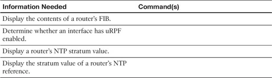
Table 16-10 Verification Plan Memory Drill
Review All the Key Topics
Review the most important topics from inside the chapter, noted with the Key Topic icon in the outer margin of the page. Table 16-11 lists a reference of these key topics and the page numbers on which each is found.
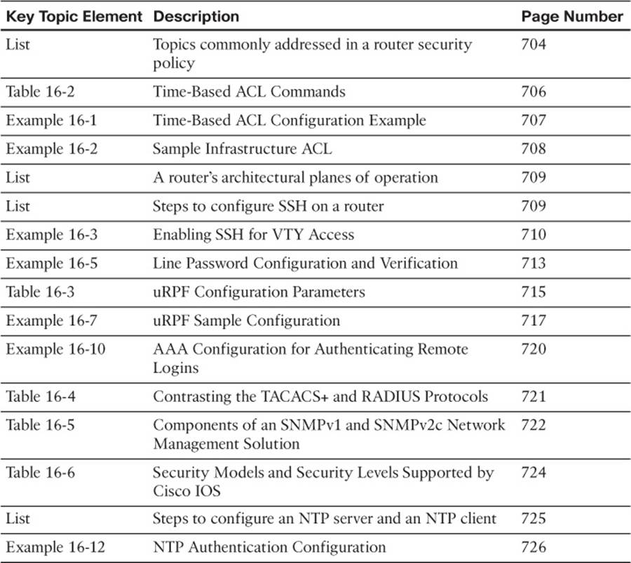
Table 16-11 Key Topics for Chapter 16
Complete the Tables and Lists from Memory
Print a copy of Appendix D, “Memory Tables,” (found on the CD) or at least the section for this chapter, and complete the tables and lists from memory. Appendix E, “Memory Tables Answer Key,” also on the CD, includes completed tables and lists to check your work.
Define Key Terms
Define the following key terms from this chapter, and check your answers in the glossary.
router security policy
time-based ACL
infrastructure ACL
NTP
uRPF
AAA
SNMP
All materials on the site are licensed Creative Commons Attribution-Sharealike 3.0 Unported CC BY-SA 3.0 & GNU Free Documentation License (GFDL)
If you are the copyright holder of any material contained on our site and intend to remove it, please contact our site administrator for approval.
© 2016-2026 All site design rights belong to S.Y.A.