CCNP Routing and Switching SWITCH 300-115 Official Cert Guide (2015)
Part I. Designing Campus Networks
Chapter 2. Switch Operation
This chapter covers the following topics that you need to master for the CCNP SWITCH exam:
![]() Layer 2 Switch Operation: This section describes the functionality of a switch that forwards Ethernet frames.
Layer 2 Switch Operation: This section describes the functionality of a switch that forwards Ethernet frames.
![]() Multilayer Switch Operation: This section describes the mechanisms that forward packets at OSI Layers 3 and 4.
Multilayer Switch Operation: This section describes the mechanisms that forward packets at OSI Layers 3 and 4.
![]() Tables Used in Switching: This section explains how tables of information and computation are used to make switching decisions. Coverage focuses on the content-addressable memory table involved in Layer 2 forwarding, and the ternary content-addressable memory used in packet-handling decisions at Layers 2 through 4.
Tables Used in Switching: This section explains how tables of information and computation are used to make switching decisions. Coverage focuses on the content-addressable memory table involved in Layer 2 forwarding, and the ternary content-addressable memory used in packet-handling decisions at Layers 2 through 4.
![]() Managing Switching Tables: This section reviews the Catalyst commands that you can use to configure and monitor the switching tables and memory. You will find these commands useful when troubleshooting or tracing the sources of data or problems in a switched network.
Managing Switching Tables: This section reviews the Catalyst commands that you can use to configure and monitor the switching tables and memory. You will find these commands useful when troubleshooting or tracing the sources of data or problems in a switched network.
To have a good understanding of the many features that you can configure on a Catalyst switch, you first should understand the fundamentals of the switching function.
This chapter serves as a primer, describing how an Ethernet switch works. It presents Layer 2 forwarding, along with the hardware functions that make forwarding possible. Multilayer switching is also explained. A considerable portion of the chapter deals with the memory architecture that performs switching at Layers 3 and 4 both flexibly and efficiently. This chapter also provides a brief overview of useful switching table management commands.
“Do I Know This Already?” Quiz
The “Do I Know This Already?” quiz allows you to assess whether you should read this entire chapter thoroughly or jump to the “Exam Preparation Tasks” section. If you are in doubt based on your answers to these questions or your own assessment of your knowledge of the topics, read the entire chapter. Table 2-1 outlines the major headings in this chapter and the “Do I Know This Already?” quiz questions that go with them. You can find the answers in Appendix A, “Answers to the ‘Do I Know This Already?’ Quizzes.”
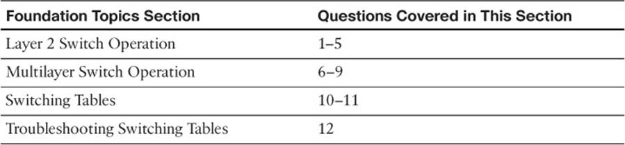
Table 2-1 “Do I Know This Already?” Foundation Topics Section-to-Question Mapping
1. Which of the following devices performs transparent bridging?
a. Ethernet hub
b. Layer 2 switch
c. Layer 3 switch
d. Router
2. When a PC is connected to a Layer 2 switch port, how far does the collision domain spread?
a. No collision domain exists.
b. One switch port.
c. One VLAN.
d. All ports on the switch.
3. What information is used to forward frames in a Layer 2 switch?
a. Source MAC address
b. Destination MAC address
c. Source switch port
d. IP addresses
4. What does a switch do if a MAC address cannot be found in the CAM table?
a. The frame is forwarded to the default port.
b. The switch generates an ARP request for the address.
c. The switch floods the frame out all ports (except the receiving port).
d. The switch drops the frame.
5. In a Catalyst switch, frames can be filtered with access lists for security and QoS purposes. This filtering occurs according to which of the following?
a. Before a CAM table lookup
b. After a CAM table lookup
c. Simultaneously with a CAM table lookup
d. According to how the access lists are configured
6. Access list contents can be merged into which of the following?
a. CAM table
b. TCAM table
c. FIB table
d. ARP table
7. Multilayer switches using CEF are based on which of these techniques?
a. Route caching
b. NetFlow switching
c. Topology-based switching
d. Demand-based switching
8. Which answer describes multilayer switching with CEF?
a. The first packet is routed and then the flow is cached.
b. The switch supervisor CPU forwards each packet.
c. The switching hardware learns station addresses and builds a routing database.
d. A single database of routing information is built for the switching hardware.
9. In a switch, frames are placed in which buffer after forwarding decisions are made?
a. Ingress queues
b. Egress queues
c. CAM table
d. TCAM
10. What size are the mask and pattern fields in a TCAM entry?
a. 64 bits
b. 128 bits
c. 134 bits
d. 168 bits
11. Access list rules are compiled as TCAM entries. When a packet is matched against an access list, in what order are the TCAM entries evaluated?
a. Sequentially in the order of the original access list.
b. Numerically by the access list number.
c. Alphabetically by the access list name.
d. All entries are evaluated in parallel.
12. Which Catalyst IOS command can you use to display the addresses in the CAM table?
a. show cam
b. show mac address-table
c. show mac
d. show cam address-table
Foundation Topics
Layer 2 Switch Operation
Consider a simple network that is built around many hosts that all share the same available bandwidth. This is known as a shared media network and was used in early legacy LANs made up of Ethernet hubs. The carrier sense multiple access collision detect (CSMA/CD) scheme determines when a device can transmit data on the shared LAN.

When more than one host tries to talk at one time, a collision occurs, and everyone must back off and wait to talk again. This forces every host to operate in half-duplex mode, by either talking or listening at any given time. In addition, when one host sends a frame, all connected hosts hear it. When one host generates a frame with errors, everyone hears that, too. This type of LAN is a collision domain because all device transmissions are susceptible to collisions.
An Ethernet switch operates at OSI Layer 2, making decisions about forwarding frames based on the destination MAC addresses found within the frames. This means that the Ethernet media is no longer shared among connected devices. Instead, at its most basic level, an Ethernet switch provides isolation between connected hosts in several ways:
![]() The collision domain’s scope is severely limited. On each switch port, the collision domain consists of the switch port itself and the devices directly connected to that port—either a single host or, if a shared-media hub is connected, the set of hosts connected to the hub.
The collision domain’s scope is severely limited. On each switch port, the collision domain consists of the switch port itself and the devices directly connected to that port—either a single host or, if a shared-media hub is connected, the set of hosts connected to the hub.
![]() Host connections can operate in full-duplex mode because there is no contention on the media. Hosts can talk and listen at the same time.
Host connections can operate in full-duplex mode because there is no contention on the media. Hosts can talk and listen at the same time.
![]() Bandwidth is no longer shared. Instead, each switch port offers dedicated bandwidth across a switching fabric to another switch port. (These frame forwarding paths change dynamically.)
Bandwidth is no longer shared. Instead, each switch port offers dedicated bandwidth across a switching fabric to another switch port. (These frame forwarding paths change dynamically.)
![]() Errors in frames are not propagated. Each frame received on a switch port is checked for errors. Good frames are regenerated when they are forwarded or transmitted. This is known as store-and-forward switching technology: Packets are received, stored for inspection, and then forwarded.
Errors in frames are not propagated. Each frame received on a switch port is checked for errors. Good frames are regenerated when they are forwarded or transmitted. This is known as store-and-forward switching technology: Packets are received, stored for inspection, and then forwarded.
![]() You can limit broadcast traffic to a volume threshold.
You can limit broadcast traffic to a volume threshold.
![]() Other types of intelligent filtering or forwarding become possible.
Other types of intelligent filtering or forwarding become possible.
Transparent Bridging
A Layer 2 switch is basically a multiport transparent bridge, where each switch port is its own Ethernet LAN segment, isolated from the others. Frame forwarding is based completely on the MAC addresses contained in each frame, such that the switch will not forward a frame unless it knows the destination’s location. (When the switch does not know where the destination is, it makes some safe assumptions.) Figure 2-1 shows the progression from a two-port to a multiport transparent bridge, and then to a Layer 2 switch.
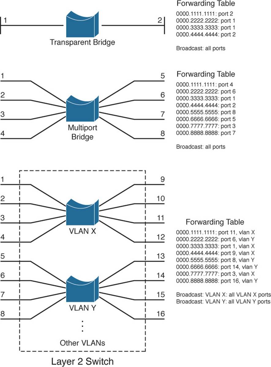
Figure 2-1 A Comparison of Transparent Bridges and Switches
The entire process of forwarding Ethernet frames then becomes figuring out what MAC addresses connect to which switch ports. For example, the Layer 2 switch in Figure 2-1 knows that the device using MAC address 0000.5555.5555 is located on switch port 8, which is assigned to VLAN Y. It also knows that frames arriving on VLAN Y and destined for the broadcast MAC address must be flooded out all ports that are assigned to VLAN Y.
A switch either must be told explicitly where hosts are located or must learn this information for itself. You can configure MAC address locations through a switch’s command-line interface, but this quickly gets cumbersome when there are many stations on the network or when stations move around from one switch port to another.
To dynamically learn about station locations, a switch listens to incoming frames and keeps a table of address information. In Figure 2-1, this information is kept in a forwarding table. As a frame is received on a switch port, the switch inspects the source MAC address. If that address is not in the address table already, the MAC address, switch port, and virtual LAN (VLAN) on which it arrived are recorded in the table. Learning the address locations of the incoming packets is easy and straightforward.
Incoming frames also include the destination MAC address. Again, the switch looks up this address in the address table, hoping to find the switch port and VLAN where the destination address is attached. If it is found, the frame can be forwarded out the corresponding switch port. If the address is not found in the table, the switch must take more drastic action: The frame is forwarded in a “best effort” fashion by flooding it out all switch ports assigned to the source VLAN. This is known as unknown unicast flooding, because the location of the unicast destination is unknown.
Figure 2-2 illustrates this process, using only a single VLAN for simplification. Suppose, for instance, that a packet arrives on switch port 3, containing destination MAC address 0000.aaaa.aaaa. The switch looks for that MAC address in its forwarding table, but is unable to find a matching entry. The switch then floods copies of the packet out every other port that is assigned to port 3’s VLAN, to increase the likelihood that 0000.aaaa.aaaa will eventually receive the packet that is destined for it. If the destination is the broadcast MAC address, the switch knows that the frame should be flooded out all ports on the VLAN.
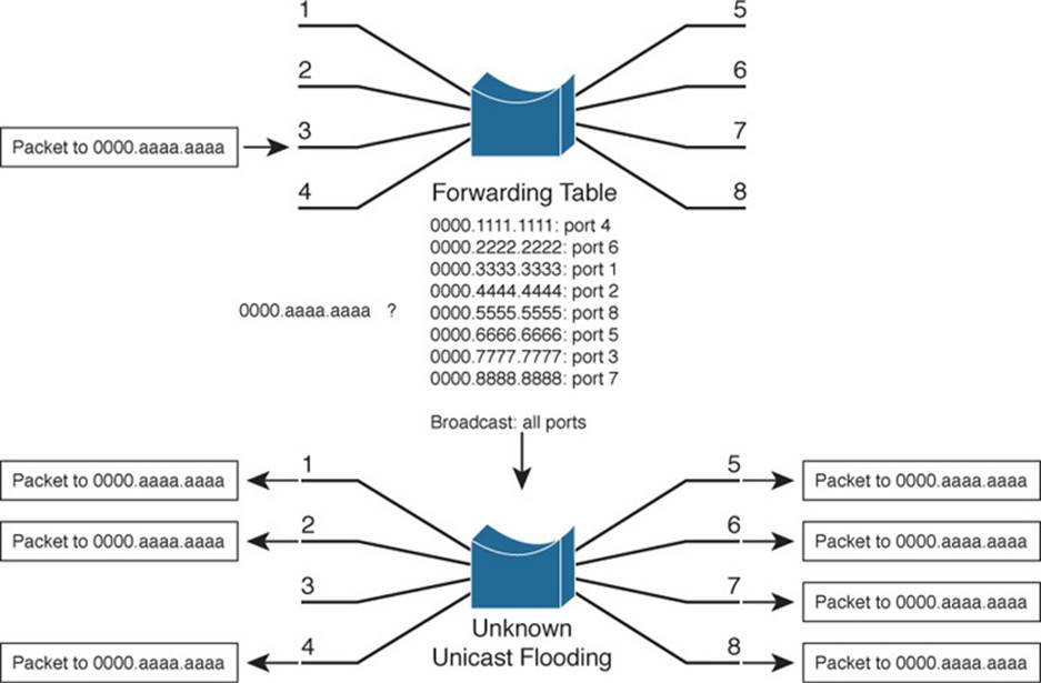
Figure 2-2 Unknown Unicast Flooding
A switch constantly listens to incoming frames on each of its ports, learning source MAC addresses. However, be aware that the learning process is allowed only when the Spanning Tree Protocol (STP) algorithm has decided that a port is stable for normal use. STP is concerned only with maintaining a loop-free network, where frames will not be forwarded recursively. If a loop formed, a flooded frame could follow the looped path, where it would be flooded again and again. STP is covered in greater detail in Chapters 6, “Traditional Spanning Tree Protocol,” through 9, “Advanced Spanning Tree Protocol.”
In a similar manner, frames containing a broadcast or multicast destination address are also flooded. These destination addresses are not unknown—the switch knows them well because they use standardized address values. For example, the Ethernet broadcast address is always ffff.ffff.ffff, IPv4 multicast addresses always begin with 01xx.xxxx.xxxx, and IPv6 multicast addresses begin with 3333.xxxx.xxxx. These addresses are destined for multiple locations, so they must be flooded by definition. In the case of multicast addresses, flooding is performed by default unless more specific recipient locations have been learned.
Follow That Frame!
You should have a basic understanding of the operations that a frame undergoes as it passes through a Layer 2 switch. This helps you get a firm grasp on how to configure the switch for complex functions. Figure 2-3 shows a typical Layer 2 Catalyst switch and the decision processes that take place to forward each frame.
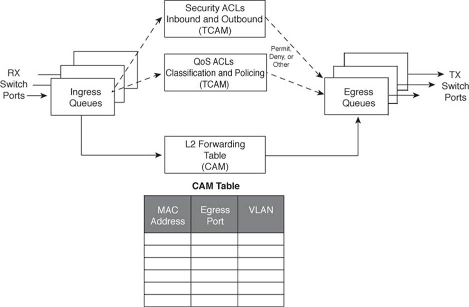
Figure 2-3 Operations Within a Layer 2 Catalyst Switch
When a frame arrives at a switch port, it is placed into one of the port’s ingress queues. The queues each can contain frames to be forwarded, with each queue having a different priority or service level. The switch port then can be fine-tuned so that important frames get processed and forwarded before less-important frames. This can prevent time-critical data from being “lost in the shuffle” during a flurry of incoming traffic.
As the ingress queues are serviced and a frame is pulled off, the switch must figure out not only where to forward the frame, but also whether it should be forwarded and how. Three fundamental decisions must be made: one concerned with finding the egress switch port, and two concerned with forwarding policies. All these decisions are made simultaneously by independent portions of switching hardware and can be described as follows:
![]() L2 forwarding table: The frame’s destination MAC address is used as an index, or key, into the content-addressable memory (CAM), or address, table. If the address is found, the egress switch port and the appropriate VLAN ID are read from the table. (If the address is not found, the frame is marked for flooding so that it is forwarded out every switch port in the VLAN.)
L2 forwarding table: The frame’s destination MAC address is used as an index, or key, into the content-addressable memory (CAM), or address, table. If the address is found, the egress switch port and the appropriate VLAN ID are read from the table. (If the address is not found, the frame is marked for flooding so that it is forwarded out every switch port in the VLAN.)
![]() Security ACLs: Access control lists (ACLs) can be used to identify frames according to their MAC addresses, protocol types (for non-IP frames), IP addresses, protocols, and Layer 4 port numbers. The ternary content-addressable memory (TCAM) contains ACLs in a compiled form so that a decision can be made on whether to forward a frame in a single table lookup.
Security ACLs: Access control lists (ACLs) can be used to identify frames according to their MAC addresses, protocol types (for non-IP frames), IP addresses, protocols, and Layer 4 port numbers. The ternary content-addressable memory (TCAM) contains ACLs in a compiled form so that a decision can be made on whether to forward a frame in a single table lookup.
![]() QoS ACLs: Other ACLs can classify incoming frames according to quality of service (QoS) parameters, to police or control the rate of traffic flows, and to mark QoS parameters in outbound frames. The TCAM is also used to make these decisions in a single table lookup.
QoS ACLs: Other ACLs can classify incoming frames according to quality of service (QoS) parameters, to police or control the rate of traffic flows, and to mark QoS parameters in outbound frames. The TCAM is also used to make these decisions in a single table lookup.
The CAM and TCAM tables are discussed in greater detail in the “Content-Addressable Memory” and “Ternary Content-Addressable Memory” sections, later in this chapter. After the CAM and TCAM table lookups have occurred, the frame is placed into the appropriate egress queue on the appropriate outbound switch port. The egress queue is determined by QoS values either contained in the frame or passed along with the frame. Like the ingress queues, the egress queues are serviced according to importance or time criticality; higher priority frames are sent out without being delayed by other outbound traffic.
Multilayer Switch Operation
Many Cisco Catalyst switches can also forward frames based on Layers 3 and 4 information contained in packets. This is known as multilayer switching (MLS). Naturally, Layer 2 switching is performed at the same time because even the higher-layer encapsulations still are contained in Ethernet frames.
Types of Multilayer Switching
Catalyst switches have supported two basic generations or types of MLS: route caching (first-generation MLS) and topology based (second-generation MLS). This section presents an overview of both, although only the second generation is supported in the Cisco IOS Software-based switch families, such as the Catalyst 2960, 3750, 4500, and 6500. You should understand the two types and the differences between them:
![]() Route caching: The first generation of MLS, requiring a route processor (RP) and a switch engine (SE). The RP must process a traffic flow’s first packet to determine the destination. The SE listens to the first packet and to the resulting destination, and then sets up a “shortcut” entry in its MLS cache. The SE forwards subsequent packets belonging to the same traffic flow based on shortcut entries in its cache.
Route caching: The first generation of MLS, requiring a route processor (RP) and a switch engine (SE). The RP must process a traffic flow’s first packet to determine the destination. The SE listens to the first packet and to the resulting destination, and then sets up a “shortcut” entry in its MLS cache. The SE forwards subsequent packets belonging to the same traffic flow based on shortcut entries in its cache.
This type of MLS also is known by the names NetFlow LAN switching, flow-based or demand-based switching, and route once, switch many. The RP must examine each new traffic flow and set up shortcut entries for the SE. Even if this method isn’t used to forward packets in Cisco IOS–based Catalyst switches, the technique can still be used to generate traffic flow information and statistics.
![]() Topology based: The second generation of MLS, utilizing specialized hardware, is also organized with distinct RP and SE functions. The RP uses Layer 3 routing information to build and prepopulate a single database of the entire known network topology. This database becomes an efficient table lookup in hardware, and is consulted so that packets can be forwarded at high rates by the SE. The longest match found in the database is used as the correct Layer 3 destination. As the routing topology changes over time, the database contained in the hardware can be updated dynamically with no performance penalty.
Topology based: The second generation of MLS, utilizing specialized hardware, is also organized with distinct RP and SE functions. The RP uses Layer 3 routing information to build and prepopulate a single database of the entire known network topology. This database becomes an efficient table lookup in hardware, and is consulted so that packets can be forwarded at high rates by the SE. The longest match found in the database is used as the correct Layer 3 destination. As the routing topology changes over time, the database contained in the hardware can be updated dynamically with no performance penalty.
This type of MLS is known as Cisco Express Forwarding (CEF). A routing process running on the switch downloads the current routing table database into the Forwarding Information Base (FIB) area of hardware. CEF is discussed in greater detail in Chapter 11, “Multilayer Switching.”
Tip
Although the RP and SE functions within a multilayer switch do interact, they can operate independently, as if they are on different “planes.” The control plane of a switch includes the RP and any process that runs to control or manage the switch, whereas the data plane exists in the SE, where data is forwarded.
Follow That Packet!
The path that a Layer 3 packet follows through a multilayer switch is similar to that of a Layer 2 switch. Obviously, some means of making a Layer 3 forwarding decision must be added. Beyond that, several, sometimes unexpected, things can happen to packets as they are forwarded. Figure 2-4 shows a typical multilayer switch and the decision processes that must occur. Packets arriving on a switch port are placed in the appropriate ingress queue, just as in a Layer 2 switch.
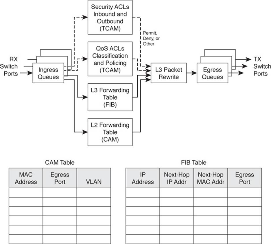
Figure 2-4 Operations Within a Multilayer Catalyst Switch
Each packet is pulled off an ingress queue and inspected for both Layer 2 and Layer 3 destination addresses. Now, the decision of where to forward the packet is based on two address tables, whereas the decision of how to forward the packet still is based on access list results.
All the multilayer switching decisions are performed simultaneously in hardware, using the following functions:
![]() L2 forwarding table: The destination MAC address is used as an index into the CAM table. If the frame contains a Layer 3 packet that needs to be forwarded from one subnet to another, the destination MAC address will contain the address of a Layer 3 port on the switch itself. In this case, the CAM table results are used only to decide that the frame should be processed at Layer 3.
L2 forwarding table: The destination MAC address is used as an index into the CAM table. If the frame contains a Layer 3 packet that needs to be forwarded from one subnet to another, the destination MAC address will contain the address of a Layer 3 port on the switch itself. In this case, the CAM table results are used only to decide that the frame should be processed at Layer 3.
![]() L3 forwarding table: The FIB table is consulted, using the destination IP address as an index. The longest match in the table is found (both address and mask), and the resulting next-hop Layer 3 address is obtained. The FIB also contains each next-hop router’s Layer 2 MAC address and the egress switch port (and VLAN ID) so that further table lookups are not necessary.
L3 forwarding table: The FIB table is consulted, using the destination IP address as an index. The longest match in the table is found (both address and mask), and the resulting next-hop Layer 3 address is obtained. The FIB also contains each next-hop router’s Layer 2 MAC address and the egress switch port (and VLAN ID) so that further table lookups are not necessary.
![]() Security ACLs: Inbound and outbound access lists are compiled into TCAM entries so that decisions of whether to forward a packet can be determined as a single table lookup.
Security ACLs: Inbound and outbound access lists are compiled into TCAM entries so that decisions of whether to forward a packet can be determined as a single table lookup.
![]() QoS ACLs: Packet classification, policing, and marking all can be performed as single table lookups in the QoS TCAM.
QoS ACLs: Packet classification, policing, and marking all can be performed as single table lookups in the QoS TCAM.
As with Layer 2 switching, the packet finally must be placed in the appropriate egress queue on the appropriate egress switch port.
During the multilayer switching process, some portions of the frame must be modified or rewritten, just as any router would do. For example, the destination MAC address in the inbound frame contains the address of the next-hop destination, which is the ingress Layer 3 interface on the multilayer switch. Once the FIB table is consulted, the next-hop router IP and MAC addresses are found.
The next-hop Layer 2 address must be put into the frame in place of the original destination address (the multilayer switch). The frame’s Layer 2 source address also must become that of the multilayer switch’s egress interface before the frame is sent on to the next hop. As any good router must do, the time-to-live (TTL) value in the Layer 3 packet must be decremented by one.
Because the contents of the Layer 3 packet (the TTL value) have changed, the Layer 3 header checksum must be recalculated. And because both Layers 2 and 3 contents have changed, the Layer 2 checksum must be recalculated. In other words, the entire Ethernet frame must be rewritten before it goes into the egress queue. This also is accomplished efficiently in hardware.
Multilayer Switching Exceptions
To forward packets using the simultaneous decision processes described in the preceding section, the packet must be “MLS ready” and must require no additional decisions. For example, CEF can directly forward most IP and IPv6 packets between hosts. This occurs when the source and destination addresses (both MAC and IP) are already known and no other IP parameters must be manipulated.
Other packets cannot be directly forwarded by CEF and must be handled in more detail. This is done by a quick inspection during the forwarding decisions. If a packet meets criteria such as the following, it is flagged for further processing and sent or “punted” to the switch CPU for process switching:
![]() ARP requests and replies
ARP requests and replies
![]() IP packets requiring a response from a router (TTL has expired, maximum transmission unit [MTU] is exceeded, fragmentation is needed, and so on)
IP packets requiring a response from a router (TTL has expired, maximum transmission unit [MTU] is exceeded, fragmentation is needed, and so on)
![]() IP broadcasts that will be relayed as unicast (Dynamic Host Configuration Protocol [DHCP] requests, IP helper-address functions)
IP broadcasts that will be relayed as unicast (Dynamic Host Configuration Protocol [DHCP] requests, IP helper-address functions)
![]() Routing protocol updates
Routing protocol updates
![]() Cisco Discovery Protocol (CDP) packets
Cisco Discovery Protocol (CDP) packets
![]() Packets needing encryption
Packets needing encryption
![]() Packets triggering Network Address Translation (NAT)
Packets triggering Network Address Translation (NAT)
![]() Legacy multiprotocol packets (IPX, AppleTalk, and so on)
Legacy multiprotocol packets (IPX, AppleTalk, and so on)
As you might expect, packets that are punted to the CPU cannot be forwarded as efficiently as ones that can be forwarded in hardware directly. The additional processing takes additional time and consumes CPU resources. Ideally, all packets should be forwarded in hardware, but that is not always possible.
Tables Used in Switching
Catalyst switches maintain several types of tables to be used in the switching process. The tables are tailored for Layer 2 switching or MLS and are kept in very fast memory so that many fields within a frame or packet can be compared in parallel.
Content-Addressable Memory
All Catalyst switch models use a CAM table for Layer 2 switching. As frames arrive on switch ports, the source MAC addresses are learned and recorded in the CAM table. The port of arrival and the VLAN both are recorded in the table, along with a time stamp. If a MAC address learned on one switch port has moved to a different port, the MAC address and time stamp are recorded for the most recent arrival port. Then, the previous entry is deleted. If a MAC address is found already present in the table for the correct arrival port, only its time stamp is updated.
Switches generally have large CAM tables so that many addresses can be looked up for frame forwarding. However, there is not enough table space to hold every possible address on large networks. To manage the CAM table space, stale entries (addresses that have not been heard from for a period of time) are aged out. By default, idle CAM table entries are kept for 300 seconds before they are deleted. You can change the default setting using the following configuration command:
Switch(config)# mac address-table aging-time seconds
By default, MAC addresses are learned dynamically from incoming frames. You also can configure static CAM table entries that contain MAC addresses that might not be learned otherwise. To do this, use the following configuration command:
Switch(config)# mac address-table static mac-address vlan vlan-id interface type
mod/num
Note
You should be aware that there is a slight discrepancy in the CAM table command syntax. Until Catalyst IOS version 12.1(11)EA1, the syntax for CAM table commands used the keywords mac-address-table. In more recent Cisco IOS versions, the syntax has changed to use the keywords mac address-table (first hyphen omitted). The Catalyst 4500 and 6500 IOS Software are exceptions, however, and continue to use the mac-address-table keyword form. Many switch platforms support either syntax to ease the transition.
Exactly what happens when a host’s MAC address is learned on one switch port, and then the host moves so that it appears on a different switch port? Ordinarily, the host’s original CAM table entry would have to age out after 300 seconds, while its address was learned on the new port. To avoid having duplicate CAM table entries during that time, a switch purges any existing entries for a MAC address that has just been learned on a different switch port. This is a safe assumption because MAC addresses are unique, and a single host should never be seen on more than one switch port unless problems exist in the network. If a switch notices that a MAC address is being learned on alternating switch ports, it generates an error message that flags the MAC address as “flapping” between interfaces.
Ternary Content-Addressable Memory
In traditional routing, ACLs can match, filter, or control specific traffic. Access lists are made up of one or more access control entities (ACEs) or matching statements that are evaluated in sequential order. Evaluating an access list can take up additional time, adding to the latency of forwarding packets.
In multilayer switches, however, all the matching process that ACLs provide is implemented in hardware called a TCAM. With a TCAM, a packet can be evaluated against an entire access list within a single table lookup. Most switches have multiple TCAMs so that both inbound and outbound security and QoS ACLs can be evaluated simultaneously, or entirely in parallel with a Layer 2 or Layer 3 forwarding decision.
The Catalyst IOS Software has two components that are part of the TCAM operation:
![]() Feature Manager (FM): After an access list has been created or configured, the Feature Manager software compiles, or merges, the ACEs into entries in the TCAM table. The TCAM then can be consulted at full frame-forwarding speed.
Feature Manager (FM): After an access list has been created or configured, the Feature Manager software compiles, or merges, the ACEs into entries in the TCAM table. The TCAM then can be consulted at full frame-forwarding speed.
![]() Switching Database Manager (SDM): On some Catalyst switch models, the TCAM is partitioned into several areas that support different functions. The SDM software configures or tunes the TCAM partitions, if needed, to provide ample space for specific switching functions. (The TCAM is fixed on Catalyst 4500 and 6500 platforms and cannot be repartitioned.)
Switching Database Manager (SDM): On some Catalyst switch models, the TCAM is partitioned into several areas that support different functions. The SDM software configures or tunes the TCAM partitions, if needed, to provide ample space for specific switching functions. (The TCAM is fixed on Catalyst 4500 and 6500 platforms and cannot be repartitioned.)
TCAM Structure
The TCAM is an extension of the CAM table concept. Recall that a CAM table takes in an index or key value (usually a MAC address) and looks up the resulting value (usually a switch port or VLAN ID). Table lookup is fast and always based on an exact key match consisting of binary numbers made up of two possible values: 0 and 1 bits.
TCAM also uses a table-lookup operation but is greatly enhanced to allow a more abstract operation. For example, binary values (0s and 1s) make up a key into the table, but a mask value also is used to decide which bits of the key are actually relevant. This effectively makes a key consisting of three input values: 0, 1, and X (do not care) bit values—a threefold or ternary combination.
TCAM entries are composed of Value, Mask, and Result (VMR) combinations. Fields from frame or packet headers are fed into the TCAM, where they are matched against the value and mask pairs to yield a result. As a quick reference, these can be described as follows:
![]() Values are always 134-bit quantities, consisting of source and destination addresses and other relevant protocol information—all patterns to be matched. The information concatenated to form the value depends on the type of access list, as shown in Table 2-2. Values in the TCAM come directly from any address, port, or other protocol information given in an ACE, up to a maximum of 134 bits.
Values are always 134-bit quantities, consisting of source and destination addresses and other relevant protocol information—all patterns to be matched. The information concatenated to form the value depends on the type of access list, as shown in Table 2-2. Values in the TCAM come directly from any address, port, or other protocol information given in an ACE, up to a maximum of 134 bits.
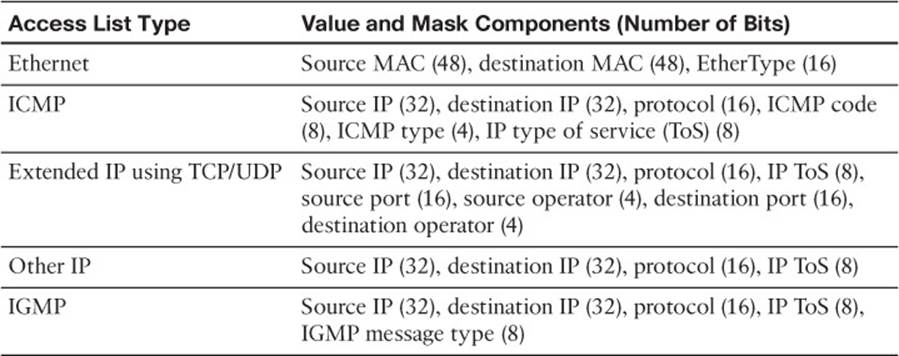
Table 2-2 TCAM Value Pattern Components
![]() Masks are also 134-bit quantities, in exactly the same format, or bit order, as the values. Masks select only the value bits of interest; a mask bit is set to mark a value bit to be exactly matched or is not set to mark a value bit that does not matter. The masks used in the TCAM stem from address or bit masks in ACEs.
Masks are also 134-bit quantities, in exactly the same format, or bit order, as the values. Masks select only the value bits of interest; a mask bit is set to mark a value bit to be exactly matched or is not set to mark a value bit that does not matter. The masks used in the TCAM stem from address or bit masks in ACEs.
![]() Results are numeric values that represent what action to take after the TCAM lookup occurs. Whereas traditional access lists offer only a permit or deny result, TCAM lookups offer a number of possible results or actions. For example, the result can be a permit or deny decision, an index value to a QoS policer, a pointer to a next-hop routing table, and so on.
Results are numeric values that represent what action to take after the TCAM lookup occurs. Whereas traditional access lists offer only a permit or deny result, TCAM lookups offer a number of possible results or actions. For example, the result can be a permit or deny decision, an index value to a QoS policer, a pointer to a next-hop routing table, and so on.
Note
This section discusses TCAM from an IPv4 perspective. When a dual IPv4-IPv6 SDM template is used, the TCAM becomes more limited in size. Because IPv6 addresses are 128 bits in length, some address compression must be used to store them in TCAM entries.
The TCAM is always organized by masks, where each unique mask has eight value patterns associated with it. For example, the Catalyst 6500 TCAM (one for security ACLs and one for QoS ACLs) holds up to 4096 masks and 32,768 value patterns. The trick is that each of the mask-value pairs is evaluated simultaneously, or in parallel, revealing the best or longest match in a single table lookup.
TCAM Example
Figure 2-5 shows how the TCAM is built and used. This is a simple example and might or might not be identical to the results that the Feature Manager produces because the ACEs might need to be optimized or rewritten to achieve certain TCAM algorithm requirements.
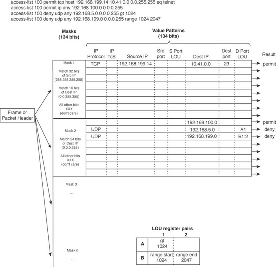
Figure 2-5 How an Access List Is Merged into TCAM
The sample access list 100 (extended IP) is configured and merged into TCAM entries. First, the mask values must be identified in the access list. When an address value and a corresponding address mask are specified in an ACE, those mask bits must be set for matching. All other mask bits can remain in the “do not care” state because they will not be used.
The access list contains only three unique masks: one that matches all 32 bits of the source IP address (found with an address mask of 0.0.0.0 or the keyword host), one that matches 16 bits of the destination address (found with an address mask of 0.0.255.255), and one that matches only 24 bits of the destination address (found with an address mask of 0.0.0.255). The keyword any in the ACEs means “match anything” or “do not care.”
The three unique masks are placed into the TCAM. Then, for each mask, all possible value patterns are identified. For example, a 32-bit source IP mask (Mask 1) can be found only in ACEs with a source IP address of 192.168.199.14 and a destination of 10.41.0.0. (The rest of Mask 1 is the destination address mask 0.0.255.255.) Those address values are placed into the first value pattern slot associated with Mask 1. Mask 2 (0.0.255.255) has three value patterns: destination addresses 192.168.100.0, 192.168.5.0, and 192.168.199.0. Each of these is placed in the three pattern positions of Mask 2. This process continues until all ACEs have been merged.
When a mask’s eighth pattern position has been filled, the next pattern with the same mask must be placed under a new mask in the table. A bit of a balancing act occurs to try to fit all ACEs into the available mask and pattern entries without an overflow.
Port Operations in TCAM
You might have noticed that matching strictly based on values and masks covers only ACE statements that involve exact matches (either the eq port operation keyword or no Layer 4 port operations). For example, ACEs such as the following involve specific address values, address masks, and port numbers:
access-list test permit ip 192.168.254.0 0.0.0.255 any
access-list test permit tcp any host 192.168.199.10 eq www
What about ACEs that use port operators, where a comparison must be made? Consider the following:
access-list test permit udp any host 192.168.199.50 gt 1024
access-list test permit tcp any any range 2000 2002
A simple logical operation between a mask and a pattern cannot generate the desired result. The TCAM also provides a mechanism for performing a Layer 4 operation or comparison, also done during the single table lookup. If an ACE has a port operator, such as gt, lt, neq, or range, the Feature Manager software compiles the TCAM entry to include the use of the operator and the operand in a logical operation unit (LOU) register. Only a limited number of LOUs are available in the TCAM. If there are more ACEs with comparison operators than there are LOUs, the Feature Manager must break up the ACEs into multiple ACEs with only regular matching (using the eq operator).
In Figure 2-5, two ACEs require a Layer 4 operation:
![]() One that checks for UDP destination ports greater than 1024
One that checks for UDP destination ports greater than 1024
![]() One that looks for the UDP destination port range 1024 to 2047
One that looks for the UDP destination port range 1024 to 2047
The Feature Manager checks all ACEs for Layer 4 operation and places these into LOU register pairs. These can be loaded with operations, independent of any other ACE parameters. The LOU contents can be reused if other ACEs need the same comparisons and values. After the LOUs are loaded, they are referenced in the TCAM entries that need them. This is shown by LOUs A1 and the B1:2 pair. A finite number (actually, a rather small number) of LOUs are available in the TCAM, so the Feature Manager software must use them carefully.
Managing Switching Tables
You can display or query the switching tables to verify the information that the switch has learned. As well, you might want to check the tables to find out on which switch port a specific MAC address has been learned. You can also manage the size of the various switching tables to optimize performance.
CAM Table Operation
To view the contents of the CAM table, you can use the following form of the show mac address-table EXEC command:
Switch# show mac address-table dynamic [address mac-address | interface type
mod/num | vlan vlan-id]
The entries that have been learned dynamically will be shown. You can add the address keyword to specify a single MAC address, or the interface or vlan keyword to see addresses that have been learned on a specific interface or VLAN.
For example, assume that you need to find the learned location of the host with MAC address 0050.8b11.54da. The show mac address-table dynamic address 0050.8b11.54da command might produce the output in Example 2-1.
Example 2-1 Determining Host Location by MAC Address
Switch# show mac address-table dynamic address 0050.8b11.54da
Mac Address Table
--------------------------------------------
Vlan Mac Address Type Ports
---- ----------- ---- -----
54 0050.8b11.54da DYNAMIC Gi1/0/1
Total Mac Addresses for this criterion: 1
Switch#
From this output, you can see that the host is somehow connected to interface Gigabit Ethernet 1/0/1, on VLAN 54.
Tip
If your Catalyst IOS switch is not accepting commands of the form mac address-table, try adding a hyphen between the keywords. For example, the Catalyst 4500 and 6500 most likely will accept show mac-address-table instead.
Suppose that this same command produced no output, showing nothing about the interface and VLAN where the MAC address is found. What might that mean? Either the host has not sent a frame that the switch can use for learning its location, or something odd is going on. Perhaps the host is using two network interface cards (NICs) to load balance traffic; one NIC is only receiving traffic, whereas the other is only sending. Therefore, the switch never hears and learns the receiving-only NIC address.
To see all the MAC addresses that are currently found on interface Gigabit Ethernet 1/0/29, you could use the show mac address-table dynamic interface gig1/0/29 command. The output shown in Example 2-2 indicates that only one host has been learned on the interface. Perhaps only a single PC connects to that interface.
Example 2-2 Determining Hosts Active on an Interface
Switch# show mac address-table dynamic interface gigabitethernet1/0/29
Mac Address Table
-----------------------------------------------
Vlan Mac Address Type Ports
---- ----------- ---- -----
537 0013.7297.3d4b DYNAMIC Gi1/0/29
Total Mac Addresses for this criterion: 1
Switch#
However, suppose the same command is used to check interface Gigabit Ethernet 1/1/1. The output shown in Example 2-3 lists many MAC addresses—all found on a single interface. How can so many addresses be learned on one switch interface? This interface must lead to another switch or another part of the network where other devices are located. As frames have been received on Gigabit Ethernet 1/1/1, coming from the other devices, the local switch has added the source MAC addresses into its CAM table.
Example 2-3 Finding Many Hosts on an Interface
Switch# show mac address-table dynamic interface gig1/1/1
Mac Address Table
------------------------------------------------
Vlan Mac Address Type Ports
---- ----------- ---- -----
580 0000.0c07.ac01 DYNAMIC Gi1/1/1
580 0007.0e0b.f918 DYNAMIC Gi1/1/1
580 000f.1f78.1094 DYNAMIC Gi1/1/1
580 0011.43ac.b083 DYNAMIC Gi1/1/1
580 0011.bb2d.3f6e DYNAMIC Gi1/1/1
580 0014.6a86.1f1e DYNAMIC Gi1/1/1
580 0014.6a86.1f3d DYNAMIC Gi1/1/1
580 0014.6a86.1f3f DYNAMIC Gi1/1/1
580 0014.6a86.1f47 DYNAMIC Gi1/1/1
—More—
Tip
Often, you need to know where a user with a certain MAC address is connected. In a large network, discerning at which switch and switch port a MAC address can be found might be difficult. Start at the network’s center, or core, and display the CAM table entry for the user’s MAC address. Look at the switch port shown in the entry and find the neighboring switch connected to that port using CDP neighbor information. Then move to that switch and repeat the CAM table query process. Keep moving from switch to switch until you reach the edge of the network where the MAC address physically connects.
To see the CAM table’s size, use the show mac address-table count command, as shown in Example 2-4. MAC address totals are shown for each active VLAN on the switch, as well as the total number of spaces remaining in the CAM table. This can give you a good idea of the size of the CAM table and how many hosts are using the network.
Example 2-4 Checking the Size of the CAM Table
Switch# show mac address-table count
Mac Entries for Vlan 1:
---------------------------
Dynamic Address Count : 0
Static Address Count : 0
Total Mac Addresses : 0
Mac Entries for Vlan 2:
----------------------------
Dynamic Address Count : 89
Static Address Count : 0
Total Mac Addresses : 89
Mac Entries for Vlan 580:
-----------------------------
Dynamic Address Count : 244
Static Address Count : 0
Total Mac Addresses : 244
Total Mac Address Space Available: 5791
Switch#
CAM table entries can be cleared manually, if needed, by using the following EXEC command:
Switch# clear mac address-table dynamic [address mac-address | interface type
mod/num | vlan vlan-id]
TCAM Operation
The TCAM in a switch is more or less self-sufficient. Access lists are compiled or merged automatically into the TCAM, so there is nothing to configure. The only concept you need to be aware of is how the TCAM resources are being used. You can use the show platform tcam utilizationEXEC command shown in Example 2-5 to get an idea of the TCAM utilization. Compare the Used number of entries to the Max value.
Example 2-5 Displaying TCAM Utilization
Switch# show platform tcam utilization
CAM Utilization for ASIC# 0 Max Used
Masks/Values Masks/Values
Unicast mac addresses: 6364/6364 311/311
IPv4 IGMP groups + multicast routes: 1120/1120 8/8
IPv4 unicast directly-connected routes: 6144/6144 0/0
IPv4 unicast indirectly-connected routes: 2048/2048 28/28
IPv4 policy based routing aces: 452/452 12/12
IPv4 qos aces: 512/512 21/21
IPv4 security aces: 964/964 33/33
Note: Allocation of TCAM entries per feature uses
a complex algorithm. The above information is meant
to provide an abstract view of the current TCAM utilization
Switch#
TCAMs have a limited number of usable mask, value pattern, and LOU entries. If access lists grow to be large or many Layer 4 operations are needed, the TCAM tables and registers can overflow. If that happens while you are configuring an ACL, the switch will generate syslog messages that flag the TCAM overflow situation as it tries to compile the ACL into TCAM entries.
Managing Switching Table Sizes
High-end Cisco switches are designed for efficient multilayer switching at any location within a network. For example, the versatile Catalyst 4500 and 6500 models can be used equally well in the core, distribution, or access layer because their hardware contains ample switching engines and table space for any application. Other models, such as the 2960, 3750, and 3850, have a fixed architecture with limited switching table space. The CAM, FIB, and other tables must all share resources; for one table to grow larger, the others must grow smaller.
Fortunately, you can select a preferred type of switching that, in turn, affects the relative size of the switching tables. To excel at Layer 2 switching, the CAM table should increase in size, whereas the FIB or routing table space should decrease. If a switch is used to route traffic, its FIB table space should grow and its CAM table should shrink.
The SDM manages the memory partitions in a switch. You can display the current partition preference and a breakdown of table sizes with the following EXEC command:
Switch# show sdm prefer
Example 2-6 shows that the switch is operating with the “desktop default” memory template, which is tailored for the access layer. According to the numbers, the desktop default template provides a balanced mix of Layer 2 (unicast MAC addresses, or the CAM table) and Layer 3 (IPv4 unicast routes, or the FIB table), in addition to IPv4 ACLs, and some minimal support for IPv6.
Example 2-6 Displaying the Current SDM Template
Switch# show sdm prefer
The current template is "desktop default" template.
The selected template optimizes the resources in
the switch to support this level of features for
8 routed interfaces and 1024 VLANs.
number of unicast mac addresses: 6K
number of IPv4 IGMP groups + multicast routes: 1K
number of IPv4 unicast routes: 8K
number of directly-connected IPv4 hosts: 6K
number of indirect IPv4 routes: 2K
number of IPv6 multicast groups: 64
number of directly-connected IPv6 addresses: 74
number of indirect IPv6 unicast routes: 32
number of IPv4 policy based routing aces: 0
number of IPv4/MAC qos aces: 0.5K
number of IPv4/MAC security aces: 0.875k
number of IPv6 policy based routing aces: 0
number of IPv6 qos aces: 0
number of IPv6 security aces: 60
Switch#
You can configure a switch to operate based on other SDM templates by using the following global configuration command:
Switch(config)# sdm prefer template
The switch must then be rebooted for the new template to take effect. Tables 2-3 and 2-4 list the template types along with the number of entries allowed in each memory partition. The two shaded rows represent the CAM and FIB table spaces. To get a feel for the SDM templates, notice which function is favored in each of the template types. The unicast MAC addresses and unicast routes rows are highlighted as examples.
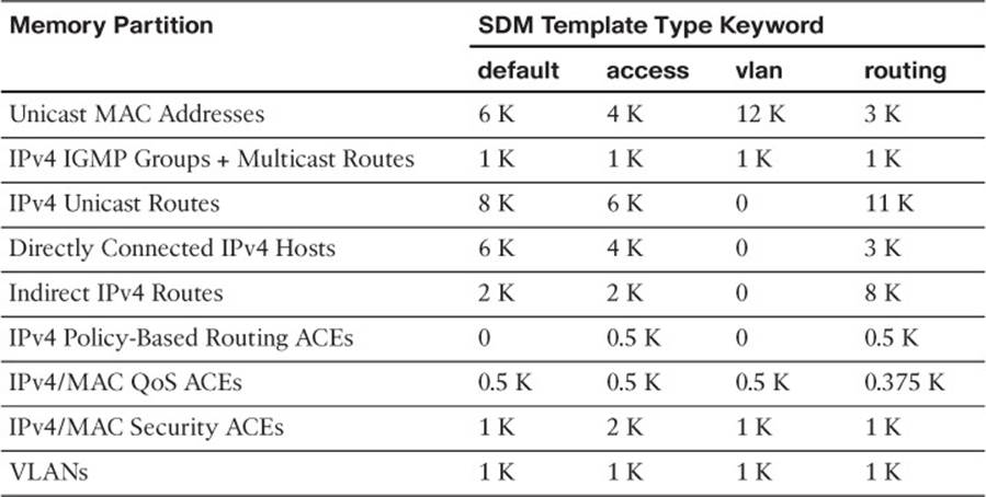
Table 2-3 IPv4 SDM Templates and Memory Partitions
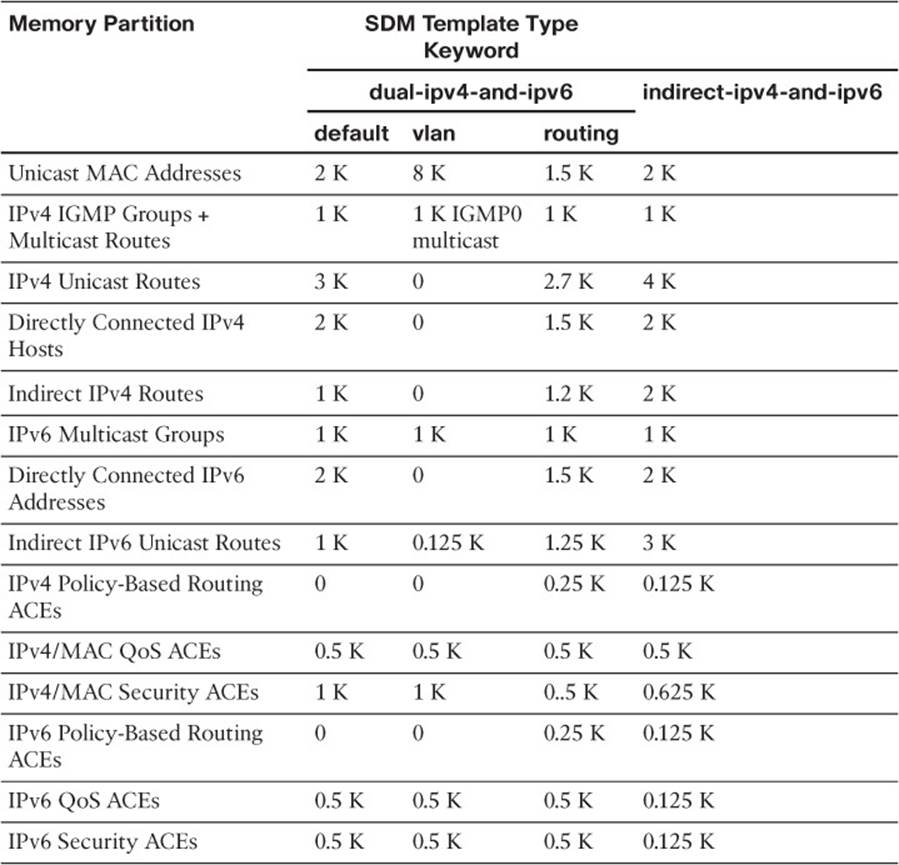
Table 2-4 Dual IPv4-IPv6 SDM Templates and Memory Partitions
Do not worry about memorizing the tables and their contents; instead, you should know how to display the current template and how to configure a new one.
Exam Preparation Tasks
Review All Key Topics
Review the most important topics in the chapter, noted with the Key Topic icon in the outer margin of the page. Table 2-5 lists a reference of these key topics and the page numbers on which each is found.
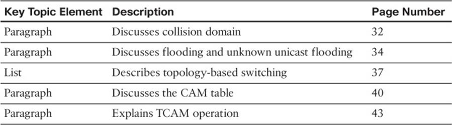
Table 2-5 Key Topics for Chapter 2
Complete Tables and Lists from Memory
There are no memory tables in this chapter.
Define Key Terms
Define the following key terms from this chapter, and check your answers in the glossary:
collision domain
flooding
unknown unicast flooding
CEF
FIB
CAM
TCAM
SDM
Use Command Reference to Check Your Memory
This section includes the most important configuration and EXEC commands covered in this chapter. It might not be necessary to memorize the complete syntax of every command, but you should remember the basic keywords that are needed.
To test your memory of the CAM-related commands, cover the right side of Table 2-6 with a piece of paper, read the description on the left side, and then see how much of the command you can remember.
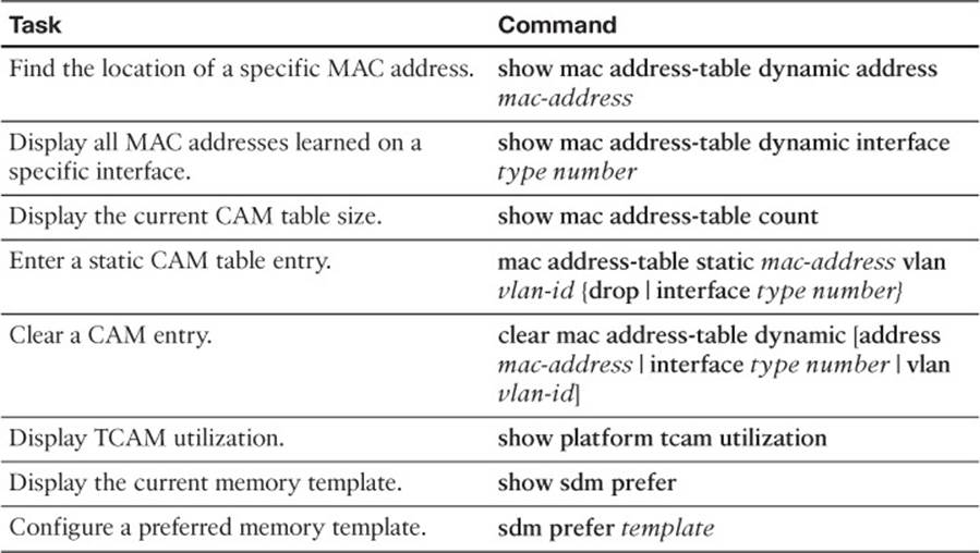
Table 2-6 Commands Used to Monitor and Manipulate the CAM Table
Remember that the CCNP exam focuses on practical or hands-on skills that are used by a networking professional. For most of the skills covered in this chapter, remember that the commands always involve the keywords mac address-table.