CCNP Routing and Switching SWITCH 300-115 Official Cert Guide (2015)
Part III. Working with Redundant Links
Chapter 7. Spanning-Tree Configuration
This chapter covers the following topics that you need to master for the CCNP SWITCH exam:
 STP Root Bridge: This section discusses the importance of identifying a root bridge and suggestions for its placement in the network. This section also presents the root bridge configuration commands.
Spanning-Tree Customization: This section covers the configuration commands that enable you to alter the spanning-tree topology.
Tuning Spanning-Tree Convergence: This section discusses how to alter, or tune, the STP timers to achieve optimum convergence times in a network.
Redundant Link Convergence: This section describes the methods that cause a network to converge more quickly after a topology change.
Monitoring STP: This section offers a brief summary of the commands that you can use to verify that an STP instance is working properly.
This chapter presents the design and configuration considerations necessary to implement the IEEE 802.1D Spanning Tree Protocol (STP) in a campus network. This chapter also discusses the commands needed to configure the STP features, previously described in Chapter 6, “Traditional Spanning Tree Protocol.”
You can also tune STP or make it converge more efficiently in a given network. This chapter presents the theory and commands needed to accomplish this.
“Do I Know This Already?” Quiz
The “Do I Know This Already?” quiz allows you to assess whether you should read this entire chapter thoroughly or jump to the “Exam Preparation Tasks” section. If you are in doubt based on your answers to these questions or your own assessment of your knowledge of the topics, read the entire chapter. Table 7-1 outlines the major headings in this chapter and the “Do I Know This Already?” quiz questions that go with them. You can find the answers in Appendix A, “Answers to the ‘Do I Know This Already?’ Quizzes.”
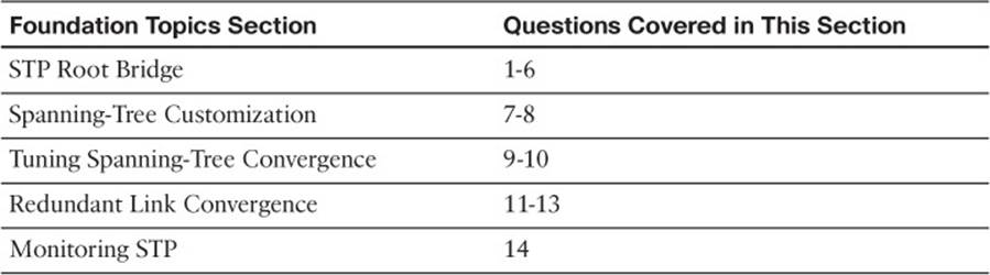
Table 7-1 “Do I Know This Already?” Foundation Topics Section-to-Question Mapping
1. Which of these is the single most important design decision to be made in a network running STP?
a. Removing any redundant links
b. Making sure all switches run the same version of IEEE 802.1D
c. Root bridge placement
d. Making sure all switches have redundant links
2. Where should the root bridge be placed on a network?
a. On the fastest switch
b. Closest to the most users
c. Closest to the center of the network
d. On the least-used switch
3. Which of the following is a result of a poorly placed root bridge in a network?
a. Bridging loops form.
b. STP topology cannot be resolved.
c. STP topology can take unexpected paths.
d. Root bridge election flapping occurs.
4. Which of these parameters should you change to make a switch become a root bridge?
a. Switch MAC address
b. Path cost
c. Port priority
d. Bridge priority
5. What is the default base 802.1D STP bridge priority on a Catalyst switch?
a. 0
b. 1
c. 32,768
d. 65,535
6. Which of the following commands is most likely to make a switch become the root bridge for VLAN 5, assuming that all switches have the default STP parameters?
a. spanning-tree root
b. spanning-tree root vlan 5
c. spanning-tree vlan 5 priority 100
d. spanning-tree vlan 5 root
7. What is the default path cost of a Gigabit Ethernet switch port?
a. 1
b. 2
c. 4
d. 19
e. 1000
8. What command can change the path cost of interface Gigabit Ethernet 1/0/3 to a value of 8?
a. spanning-tree path-cost 8
b. spanning-tree cost 8
c. spanning-tree port-cost 8
d. spanning-tree gig 1/0/3 cost 8
9. What happens if the root bridge switch and another switch are configured with different STP Hello timer values?
a. Nothing; each sends hellos at different times.
b. A bridging loop could form because the two switches are out of sync.
c. The switch with the lower Hello timer becomes the root bridge.
d. The other switch changes its Hello timer to match the root bridge
10. What network diameter value is the basis for the default STP timer calculations?
a. 1
b. 3
c. 7
d. 9
e. 15
11. Where should the STP PortFast feature be used?
a. An access layer switch port connected to a PC
b. An access layer switch port connected to a hub
c. A distribution layer switch port connected to an access layer switch
d. A core layer switch port
12. Where should the STP UplinkFast feature be enabled?
a. An access layer switch.
b. A distribution layer switch.
c. A core layer switch.
d. All these answers are correct.
13. If used, the STP BackboneFast feature should be enabled on which of these?
a. All backbone or core layer switches
b. All backbone and distribution layer switches
c. All access layer switches
d. All switches in the network
14. Which one of the following commands enables you to verify the current root bridge in VLAN 10?
a. show root vlan 10
b. show root-bridge vlan 10
c. show spanning-tree vlan 10 root
d. show running-config
Foundation Topics
STP Root Bridge
Spanning Tree Protocol (STP) and its computations are predictable; however, other factors might subtly influence STP decisions, making the resulting tree structure neither expected nor ideal.
As the network administrator, you can make adjustments to the spanning-tree operation to control its behavior. The location of the root bridge should be determined as part of the design process. You can use redundant links for load balancing in parallel, if configured correctly. You can also configure STP to converge quickly and predictably if a major topology change occurs.
Tip
By default, STP is enabled for all active VLANs and on all ports of a switch. STP should remain enabled in a network to prevent bridging loops from forming. However, you might find that STP has been disabled in some way.
If an entire instance of STP has been disabled, you can reenable it with the following global configuration command:
Switch(config)# spanning-tree vlan vlan-id
If STP has been disabled for a specific VLAN on a specific port, you can reenable it with the following interface configuration command:
Switch (config-if)# spanning-tree vlan vlan-id
Root Bridge Placement
Although STP is wonderfully automatic with its default values and election processes, the resulting tree structure might perform quite differently than expected. The root bridge election is based on the idea that one switch is chosen as a common reference point, and all other switches choose ports that have the best-cost path to the root. The root bridge election is also based on the idea that the root bridge can become a central hub that interconnects other legs of the network. Therefore, the root bridge can be faced with heavy switching loads in its central location.

If the root bridge election is left to its default state, several things can occur to result in a poor choice. For example, the slowest switch (or bridge) could be elected as the root bridge. If heavy traffic loads are expected to pass through the root bridge, the slowest switch is not the ideal candidate. Recall that the only criteria for root bridge election is that the switch must have the lowest bridge ID (bridge priority and MAC address), which is not necessarily the best choice to ensure optimal performance. If the slowest switch has the same bridge priority as the others and has the lowest MAC address, the slowest switch will be chosen as the root.
A second factor to consider relates to redundancy. If all switches are left at their default states, only one root bridge is elected, with no clear choice for a backup. What happens if that switch fails? Another root bridge election occurs, but again, the choice might not be the ideal switch or the ideal location.
The final consideration is the location of the root bridge switch. As before, an election with default switch values could place the root bridge in an unexpected location in the network. More important, an inefficient spanning-tree structure could result, causing traffic from a large portion of the network to take a long and winding path just to pass through the root bridge.
Figure 7-1 shows a portion of a hierarchical campus network that is staged for just such an inefficient topology. A single VLAN extends end to end, from the core to the access layer. End-to-end VLANs are considered a bad practice, but will serve nicely for an STP scenario.
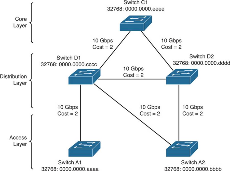
Figure 7-1 Campus Network with an Inefficient Root Bridge Election
Catalyst switches A1 and A2 are two access layer devices; Catalysts D1 and D2 form the distribution layer, and Catalyst C1 makes up the network core. Notice that most of the switches use redundant links to other layers of the hierarchy. At the time of this example, however, Switch A2 still has only a single uplink. This switch is slated for an “upgrade,” in which a redundant link will be added to the other half of the distribution layer.
As you will see, Catalyst A1 will become the root bridge because of its low MAC address. All switches have been left to their default STP states—the bridge priority of each is 32,768 (or 32,768 plus the VLAN ID, if the extended system ID is enabled). Figure 7-2 shows the converged state of STP. For the purposes of this discussion, the root ports and designated ports are simply shown on the network diagram. As an exercise, work through the spanning-tree process yourself; begin with the information shown in Figure 7-1 and see whether you arrive at the results shown inFigure 7-2. The more examples you can work out by hand, the better you will understand the entire spanning-tree process.
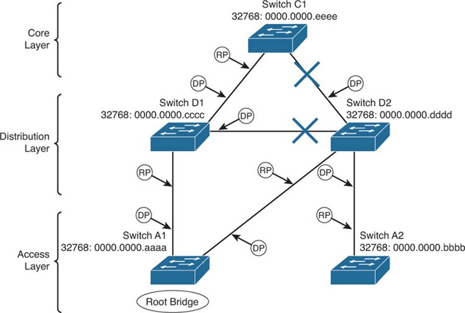
Figure 7-2 Campus Network with STP Converged
Notice that Switch A1, one of the access layer switches, has been elected the root bridge. Note the location of the X symbols over the ports that are neither root ports nor designated ports. These ports will enter the Blocking state, and no data packets will pass through them.
Finally, Figure 7-3 shows the same network with the blocking links and other clutter removed. Now you can see the true structure of the final spanning tree.
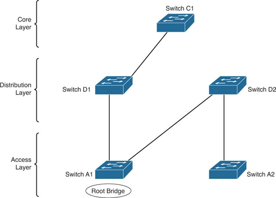
Figure 7-3 Final Spanning-Tree Structure for the Campus Network
Switch A1, an access layer switch, is the root bridge. Workstations connected to Switch A1 can reach resources elsewhere on the network by crossing through the distribution (Switch D1) and core layer (Switch C1), as expected. However, notice what has happened to the other access layer switch, Switch A2. Data frames from workstations on this switch must cross into the distribution layer (Switch D2), back into the access layer (Switch A1), back through the distribution (Switch D1), and finally into the core (Switch C1).
This action is obviously inefficient. Data frames from users connected to Switch A2 are forced to thread through the winding path that will likely become a major bottleneck.
Root Bridge Configuration
To prevent the surprises outlined in the previous section, you should always do two things:
Configure one switch as a root bridge in a determined fashion.
Configure another switch as a secondary root bridge, in case of a primary root bridge failure.
As the common reference point, the root bridge (and the secondary) should be placed near the center of the Layer 2 network. For example, a switch in the distribution layer would make a better root bridge choice than one in the access layer because more traffic is expected to pass through the distribution layer devices.
Tip
A Catalyst switch can be configured to use one of the following formats for its STP bridge ID:
Traditional 802.1D bridge priority value (16 bits), followed by the unique switch MAC address for the VLAN
The 802.1t extended system ID (4-bit priority multiplier, plus a 12-bit VLAN ID), followed by a nonunique switch MAC address for the VLAN
If the switch cannot support 1024 unique MAC addresses for its own use, the extended system ID is always enabled by default. Otherwise, the traditional method is enabled by default.
To begin using the extended system ID method, you can use the following global configuration command:
Switch(config)# spanning-tree extend system-id
Otherwise, you can use the traditional method by beginning the command with the no keyword.
You can configure a Catalyst switch to become the root bridge using one of two methods, which are configured as follows:
Manually setting the bridge priority value so that a switch is given a lower-than-default bridge ID value to win a root bridge election. You must know the bridge priorities of every other switch in a VLAN so that you can choose a value that is less than all the others. The command to accomplish this is as follows:
Switch(config)# spanning-tree vlan vlan-list priority bridge-priority
The bridge-priority value defaults to 32,768, but you can also assign a value of 0 to 65,535. If STP extended system ID is enabled, the default bridge-priority is 32,768 plus the VLAN number. In that case, the value can range from 0 to 61,440, but only as multiples of 4096. A lower bridge priority is preferable.
Remember that Catalyst switches run one instance of STP for each VLAN (PVST+), so the VLAN ID must always be given. You should designate an appropriate root bridge for each VLAN. For example, you could use the following command to set the bridge priority for VLAN 5 and VLANs 100 through 200 to 4096:
Switch(config)# spanning-tree vlan 5,100-200 priority 4096
If you are not sure that your priority value will be accepted, enter it anyway. The switch will respond with a list of accepted values that are multiples of 4096:
Switch(config)#spanning vlan 5,100-200 priority 4000
% Bridge Priority must be in increments of 4096.
% Allowed values are:
0 4096 8192 12288 16384 20480 24576 28672
32768 36864 40960 45056 49152 53248 57344 61440
Switch(config)#
Causing the would-be root bridge switch to choose its own priority, based on some assumptions about other switches in the network. You can accomplish this with the following command:
Switch(config)# spanning-tree vlan vlan-id root {primary |
secondary} [diameter diameter]
This command is actually a macro on the switch that executes several other commands. The result is a more direct and automatic way to force one switch to become the root bridge. Notice that the actual bridge priorities are not given in the command. Instead, the switch modifies its STP values according to the current values in use within the active network. These values are modified only once, when the macro command is issued. Use the primary keyword to make the switch attempt to become the primary root bridge. This command modifies the switch’s bridge priority value to become less than the bridge priority of the current root bridge. If the current root priority is more than 24,576, the local switch sets its priority to 24,576. If the current root priority is less than that, the local switch sets its priority to 4096 less than the current root.
For the secondary root bridge, the root priority is set to an artificially low value of 28,672. There is no way to query or listen to the network to find another potential secondary root simply because there are no advertisements or elections of secondary root bridges. Instead, the fixed secondary priority is used under the assumption that it will be less than the default priorities (32,768) that might be used on switches elsewhere.
You can also modify the network diameter by adding the diameter keyword to this command. This modification is discussed further in the “Tuning Spanning-Tree Convergence” section, later in the chapter.
As a final example, consider a switch that is currently using its default bridge priority for VLAN 100. In the extended system-id mode, the default priority is 32,768 plus 100 (the VLAN number). The output in Example 7-1 demonstrates this under the bridge ID information. The default priority is greater than the current root bridge priority of 4200, so the local switch cannot become the root.
Example 7-1 Displaying the STP Bridge Priority Values
Switch# show spanning-tree vlan 100
VLAN0100
Spanning tree enabled protocol ieee
Root ID Priority 4196
Address 000b.5f65.1f80
Cost 4
Port 1 (GigabitEthernet1/0/1)
Hello Time 2 sec Max Age 20 sec Forward Delay 15 sec
Bridge ID Priority 32868 (priority 32768 sys-id-ext 100)
Address 000c.8554.9a80
Hello Time 2 sec Max Age 20 sec Forward Delay 15 sec
Aging Time 300
[output omitted]
As an alternative, the automatic method is used to attempt to make the switch become root for VLAN 100, using the command demonstrated in Example 7-2.
Example 7-2 Using a Macro Command to Configure a Root Bridge
Switch(config)# spanning-tree vlan 100 root primary
% Failed to make the bridge root for vlan 100
% It may be possible to make the bridge root by setting the priority
% for some (or all) of these instances to zero.
Switch(config)#
Why did this method fail? The current root bridge has a bridge priority of 4196. Because that priority is less than 24,576, the local switch will try to set its priority to 4096 less than the current root. Although the resulting priority would be 100, the local switch is using an extended system ID, which requires bridge priority values that are multiples of 4096. The only value that would work is 0, but the automatic method will not use it. Instead, the only other option is to manually configure the bridge priority to 0 with the following command:
Switch(config)# spanning-tree vlan 100 priority 0
Remember that on switches that use an extended system ID, the bridge priority is the configured priority (multiple of 4096) plus the VLAN number. Even though the priority was set to 0 with the previous command, the switch is actually using a value of 100—priority 0 plus VLAN number 100, as the output in Example 7-3 reveals.
Example 7-3 Displaying Bridge Priorities with Extended System IDs
Switch# show spanning-tree vlan 100
VLAN0100
Spanning tree enabled protocol ieee
Root ID Priority 100
Address 000c.8554.9a80
This bridge is the root
Hello Time 2 sec Max Age 20 sec Forward Delay 15 sec
Bridge ID Priority 100 (priority 0 sys-id-ext 100)
Address 000c.8554.9a80
Hello Time 2 sec Max Age 20 sec Forward Delay 15 sec
Aging Time 300
[output omitted]
Note
The spanning-tree vlan vlan-id root command will not be shown in a Catalyst switch configuration because the command is actually a macro executing other switch commands. The actual commands and values produced by the macro will be shown, however. For example, the macro can potentially adjust the four STP values, as follows:
Switch(config)# spanning-tree vlan 1 root primary
vlan 1 bridge priority set to 24576
vlan 1 bridge max aging time unchanged at 20
vlan 1 bridge hello time unchanged at 2
vlan 1 bridge forward delay unchanged at 15
Be aware that this macro does not guarantee that the switch will become the root and maintain that status. After the macro is used, it is entirely possible for another switch in the network to have its bridge priority configured to a lower value. The other switch would become the new root, displacing the switch that ran the macro.
On the root, it is usually good practice to directly modify the bridge priority to an artificially low value (even priority 1 or 0) with the spanning-tree vlan vlan-id priority bridge-priority command. This makes it more difficult for another switch in the network to win the root bridge election, unless it is manually configured with a priority that is even lower.
Spanning-Tree Customization
The most important decision you can make when designing your spanning-tree topology is the placement of the root bridge. Other decisions, such as the exact loop-free path structure, will occur automatically as a result of the spanning-tree algorithm (STA). Occasionally, the path might need additional tuning, but only under special circumstances and after careful consideration.
Recall the sequence of four criteria that STP uses to choose a path:
1. Lowest bridge ID
2. Lowest root path cost
3. Lowest sender bridge ID
4. Lowest sender port ID
The previous section discussed how to tune a switch’s bridge ID to force it to become the root bridge in a network. You can also change the bridge priority on a switch to influence the value it uses in the sender bridge ID that it announced as it relays bridge protocol data units (BPDUs) to other neighboring switches.
Only the automatic STP computation has been discussed, using the default switch port costs to make specific path decisions. The following sections discuss ways you can influence the exact topology that results.
Tuning the Root Path Cost
The root path cost for each active port of a switch is determined by the cumulative cost as a BPDU travels along. As a switch receives a BPDU, the port cost of the receiving port is added to the root path cost in the BPDU. The port or port path cost is inversely proportional to the port’s bandwidth. If desired, a port’s cost can be modified from the default value.
Note
Before modifying a switch port’s path cost, you should always calculate the root path costs of other alternative paths through the network. Changing one port’s cost might influence STP to choose that port as a root port, but other paths still could be preferred. You also should calculate a port’s existing path cost to determine what the new cost value should be. Careful calculation will ensure that the desired path indeed will be chosen.

Use the following interface configuration command to set a switch port’s path cost:
Switch (config-if)# spanning-tree [vlan vlan-id] cost cost
If the vlan parameter is given, the port cost is modified only for the specified VLAN. Otherwise, the cost is modified for the port as a whole (all active VLANs). The cost value can range from 1 to 200,000,000. There are standard or default values that correspond to port bandwidth, as shown in Table 7-2.
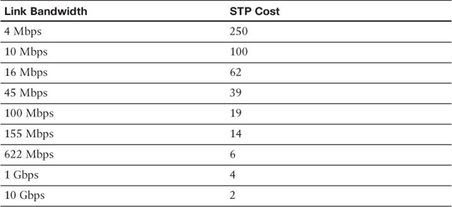
Table 7-2 STP Port Cost
For example, a Gigabit Ethernet interface has a default port cost of 4. You can use the following command to change the cost to 2, but only for VLAN 10:
Switch(config-if)# spanning-tree vlan 10 cost 2
You can see the port cost of an interface by using the following command:
Switch# show spanning-tree interface type member/module/number [cost]
As an example, Gigabit Ethernet 1/0/1 is configured as a trunk port, carrying VLANs 1, 10, and 20. Example 7-4 shows the port cost for each of the VLANs.
Example 7-4 Displaying STP Port Cost Values on an Interface
Switch# show spanning-tree interface gigabitEthernet1/0/1
Vlan Role Sts Cost Prio.Nbr Type
----------------- ---- --- ---------- -------- -----------------------------
VLAN0001 Root FWD 4 128.1 P2p
VLAN0010 Desg FWD 2 128.1 P2p
VLAN0020 Root FWD 4 128.1 P2p
Tuning the Port ID
The fourth criteria of an STP decision is the port ID. The port ID value that a switch uses is actually a 16-bit quantity: 8 bits for the port priority, and 8 bits for the port number. The port priority is a value from 0 to 255 and defaults to 128 for all ports. The port number can range from 0 to 255 and represents the port’s actual physical mapping. Port numbers generally begin with 1 at port 1/0/1 and increment across each module, then across each stack member or slot. However, the numbers might not be completely intuitive or consecutive because each member or module is assigned a particular range of numbers. In addition, ports that are bundled into an EtherChannel or port channel interface always have a higher port ID than they would if they were not bundled.
Tip
Port numbers are usually intuitive on a single fixed configuration switch. For example, the STP port number can simply be the interface number, from 1 to 48. However, it is not easy to find the STP port number in a switch with many modules and many ports. Notice how Gigabit Ethernet 1/0/1 is known as port number 1 (shown as Prio.Nbr 128.1), whereas 2/0/44 is known as port number 102 in the following example:
Switch# show spanning-tree interface gi1/0/1
Vlan Role Sts Cost Prio.Nbr Type
------------------- ---- --- --------- -------- ----------------
VLAN0100 Desg FWD 4 128.1 P2p Edge
Switch# show spanning-tree interface gi2/0/44
Vlan Role Sts Cost Prio.Nbr Type
------------------- ---- --- --------- -------- ----------------
VLAN0100 Desg FWD 4 128.102 P2p Edge
Switch#
Obviously, a switch port’s port number is fixed because it is based only on its hardware location or index. The port ID, however, can be modified to influence an STP decision by using the port priority. You can configure the port priority with this interface-configuration command:
Switch(config-if)# spanning-tree [vlan vlan-list] port-priority port-priority
You can modify the port priority for one or more VLANs by using the vlan parameter. The VLAN numbers are given as vlan-list, a list of single values or ranges of values separated by commas. Otherwise, the port priority is set for the port as a whole (all active VLANs). The value of port-priority can range from 0 to 255 and defaults to 128. A lower port priority value indicates a more preferred path toward the root bridge.
As an example, you can use the following command sequence to change the port priority of Gigabit Ethernet 2/0/44 from 128 (the default) to 64 for VLANs 10 and 100:
Switch(config)# interface gigabitethernet 2/0/44
Switch(config-if)# spanning-tree vlan 10,100 port-priority 64
You can confirm the changes with the show spanning-tree interface command, as demonstrated in Example 7-5.
Example 7-5 Confirming STP Port Priority Values After Configuration
Switch# show spanning-tree interface gigabitEthernet 2/0/44
Vlan Role Sts Cost Prio.Nbr Type
----------------- ---- --- --------- -------- -----------------------------
VLAN0010 Desg FWD 4 64.102 Edge P2p
VLAN0100 Desg FWD 4 64.102 Edge P2p
VLAN0200 Desg FWD 4 128.102 Edge P2p
Switch#
Tuning Spanning-Tree Convergence
STP uses several timers, a sequence of states that ports must move through, and specific topology change conditions to prevent bridging loops from forming in a complex network. Each of these parameters or requirements is based on certain default values for a typical network size and function. For the majority of cases, the default STP operation is sufficient to keep the network loop free and enable users to communicate.
However, in certain situations, the default STP can cause network access to be delayed while timers expire and while preventing loops on links where loops are not possible. For example, when a single PC is connected to a switch port, a bridging loop is simply not possible. Another situation relates to the size of a Layer 2 switched network: The default STP timers are based on a benchmark network size.
In a network that is smaller, waiting until the default timer values expire might not make sense when they could be safely set to shorter values. In situations like this, you can safely make adjustments to the STP convergence process for more efficiency.
Modifying STP Timers
Recall that STP uses three timers to keep track of various port operation states and communication between bridges. The three STP timers can be adjusted by using the commands documented in the sections that follow. Remember that the timers need to be modified only on the root bridge because the root bridge propagates all three timer values throughout the network as fields in the configuration BPDU.
Manually Configuring STP Timers
Use one or more of the following global configuration commands to modify STP timers:
Switch(config)# spanning-tree [vlan vlan-id] hello-time seconds
Switch(config)# spanning-tree [vlan vlan-id] forward-time seconds
Switch(config)# spanning-tree [vlan vlan-id] max-age seconds
Notice that the timers can be changed for a single instance (VLAN) of STP on the switch by using the vlan vlan-id parameters. If you omit the vlan keyword, the timer values are configured for all instances (all VLANs) of STP on the switch.
The Hello timer triggers periodic “hello” (actually, the configuration BPDU) messages that are sent from the root to other bridges in the network. This timer also sets the interval in which a bridge expects to hear a hello relayed from its neighboring bridges. Configuration BPDUs are sent every 2 seconds, by default. You can modify the Hello timer with the hello-time keyword, along with a value of 1 to 10 seconds, as in the following command:
Switch(config)# spanning-tree hello-time 1
The Forward Delay timer determines the amount of time a port stays in the Listening state before moving into the Learning state, and how long it stays in the Learning state before moving to the Forwarding state. You can modify the Forward Delay timer with the forward-time keyword. The default value is 15 seconds, but this can be set to a value of 4 to 30 seconds. This timer should be modified only under careful consideration because the value depends on the diameter of the network and the propagation of BPDUs across all switches. A value that is too low allows loops to form, possibly crippling a network.
The Max Age timer specifies a stored BPDU’s lifetime that has been received from a neighboring switch with a designated port. Suppose that BPDUs are being received on a nondesignated switch port every 2 seconds, as expected. Then an indirect failure, or one that does not involve a physical link going down, occurs that prevents BPDUs from being sent. The receiving switch waits until the Max Age timer expires to listen for further BPDUs. If none is received, the nondesignated port moves into the Listening state, and the receiving switch generates configuration BPDUs. This port then becomes the designated port to restore connectivity on the segment.
To modify the Max Age timer, use the max-age keyword. The timer value defaults to 20 seconds but can be set from 6 to 40 seconds.
Automatically Configuring STP Timers
Modifying STP timers can be tricky, given the conservative nature of the default values and the calculations needed to derive proper STP operation. Timer values are basically dependent on the Hello Time and the switched network’s diameter, in terms of switch hops. Catalyst switches offer a single command that can change the timer values in a more controlled fashion. As described earlier, the spanning-tree vlan vlan-list root macro command is a better tool to use than setting the timers with the individual commands. This global configuration command has the following syntax:
Switch(config)# spanning-tree vlan vlan-list root {primary | secondary} [diameter
diameter [hello-time hello-time]]
Here, STP timers will be adjusted according to the formulas specified in the 802.1D standard by giving only the network’s diameter (the maximum number of switches that traffic will traverse across a Layer 2 network) and an optional hello-time. If you do not specify a hello time, the default value of 2 seconds is assumed.
This command can be used only on a per-VLAN basis to modify the timers for a particular VLAN’s spanning tree instance. The network diameter can be a value from 1 to 7 switch hops; the default STP timers are based on a diameter of 7. Because this command makes a switch become the root bridge, all the modified timer values resulting from this command will be propagated to other switches through the configuration BPDU.
Suppose, for example, that a small network consists of three switches connected in a triangle fashion. The command output in Example 7-6 shows the current (default) STP timer values that are in use for VLAN 100.
Example 7-6 Displaying the STP Timer Values in Use
Switch# show spanning-tree vlan 100
VLAN0100
Spanning tree enabled protocol ieee
Root ID Priority 100
Address 000c.8554.9a80
This bridge is the root
Hello Time 2 sec Max Age 20 sec Forward Delay 15 sec
Bridge ID Priority 100 (priority 0 sys-id-ext 100)
Address 000c.8554.9a80
Hello Time 2 sec Max Age 20 sec Forward Delay 15 sec
Aging Time 300
[output omitted]
The longest path that a packet can take through the sample network is three switches. This is considerably less than the reference diameter of seven that is used to calculate the default timer values. Therefore, you can safely assume that this network diameter is three, provided that no additional switches will be added to lengthen the longest path. Suppose that a hello time of 1 second is also desired, to shorten the time needed to detect a dead neighbor. The following command attempts to make the local switch become the root bridge and automatically adjusts the STP timers:
Switch(config)# spanning-tree vlan 100 root primary diameter 3 hello-time 1
You can confirm the new timer values with the show spanning-tree vlan vlan-id command, as demonstrated in Example 7-7.
Example 7-7 Confirming STP Timer Configuration Changes
Switch# show spanning-tree vlan 100
VLAN0100
Spanning tree enabled protocol ieee
Root ID Priority 100
Address 000c.8554.9a80
This bridge is the root
Hello Time 1 sec Max Age 7 sec Forward Delay 5 sec
Bridge ID Priority 100 (priority 0 sys-id-ext 100)
Address 000c.8554.9a80
Hello Time 1 sec Max Age 7 sec Forward Delay 5 sec
Aging Time 300
Redundant Link Convergence
Some additional methods allow faster STP convergence if a link failure occurs:
 PortFast: Enables fast connectivity to be established on access layer switch ports to workstations that are booting
UplinkFast: Enables fast-uplink failover on an access layer switch when dual uplinks are connected into the distribution layer
BackboneFast: Enables fast convergence in the network backbone or core layer switches after a spanning-tree topology change occurs
Instead of modifying timer values, these methods work by controlling convergence on specifically located ports within the network hierarchy.
Tip
The STP has been enhanced to allow almost instantaneous topology changes instead of having to rely on these Cisco-proprietary extensions. This enhancement is known as the Rapid Spanning Tree Protocol, or IEEE 802.1w, and is covered in Chapter 9, “Advanced Spanning Tree Protocol.” You should become familiar with the topics in this chapter first because they provide the basis for the concepts in Chapter 9.
PortFast: Access Layer Nodes
An end-user workstation is usually connected to a switch port in the access layer. If the workstation is powered off and then turned on, the switch will sense that the port link status has gone down and back up. The port will not be in a usable state until STP cycles from the Blocking state to the Forwarding state. With the default STP timers, this transition takes at least 30 seconds (15 seconds for Listening to Learning, and 15 seconds for Learning to Forwarding). Therefore, the workstation cannot transmit or receive any useful data until the Forwarding state finally is reached on the port.
Tip
Port initialization delays of up to 50 seconds can be observed. As discussed, 30 of these seconds are due to the STP state transitions. If a switch port is running Port Aggregation Protocol (PAgP) to negotiate EtherChannel configuration, an additional 20-second delay can occur.
On switch ports that connect only to single workstations or specific devices, bridging loops never should be possible. The potential for a loop exists only if the workstation had additional connections back into the network and if it were bridging traffic itself. For example, this can happen on PCs that are running Windows when network bridging has been enabled. In most situations, this is not very likely to happen.
Catalyst switches offer the PortFast feature, which shortens the Listening and Learning states to a negligible amount of time. When a workstation link comes up, the switch immediately moves the PortFast port into the Forwarding state. Spanning-tree loop detection is still in operation, however, and the port moves into the Blocking state if a loop is ever detected on the port.
By default, PortFast is disabled on all switch ports. You can configure PortFast as a global default, affecting all switch ports with a single command. All ports that are configured for access mode (nontrunking) will have PortFast automatically enabled. You can use the following global configuration command to enable PortFast as the default:
Switch(config)# spanning-tree portfast default
You can also enable or disable the PortFast feature on specific switch ports by using the following interface configuration command:
Switch(config-if)# [no] spanning-tree portfast
Obviously, you should not enable PortFast on a switch port that is connected to another switch because bridging loops could form. One other benefit of PortFast is that Topology Change Notification (TCN) BPDUs are not sent when a switch port in PortFast mode goes up or down. This simplifies the TCN transmission on a large network when end-user workstations are coming up or shutting down.
Tip
You can also use a macro configuration command to force a switch port to support a single host. The following command enables STP PortFast, sets the port to access (nontrunking) mode, and disables PAgP to prevent the port from participating in an EtherChannel:
Switch(config)# interface type member/module/number
Switch(config-if)# switchport host
switchport mode will be set to access
spanning-tree portfast will be enabled
channel group will be disabled
You can display the current PortFast status with the following command:
Switch# show spanning-tree interface type member/module/number portfast
For example, the following output shows that port Gigabit Ethernet 1/0/10 supports only access VLAN 10 and has PortFast enabled:
Switch# show spanning-tree interface gigabitethernet 1/0/10 portfast
VLAN0010 enabled
Switch#
UplinkFast: Access Layer Uplinks
Consider an access layer switch that has redundant uplink connections to two distribution layer switches. Normally, one uplink would be in the Forwarding state and the other would be in the Blocking state. If the primary uplink went down, up to 50 seconds could elapse before the redundant uplink could be used.
The UplinkFast feature on Catalyst switches enables leaf-node switches or switches at the ends of the spanning-tree branches to have a functioning root port while keeping one or more redundant or potential root ports in Blocking mode. When the primary root port uplink fails, another blocked uplink immediately can be brought up for use.
Tip
Many Catalyst switches have two built-in, high-speed uplink ports (Gigabit Ethernet, for example). You might get the idea that UplinkFast can only toggle between two leaf-node uplink ports. This is entirely untrue. UplinkFast keeps a record of all parallel paths to the root bridge. All uplink ports but one are kept in the Blocking state. If the root port fails, the uplink with the next-lowest root path cost is unblocked and used without delay.
To enable the UplinkFast feature, use the following global configuration command:
Switch(config)# spanning-tree uplinkfast [max-update-rate pkts-per-second]
When UplinkFast is enabled, it is enabled for the entire switch and all VLANs. UplinkFast works by keeping track of possible paths to the root bridge. Therefore, the command is not allowed on the root bridge switch. UplinkFast also makes some modifications to the local switch to ensure that it does not become the root bridge and that the switch is not used as a transit switch to get to the root bridge. In other words, the goal is to keep UplinkFast limited to leaf-node switches that are farthest from the root.
First, the switch’s bridge priority is raised to 49,152, making it unlikely that the switch will be elected to root bridge status. The port cost of all local switch ports is incremented by 3000, making the ports undesirable as paths to the root for any downstream switches.
The command also includes a max-update-rate parameter. When an uplink on a switch goes down, UplinkFast makes it easy for the local switch to update its bridging table of MAC addresses to point to the new uplink. However, UplinkFast also provides a mechanism for the local switch to notify other upstream switches that stations downstream (or within the access layer) can be reached over the newly activated uplink.
The switch accomplishes this by sending dummy multicast frames to destination 0100.0ccd.cdcd on behalf of the stations contained in its CAM table. The MAC addresses are used as the source addresses in the dummy frames, as if the stations actually had sent them. The idea is to quickly send the multicast frames over the new uplink, giving upstream hosts a chance to receive the frames and learn of the new path to those source addresses.
These multicast frames are sent out at a rate specified by the max-update-rate parameter in packets per second. This limits the amount of bandwidth used for the dummy multicasts if the CAM table is quite large. The default is 150 packets per second (pps), but the rate can range from 0 to 65,535 pps. If the value is 0, no dummy multicasts are sent.
Tip
You can use the following command to display the current status of STP UplinkFast:
Switch# show spanning-tree uplinkfast
UplinkFast is enabled
Station update rate set to 150 packets/sec.
UplinkFast statistics
Number of transitions via UplinkFast (all VLANs) : 2
Number of proxy multicast addresses transmitted (all VLANs) : 52
Name Interface List
--------------------- --------------------------------
VLAN0001 Gi1/0/1(fwd)
VLAN0010 Gi1/0/1(fwd)
VLAN0100 Gi1/0/1(fwd)
Switch#
BackboneFast: Redundant Backbone Paths
In the network backbone, or core layer, a different method is used to shorten STP convergence. BackboneFast works by having a switch actively determine whether alternative paths exist to the root bridge, in case the switch detects an indirect link failure. Indirect link failures occur when a link that is not directly connected to a switch fails.
A switch detects an indirect link failure when it receives inferior BPDUs from its designated bridge on either its root port or a blocked port. (Inferior BPDUs are sent from a designated bridge that has lost its connection to the root bridge, making it announce itself as the new root.)
Normally, a switch must wait for the Max Age timer to expire before responding to the inferior BPDUs. However, BackboneFast begins to determine whether other alternative paths to the root bridge exist according to the following port types that received the inferior BPDU:
 If the inferior BPDU arrives on a port in the Blocking state, the switch considers the root port and all other blocked ports to be alternative paths to the root bridge.
If the inferior BPDU arrives on the root port itself, the switch considers all blocked ports to be alternative paths to the root bridge.
If the inferior BPDU arrives on the root port and no ports are blocked, however, the switch assumes that it has lost connectivity with the root bridge. In this case, the switch assumes that it has become the root bridge, and BackboneFast allows it to do so before the Max Age timer expires.
Detecting alternative paths to the root bridge also involves an interactive process with other bridges. If the local switch has blocked ports, BackboneFast begins to use the Root Link Query (RLQ) protocol to see whether upstream switches have stable connections to the root bridge.
First, RLQ Requests are sent out. If a switch receives an RLQ Request and either is the root bridge or has lost connection to the root, it sends an RLQ Reply. Otherwise, the RLQ Request is propagated on to other switches until an RLQ Reply can be generated. On the local switch, if an RLQ Reply is received on its current root port, the path to the root bridge is intact and stable. If it is received on a nonroot port, an alternative root path must be chosen. The Max Age timer immediately is expired so that a new root port can be found.
BackboneFast is simple to configure and operates by short-circuiting the Max Age timer when needed. Although this function shortens the time a switch waits to detect a root path failure, ports still must go through full-length Forward Delay timer intervals during the Listening and Learning states. Where PortFast and UplinkFast enable immediate transitions, BackboneFast can reduce the maximum convergence delay only from 50 to 30 seconds.
To configure BackboneFast, use the following global configuration command:
Switch(config)# spanning-tree backbonefast
When used, BackboneFast should be enabled on all switches in the network because BackboneFast requires the use of the RLQ Request and Reply mechanism to inform switches of Root Path stability. The RLQ protocol is active only when BackboneFast is enabled on a switch. By default, BackboneFast is disabled.
Tip
You can verify the current BackboneFast state with the following command:
Switch# show spanning-tree backbonefast
BackboneFast is enabled
Switch#
Monitoring STP
Because the STP running in a network uses several timers, costs, and dynamic calculations, predicting the current state is difficult. You can use a network diagram and work out the STP topology by hand, but any change on the network could produce an entirely different outcome. Then, figure in something like PVST+, in which you have one instance of STP running for each VLAN present. Obviously, simply viewing the STP status on the active network devices would be better.
You can display information about many aspects of the STP from a Catalyst switch command-line interface (CLI). Specifically, you need to find out the current root bridge and its location in the network. You also might want to see the bridge ID of the switch where you are connected, to see how it participates in STP. Use the information in Table 7-3 to determine what command is useful for what situation.
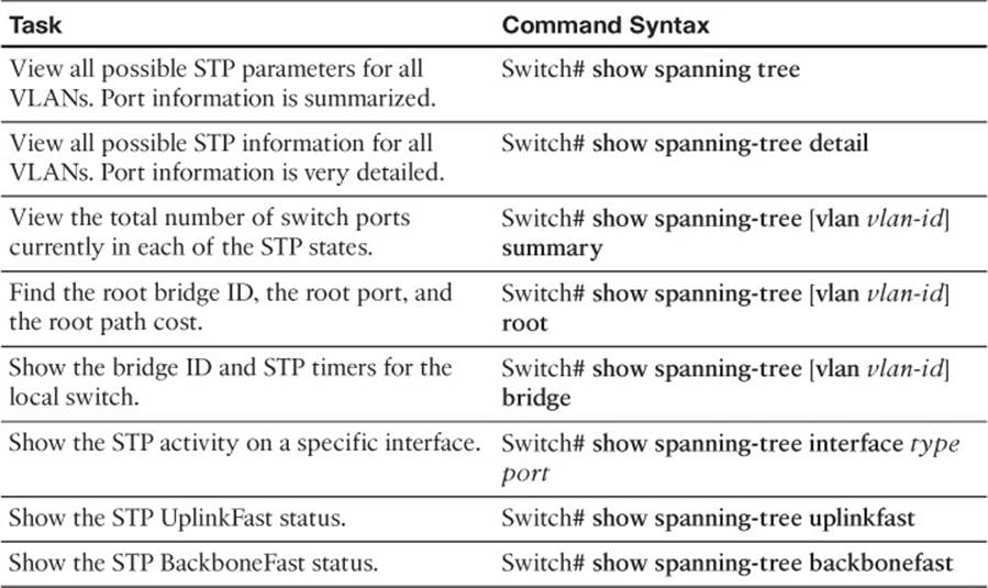
Table 7-3 Commands for Displaying Spanning-Tree Information
Exam Preparation Tasks
Review All Key Topics
Review the most important topics in the chapter, noted with the Key Topic icon in the outer margin of the page. Table 7-4 lists a reference of these key topics and the page numbers on which each is found.
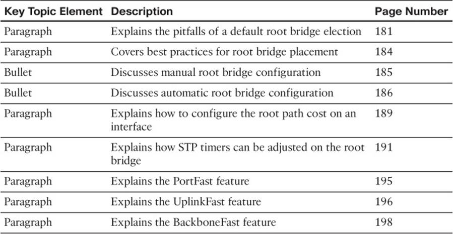
Table 7-4 Key Topics for Chapter 7
Complete Tables and Lists from Memory
There are no memory tables in this chapter.
Define Key Terms
Define the following key terms from this chapter, and check your answers in the glossary:
PortFast
UplinkFast
BackboneFast
Use Command Reference to Check Your Memory
This section includes the most important configuration and EXEC commands covered in this chapter. It might not be necessary to memorize the complete syntax of every command, but you should remember the basic keywords that are needed.
To test your memory of the STP configuration commands, cover the right side of Table 7-5 with a piece of paper, read the description on the left side, and then see how much of the command you can remember.
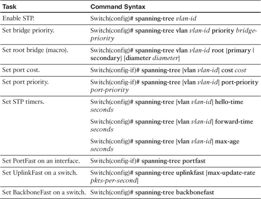
Table 7-5 STP Configuration Commands
Remember that the CCNP exam focuses on practical or hands-on skills that are used by a networking professional. For the skills covered in this chapter, notice that the commands always begin with the keyword spanning-tree.
All materials on the site are licensed Creative Commons Attribution-Sharealike 3.0 Unported CC BY-SA 3.0 & GNU Free Documentation License (GFDL)
If you are the copyright holder of any material contained on our site and intend to remove it, please contact our site administrator for approval.
© 2016-2026 All site design rights belong to S.Y.A.