Programming for Musicians and Digital Artists: Creating music with ChucK (2015)
Part 2. Now it gets really interesting!
Now that you know the basics, part 2 will cover more advanced topics and features of the ChucK language. Chapter 6 introduces a number of new Unit Generators (UGens), which are ChucK’s built-in audio processing and synthesis objects. UGens cover many models and techniques for sound synthesis and audio effects, so you’ll know even more ways to make interesting sounds. Chapter 7 continues our coverage of UGens, introducing many of the physical, modal (resonant), and particle synthesis UGens available via the Synthesis ToolKit (STK).
Chapter 8 introduces multithreading and concurrency, the ability to run many programs or functions at the same time. Chapter 9 introduces object-oriented programming (OOP) and how you can create your own objects and classes to use in your code. By the end of this chapter, you’ll know how to create smart musical instruments, and even play objects in code, which you can then in turn use to do your musical bidding.
Chapter 10 covers Events, which allow ChucK programs to signal each other. Events also allow ChucK to respond to signals and data from the “outside world,” such as using your keyboard, mouse, or joystick for real-time control over your programs and compositions.
Chapter 11 looks at ways that ChucK can communicate with other programs, computers, and control devices. We briefly cover how MIDI can be used with ChucK, both using an external MIDI device (such as a keyboard) to play ChucK as a synthesizer, and how ChucK can control other synthesizers, both software and external hardware synths. We also introduce Open Sound Control (OSC), which is another standard way for music programs and devices to communicate. We then look at Serial Input/Output, which allows us to talk to even more devices. We conclude by talking about ways to extend ChucK itself.
Chapter 6. Unit generators: ChucK objects for sound synthesis and processing
This chapter covers
· More ChucK oscillators
· Envelope generators
· Frequency modulation synthesis
· More about sound and acoustics, to motivate and inspire
· Intro to physical modeling synthesis
Okay, here’s where it really gets good. Having covered much of how ChucK works, we can start digging into the specifics of synthesis and processing in ChucK. At the heart of the power of ChucK for audio synthesis and processing is the concept of UGens. You’ve already used UGens, starting with our “Hello Sine” example, where you ChucKed a SinOsc UGen to the dac to hear your first sound. You continued to use UGens in pretty much every program you’ve written so far. The nice thing is that you don’t have to worry about how each UGen makes or processes sound; the designer of that UGen took care of that part. You only need to know what they can do and how to use them.
In this chapter, we’ll introduce some of the UGens built into ChucK that you can use to make your music/sound making and processing very easy. You’ll use a new type of oscillator (PulseOsc) to make sci-fi techno sounds. Up until now you’ve used gain to turn your sounds and musical notes on and off abruptly, but in this chapter you’ll learn about and use envelope generators, which generate smooth functions in time. With envelopes, you’ll be able to turn your notes on and off smoothly, like a DJ fading the sounds of turntables in and out, or a violinist starting and stopping the bowing of a note, which isn’t abrupt, but has smooth ramps at the start and end. We’ll introduce frequency modulation (FM) synthesis as well as sound synthesis and processing by physical modeling, where rather than synthesizing a desired output waveform, you model and compute the physics of waves as they vibrate and propagate (travel) inside instruments and rooms. In this chapter you’ll build simple physical models of a plucked string and of the reverberation patterns in a room. We’ll set the stage for the next chapter where we look at a lot of ChucK’s built-in physical modeling instrument UGens. So let’s get started!
Synthesis history: unit generators
The UGen idea goes far back, dating to analog synthesizer days when oscillators, noise sources, and other signal generators were patched through filters and other processors into mixers and eventually to amps and speakers. In 1967, when many synth pioneers were working with analog synthesis, Max Mathews (called by many the Father of Computer Music) at Bell Laboratories posed (and implemented) the idea of synthesizing sound and music digitally by connecting UGens to form instruments and using other programs to read scores to control it all to make music. Most computer music languages (ChucK included) since then have held to this basic idea.
6.1. ChucK’s special UGens: adc, dac, and blackhole
You’ve been using the dac UGen throughout this book, to allow you to connect other UGens to the outside world of your speakers or headphones via your sound hardware. ChucK has two such special UGens that connect you to the outside world via your audio hardware. The reason they’re special is that these three UGens (adc, dac, and blackhole) are always there, meaning that you don’t have to declare them like other UGens such as SinOsc, SndBuf, or Impulse. Recall that when you used these other types of unit generators, you had to declare them in this manner:
SinOsc s => dac;
or
Impulse imp => ResonZ filter => dac;
But you didn’t need to declare a dac variable name, because dac is always there, and there’s only one of them. So you just call it simply dac.
The other special outside world UGen is called adc (for analog-to-digital converter), and it allows you to get sound into your computer from a built-in microphone, a mic-in or line-in jack, or other inputs via an externally connected sound card. To test this, you can make a connection from the input to the output on your computer. You might use the code in the following listing.
Listing 6.1. Connecting audio input to output using adc and dac
//connect audio input to audio output through Gain UG
adc => Gain g => dac;
//let it run for 10 seconds
10.0 :: second => now;
Caution!
CAUTION! CAUTION! Be extremely careful before you execute this code, making sure that there won’t be an ear-splitting feedback loop (as can happen when sound from your speakers gets back into your microphone). Plug in headphones, or turn your speaker volume way down before hooking the adc to the dac (running this code).
Strictly speaking, you don’t need the Gain UGen between the adc and the dac, but you should always avoid connecting the adc to the dac directly. The reason for this is that adc and dac are the only persistent UGens in all of ChucK, and once connected they stay connected until explicitly disconnected (by unChucKing using =<). In listing 6.1, however, the Gain UGen you named g will disappear after the code has finished executing, thus breaking the connection from input to output. Note that you didn’t have to declare a variable of type adc and give it a name, as you had to for the Gain UGen, and you didn’t have to name your dac. Both adc and dac are unique in this way. All other unit generators require you to make a variable and give it a name if you want to use one.
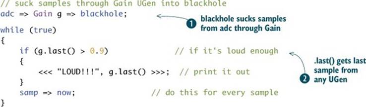
So now you know how to listen to a mic connected or built into your computer, but what if you want to use a microphone to detect if there’s a loud sound nearby, so you can do interesting things based on that, but you don’t want to listen directly to that microphone sound? ChucK has one more special UGen called blackhole, which acts like a dac that isn’t connected to any sound device. There are many reasons why you might want to connect sound to an output that doesn’t make sound, but the main one is if you want to do signal processing of some type (like pitch detection) or to inspect a signal (like the loud sound detector we mentioned previously), without connecting that path directly to any sound output. The blackhole UGen serves to suck samples from any and all UGens that are connected to it. Those UGens wouldn’t compute any new sound otherwise, because ChucK is clever about being efficient and not computing any samples that don’t get used somewhere. The blackhole serves to use those samples, even though you never hear them.
Listing 6.2 is an example of using blackhole to do something useful, specifically to keep an eye on the input from the adc and print out a message if things get too loud ![]() . The g.last() in the if conditional
. The g.last() in the if conditional ![]() returns the last sample passed through the Gain UGen. You can change the value that’s compared (0.9) to any value you like. For example, changing it to 0.001 means the program will print out for even quiet inputs (maybe all the time), and changing it to 10.0 means it may never print out at all. This kind of audio peak detector is useful for lots of things in real life, such as automatic gain control or art installations that respond to sound.
returns the last sample passed through the Gain UGen. You can change the value that’s compared (0.9) to any value you like. For example, changing it to 0.001 means the program will print out for even quiet inputs (maybe all the time), and changing it to 10.0 means it may never print out at all. This kind of audio peak detector is useful for lots of things in real life, such as automatic gain control or art installations that respond to sound.
Listing 6.2. An audio peak detector in ChucK
Note
This code takes advantage of your ability to manipulate time in ChucK in a completely flexible way, in this case advancing time by one sample, each and every sample, so you can look at the individual values as they come in from the adc.
6.2. The pulse width oscillator: an electronic music classic
Remember when you wrote your very first ChucK program to make sound (“Hello Sine!”)? You used a SinOsc UGen, hooking it to the dac to make your first note (pure pitched sound). We also talked about and used a few of the other oscillator-type UGens: TriOsc, SawOsc, and SqrOsc. ChucK has more oscillator-type UGens, and you’re going to use one of those now to make great electronic dance-type sounds and music.
The PulseOsc UGen generates a square pulse (like SqrOsc), but you can also control the fraction of each period that’s high versus low (this is called the pulse width, or the duty cycle). You can set or vary the duty cycle of PulseOsc anywhere between 0.0 and 1.0, to create varied spectral sounds (a small duty cycle yields a very bright spectrum; 0.5 yields less bright). Figure 6.1 shows the output of PulseOsc for two different widths: 0.1 (high only 10% of the time) and 0.5 (equal 50% high and low times, like a square wave).
Figure 6.1. PulseOsc waveforms for 0.1 (10% text high time) and 0.5 (50%) duty cycles
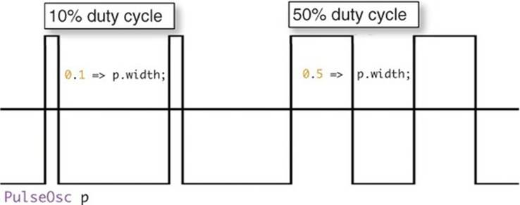
The 0.5 setting, also called 50% duty cycle, generates the same waveform that SqrOsc does. Such oscillators with varying pulse widths are commonly used in electronic dance music, often changing the pulse width in rhythm to the music. Sweeping the pulse width dynamically can make cool science-fiction sound effects as well.
The code in listing 6.3 generates a techno dance bass line, using a PulseOsc connected to the dac as a sound source. In the main infinite loop, you set the pulse width randomly between 0.01 (really spikey, therefore really bright sounding) and 0.5 (square, more mellow sounding). You also useMath.random2(0,1) to flip a coin, to determine one of two pitches for your pulse wave. The lower frequency of 84 Hz is close to a musical E2 (the lowest string on a guitar), and the frequency of 100 is close to the note G2 above that. To get rhythm, you switch your oscillator on and off every tenth of a second, on for 60 milliseconds (0.06 seconds) and off for 40 milliseconds (0.04 seconds).
Listing 6.3. Sci-fi techno dance bass line using the PulseOsc UGen
//PulsOsc for techno-bass, by ChucK Programmer, 2014
PulseOsc p => dac; // connect a new PulseOsc to dac
// infinite loop of sci-fi techno!
while (true)
{
Math.random2f(0.01,0.5) => p.width; // set random pulse width
if (Math.random2(0,1)) // pick a pitch randomly
{
84.0 => p.freq; // from one of
}
else
{
100.0 => p.freq; // two different pitches
}
1 => p.gain; // turn on oscillator
0.06 :: second => now; // hang out a bit
0.0 => p.gain; // turn off oscillator
0.04 :: second => now; // hang out a bit
}
6.3. Envelope (smooth slow function) unit generators
So far in your programs, to separate repeated notes or to make sounds with rhythm, you’ve turned your oscillators on and off by changing a gain somewhere in your sound chain. You set it to zero for silence and non-zero for sound making, switching between those to play individual notes. But most sounds and musical notes don’t work that way in nature: When you blow into a clarinet or trumpet, or start bowing a violin, or begin to sing, the notes don’t switch on instantly. When you stop blowing, bowing, or singing, you don’t hear a click because the sound stopped instantly. For most instruments, you can choose to start a note softly and get louder or start loud and get softer. There must be a better way to turn your notes on and off more gradually, and indeed there is.
Envelope UGens built into ChucK gradually ramp up and down to control volume or other parameters you might want to change slowly. The Envelope UGen ramps from 0.0 to 1.0 in response to a .keyOn message, over a time set by the .time method. The Envelope UGen ramps back to zero in response to a .keyOff message.
6.3.1. Making a clarinet sound using SqrOsc and Envelope
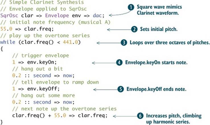
In chapter 1 we talked about how a square wave can sound somewhat like a clarinet and how the stick-slip physics of bowed strings generate something like a sawtooth wave. Now, by applying an Envelope to a SqrOsc, you can build a super-simple clarinet that more properly (gradually) starts and stops notes.
Listing 6.4 shows a simple example of using the Envelope and SqrOsc UGens to make a clarinet sound. Note that you connect the oscillator through the Envelope to the dac ![]() . After setting an initial frequency
. After setting an initial frequency ![]() , you use a while loop
, you use a while loop ![]() to play individual notes by triggering the Envelope
to play individual notes by triggering the Envelope ![]() , waiting a bit to let it smoothly rise, and then turning the Envelope off
, waiting a bit to let it smoothly rise, and then turning the Envelope off ![]() (again waiting a bit to let it ramp down). We use a loop to play what’s called a “harmonic series,” increasing the pitch by 55 Hz. each time
(again waiting a bit to let it ramp down). We use a loop to play what’s called a “harmonic series,” increasing the pitch by 55 Hz. each time ![]() .
.
Listing 6.4. Simple clarinet synthesis with Envelope applied to SqrOsc
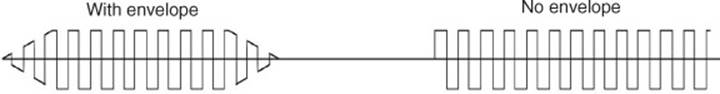
The left side of figure 6.2 shows the waveform generated by a single note of the code of listing 6.4. Note that the note starts and ends gradually, rather than switching on and off (shown for comparison on the right side of figure 6.2).
Figure 6.2. Envelope UGen applied to SqrOsc (left), compared to no Envelope (right)
There are other methods you can use with Envelope, such as causing it to move to an arbitrary target value in response to the .target message, or you can set the output immediately using the .value method. For example, 0.5 => env.target causes the envelope value to ramp to 0.5 (no matter what its current value) and stay there once the value of 0.5 is reached. Invoking 0.1 => env.value causes it to immediately begin putting out that value, forever, until a keyOn, keyOff, target, or a new value message is sent.
6.3.2. Making a violin sound with SawOsc and the ADSR Envelope UG
Moving to a new instrument model, if you wanted to make a violin-like sound, you could swap the square wave for a sawtooth oscillator in the previous example. But let’s do some more interesting things to make it sound even more like a bowed fiddle. Violinists tend to use specific gestures to attack the notes, often shown in their physical motions when playing. There’s a more advanced and useful type of envelope generator in ChucK, the ADSR (which stands for attack, decay, sustain, release). Figure 6.3 shows a typical function generated by an ADSR UGen, in this case with attack, decay, and release set to 0.1 seconds and sustain level set to 0.5. You can set all of those individually using the .attackTime, .decayTime, .sustainLevel, and .releaseTime methods/functions, or you could do it all by using the .set method like this:
Figure 6.3. ADSR envelope generator UGen output
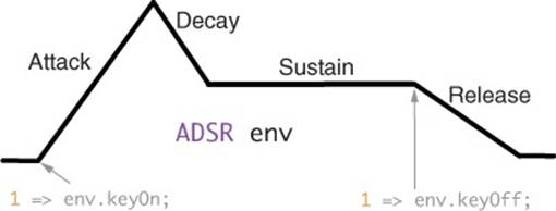
myEnv.set(0.1 :: second, 0.1 :: second, 0.5, 0.1 :: second);
Note in figure 6.3 that both decay and release took only half as long as the attack, even though their times were set to the same duration. This is because they have to go only half as far, from 1.0 to 0.5 for decay down to the sustain level and from 0.5 to 0.0 for the release phase.
To make your simple violin synthesizer, you can combine an ADSR envelope generator with a SawOsc, like this:
SawOsc viol => ADSR env => dac;
But there’s more to a violin sound than a sawtooth wave. Violins are famous for their vibrato, so you might want to do something about that as well. This is a perfect time to talk about a feature of the Oscillator UGens, and that’s that you can ChucK a signal into them to modulate things like frequency or phase. This is very good news indeed, because you can use a SinOsc to generate vibrato for your violin synthesizer, something like what’s shown in figure 6.4.
Figure 6.4. A simple violin patch uses sine wave vibrato oscillator, sawtooth oscillator, and ADSR.

SinOsc vibrato => SawOsc osc => ADSR env => dac;
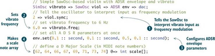
But that won’t exactly work yet, because you first need to tell your SawOsc to interpret the sine wave input as a frequency modulation. To do that you use the .sync() method ![]() , as shown in listing 6.5. And you need to set the frequency of your vibrato to something reasonable, like 6 Hz, using the .freq() method
, as shown in listing 6.5. And you need to set the frequency of your vibrato to something reasonable, like 6 Hz, using the .freq() method ![]() . You can set all envelope parameters at once
. You can set all envelope parameters at once ![]() , define a scale in an array
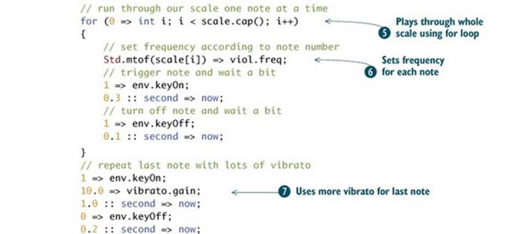
, define a scale in an array ![]() , and then play up that scale using a for loop
, and then play up that scale using a for loop ![]() , setting the pitch of the violin
, setting the pitch of the violin ![]() and playing each note using the ADSR. Finally, you increase the vibrato and play the last note longer
and playing each note using the ADSR. Finally, you increase the vibrato and play the last note longer ![]() .
.
Listing 6.5. Simple violin using SawOsc, Envelope, and SinOsc for vibrato
There are other oscillator types, including a whole family of GenX table generators, such as exponential, polynomial, line-segment, and UGens that automatically add together harmonic sine waves. All of these function as lookup tables (value in yields value out) but can also be used as oscillators by driving them with a special Phasor UGen. All of these, and more, are covered more in depth in appendix C.
6.4. Frequency modulation synthesis
If you set the frequency of the vibrato oscillator in figure 6.4 to much higher in the audio range, you’ll hear something quite odd. That’s exactly what happened to composer John Chowning at the Stanford Center for Computer Research in Music and Acoustics (CCRMA) when he typed in 100 instead of 10 for the frequency of a vibrato oscillator. He was using sine waves for both oscillators, but what he heard sounded a lot more interesting than just a wiggly sine wave or two. He asked around and discovered that what he was hearing was a complex spectrum created by frequency modulation (FM).
If you change the viol SawOsc oscillator in listing 6.5 to a SinOsc, set vibrato.freq to 100.0, and set the vibrato.gain to something larger, like 1000.0, you’ll hear something a lot like what Chowning heard in 1967. What you’re hearing is a whole bunch of sine frequencies that are created when the one wave (called the modulator) modulates the frequency of the other (called the carrier). One way to view this is that by changing the frequency of the carrier rapidly, the sine wave shape is distorted into a different shape. In fact, FM is part of a class of synthesis algorithms called wave shaping.
Now change the line inside the loop (![]() in listing 6.5 and repeated here) so that the viol and vibrato oscillators get set to the same frequency, and change the vibrato.gain so you get more modulation:
in listing 6.5 and repeated here) so that the viol and vibrato oscillators get set to the same frequency, and change the vibrato.gain so you get more modulation:
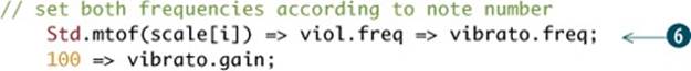
You’ll note that it sounds sort of like a brass instrument playing a scale. Now change the single line of ![]() to two lines:
to two lines:
// set carrier and modulator freq randomly
Math.random2f(300.0,1000.0) => viol.freq;
Math.random2f(300.0,1000.0) => vibrato.freq;
Run it a few times. You’ll notice that each note has a different character, generally inharmonic bell-like tones (but minus the decay characteristics that bells have).
Chowning worked out that if the carrier and modulator frequencies aren’t related by simple integer ratios (C:M ratio of 1:2, 2:1, 2:3, 1:3, ...), then the resulting spectrum will be inharmonic. He went on to synthesize bells, brass, voices, and other interesting sounds, all using just sine waves! Adding and combining more modulators and carriers can yield even more interesting sounds.
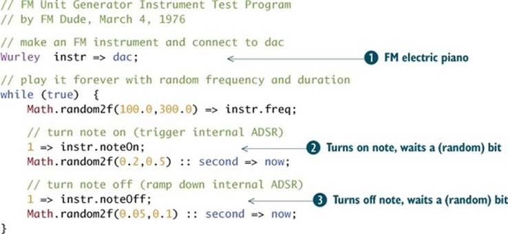
ChucK has a number of built-in FM UGens and presets for those to model the spectra of a variety of instruments, including electric pianos (Rhodey and Wurley). The following listing is a simple program for testing the Wurley electric piano.
Listing 6.6. Simple FM test program
Exercise
Other STK FM instruments include an organ (BeeThree), FMVoices, orchestra chimes (TubeBell), flute (PercFlut), and distorted guitar (HevyMetl). Switch out the Wurley UGen in ![]() for some of the others (TubeBell, PercFlut, Rhodey, and so on). Because these UGens are complete self-contained instruments, they respond to noteOn
for some of the others (TubeBell, PercFlut, Rhodey, and so on). Because these UGens are complete self-contained instruments, they respond to noteOn ![]() and noteOff
and noteOff ![]() messages, which turn on and off the internal ADSR envelope generators that control the levels of the internal carrier and modulator oscillators.
messages, which turn on and off the internal ADSR envelope generators that control the levels of the internal carrier and modulator oscillators.
6.5. Plucked string synthesis by physical modeling
It’s probably time to observe that the clarinet and violin you’ve built so far don’t sound very realistic, which might be fine for many purposes, but you can do better by looking at the physics involved in instruments like the clarinet, violin, and trombone. Physical modeling (PM) synthesis solves the equations of waves in and around sound-making objects to automatically generate the sounds. This differs greatly from what you’ve done so far, where you synthesized a waveform or noise of some type. In PM, you emphasize the physics of the instrument, with faith that the resulting waveform will come out right.
In this section, you’ll be building an increasingly realistic string model, starting with the absolute simplest model (an impulse-excited delay line, to model the pick sound traveling down and back along the string), then adding a better excitation (noise), then improving the delay line to allow for better tuning, and finally adding even more control over the pick excitation. Let’s begin with one of the first historical computer string models.
6.5.1. The simplest plucked string
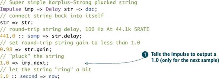
One of the earliest, most basic physical models for sound synthesis is that of a plucked string. The simplest version of this involves a delay line (a UGen that delays the signal from input to output, so that anything going in comes back out unmodified, but later in time), fed back into itself, and excited with an impulse as input. Of course, ChucK has all of these elements built in as UGens. This code shows the Impulse UGen fed into a delay line and then to the dac; then the delay line is hooked back up to itself to form a loop:
Impulse imp => Delay str => dac; // impulse feeds a delay line
str => str; // loop the delay back into itself
The Impulse UGen generates a single sample of output whenever you set its .next method to any value other than zero. That is, the line 1.0 => imp.next; ![]() in listing 6.7 causes imp to put out 1.0 on the next sample and then 0.0 forever after until you use the .next method again.
in listing 6.7 causes imp to put out 1.0 on the next sample and then 0.0 forever after until you use the .next method again.
Why is an impulse fed into a delay line and then fed back into itself a physical model? Because this sound chain is a valid physical simulation of a plucked string, where traveling waves move up and down along the string, with slight losses for each trip.
Synthesis history: physical modeling
The Plucked String synthesis algorithm (also called the Karplus-Strong algorithm) was discovered in 1982 by Stanford computer scientists Kevin Karplus and Alan Strong. That same year, Julius Smith and David Jaffe (an electrical engineer and a composer, working together at Stanford CCRMA) explained the model scientifically and improved it. Smith called the structure a “waveguide filter,” because the string (delay) guides the wave (impulse) back and forth along the string. Physical modeling synthesis is often called waveguide synthesis.
If you set the round-trip string gain to something less than 1.0 (to represent the slight losses) and set the string length (delay time) to some reasonable value for the round-trip time (the period of oscillation of the string), then you’ve built a primitive string model, as shown in the following listing.
Listing 6.7. Simple plucked string physical model
This makes a sound that’s vaguely string-like, in that it starts suddenly, decays more slowly, and has a pitch. But you can do better, by exciting the string with something more interesting than an impulse.
6.5.2. Exciting the plucked string with noise
The original plucked string model inventors actually excited (plucked) their string with noise rather than an impulse. This corresponds to a really energetic pluck, but it sounds bright and very cool. Fortunately, ChucK has a built-in Noise UGen, but it puts out noise constantly, unlike the Impulse, which spits out a pulse whenever you set the .next value. So you need to gate (switch on) the output of the Noise UGen to excite the delay line string when you pluck, then shut off the noise after a very short period of time. To do this, you can switch on the noise (set its gain to 1.0) for the number of samples equal to the length of the delay line, then switch it off (set the noise gain to 0.0), as shown in the next listing.
Listing 6.8. Better plucked string physical model, excited with noise
// Better Karplus-Strong plucked string
Noise pluck => Delay str => dac;
// hook string back into itself
str => str;
// round-trip string delay, 100 Hz At 44.1k SRATE
441.0 :: samp => str.delay;
// set round-trip string gain to less than 1.0
0.98 => str.gain;
// "pluck" the string for the right amount of time
1.0 => pluck.gain;
441.0 :: samp => now;
// shut off the noise generator
0.0 => pluck.gain;
// let the string "ring" a bit
5.0 :: second => now;
You need to do one more thing to copy what Karplus and Strong were doing, which will also make your simple plucked string sound even better. That is to add a filter in the string loop (delay line) to model the fact that the losses experienced by the waves traveling up and down the strings are frequency-dependent, where for each trip around the string, high frequencies experience more losses than low frequencies.
6.5.3. Modeling frequency-dependent decay with a filter
To model the frequency-dependent decay, you need only modify the line where you hook the string to itself by adding a low-pass filter, which reduces the gain of high frequencies more than low frequencies.
str => OneZero filter => str;
With this filter added, your string will instantly sound better and more realistic. OneZero is a very simple filter UGen, which we’ll talk more about very soon.
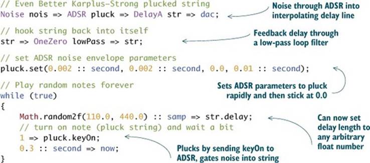
6.5.4. Modeling fractional (tuning) delay and adding an ADSR for plucking
You can also add one thing; the Delay line needs to support fractional samples of delay, so you can tune your string to arbitrary frequencies. Remember, in chapter 1 you learned that you needed floating-point numbers to express some pitches because integers wouldn’t do. For the string model, fractional delay is especially important for high frequencies, because the delay line gets pretty short and the difference between 44 samples and 45 samples at 44.1 kHz sample rate is 980 Hz versus 1002.27 Hz. If you needed exactly 995 Hz, then you’d need a delay of 44.3216 samples. Fortunately, ChucK has built-in interpolating delays, named DelayL (for linear interpolation between samples) and DelayA (for allpass, an odd type of filter that can yield fractional samples of delay). So all you’d have to do is replace Delay with DelayL or DelayA to enable fractional delay and thus arbitrary tuning. These delay UGens accept a floating-point number for delay, so you can set them to any length, such as this:
44.3216 :: samp => str.delay;
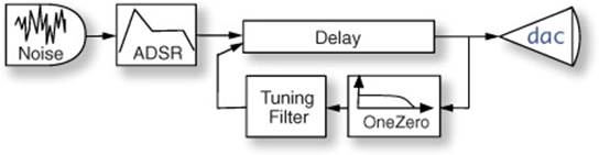
You can also use an ADSR to let your noise pluck into the string, which means you don’t have to turn it on and off explicitly. Once you’ve configured the attack, decay, sustain, and release parameters, you can use ADSR’s .keyOn method to accomplish your plucking. All of this is shown infigure 6.5 and the following listing.
Figure 6.5. Karplus-Strong plucked string model with noise pluck and loop filters
Listing 6.9. Even better plucked string, with enveloped noise and low-pass filter
6.6. Intro to filter UGens: frequency-dependent gain
What was that magic OneZero UGen you just used to provide the frequency-dependent gain in your string loop? The OneZero UGen uses simple math that adds its current input sample to its last input sample and divides the result by 2, thus computing an average of those samples. Another name for this filter is Moving Average.
(thisInput + lastInput) / 2 => output;
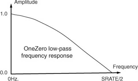
Averaging tends to smooth out rough signals, reducing high frequencies, while emphasizing smoother, lower-frequency signals. This is precisely what happens in a real stringed instrument as the waves travel down and back on the string. The frequency response of the OneZero UGen illustrated in figure 6.6, shows a gain of 1.0 for the lowest frequency (0.0 Hz), less gain for increasing frequencies, and a gain of 0.0 for the frequency at half the sample rate. This gain of zero at one frequency is the “one zero” in this filter name.
Figure 6.6. The OneZero moving average filter exhibits a simple low-pass frequency response.
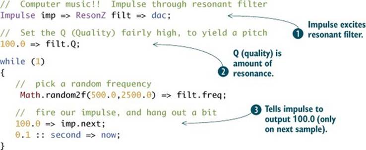
One other type of filter UGen we like to use a lot is ResonZ, shown in listing 6.10, which creates a single resonance (higher gain at one selectable frequency) on any signal passed through it. ResonZ responds to .freq, which sets the resonance frequency, and .Q, which stands for “quality factor” and determines the amount of emphasis at the resonant frequency. If you set .Q very high, ResonZ can oscillate as a sine wave; if you set .Q to 100 or so ![]() and feed the filter with an Impulse excitation
and feed the filter with an Impulse excitation ![]() , you get a pitched ping or pop sound at the resonance frequency each time you fire the impulse
, you get a pitched ping or pop sound at the resonance frequency each time you fire the impulse ![]() .
.
Listing 6.10. Simple resonant-filtered impulse makes for cool computer music
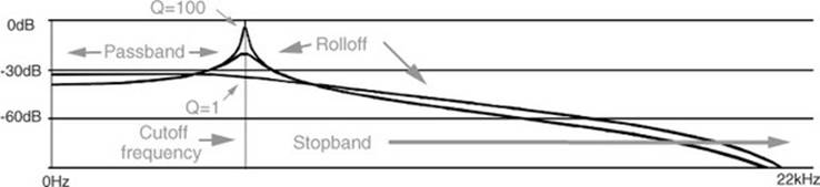
For shaping sounds and special effects, there are filter UGens for doing high-pass (HPF), low-pass (LPF), band-pass (BPF), and band-reject (BRF). These all are controlled using the .freq and .Q methods. The frequency range that can get through these filters is called the passband, and frequencies that receive decreased gain are called the stopband. The boundary between the passband and the stopband is called the cutoff frequency, which is set by the .freq method. Again, Q stands for “quality” and determines the amount of emphasis at the cutoff frequency and the rolloff (gain slope down into the stopband).
Figure 6.7 shows the frequency response (gain versus frequency) of an LPF unit generator, with Q set to 1, 10, and 100. Passband, stopband, and rolloff regions are labeled.
Figure 6.7. LPF low-pass filter frequency response for Q=1, Q=10, and Q=100
The following listing shows the use of the LPF (passes all frequencies below the cutoff set by the .freq method) UGen (resonant low-pass filter) to filter noise.
Listing 6.11. Testing the LPF resonant low pass filter with noise input
// pass noise through low pass filter
Noise nz => LPF lp => dac;
// set frequency and Q
500.0 => lp.freq;
100.0 => lp.Q;
0.2 => lp.gain;
second => now;
Exercise
Change LPF to HPF in listing 6.11. In the LPF case you should hear low frequencies up to the resonance frequency. In the HPF case you should hear high frequencies down to the resonance frequency. Try BPF and BRF. What do you hear? Change the .freq and .Q values and note how the sound changes.
6.7. More on delays: room acoustics and reverberation
When a sound is produced, the waves propagate (travel) outward from the sound source. Sounds made in rooms travel outward and bounce off the walls, floor, ceiling, and objects in the room (see figure 6.8). You might know that a single reflection of a sound off one boundary, such as a wall or building, is called an echo if the time delay is long enough for you to hear that reflected sound by itself (greater than 50 ms or so).
Figure 6.8. Sounds travel and bounce off (reflect from) walls before reaching your ears. If one of those reflections comes back significantly later in time, it’s called an echo. Lots of shorter time reflections from all the walls, ceiling, and floor combine to become reverberation.
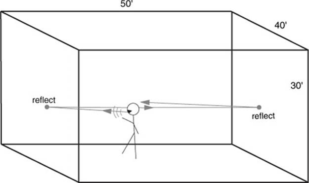
In a reasonable-size room, the reflections are shorter in time than echoes and add back together at the ears of a listener (or a microphone), to create reverberation. Because sound waves take time to travel, those trips around the room, bouncing off walls and other obstacles, take different times to eventually reach your ears (where all of the reflections add together). Remember when we were talking about the speed of sound, wavelengths, and stuff like that? Now that you know about Delay UGens, you can put all of that to work to make a simple model of the acoustics of a room. You’ll be able to feed any signal (like our microphone in through the adc) through this room acoustics patch and give it the sound of being in that room.
Let’s assume you want to model a room measuring 40-by-50 feet, with a 30-foot-high ceiling (figure 6.8). I know that’s a high ceiling, but the 3 x 4 x 5 dimensional trick is well known to designers of speakers, concert halls, and other acoustical things. If you assume the walls of your room are parallel and pretty reflective, then the path between each pair of parallel walls is much like our string that we developed in section 6.5.1 where waves travel back and forth, being reflected and absorbed a little each trip. Because you have three primary sound reflection paths, between the two pairs of walls and from the ceiling to the floor, you can use three delay lines to model the gross acoustics of your box-shaped room. The round-trip time between the wall pair spaced at 50 feet is 100 ms (an approximate rule of thumb of 1 ms per foot, and it’s a round trip, so 2 x 50 feet), the other wall pair delay would be 80 ms, and the ceiling/floor delay would be 60 ms.
The code in listing 6.12 creates a reverb (signal processing that models reverberation is often called a reverberator, or reverb) by connecting the adc through three delay lines, in parallel ![]() , and to the dac
, and to the dac ![]() . Then you connect each delay line back to itself
. Then you connect each delay line back to itself ![]() and set its gains to something reasonable of typical room dimensions and delays
and set its gains to something reasonable of typical room dimensions and delays ![]() . Then you must set the delay time for each delay. Delay times/lengths that use much memory (longer than a few dozen milliseconds) require you to tell the Delay UGen how long you expect it to be, so it can allocate memory. This is done using the .max method. You can set .max and .delay all in one line
. Then you must set the delay time for each delay. Delay times/lengths that use much memory (longer than a few dozen milliseconds) require you to tell the Delay UGen how long you expect it to be, so it can allocate memory. This is done using the .max method. You can set .max and .delay all in one line ![]() . Because you’re connecting the adc to the dac through some delays, be really careful about feedback (use headphones).
. Because you’re connecting the adc to the dac through some delays, be really careful about feedback (use headphones).
Listing 6.12. Simple reverb using three Delay UGens
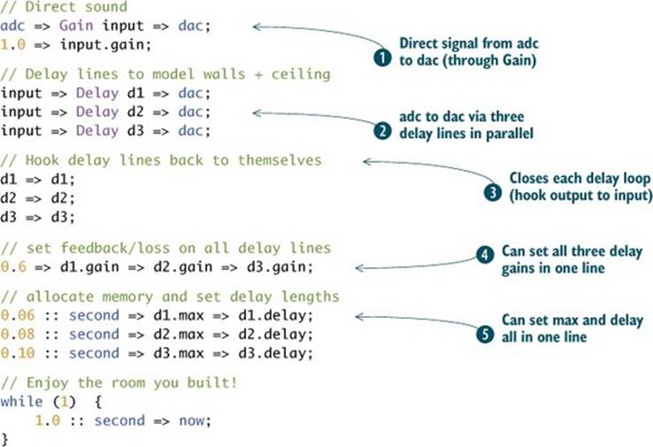
The results are pretty magical, but you might notice annoying ringing at a low pitch. That’s because 60, 80, and 100 ms all share some common factors, and those tend to pile up and cause resonances. This is easily fixed by changing the delay lengths to relatively prime (no common factors) numbers, like 61, 83, and 97 ms.
Assignment
Change the numbers to different values to see the effects. Change the delay gains from 0.6 to something else (but never greater than 1.0, because this causes sound to build infinitely). You’ll note that for smaller numbers, the reverb rings for less time, and for greater numbers, longer. This is called reverb time, and you get to control it because you’re a programmer! This reverb still sounds somewhat bright and ringy, but you could fix that by putting filters in the feedback loops just like you did with the plucked string. Try putting a simple OneZero low-pass filter in the loop of each delay where it connects to itself, like this: d1 => OneZero lp1 => d1;.
Okay, by now you’re thinking that designing and building reverberators that sound really good might be difficult. And it is, but once again you’re in luck, because ChucK has some built-in reverberator UGens: PRCRev (named after Perry R. Cook, who wrote it to be the most computationally efficient reverb that still sounds somewhat good), JCRev (named after John Chowning of FM fame), and NRev (N stands for New, which it was in the 1980s). These are really easy to use, as shown in the following listing.
Listing 6.13. Using ChucK’s built-in NRev reverberator UGen
// make a new reverb and hook it up
// (Again, Beware Feedback!
// Turn down the volume or wear headphones)
adc => NRev rev => dac;
// set reverb/dry mixture
0.05 => rev.mix;
// kick back and enjoy the space
while (1) {
1.0 :: second => now;
}
You might notice that this reverb sounds really nice compared to our three-delay one. That’s because it has lots of delay lines and filters, interconnected in ways that give it properties considered desirable for acoustic spaces. It was designed by really smart folks who know a great deal about simulating reverb, but you get to use it without worrying about all the inner workings. If you’re really into this type of thing, you could implement any reverberator of your choosing using ChucK. That’s the beauty of knowing how to program and having a powerful, expressive language.
6.8. Delay-based audio effects
From your experience so far with the plucked string, and with echoes and reverberation models using delays, you can see that delay line UGens do really well at modeling lots of interesting physical things. All of those delay lines were fixed in length once you set their initial delay. But interesting things also happen when delays vary in time. The Doppler pitch shift that happens when a car, train, or plane is moving toward or away from you happens because the delay time between the source and you is changing. So a delay line that changes length causes the pitch of what’s going through it to shift, upward if the delay is getting shorter and downward for elongating delay. You can exploit this to make a chorus effect, which uses delay lines that shift length slowly up and down to create delayed copies of any input signal, with slightly changing pitch. The pitch shifts up slightly while the delay is getting shorter and down while the delay is growing longer. And this all cycles slowly up and down. ChucK has a built in Chorus UGen, which you can use like this:
adc => Chorus chor => dac;
There are parameters you can play with for Chorus, such as .modFreq (rate at which the pitch is shifted up and down, the default is 0.25 Hz) and .modDepth (default is 0.5), and .mix (same function as in the reverberation UGens).
Exercise
Put a Chorus UGen into one of the examples from this chapter. Try it on the plucked strings, violin, Clarinet, Wurley, and so on.
If you wanted to constantly shorten a delay line in order to shift pitch up by some constant amount, you’d eventually run out of delay and reach 0.0. But if you made a bank of delay lines and cross faded (gradually faded in one delay while fading out another) between them as each one got too short, then you could make a pitch shifter. Well, ChucK has a UGen called PitShift that does exactly that. The next listing shows code that demonstrates how it works.
Listing 6.14. Using ChucK’s built-in pitch shifter UGen, PitShift
// run mic input through pitch shifter
adc => PitShift p => dac;
// set mix to all pitch shift (no dry signal)
1.0 => p.mix;
// forever shifting pitch
while (1)
{
// pick a random shift across +/- 1 octave
Math.random2f(0.5,2.0) => p.shift;
0.2 :: second => now;
}
We’ll introduce one more super-useful effect here called Dyno, for dynamics processor. Dyno has loads of features, including
· Limiting— Don’t let the signal get over a certain volume level.
· Compression— Make loud sounds softer and soft sounds louder, to yield a smaller dynamic range between loudest and softest.
· Noise-gating— Don’t let very soft sounds such as ambient/background noise through, but open up above some threshold and let louder sounds through.
· Ducking— Modify the level of the signal, but do it based on the loudness of some other, external signal.
Those of you who know about some of these effects will find the settings familiar, and you should look up all of them in the ChucK unit generator reference (appendix C). Even if you don’t know about compression, noise-gating, and ducking, one thing that Dyno is perfect for is protecting your ears and speakers. The compressor and limiter defaults are pretty good for doing that, because if the sound gets too loud, Dyno keeps it in check. Many ChucK programmers we know always put a Dyno before the dac in nearly every patch they make, especially experimental ones that they think might blow up, such as feedback. Using Dyno is, of course, as easy as this:
adc => Dyno safety => dac;
6.9. Example: fun with Filter and Delay UGens
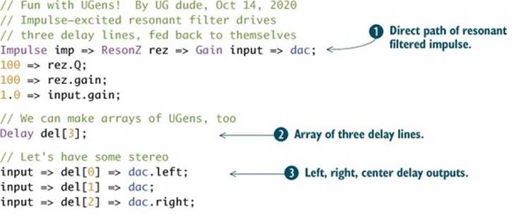
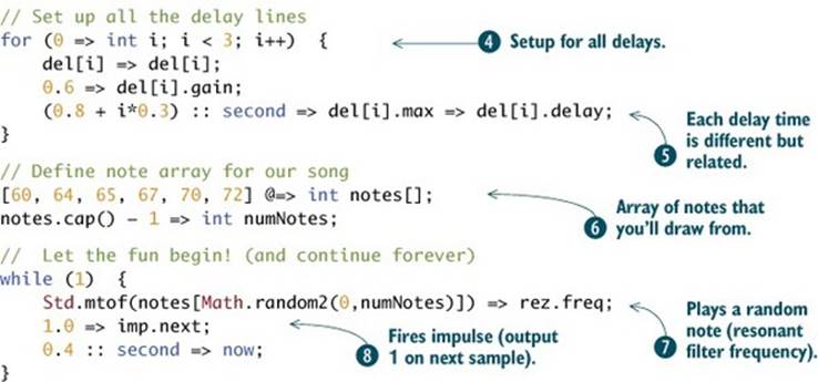
To use all you’ve learned in this chapter, we’ll finish up with an example that expands on our ResonZ UGen example from listing 6.10 and our three-delay UGen reverberator from listing 6.12. In listing 6.15, you use the same impulse UGen-excited ResonZ filter to give you pitched pings ![]() . Then you make an array of three Delay UGens
. Then you make an array of three Delay UGens ![]() (yep, you can make arrays of pretty much anything), and connect those between your input and the left, center, and right dac channels
(yep, you can make arrays of pretty much anything), and connect those between your input and the left, center, and right dac channels ![]() . You do the rest of the delay line connections, setting of delay times, and gains in a for loop
. You do the rest of the delay line connections, setting of delay times, and gains in a for loop ![]() . You make the delays quite long, on the order of a second or more, to create a multichannel stereo echo effect. If you look at the math in
. You make the delays quite long, on the order of a second or more, to create a multichannel stereo echo effect. If you look at the math in ![]() , you can work out that the three delay lines will be given delays of 0.8, 1.1, and 1.4 seconds. You then declare a MIDI note number array
, you can work out that the three delay lines will be given delays of 0.8, 1.1, and 1.4 seconds. You then declare a MIDI note number array ![]() that you’ll use to set the pitches of the ResonZ filter.
that you’ll use to set the pitches of the ResonZ filter.
After setting everything up, you drop into an infinite while loop, setting random pitches from the allowed notes of the table ![]() and firing the Impulse UGen to make sound
and firing the Impulse UGen to make sound ![]() . Note that there’s only one sound-producing object in this whole program (the Impulse), but interesting polyphonic (multisound) and rhythmic music results, because of the delay lines and their lengths.
. Note that there’s only one sound-producing object in this whole program (the Impulse), but interesting polyphonic (multisound) and rhythmic music results, because of the delay lines and their lengths.
Listing 6.15. Musical fun with a resonant filter and three delay lines
6.10. Summary
In this chapter you elevated your sound synthesis and processing abilities to a new level, by learning about a lot more ChucK unit generators. UGens are built into ChucK to make sound synthesis and processing easy. Important points to remember include:
· Envelope and ADSR UGens make slowly changing values to control volume and other things.
· You can generate sound by frequency modulation synthesis either from scratch, using one sine wave to modulate another, or using ChucK’s built-in FM UGens.
· Physical models, like the plucked string, can be implemented using Delay UGens and refined using filters, noise, and ADSR UGens.
· Delay lines can simulate echoes, reverberation, chorus effect, and pitch shifting.
· ChucK has lots of built in UGens to do many effects!
In the next chapter, you’ll meet (more of) the STK (Synthesis ToolKit) UGens, expanding your knowledge of ChucK’s instrument UGens, including a number of physical models, and other flexible and great sound synthesis models and instruments.