How a Computer Works (2015)
23. SCSI
Small Computer Systems Interface
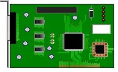
SCSI Controller Card
A faster way to move data between computer and hard drive is to use a SCSI (small computer system interface) connection. Typically IDE drive controllers transfer data at up to 5.5MB a second.
With 8-bit SCSI data is transferred at rate of 10MB-20MB a second.
Wide-SCSI incorporating a 16-bit data path transfers data as high as 40MB a second.
Too use SCSI on your computer a SCSI controller card is required which plugs into the motherboard.
SCSI Bus
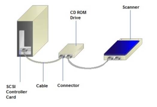
A single SCSI controller manages up to seven devices (some can run up to fifteen) like CD-ROM/DVD drives, printers, scanners and other peripherals.
These are connected through a daisy-chain connection.
We will describe how a SCSI controller card controls seven devices.
Each peripheral is connected on a daisy chain ribbon cable.
This is known as a SCSI bus.
Each device has a number between 0-6 to identify it.
Terminator
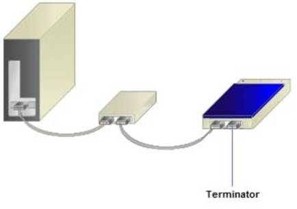
The SCSI card usually assigns the number 7 to itself. When a device is installed a number is assigned to it, either with software, or by manually setting switches.
A terminator is the last device on the chain.
The terminator grounds the cable wiring to stop electromagnetic fields from corrupting electronic data bits travelling through.
Initiator/Targets
Computer is initiator
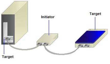
Disk drive is initiator
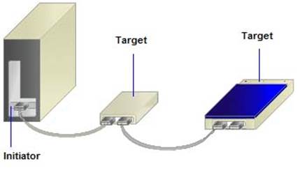
The SCSI bus consists of 50 wires in a cable. 8 lines are used to transmit data and a further line is used for parity checking. Wide -SCSI uses 16 lines, which boosts transfers up to 40MB a second. When Windows activates the SCSI controller card it becomes an initiator and the connected devices become targets. If a device starts communications then it becomes the initiator and the controller card becomes the target.
Arbitration Phase
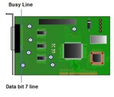

Busy and Data bit 7 line activate
To control the bus the controller waits for a pause in the message traffic and asserts control of the bus. The controller sends a voltage down the busy line and the line that carries the seventh bit of data.
This tells the bus the SCSI card wants to control the bus. During this process another device tries to control the bus; the bus goes into arbitration phase.
This process allows the device with the highest ID number to send a signal along the select line.

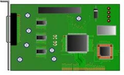
Attention line activate
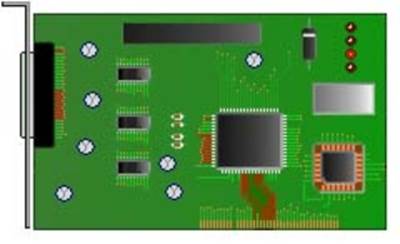
Request line activate
Reads in a block of data from a drive
In the selection phase the controller switches on the attention line and sends a signal to the device, for example a CD-ROM drive, it wishes to communicate with.
In return the CD-ROM switches on the request line. The controller acknowledges by placing a command descriptor block (CDB) on the data lines.
The controller switches on the acknowledge line. This tells the CD-ROM drive that the first CDB is waiting.
The CD-ROM drive then reads in the CDB and switches off the request line to tell the controller it received the data.
Data
The controller then switches off the acknowledge line to signal back the CD-ROMs acknowledgement. This exchange goes back and forth until all the data is transferred.