Computer Security Basics, 2nd Edition (2011)
Part IV. Other Types of Security
Chapter 10. Wireless Network Security
Wireless network communications, systems that interconnect several units without using wires, has been a goal of network administrators for a long time. This is because seasoned administrators know that sometimes wires just do not go where you need them to. Further, there has always been a need for mobility in computing. Wireless provides that. The need for portability has increased dramatically in recent years, however, probably to keep up with the cellular telephone, which has granted unparalleled flexibility to wandering users.
Unfortunately, wireless is based on a shared medium, called at one time “the Ether.” Because wireless communications work by injecting electromagnetic waves into the ether, everyone who can poke an antenna into the path of a radio wave can intercept a wireless transmission.
So, the question us, how do you maintain security over a medium that is without bounds? The answer is careful encryption, limited power, and attention to antenna placement. Although the folks at the neighborhood electronics store would have you believe that all you need to do is plug a card into your computer and you can join the wireless world, if you fail to pay attention to some basics, you are entering a threatening world in which your secrets are no longer your own.
How We Got Here
Before we talk about where wireless is and where it is going, let’s look at where it came from. Radio waves happen when electrons run down a wire, and the movement of current produces magnetic fields and electrostatic fields that ebb and flow with the current. Using that phenomenon to convey information is a matter of controlling the current changes and characteristics of this ebb and flow, a process called modulation. The names of two types of modulation can be seen on any radio dial: amplitude modulation (AM) increases and decreases the strength of the current to convey information. Frequency modulation (FM) changes the current’s frequency of oscillation. Additional ways to change or modulate the currents abound. Pulse modulation (PM) emits sharp bursts of current, carrying information in the timing of bursts. PM was the basis of early digital transmission systems, but today’s modulation methods are much more sophisticated. Without getting too lost in details, the modulation systems used in wireless today use combinations of these three to efficiently transmit digital information. Because these systems spread their information over wide sections of the radio spectrum, they are called spread spectrum systems. Because they vary their operating frequency rapidly, they are also called frequency hop systems. To understand too much more about them would require some serious arm waving discussion at a white board, or better yet, some military experience with the systems where these techniques were first used. For the purposes of this book, it is enough to know that the modulation systems used in wireless today can pack an amazing amount of information into a low-power signal. The result has been a proliferation of IEEE 802.11-type radio systems. Nearly any laptop purchased today has wireless connectivity built in. This is great, because it allows a computer to join the local area network without first having to string a wire to it. It has a number of security issues, however, which will be discussed in this chapter.
Today’s Wireless Infrastructure
Many network administrators and most home users have the belief that setting up a wireless network is a self-managing affair. Wireless cards are available for most computers. The thinking in many facilities today seems to be: “Throw in the wireless cards, and you are off.”
This is called an ad hoc infrastructure. Sure, wireless will work under these conditions but to do so is to invite a security disaster. In this arrangement, units attach freely to each other, and there is no central authority to govern authentication (see Figure 10-1).
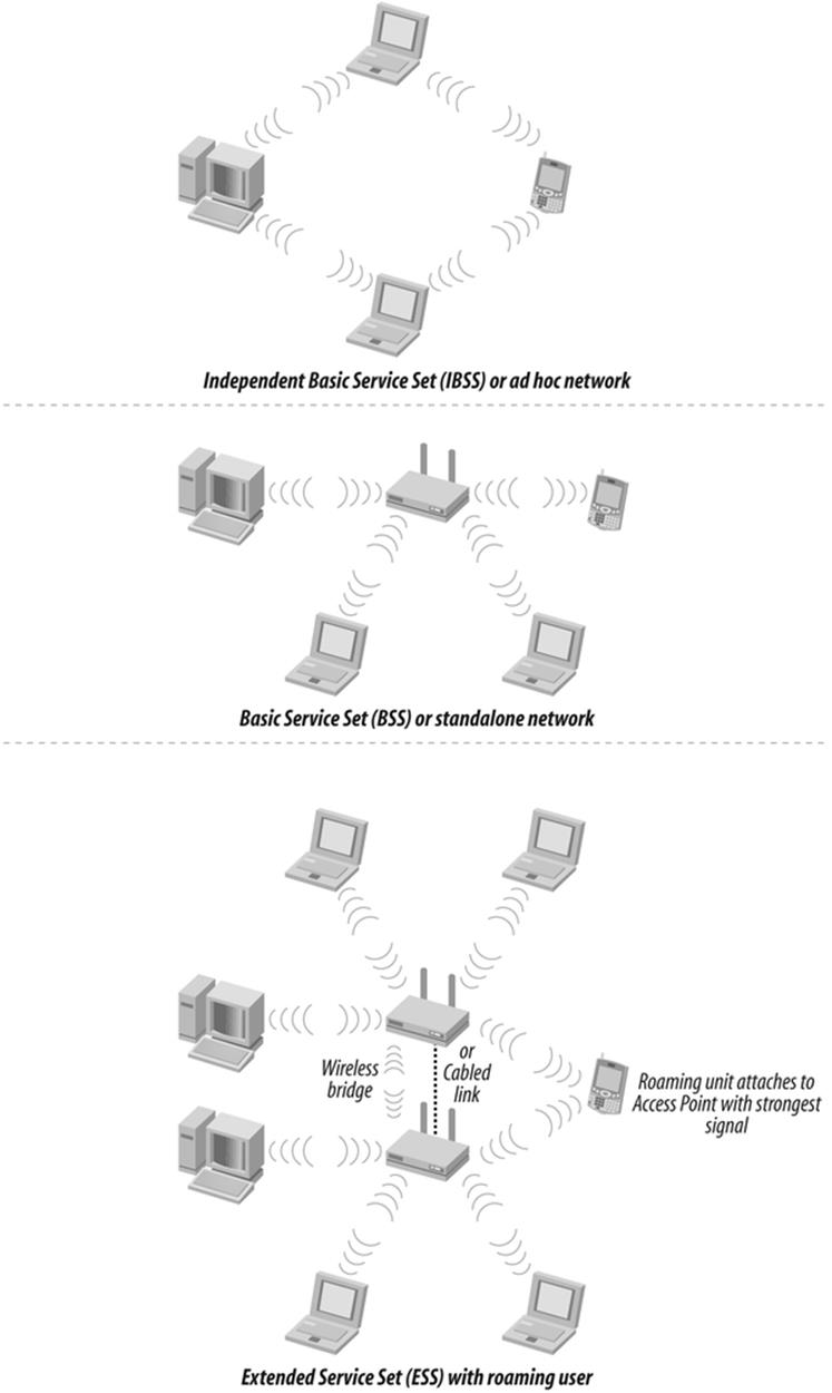
Figure 10-1. Wireless architectures
In contrast, an infrastructure architecture is a wireless network in which all units communicate with one unit that connects to a wired network. Wireless access points (APs) provide an interface between the physical network and the various computers containing wireless cards. This makes sense; after all, most people use wireless not to connect to each other, but to a LAN, or to the Internet.
Infrastructure architecture improves security and performance because administrators can monitor central login points to detect illicit access attempts. This architecture also makes network resources available to wireless users in the network, which increases the value of the connection.
Each network attachment point and the area it serves is called a basic service set (BSS). If it exists alone on a network, it is called an independent service set (ISS). Two or more basic service sets can exist on the same wired network. Traffic hands off between them depending on which has the stronger signal; this process is called roaming.
It is possible to take advantage of wireless to overcome an impassible barrier between two network segments. Used in this way, wireless equipment forms a network bridge. Most access points will function as bridges; however, if the interconnection is between two buildings, there may be an advantage to using specialized hardware that is optimized to withstand exposure to the elements.
Home users too have pined for the advantages of a wireless world. Even something as simple as working one’s laptop while watching a TV show used to require stringing a long network cable across the floor. This was a trip hazard at the least, and such a cable was often a luxury in its own right. Well-wired houses can be a rarity. The time and tools required to route wires through walls made it a daunting task. A wireless access point connected to a cable or DSL modem makes wireless highly desirable for home use.
Wireless Costs
Wireless was formerly an expensive and cumbersome solution. Until it became possible to lower its cost and increase its performance, wireless in data networking remained an expensive niche solution, justified only in a few unusual circumstances in which running cable simply was not feasible. These usually took the form of bridge links between buildings or floors.
With the adoption of the IEEE 802.11 series of standards in 1997 and subsequent updates, practical and easy wireless networks became available at reasonable cost. Wireless suddenly found a place in corporate networking and coffee shops, public places and poolsides. Anywhere you desired network computing without the necessity of running cables first, wireless hit the ground running. Although there are many forms of radio and light wave communications that can be called “wireless,” wireless systems, or Wi-Fi, usually refer to those that align with the 802.11 standards.
RADIO RUNDOWN (WIRELESS WORDS)
Standards for Wi-Fi communications systems are put forth by the IEEE and licensed by local governments. The IEEE 802.11 family of equipment operates in the unlicensed portions of the 2.4 GHz industrial-scientific-medical (ISM) band and 5 GHz unlicensed national information infrastructure (UNII) radio bands.
The original wireless, IEEE 802.11, an old 1-Mbps service, has largely been superceded by 802.11b, which operates at 11 Mbps on 2.4 GHz. The newer IEEE 802.11a system operates at 54 Mbps on 5 GHz. In June 2003, the IEEE 802.11g standard was formalized. This standard put the superior 802.11a transmission scheme onto the friendlier 802.11b frequencies, allowing 54 Mbps on 2.4 GHz as well, although most 802.11g units maintain backward compatibility to 802.11b, and multiband radios are available. The IEEE 802.11n standard offers increases in range and significant increases in speed over a, b, or g. The new IEEE 802.11i standard adds security to the 802.11 series, helping to plug a serious deficiency. Here are some other versions of radio communications:
Fixed microwave
Licensed channels link at various frequencies. The low-cost, license-free 802.11x systems are a direct response to the difficulty and expense of these services, but a license carries the advantage of legal protection against interfering services.
Multi-Channel Multipoint Distribution Service (MMDS) or “wireless cable”
This repurposing of terrestrial microwave channels, including the instructional television fixed service (ITFS), is used for schools.
Local Multipoint Distribution Service (LMDS)
A wireless competitor to fiber optic to the pedestal (FTTP), LMDS is a licensed service that operates in the 28-31 GHz band to carry voice, video, and high speed data communication.
Satellite
Commercial satellite data services have existed for years, often using very small aperture terminal (VSAT) antennas, which were precursors to the small antenna satellite systems available for homes. Satellite home video services usually offer a data capability as well.
IEEE 802.15 (Bluetooth) wireless personal area network (WPAN)
This system offers low complexity and low-power short-range connectivity for personal devices and peripherals. Many systems use Bluetooth to synchronize PDAs and their desktop computers.
IEEE 802.16 wireless metropolitan area network (wireless MAN or WiMAX)
These licensed and unlicensed broadband wireless access systems operate in a variety of frequencies as an alternative to fiber optic for last mile distribution to businesses.
Infrared
Infrared offers generally low bandwidth line of sight communications for control devices, such as TV remote controllers.
Free-space laser
These systems offer lightwave-based license free communications and are an alternative to fixed microwave.
There are real advantages to wireless. Without it, the work area outlet near your desk (the RJ-45 connector where you plug your computer in) is served by a consolidation point, which leads to a telecommunications room, where it ends on a patch panel before being wired into some kind of expensive equipment, such as a switch or router. This orderly structured cabling system is designed to be durable, reliable, and serviceable, but at a price of flexibility and spontaneity. It is literally built around a concept of servicing a work area, not a person. Different people may come and go, but the work area remains the same.
In contrast, wireless sort of just—well, connects. You loft a signal from your computer, and if you are within radio earshot of the access point, you are asked to authenticate (provide your username and password), and then you are on the air, or attached. You are connected at a speed of anywhere from one-half to about three times that of a 10BaseT (10 megabits per second) LAN, depending on the flavor of 802.11 used, and you can sit wherever you please and move about at will.
But wireless is fraught with dangers that come from not being tied to a cable. Unauthorized users can attempt to make connections in your name without having to set foot within your walls. If they get in on your radios, they can use up bandwidth, access files without proper identification, and potentially gain a free rein on your network and beyond. Wireless provides a modern-day version of the old problem of users installing unauthorized modems on their desktop PCs. And regardless of whether they can actually attach to your network, they can still eavesdrop freely without making a connection, something that is difficult, though not impossible, to do with wired networks. That is the trade off of wireless; you can get high speed and easy connection with great ease—but so can everybody else.
TOO FREE ACCESS?
I was once on a job site in a large office park where a local affiliate of a large chain was replacing their main data link to the corporate offices in the East. The plan was to connect two wireless access points to a router, which connected via a T-1 link to the corporate headquarters. A firewall was employed to keep outsiders out. Because of a glitch in the service provider’s programming, we could not turn on our system and provide service as planned. After an hour or so, the provider corrected the issue. We then went to apologize to the branch president, who had anticipated using his new wireless laptop card to browse the Internet over lunch. His response was a lecture in wireless security packed into one sentence. “Is there something wrong?” he asked. Although our own system was down, he had not missed a beat. There were enough carelessly secured wireless access points operating in the surrounding businesses that he never lacked connectivity. Good for browsing, but bad for those businesses.
How Wireless Works
When a magician suspends an assistant in thin air, it has a way of getting the audience’s attention. There is something counterintuitive about seeing someone apparently defy the law of gravity when you spend your entire life learning to obey it.
Wireless is like that. It follows its own rules and conforms to its own logic. A top-rated world-class antenna engineer once confided to a friend of mine, a lowly Navy technician at that time, that he really didn’t truly understand how antenna systems actually worked, and doubted if anybody did. However, that didn’t permit him to give up and change jobs: people were depending on him. He had to stick with it, even when in his heart of hearts, he knew that much of his success was by luck.
Fortunately, while the advanced parts of wireless are sheer mystery, the basic bits are understandable enough, once you’ve been properly introduced. If you know this, you will be prepared to deal with an emerging round of hacks and countermeasures. Just as the script kiddies don’t usually have a clue how things work, many wireless crackers will be just as in the dark. If you know what is actually taking place, you will be better able to outwit them. We will now look at wireless security starting with the business end, the radios and antennas.
Both wired and wireless network communications work on the same principles. When electrons flow through a wire, they cause the creation of electromagnetic fields around the cable, as you can see in Figure 10-2.
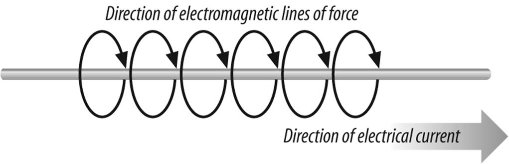
Figure 10-2. Creation of electromagnetic field around cable
If you now shoot a current flow into a cable that does not connect to anything, but simply ends, the electrons of the current flow tend to accumulate until they reach a charge equal to or exceeding whatever force propelled them down the cable in the first place.
At this point, the accumulated charge starts to swim back upstream towards the source and may even oscillate back and forth a few times until the charge ends up evenly spread over the length of the conductor. If the exciting voltage is pulsed or alternated in polarity, it becomes possible to set up a pattern of waves in the conductor as charges are pushed to the end of the wire and bounce back. As the electrons surge back and forth, the electrical and magnetic field surrounding the wire ebbs and flows as well. (See Figure 10-3.)
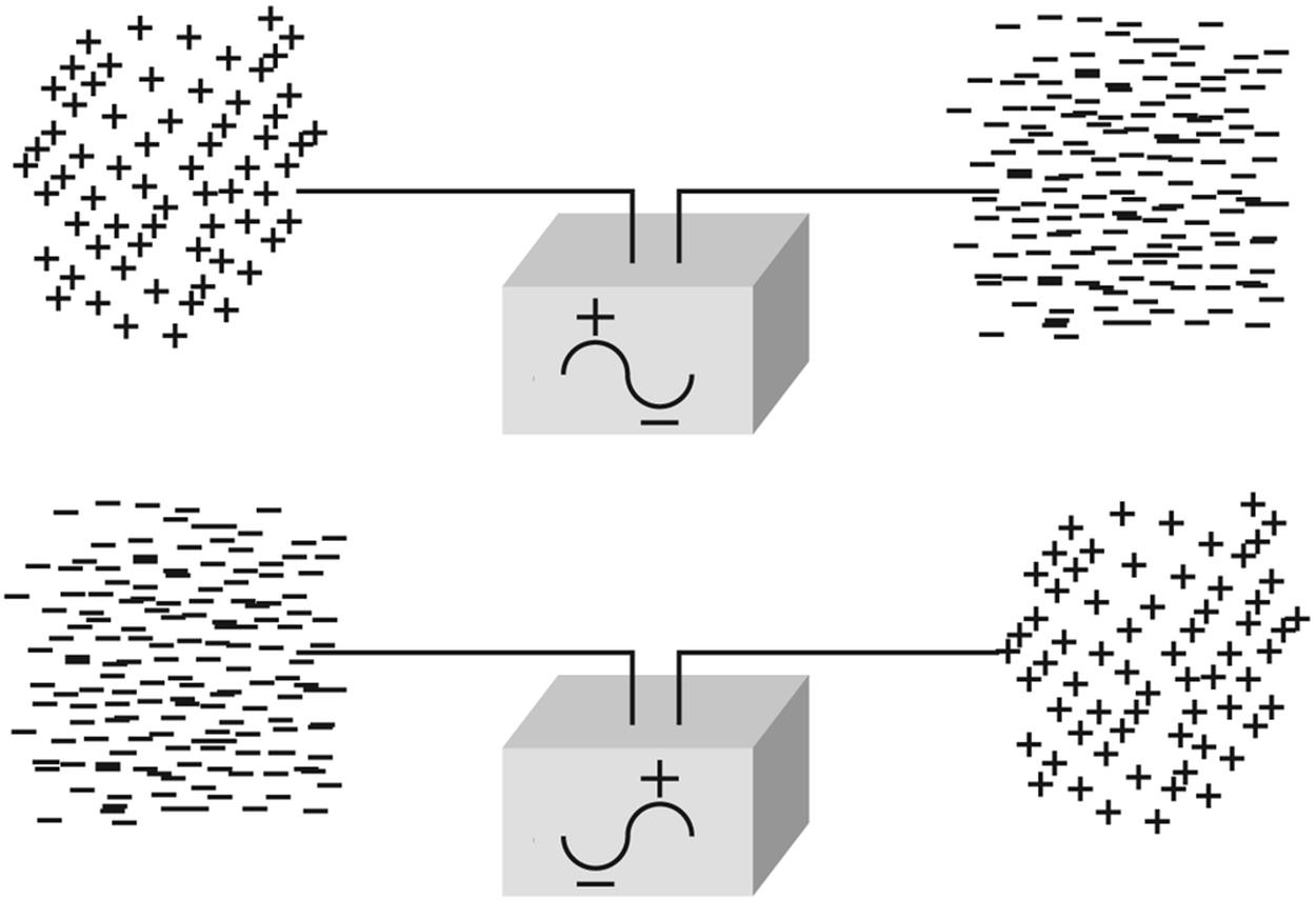
Figure 10-3. Accumulation of charge at the end of an unterminated piece of cable
If you adjust the length of the wire, which is called an antenna, to a length that is just right, a launch effect occurs (see Figure 10-4). The electric fields essentially step off the wire and travel through the fabric of space, theoretically going forever, except they decrease in power or intensity with the square of the distance from the launch point.
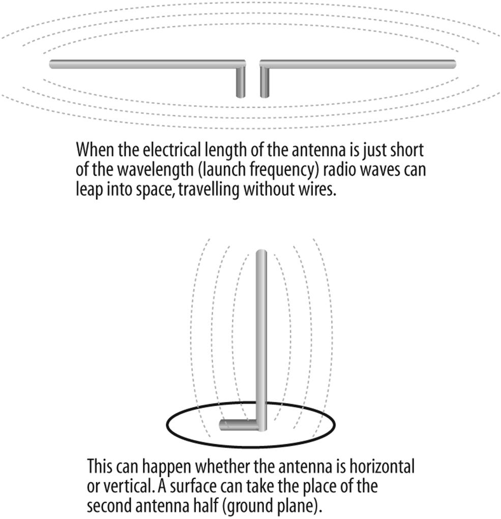
Figure 10-4. Cut to the correct length, the wire becomes an antenna and launches electromagnetic waves into space
In the period of just over a century that this effect has been recognized, people have learned much about how to control it and put it to good use. For instance, early on it was discovered that the orientation of the antenna at launch determined the orientation of the wave as it traveled through space. For convenience, these orientations are called horizontal polarization and vertical polarization, although many other combinations are possible, including circular and elliptical polarizations, and even mysterious shifting polarizations used for some radars, that appear to have the ability to hide radiation. (Radio waves are a form of nonionization radiation.)
A horizontally oriented transmitting antenna will be most effective if it is received by a horizontally oriented receive antenna, and will be least effective when received by a vertically oriented one. Understanding antenna polarity and knowing that radio waves sometimes change polarity as they pass through or bounce off of various materials and structures helps explain how sometimes shifting the antenna orientation just a little can dramatically improve the performance of an antenna system—or the ability to better reject certain interference (see Figure 10-5).
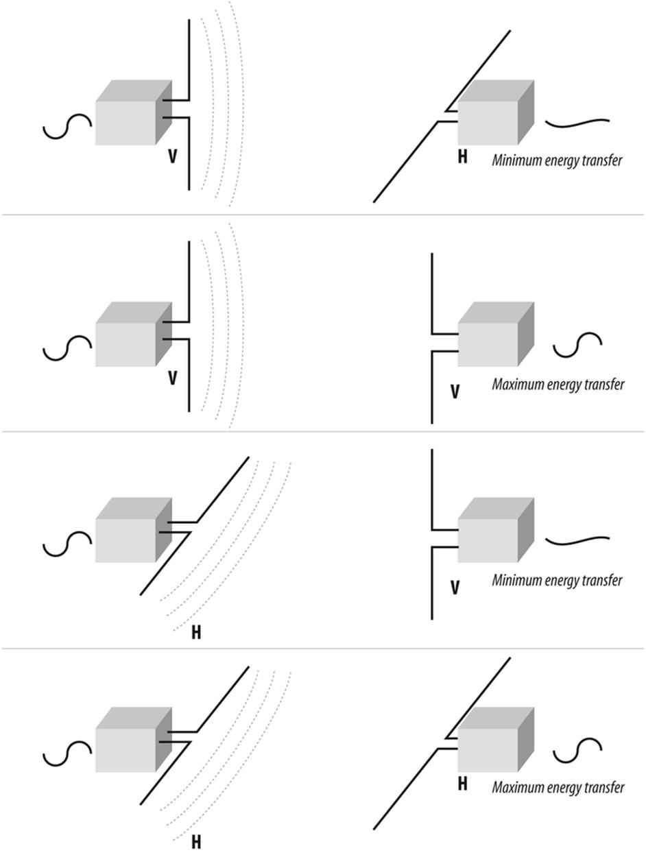
Figure 10-5. Observing correct polarity can help maximize antenna performance
Playing the Fields
One of the cardinal rules for installing a wireless system is to overcome the notion that antenna wire is simply a path for electricity. Coaxial cable is a mechanically precise system that must be gently handled if it is to perform well over time. Consider: the wire from your battery to the starter in your car is designed to move electrons. The power cord from the wall to your computer is designed to move electrons as well. At frequencies below a hundred cycles per second or so (hertz, or Hz), the efficiency with which cables pass their signals is determined by the thickness of the cable. Literally, the more copper, the more current the wire can carry. Above a couple of hundred Hz, however, the electrons begin to travel closer to the outer edge of the cable, due to a process called skin effect. By the time the frequencies approach that of LANs, most of the current is traveling on the surface of the wire, not the center. In the range of microwaves and radars, (which is roughly the same frequency as 802.11x) so much of the current travels on the surface that sometimes signals are routed through pipes called waveguides instead of wires.
What this means is that you must be gentle while installing cables and mount them in a way that supports them without stressing them. The condition of the surface of the wire is the highway the electric fields travel over. Don’t create potholes by mishandling the cable. The condition of the cable once it is in place, and the ability for it to resist damage as it sags and settles over the years, is what separates a good installation from a mediocre one. Good installers never nick a cable, never bend it tighter than four times the cable radius—even while installing it—and do not exert a lot of pressure while pulling it into place. This is even more important with the relatively low-power transmitters used in wireless.
Keeping the Waves Inside
To further explore the importance of electrical fields as they apply to security requires us to get a little more familiar with this invisible phenomenon. The patterns of the waves that emanate from antennas create a field pattern that can be measured and plotted. If we choose the length and orientation of our antenna carefully, we can make the fields that radiate from it interact in ways that shape that antenna’s sensitivity and pattern of coverage.
For instance, if we energize a simple vertical antenna, we create a pattern of energy that extends around it like a doughnut. (Well, maybe a flattened doughnut.) Interestingly, if we lengthen the vertical antenna, we flatten the doughnut some more; this is because the fields tend to interact (seeFigure 10-6).
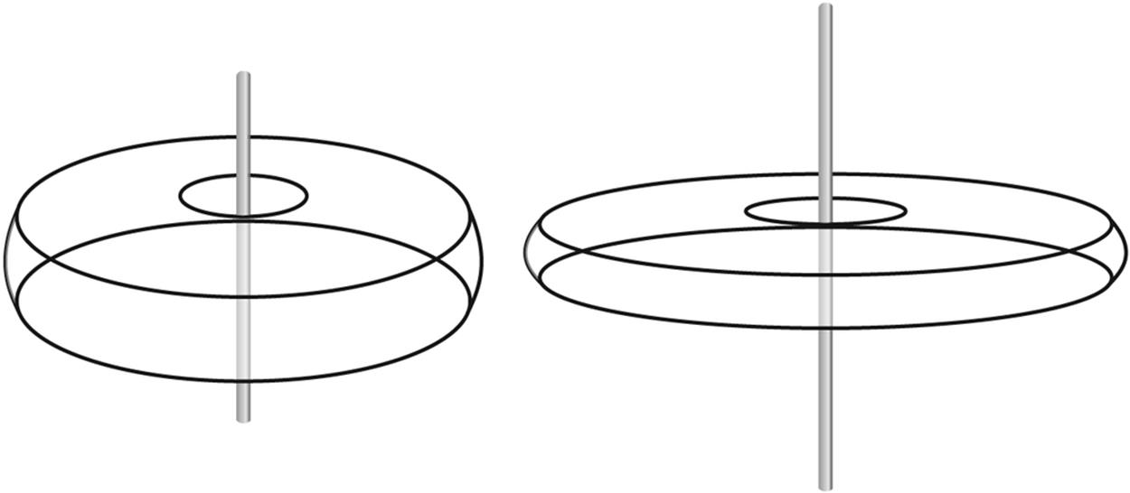
Figure 10-6. A vertical antenna radiation pattern where the doughnut’s width depends on the antenna length
Besides just squishing doughnuts, this interaction can be used to make an antenna directional. Let’s add a second vertical antenna of identical dimension and distance from the first (that is, we will keep the wires to each antenna the same length). If we space the two antennas at some multiple of one wavelength from each other (wavelength is the physical length of the one complete cycle of our fields), something interesting happens. The waves from the first antenna will arrive at the second antenna in phase, that is, at the same part of the electrical cycle. For this reason they will add together in their travels, nearly doubling the strength along the line of the two antennas. Perpendicular to that line, however, the waves conflict with each other, nulling out the signal. The resulting antenna pattern, therefore, is highly directional (see Figure 10-7). For the record, it doubles the strength along the main axis, providing an apparent six-decibel (6 db) gain, or roughly four times the power.
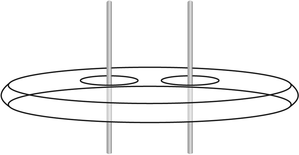
Figure 10-7. Spacing two vertical antennas one wavelength apart provides a signal gain along the line of the antennas
On the other hand, if we space the antennas at some multiple of a half wavelength apart, energy from one antenna will arrive at the other antenna out of phase. Instead of adding, the signals in the line of the two antennas cancel. The signals are increased, however, along the line formed between the antennas. The resulting pattern is wider than the pattern at the full-wave spacing, but not as long, because the antennas interact over a broader area. This half wave separation forms a pattern that is about half as strong, or about 3 db.
We can back-stop the two vertical antennas with a large piece of metal to form a panel antenna. This antenna uses the backing plate to reflect some of the energy back toward the two antennas and also prevents energy from passing through the barrier presented by the plate. The result is a pattern that has a large forward pattern, but has a dead spot behind. This kind of antenna would probably produce a gain of about 5 db. Panel antennas (see Figure 10-8) are usually wall mounted, and are used to project a signal forward into the work area, not backward into the parking lot, where it can be intercepted by sneaks.
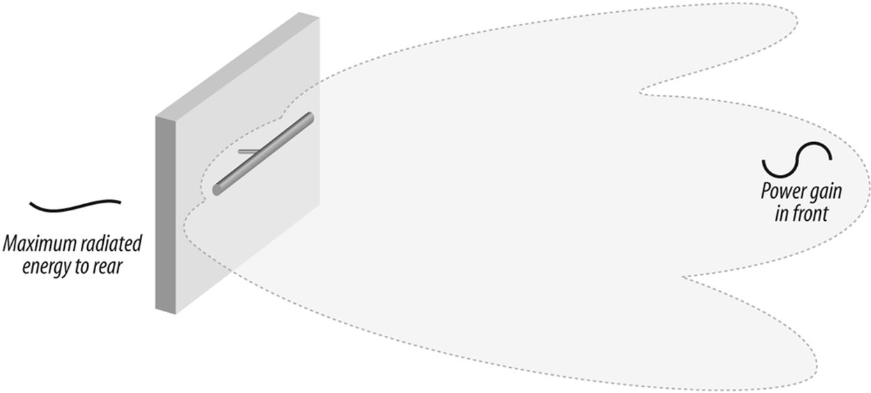
Figure 10-8. A panel antenna offers a wide, compressed unidirectional pattern
Adding an extra antenna element behind the radiating element that is slightly longer than the radiator creates a reflector. Adding elements in front of the radiator that are slightly shorter than the radiator creates a director. A reflector and one or more directors creates a very directional antenna called a Yagi, after the last name of its inventor. Yagis are very popular in wireless today. The gain of a Yagi increases with the number of elements, but 15 dB is not uncommon.
Finally, placing the radiator in front of a parabolic dish creates an antenna called a parabolic reflector or dish. The dish antenna is likely the most highly directional antenna available today, with the exception of antennas designed specifically for scanning and hacking. A dish can produce a gain of about 21 dB.
Using the manufacturer’s data sheets (see Figure 10-9), it is possible to tailor an antenna system that will fully cover or illuminate the desired areas of a floor or department, while minimizing the amount of energy leaving the building.
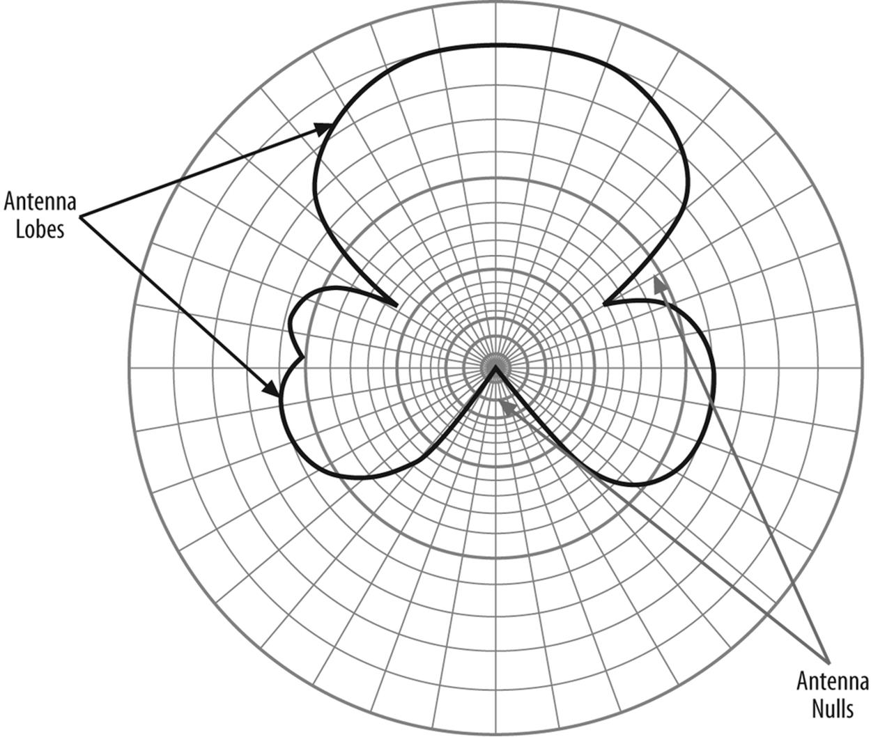
Figure 10-9. Antenna data sheets include charts that outline the antenna pattern
What Is This dB Stuff?
The theoretically plain vanilla, no-padded-seat, economy class antenna is the simple dipole. It is considered to add no increase to the power of the transmitter, hence it is a unity gain antenna. Unfortunately, it is easier to mathematically create a unity gain antenna than it is to construct one, so this antenna is usually theoretical, and it is called an isotropic radiator. This is a useful concept in wireless, because if we build a real antenna and measure its performance, we can express its performance and radiation pattern in terms of the amount of power higher or lower than the theoretical antenna. This information is usually plotted on some kind of graph that shows where the signal strength is greatest and weakest.
One decibel (dB) is a tenth of the power of whatever you start with, either added or subtracted. Because of the way things multiply out, each 3 dB increase in power is a doubling of power with respect to the isotropic antenna (technically 3dBi, where i stands for isotropic). Thus a dish antenna offering 21 dBi in the zone along its focus offers over a hundred times the power of the simple isotropic antenna. This multiplying factor is called antenna gain. A Pringles can Wi-Fi antenna (that’s right, an antenna manufactured out of an empty potato chip container), if kept dry, will have a gain of 8-12 dBi.
Why Does All This Matter?
Wireless is currently in a honeymoon period. People are throwing access points on the air with abandon, showing little regard for careful design. An emerging tenet of wireless administration, however, is that you should not illuminate areas you don’t intend to service. Splashed-over signal into the parking lot creates an inadvertent hot zone that attackers can take advantage of. Also, it is an emerging tenet that you should not accept logins from signals that are lower than a certain power level (as would occur if you log in from the park bench across the street) or that cannot operate at a link speed below a certain threshold (as would occur if you were an outsider trying to log in from a distance, say the parking lot). Carefully choosing the type of antennas to use and planning their physical layout so as to not splash out of bounds, will keep the radio energy where it is needed, minimizing interference from competing sources. This forms a first line of defense against external attackers seeking to eavesdrop or join in a network where they are uninvited. More about this in a moment.
Encouraging Diversity
There is one more principle that you should know about because it shows up over and over again in wireless. The electrical field of a radio signal, which is called the electrostatic vector, pulses alternately strong and weak. This is an artifact of the flow of charges that lead to its creation and launch into space from its antenna. At a rate equal to its frequency, the electrical vector starts out positive, moves through zero (at the zero crossing), goes negative, and returns to positive. At the same time, there is an electromagnetic field, or vector, which is a result of the antenna’s moving charge (remember, as current flows, it produces a magnetic field). This flows in a manner just opposite to the electrostatic, so that when the electrostatic vector is the strongest, the electromagnetic is the weakest, and vice versa. Let’s ignore this electromagnetic field for present, but it will come up again when we discuss advanced systems of eavesdropping.
Think for a moment about receiving a signal. Signals bounce as they travel, a condition called multipath. It is possible that any two paths of propagation will overlap, and the distances between the paths will be different enough that the signals null each other out (similar to what happens in a twisted pair cable). On the other hand, about a quarter wavelength away, the two signals are likely to be in phase, making the signal at that point twice as strong. If we place two antennas approximately one quarter wavelength from each other, the signal received at one of them will be at its peak energy while at the other it will be at zero. If there was only one antenna, and it was located at the null point, it might not be able to detect the signal at all.
Because of the extremely small wavelengths of the frequencies we are dealing with (they are after all microwaves) spacing the antennas about four inches apart usually ensures that one or the other or both will always be in signal, and sure enough, many access points use dual antennas at about this spacing. In the roving environment of wireless, the chances that a multipath will occur as the users move with respect to each other is just about certain. Using two or more antennas spaced a quarter wavelength apart to avoid loosing the connection is called diversity reception.
Physical Layer Wireless Attacks
The nature of wireless networks and their infrastructure lays the groundwork for a set of attacks that can be mystifying because they operate on different principles than many network administrators are used to dealing with. Each has a defense, and if it is left undefended, it becomes a future watch point for security administrators.
Hardening Wireless Access Points
Of course, the first attack is no mystery: steal the access point. I have seen access points mounted on walls at just above head height, just below the suspended ceiling. In many cases, they mount by two screws that click in to the back of the unit. If someone removes the unit, she creates a denial of service attack for any users that normally associate with that point.
This attack is effective because, for whatever reason, network administrators are at the time of this writing failing to take seriously the concepts of structured cabling as they apply to wireless. No one interested in maintaining their employment would leave a server, switch, or hub, in an exposed physical location. To do so defies the ANSI/TIA/EIA standard 569A regarding telecommunications pathways and spaces. This standard states clearly that telecommunications equipment rooms (formerly called wiring closets) are to be equipped with doors that lock. Cable runs are also in the preview of paths and spaces, so keeping the wires out of harm’s way makes sense; the same warning applies to access points.
A wireless installation that can be effective involves mounting a locking enclosure from the ceiling, and suspending it to align with the suspended ceiling. The cover to the enclosure, usually hinged to allow maintenance access, should be equipped with holes that allow the antennas to protrude down into the work area.
The cost of the enclosure shown in Figure 10-10 is likely several times the price of most access points available from consumer electronics stores. Add the cost of the installation (the enclosure must be suspended from the deck above the suspended ceiling, similar to a large florescent light fixture), and possibly the cost of an electrician to bring power to it, and it may become an overwhelming proposition for all but the most serious installations. However, it is often feasible to mount the access point on a wall just above the suspended ceiling. In this way the access point is secured by obscurity. Those who remember back to the days of ThickNet, which also ran above suspended ceilings, can guess what comes next. Do not allow service technicians to remove the suspended ceiling tiles with dirty hands, or at least make sure they lift them with the knuckles instead of the fings. If not, soon, the location of the access point will become obvious by the accumulated fingerprints.
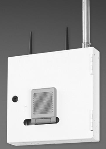
Figure 10-10. A reasonably secure wireless access point that conforms to network wiring standards
By the way, do not consider borrowing some electricity from a nearby florescent light. Most modern buildings operate their lights off a higher voltage circuit than what serves the electrical outlets. The higher voltage is more efficient for lighting, but could be disasterous for equipment. Electricians are paid to deal with things that spark. Use them.
Those who wish to discrupt your network, however, know that denying power to an access point is an excellent attack, one that will just about guarantee that the wireless part of the network will shut down. In most buildings, the servers and switches are, or should be, on UPS or backup power. Any laptops attached to the access points will be capable of operating on batteries. The weak link will be the access point, and a failure to protect it may indicate that you did not do enough planning for contingencies.
Securely providing power to an access point is actually a simple matter. There are several products that feature the ability to use Power over Ethernet. PoE works because there are four pairs of wires in an Ethernet cable, but only two are required for most communications at the speed that will serve an access point. The unused pairs carry power to the AP.
Back in the telecommunications room, either the switch feeding the AP is equipped to provide PoE, or the cable is run through a small device that inserts power on the cable. Devices in the telecommunications rooms have the opportunity to use protected power, that is, power that will continue after normal power is gone. This has the potential of making the wireless portion of the network even more robust than the wired section in some cases, because the desktop PCs and possibly even the telephones are likely to use unprotected power.
An alternative approach may be one of several systems that put Ethernet over power lines. The advantage is that two wiring systems, one for data and one for power, are not required. The security aspects of this system are not yet fully explored. In theory, the signals could leave the home or building and be available for interception.
The Tie That Binds
Although stealing an access point is a feasible attack, it leaves the attacker with the problem of having to carry off the unit, and then to dispose of it. It might be attractive to collect various units, but as long as they exist, they are evidence. A more reasonable attack is to simply cut the wires. If the access point is mounted on a wall in a hallway, this can be accomplished with any cutting tool. If PoE is employed, the attacker will likely use a pair of insulated grip wire cutters the second time he tries it because most systems use -48 volts, a telephone company standard.
Conduit or a flexible metallic “whip” can prevent an assault on cabling; however, installation may be costly and, to be truly effective, you may need to modify the case of the access point. A simpler solution again may be to mount the access point above the suspended ceiling. In this case, PoE is highly desirable because appropriate electrical outlets may be hard to find up there. Many facilities run all of their telecommunications wiring above ceilings, which leads to some important considerations:
§ If the area above the ceiling is used as an air return for the HVAC system, that space is known as a plenum. Electrical codes require the use of plenum-rated cables, which are jacketed with materials that will not give off poisonous gas when heated by a fire. These gases could threaten people in other areas of the building because of the shared air handling.
§ If you need to get through a wall that extends from the floor to the ceiling, don’t just poke a hole: it could be a firewall. A firewall is designed to seal off smoke and fire for a specified period, giving rescue and salvage workers a chance to work in unaffected areas. Poking a hole in that wall may violate its fire rating, and fire marshals and building inspectors get all excited about that, as do building owners, because it may have insurance ramifications. If you absolutely must go through that wall, look for an existing penetration and try to join it without disturbing the packing and putties that are part of a firewall penetration. Contact a telecommunications wiring specialist if there is any doubt or if you must unavoidably make a penetration.
§ Once it was common to lay cables on top of the suspended ceiling grid. Standards no longer allow this because the metal of the grid can bend the cables tighter than their minimum bend radius and affect performance. ANSI/TIA/EIA-569-A specifies that cable above suspended ceilings must be supported using an independent system of approved devices. That means you cannot use nylon cable ties to suspend network cables on the wires that hang the lights or the ceiling grid, or tie up to a pipe or electrical conduit. But I won’t tell.
On the chance that there is no way to avoid hanging an access point on a wall in an exposed area, at least take this simple precaution: run the wire from the telecommunications room to the wall, and terminate it in a wall-mounted jack. Then, use a short patch cord to go from the jack to the access point. This way, if an attacker tries to damage your network by cutting the cable, you can easily replace the patch cord with one of the spares that you keep in your desk drawer. The installation will then adhere to standards. It is also far easier than trying to install a modular 8-pin connector while perched on a stepladder.
Sophisticated Physical Layer Attacks
A more sophisticated physical-layer denial of service attack involves disturbing the medium, which in this case are radio waves. The classic attack is to overwhelm the receiver with noise, a process called jamming. Any generator of radio frequencies (RFs) in the 2.4-GHz region for 802.11b and 802.11g, and the 5-Ghz region for 802.11a, will suffice. As many surprised owners can tell you, DECT phones, Bluetooth devices, and cordless telephones, can (all in some cases) present jamming signals.
A steady jamming signal would be fairly easy to track down using a directional antenna and a laptop set up to do a site survey. This would be an effective attack, because it would require a sophisticated user to track down the jamming source. Much more devious and hard to trace, however, would be an attack that misuses some principle of the medium itself, for instance, the diversity reception system that is designed to prevent fading as users change their position with respect to each other. As explained previously, due to the wavelengths and the interference patterns involved, sometimes one antenna will have all of the signal, and the other will have none. However, most of the time, both antennas will have a portion of the signal. An effective DoS attack, then, would switch signals from one antenna to the other by introducing one that is stronger, yet invalid, on one of the diversity receive antenna pairs. This signal would not need to take place full time, anything that gates the signal away from where it is supposed to be periodically enough to cause the receiver to drop the link will suffice. This would be enough to cause missed packets, to necessitate retransmissions to replace them, and in general to plug up the network. And it would be very difficult to track down because it would resemble an interference source.
An example of such interference that causes failure in wireless networks occurred in late 2003 and from a surprising source. Some versions of a Centrino chipset contained a wireless adapter specifically designed to facilitate Wi-Fi communications. This chipset may somehow have interfered with a popular chip family used in many wireless access points. This caused many wireless access point owners to have to either upgrade their BIOSs or retire their access points and switch to a different brand.
Any DoS attack based on mimicking interference is a cause of concern. The attack signatures can be almost invisible to all but the most sophisticated detection systems. Worse, the intruding RF does not have to be locally produced but can be transmitted toward the affected network using a directional antenna or perhaps some form of external amplification, neither too hard to purchase. The advantage of the latter course to an attacker is that it would be much easier to camouflage.
While such a chirping jamming signal eventually can be tracked down, it is not hard to imagine such an attack being used to shift traffic from wireless to wired forms, possibly to enable a secondary exploit of some kind. There is precedent to this. Immediately prior to the Normandy invasion, allied signals and intelligence forces did all that was possible to shut down radio communications among occupation forces, shifting it to wired means, which had been compromised by wiretaps and sabotage. This prevented the command infrastructure from shifting forces from diversionary targets in the north to the actual fronts, giving the allied advance time to establish a beachhead and land resources.
The sure cure for such attacks is based on a two-pronged defense. First, control the pathways and spaces. Unknown persons with stepladders should politely be asked to account for themselves. This is a basic principle of physical security. Second, monitor the network. Many successful administrators keep an eye out for unauthorized rogue access points (access points installed by endusers without permission) by using wireless monitoring programs such as NetStumbler or one of several mapping programs designed for the purpose.
Forced Degradation Attacks
In a large wireless installation, users can move from access point to access point, seamlessly being handed off from one BSS (cell) to another. These cells are spaced close enough together that there is some overlap, which insures that the user never experiences a gap in service. In order to achieve this overlapping coverage, access points are set to one of several patterns of alternating channels. Three channels are enough to cover almost any size building or campus, and channel patterns are well known.
However, the Wi-Fi service is unlicensed, which means that if there is interference, it is up to you to work it out with the interferer. There is no governmental recourse, as exists with licensed services. If more than one organization inhabits a given building, frequency coordination is left to the organizations themselves. This assumes that all involved parties are cooperative and communicative.
The government rightly refuses to regulate Wi-Fi, not that it does not need doing, but that it would take tremendous resources to do so. Years ago, regulators removed a portion of the Amateur radio band and created the Citizens band radio service, so that the common person could use CBs to communicate short distances and from car to base. Unfortunately, the band that was selected, 29 MHz, or 11 meters, was able to skip through the ionosphere, and long distance communication was popular. Operators who modified their equipment to increase its power created great interference. The original 23-channel allotment was not adequate to accommodate all users; it was then increased to 40 channels by taking spectrum away from another service. These additional channels did not help much, and even today CB can often be complete bedlam.
The government got it better with the Family Radio service: its frequency does not skip, and the FM modulation system it uses does not interfere with others. Instead, one frequency wins one over another. WiFi similarly does not travel further than line of sight (about 23 miles because the earth curves, and it becomes impossible to see the receiving station, even if on a tower). For this reason, illicit power enhancers will not provide greater range. They may, illicitly, help fill out a building that has a dark spot, perhaps, but will never make the system into a long-range communication medium. Extra power and channel assignments to increase throughput generally serve only to interfere with neighbor users. If the interference is intentional, it becomes a denial of service attack via jamming.
Mother Nature can, of course, provide degradation, although it may not be appropriate to call them attacks. Any atmospheric phenomenon that puts water in the air has the potential to disrupt microwave communications. Snow, rain, hail, and sleet, for instance, can cause rain fade. You may have noticed this if you use a satellite television system and have observed changes in the signal that are related to the weather. Wind and ice loading can also temporarily bend an antenna off axis or out of alignment. Lightning can cause momentary interference as well as lasting damage. Even the sun is a powerful generator of radio waves, and can cause interference, particularly if it rises or sets in the path of a wireless bridge or microwave link.
Man-made interference can also present a problem. Airport radar systems can create interferences, as can high-powered transmitters of any kind that can react inside of the Wi-Fi receive and transmit electronics, setting up spurious signals. And of course, electromagnetic pulse (EMP), the burst of radio frequency energy that accompanies nuclear explosions, or electrochemical or electromechanical devices that simulate EMP, can destroy the electronics of any unhardened radio system.
Eavesdropping Attacks
Most of the concern about wireless is currently around eavesdropping. Most wired communications systems are considered to be bound, that is the media is contained in a controlled manner, such as a conduit. This applies to wire and fiber alike. Unbound media, on the other hand, are not restrained to conduits. Wireless, infrared, and free-space laser communication are unbound.
Unbound media are subject to eavesdropping attacks. Although the dictionary definition of eavesdropping is “to listen secretly to the private conversation of others,” the name developed based on the position of the eavesdropper—literally hanging from the eaves of a roof, hoping to catch a conversation snippet via a window or other opening.
Wireless eavesdroppers need not hang from roofs; the park bench across the way will do just fine. The Wi-Fi signal that passes through walls and ends up in the parking lot is fair game to someone equipped with a sensitive receiver and a directional antenna. In fact, a culture has sprung up around locating the stray signals of others. Searching for such hot spots by car is called war driving. Do it by aircraft, and it’s war flying. Do so on foot, and it is war walking. The idea is to travel about until a hot zone is located and then see if it is accessible. If it’s an unguarded site, the war driver (walker, pilot) can make a mark on the sidewalk that resembles the old hobo code. Generally, it is two parentheses back to back, with diacritical marks indicating frequencies, available bandwidth, and security (or lack thereof). Placing such marks is often called war chalking (see Figure 10-11).
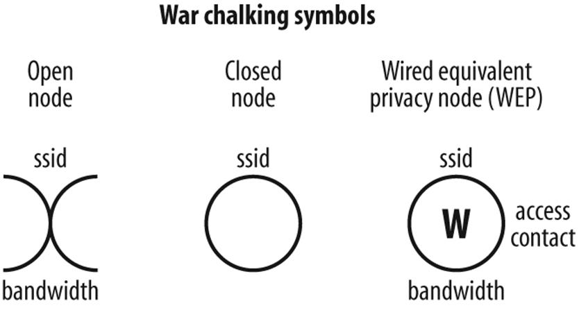
Figure 10-11. War chalking codes indicates the presence of Wi-Fi hot spots
Eavesdropping Defenses
The defense against eavesdropping is to stay off the air—not the goal of wireless communication. Clandestine operators adhere to strict schedules, transmitting only at prearranged times and powering down immediately after the message is sent. A wireless node that you would have to turn on each time you wished to use it would defeat the purpose of wireless, which is mobility and quick access. (It is always a good idea to turn off wireless access points when no one is using them, however, such as at night or on weekends in the case of most offices. There is no point in giving a determined attacker an unattended path into the network or in advertising the network’s location.) Besides, didn’t your parents tell you to turn off the lights when you left the room?
One potential downside to turning off your access point is that others who wish to install their own wireless systems over the weekend may determine the frequencies are unoccupied and set up shop. This sets up the potential for interference. Some administrators prefer to leave their access points on the air but remove as many identifying signals as possible. This allows them to show up in site surveys, but precludes attackers from gathering information that can be used against the network.
In addition to turning off the access point or suppressing ID, there are two main defenses against wireless eavesdropping attack:
§ Intrusion detection systems
§ Encryption systems
As they are somewhat more rare, let’s discuss the intrusion detection system (IDS) first. An intrusion detection system operates by monitoring something about a given computer (host-based IDS) or given network (network IDS). Logs are kept during monitoring; such logs can analyze attacks and provide documentation for possible legal action.
The IDS monitors the network for baseline changes, that is, any events that can signal an attack, such as someone unfamiliar logging on, or traffic of one kind or another spiking up or dipping suddenly. The IDS reports each such event, usually by paging a network administrator. The network admin can turn off the threatened access unit or isolate it from the network. The admin can also contact security forces, if they are available, and track down the eavesdropper.
The disadvantage of an IDS is that without an accurate baseline, it is hard for an IDS to detect anomalous traffic. Paging an admin in the middle of the night over a false alarm, or an attack that isn’t really happening, is called false positive. Too many false positives and the administrator is likely to disable the IDS, or change its settings and thresholds. These new settings may not pick up or relay a legitimate alarm; this situation is called a false negative. Obviously, neither false positives nor false negatives are desirable.
A full time method of protection that requires less fiddling uses encryption. Wi-Fi has several encryption options; unfortunately, an increasing number of them are falling to attacks by eavesdroppers.
Wired Equivalent Privacy (WEP) is the most common security protocol in older wireless networks. Its original algorithm is not very effective. Readily available software can monitor WEP transmissions until there is enough data to take advantage of a few loopholes, and thereafter will print out cleartext.
Wi-Fi Protected Access (WPA) —which is similar to Microsoft’s SSN—is less vulnerable to hacking. If you can choose between WEP and WPA, use WPA. Cisco users can take advantage of the LEAP protocol between other Cisco units.
AES and the Temporal Key Integrity Protocol (TKIP) can provide the most secure wireless networking. They will likely appear as the wireless standard IEEE802.11i.
HIPAA AND WIRELESS—PRESCRIPTION FOR TROUBLE?
I went to my doctor this summer for a checkup. When he was finished with his exam, he started clicking a stylus against a Compaq iPaq. I noticed a radio pack and an antenna on the back of his unit, so I asked “What are you doing about security for that thing?”
His answer was startling: “Security?”
This MD’s ignorance unfortunately represents the state of the knowledge of many healthcare practitioners today. Wireless is the new toy. But with wireless comes a responsibility for intense patient-record security, courtesy of the Health Insurance Portability and Accountability Act of 1996.
HIPAA created strong requirements for those who keep and transmit private patient records. The cavalier attitude my MD demonstrated can have big consequences, and the penalties for intentional violation are stiff. Clearly, decisions about the deployment of wireless technologies must take into account the implications of HIPAA security rules, which were issued in final form in February 2003.
Any electronic transmission of protected health information (PHI) comes under HIPAA auspices, and the watchwords are privacy and security. Practitioners must be sure that electronic communications are encrypted and that electronic devices are secure—that is, protected from loss, theft or unauthorized use.
Advanced Eavesdropping Attacks
Today, eavesdropping isn’t just eavesdropping. There are now advanced forms of it, and wireless may play a role in it. The easiest way to protect against encryption is to read messages before or after they are encrypted. Unfortunately, that is exactly how it is done, using techniques put forward by Dutch scientist Wim van Eck, who in 1985 demonstrated that he could pick up emissions from a VDU (video display unit) or computer screen, and reproduce them clearly several hundred meters away.
The fields that steer the beam that sweeps across your computer monitor or TV form a repetitive pattern, and like any other radio emission, they radiate and can be detected. If you monitor these fields using specialized equipment, it is possible to reinsert into the received signal the sync pulses that tell the beam when to start scanning the following line, or when to return to the top of the screen; this can be done by carefully tuning the correct oscillators. With skill, the display that you see on your screen is also visible to an operator sitting in the pizza van that has been mysteriously parked across the street for several hours. And since your screen is not likely to show encrypted data (after all, you have to be able to read it), the men in black get the cleartext just as you do.
There is a way to deal with this situation and it needs an acronym: Telecommunications Electronics Material Protected from Emanating Spurious Transmissions, or TEMPEST. TEMPEST is a set of standards that determine whether or not a device produces emanations that can be detected and decoded. Almost every device produces an electromagnetic signature that can be decoded, so when dealing with classified materials, TEMPEST certification becomes important. For more information, see Appendix B.
At the cutting edge of wireless weirdness is the idea that even if the field coming from a device is extremely small, to the point that the pizza truck guys cannot make it out, those same emanations may be able to exert an influence on a local source of emission, such as a radio transmitter. The transmitter signal may be detectable at a distance, hence the subtle influences from the signal you wish to eavesdrop may also be recoverable. There is a possibility that the electrostatic and electromagnetic vectors of a radio wave mentioned previously may contribute to this effect. Needless to say, a building with a floor full of wireless devices is a radio frequency cornucopia waiting to be sniffed by those who know what to look for.
Rogue Access Points
A much more down-to-earth threat for wireless networks is the same type of threat that faced networks back in the days of modems. Users would drag in a modem from home, hook it up unbeknownst to the network administrator, and proceed to create massive gashes in the security infrastructure.
In the same vein, rogue access points are extremely easy to install. Some are small enough to plug into a USB port. The defense against such installations is to monitor the environment, looking for unknown stations that attempt to attach to your network. Locating the stray can be a challenge but, generally speaking, a highly directional antenna can be used either with a laptop or with a handheld scanner designed especially for network maintenance (see Figure 10-12).
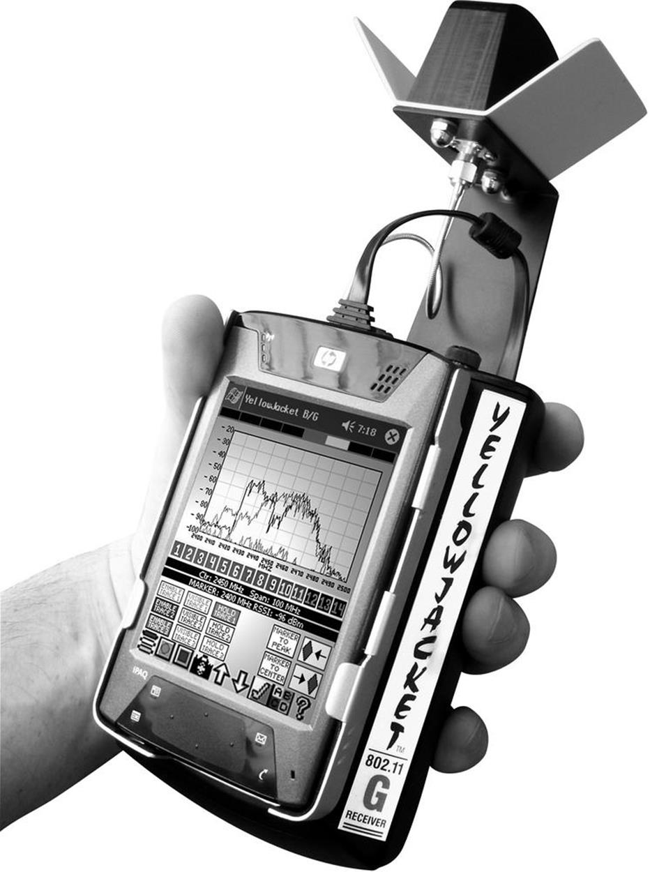
Figure 10-12. Wireless network maintenance tools, such as Yellowjacket, can guard against rogue access points
The culprit may well be you. As embarrassing as it sounds, it’s not unheard of for a network administrator to set up a wireless device in a conference room for a meeting, and then to forget about it.
80/20 RULES
Nothing makes a wireless network completely secure, but most networks can be tightened enough that attackers move to easier prey:
Cloak
Don’t broadcast service set identifiers (SSIDs). SSIDs, the 32-character identifiers in WLAN packet headers, can be easily sniffed, and can function as a sort of password. Turn them off. Legitimate users will still find the access point because they know its name. Always change the default user names and passwords that come in equipment from the factory. Hackers know these by heart.
Stealth
Don’t hand out a map of your network. Make it harder to navigate or to deduce the layout of the network by avoiding common names for network items exposed to the outside. Only trusted souls need to know what goes where.
Watch your channel plan
Most facilities use a three-channel plan to keep geographically overlapped access points from stepping on each other’s radiations. An attacker trying to set up a man-in-the-middle exploit will have to use off-channels. If you detect these, something is afoot.
A time of your choosing
If your office works 9-to-5, don’t run your wireless 24/7. Shut down during off hours. You can also control access via signal strength and speed. Signals decline with distance, so users who are in the parking lot instead of the lobby sound farther away. If users do not exceed a certain threshold for strength, cut them off. If a user is struggling to keep up, it may be because they are farther away. Don’t create a network security hole while trying to make up for a problematic network design or poor equipment.
Use serious security
Going without security is foolish. WEP is simply not adequate, because a fast network will give out enough packets for a crack in the time it takes to change a tire. Use WPA; use LEAP (look first); use TKIP or AES. Stay tuned for vulnerability notices.
Monitor, monitor
The most brilliant attackers will be able to get past your defenses, no matter what you do. Monitor for the attacks you cannot defend against. Your organization has a lobby ambassador to greet guests, and to call the cops if they act rowdy or threatening. Use an intrusion detection system to monitor against unruly wireless visitors who probe the network or attempt to access it at strange hours. Know what access points are where. Check to make sure that no new access points materialize, and no users inadvertently relay inside traffic outside.
Summary
Radio waves, being unbounded by cable or wiring, can reach many users who otherwise would be tied to a given desk or location. However, the fact that radio waves transmit information invisibly also allows them to leak information without detection. Anyone who can put a wireless device on the air can passively monitor, or actively invade, a wireless network. Further, wireless systems are prone to interference which can deny users intended services.
Proper antenna selection will do much to keep radio signals confined to the appropriate area. Careful attention to network cabling—all wireless networks end up connecting to a wired network at some point—will also help assure security for your wireless environment. Strictly discouraged are unauthorized or rogue access points. Installing such equipment without the knowledge, and approval of, network administrators can create a tremendous security hazard, even if the installer has only the best of intentions.