AutoCAD Platform Customization: User Interface and Beyond (2014)
Chapter 9. Defining Shapes, Linetypes, and Hatch Patterns
The Autodesk® AutoCAD® program uses shapes, linetypes, and hatch patterns to control the
way text, linework, and fi lled areas look. Shapes are the foundation for the letters of an SHX font fi le, but they can also be inserted into a drawing or used to help communicate design information with complex linetypes.
All objects in a drawing are affected by linetypes because they control how the line work of an object appears. You can create your own custom linetypes with dash, dot, and gap combinations different from those that come with AutoCAD and even include a text string or shape. You can also create custom hatch patterns to introduce new linework to fi ll a closed area.
Creating and Compiling Shapes
Shapes are objects that can represent straight and curved linework in a single object. Over the years, shapes have held several different roles in designs created with AutoCAD. Shapes were the original concept that eventually evolved into blocks, and they are still are used today to defi ne the letters in an SHX font fi le and to display objects in a complex linetype.
Shapes are stored in fi les with the .shp extension. SHP fi les are in the ASCII text format and can be edited with Notepad (Windows) or TextEdit (Mac OS). A SHP fi le can contain multiple shapes. Each shape defi nition in a SHP fi le must have a unique name, and in the case of creating a font fi le, the names must follow a specifi c numbering convention as well. After you create a SHP fi le, it must be compiled into an SHX fi le (using the compile command) before any of the shapes in the fi le can be used with AutoCAD.
TIP On Windows, you can use the Express Tools Make Shape tool to defi ne a shape without needing to know the syntax. Click Express tab ➢ Tools panel ➢ panel’s title bar ➢ Make Shape.
Structure of a Shape
Each shape is composed of two lines: header and specifi cation. The header (or fi rst) line contains three components: the shape number, the number of bytes in the shape specifi cation, and a name. The syntax of the header line for a shape is as follows:
*shape_number,definition_bytes,shape_name
Here is an example of a header line for a shape that has the number 136, contains 6 bytes, and is named DMOND:
*136,6,DMOND
When creating the header line for a shape, keep the following in mind:
◆ The line must begin with an asterisk.
◆ The line length cannot exceed 128 characters.
Table 9.1 provides more information about each of the components that make up the header
line of a shape.
Table 9.1:
Components of a shape header line
Code
Description
shape_number
Unique number for a shape within the fi le. All shapes must have an assigned number
between 1 and 258, but the number can be increased up to 32,768 for Unicode fonts.
When you are defi ning a font, keep in mind that the numbers 256 (U+00B0), 257
(U+00B1), and 258 (U+2205) are reserved for the degree sign, plus or minus sign, or
diameter symbol, respectively.
definition_
Total sum of bytes used in the shape specifi cation line. Specifi cation groupings
byte
contained in parentheses are not counted as a single byte, but each item in the group-
ing is counted as a single byte.
shape_name
Name used to identify the shape for insertion into a drawing or use as part of a complex
linetype. The name must be specifi ed in all uppercase letters.
The second and subsequent lines of the shape specifi cation consist of a comma-delimited
list of code values that defi ne the objects that make up the appearance of the shape. Each shape specifi cation must end with 0 (zero). The syntax of the specifi cation line looks like this: spec1,spec2,specN,...,0
Here is an example of a shape specifi cation that draws four line segments at four different angles to form a diamond:
1,023,02D,02B,025,0
Table 9.2 explains the codes that can make up a specifi cation line of a shape. Figure 9.1
shows the available vector or octant angles that can be used when drawing straight vectors or octant arcs.
Table 9.2:
Shape specifi cation line codes
Code
Description
000 or 0
Represents the end-of-shape defi nition marker. All shape defi nitions must end with this code; otherwise an error is generated when the shape fi le is compiled. The error message
displayed is Premature end of file.
Syntax: 0
001 or 1
Controls the Pen Down drawing mode. Used to draw straight vectors.
Syntax: 1,0LA
L: Vector length. Valid range is 0 to 15 units. For values 10 to 15, use hex representation (letters A to F).
A: Vector angle. Valid range is 0 to 15, where each number represents an increment of about 22.5 degrees. For values 10 to 15, use hex representation (letters A to F).
002 or 2
Controls the Pen Up drawing mode. Used to move the pen to a new location without drawing a vector.
Syntax: 2,0LA
L: Vector length. Valid range is 0 to 15 units. For values 10 to 15, use hex representation (letters A to F).
A: Vector angle. Valid range is 0 to 15; each number represents an increment of about 22.5
degrees. For values 10 to 15, use hex representation (letters A to F).
003 or 3
Scales down by a specifi ed factor any vectors that follow.
Syntax: 3, Div
Div: Divisor or scale reduction factor. Valid range is 0 to 15 units. For values 10
to 15, use hex representation (letters A to F).
004 or 4
Scales up by a specifi ed factor any vectors that follow.
Syntax: 4, Mul
Mul: Multiplier or scale factor. Valid range is 0 to 15 units. For values 10 to 15, use hex representation (letters A to F).
005 or 5
Saves, or pushes, the current position in the shape. Doing so allows you to return to the position and continue drawing. A maximum of four locations can be saved at any one time.
If the maximum number of saves is exceeded, the error message Position stack over-
flow in shape <number> is displayed.
Syntax: 5
Table 9.2:
Shape specification line codes (continued)
Code
Description
006 or 6
Restores, or pops, the most recently saved position. A maximum of four positions can be
restored. Th
e positions are returned from most recent to earliest saved. If you attempt to
restore more positions than those stored, the error message Position stack underflow
in shape <number> is displayed. Autodesk recommends that you restore all saved positions before you add the end-of-shape defi nition marker. Not restoring all saved positions could aff ect other shapes.
Syntax: 6
007 or 7
References another shape defi ned in the same shape fi le. By referencing other shapes, it allows you to defi ne new shapes without having to duplicate or create long shape
defi nitions.
Syntax: 7, Num
Num: Number of the shape to use in the current file.
008 or 8
Draws a vector to a given coordinate value, thereby giving you much greater control over the vectors that can be drawn when compared to what can be done using the codes 0 ( Pen Down) and 1 ( Pen Up). Coordinate value range is –128 to 127 along the X- or Y-axis. Optionally, you can put the coordinates in parentheses to make a shape defi nition easier to read.
Syntax: 8, X, Y or 8,( X, Y)
X: Displacement along the X-axis.
Y: Displacement along the Y-axis.
009 or 9
Draws multiple vectors based on coordinate pairs. Coordinate value range is –128 to 127
along the X- or Y-axis. Optionally, you can put the coordinates in parentheses to make a
shape
defi nition easier to read.
Syntax: 9, X , Y , X , Y , X , Y or 9,( X , Y ),( X , Y ),( X , Y ) 1
1
2
2
n
n
1
1
2
2
n
n
Xn: Displacement along the X-axis.
Yn: Displacement along the Y-axis.
00A or 10
Draws an arc; more specifi cally, it draws an octant arc because the arc can span one or more 45-degree octants. The arc must start and end at one of the octants. Each octant is numbered counterclockwise from 0 to 7. Figure 9.1 shows each octant value and the equivalent angle in degrees.
Syntax: 10, Rad,0SE
Rad: Radius of the arc expressed in radians. Valid range is 1 to 255.
S: Start octant for the arc.
E: End octant for the arc.
Table 9.2:
Shape specification line codes (continued)
Code
Description
00B or 11
Draws an arc that doesn’t follow the octant boundaries like those drawn with code 10. This
type of arc is known as a fractional arc. Although using code 11 provides greater fl exibility when creating an arc, it requires additional planning and calculating to get the expected results.
The start of the arc is calculated by taking the diff erence in degrees between the starting octant and the start of the arc. After the diff erence is calculated, you multiply the number by 256 and then divide the new value by 45. This gives you the start off set value.
The end of the arc is calculated by taking the diff erence between the last octant boundary crossed and the end of the arc. After the diff erence is calculated, you multiply the number by 256 and then divide the new value by 45. This gives you the end off set value.
Syntax: 11, SO, EO, HRad, Rad, 0SE
SO: Start offset from octant for the arc (0 when start offset is on an octant).
EO: End offset from octant for the arc (0 when end offset is on an octant).
HRad: High radius for the arc, the value is 0 (zero) if Rad is less than
255. To generate an arc greater than 255, multiply the HRad value by 256 and add it to Rad.
Rad: Radius of the arc expressed in radians. Valid range is 1 to 255 when
HRad is set to 0 (zero).
S: Start octant for the arc.
E: End octant for the arc.
00C or 12
Draws an arc based on a displacement on the XY plane and a bulge value. This type of arc is
known as a bulge fractional arc. Coordinate value range is –127 to 127 along the X- or Y-axis, and the bulge value range is –127 to 127.
Syntax: 12, X, Y, B
X: Displacement along the X-axis.
Y: Displacement along the Y-axis.
B: Bulge of the arc. The bulge is calculated using the formula ((2 × H/ D)
× 127), where H is the height of the bulge (measured from the midpoint of
the arc’s chord to the arc’s circumference). D is the length of the
arc’s chord, which is the distance between the start and endpoint of
the arc.
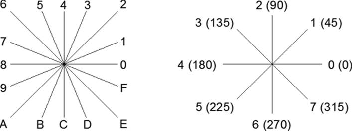
Table 9.2:
Shape specification line codes (continued)
Code
Description
00D or 13
Draws multiple arcs based on coordinate pairs and bulge values, which are the same as code 00C. Coordinate value range is –127 to 127 along the X- or Y-axis, and the bulge value range is –127 to 127. Optionally, you can put the values in parentheses to make the shape defi nition easier to read. You must add 0,0 after the last bulge.
Syntax: 13, X , Y , B , X , Y , B , X , Y , B ,0,0 or 13,( X , Y , B ),( X , Y , B ),( X , 1
1
1
2
2
2
n
n
n
1
1
1
2
2
2
n
Y , B ),(0,0)
n
n
X: Displacement along the X-axis.
Y: Displacement along the Y-axis.
B: Bulge of the arc. The bulge is calculated using the formula ((2 × H/D)
× 127). H is the height of the bulge, which is measured from the midpoint
of the arc’s chord to the arc’s circumference. D is the length of the
arc’s chord, which is the distance between the start and endpoint of
the arc.
00E or 14
Defi nes that the shape can be used with a vertical orientation when defi ning a font. When creating text with a vertical orientation, the specifi cations following the code are used.
Commonly, this code is used to relocate the start and endpoints of the letter. I discuss creating a font later in this chapter in the “Defi ning a Font” section.
Syntax: 14
Figure 9.1
Determining which
value to use for vec-
tor angles (left)
or octants (right)
NOTE Th e shape_samples.shp fi le that is part of the sample fi les for this book contains a variety of shape defi nitions that demonstrate the use of the diff erent codes. The sample fi les
can be downloaded from www.sybex.com/go/autocadcustomization.
Now that you have an understanding of the syntax for a shape defi nition, here is what the defi nition of the standard BAT shape looks like from the ltypeshp.shx fi le. The BAT shape is used with the Batting linetype (see Figure 9.2) defi ned in the acad.lin and acadiso.lin fi les.
*134,6,BAT
025,10,2,-044,02B,0
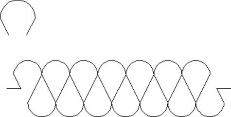
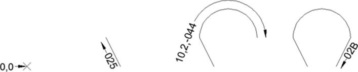
Figure 9.2
BAT shape inserted
into the drawing
(top) along with a
polyline with the
Batting linetype
assigned (bottom)
NOTE Th e ltypeshp.shx fi le is a compiled fi le and can’t be viewed using Notepad (Windows) or TextEdit (Mac OS). However, Autodesk does provide the original source for this fi le. Th e
ltypeshp.shp fi le in the Support folder within the AutoCAD installation folder contains the source for the shapes in the ltypeshp.shx fi le.
Table 9.3 explains each code and value of the BAT shape defi nition.
Table 9.3:
Codes and values for a BAT shape
Value
Description
* Indicates the start of the shape
134,
Number assigned to the shape
6,
Length of the shape defi nition in bytes
BAT
Name of the shape
025,
Draw a vector from the current location approximately 2 units in the 5 direction
(112.5 degrees)
10,
Indicates the start of an octant arc
2,
Th
e radius of the octant arc
-044,
Start the arc in octant 4 (180 degrees) and go clockwise 4 octants (0 degrees)
02B,
Draw a vector from the current location approximately 2 units in the B direction
(247.5 degrees)
0
End marker for the shape
Figure 9.3 shows a visual breakdown of how each part of the shape looks as AutoCAD inter-
prets the BAT shape defi nition.
Figure 9.3
Breakdown of the
BAT shape
Def ining a Shape
Shape defi nitions are created and stored in SHP fi les using an ASCII text editor, such as Notepad (Windows) and TextEdit (Mac OS). While you could add your shape defi nitions to the ltypeshp.shp fi le and then recompile that fi le, I recommend storing your custom shape defi nitions in your own SHP fi les.
The following explains how to create a new SHP fi le named myshapes.shp on Windows:
1. Do one of the following:
◆ Click Start button ➢ [All] Programs ➢ Accessories ➢ Notepad (Windows XP and Windows 7).
◆ On the Start screen, type note and click Notepad (Windows 8).
2. In Notepad, click File ➢ Save As.
3. In the Save As dialog box, browse to the MyCustomFiles folder you created for the book in the Documents (or My Documents) folder, or to the location in which you want to create the SHP fi le.
4. In the File Name text box, type myshapes.shp.
5. From the Save As Type drop-down list, select All Files (*.*).
6. From the Encoding drop-down list, select ANSI. Click Save.
7. In the editor area, type the following:
*136,6,DMOND
1,023,02D,02B,025,0
8. Press Enter after the last line in the shape defi nition.
9. Click File ➢ Save.
If you are using AutoCAD on Mac OS, you can use these steps to create a new SHP fi le
named myshapes.shp:
1. In the Mac OS Finder, click Go ➢ Applications.
2. In the Finder window, double-click TextEdit.
3. On the Mac OS menu bar, click TextEdit ➢ Preferences.
4. In the Preferences dialog box, click the New Document tab.
5. In the Format section, click Plain Text.
6. Close the Preferences dialog box.
7. Click File ➢ Save.
8. In the Save dialog box, type myshapes.shp in the Save As text box.
9. Browse to the MyCustomFiles folder you created for the book in the Documents folder, or to the location in which you want to create the SHP fi le.
10. From the Plain Text Formatting drop-down list, select Unicode (UTF-8).
11. Enable the If No Extension Is Provided, Use *.TXT check box, and then click Save.
12. In the editor area, type the following:
*136,6,DMOND
1,023,02D,02B,025,0
13. Press Enter after the last line in the shape defi nition.
14. Click File ➢ Save.
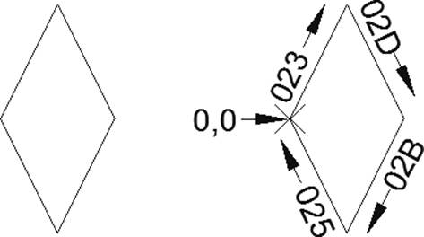
Figure 9.4 shows what the DMOND shape looks like when used in a drawing and also how
the shape defi nition works.
Figure 9.4
Inserted DMOND
shape (left) and a
breakdown of its
shape defi nition
(right)
Compiling a Shape
Before you can use a shape defi nition in a SHP fi le in AutoCAD, you must compile the fi le using the compile command. Compiling a SHP fi le validates the shape defi nitions in the fi le, and if there are no errors, the process generates an SHX fi le. The following explains how to compile the myshapes.shp fi le that I explained how to create in the “Defi ning a Shape” section.
NOTE You can also fi nd the myshapes.shp fi le as part of the sample fi les for this book. Th e sample fi les can be downloaded from www.sybex.com/go/autocadcustomization.
1. At the Command prompt, type compile and press Enter.
2. In the Select Shape Or Font File dialog box, browse to the MyCustomFiles folder that you created for this book in the Documents (or My Documents) folder, or browse to the folder
that contains the myshapes.shp fi le that you created if you placed it elsewhere.
3. Click Open. The following message is displayed if the command succeeds in compiling the fi le:
Compiling shape/font description file Compilation successful. Output file
myshapes.shx contains 49 bytes.
If an error message is displayed, go back to the SHP fi le and fi x the shape defi nition.
Loading and Inserting a Shape
After a SHP fi le has been compiled as an SHX fi le, you can load the shapes into a drawing so they can be inserted using the shape command, or you can use the shape in a complex linetype.
I cover creating complex linetypes later in this chapter in the “Creating and Using Custom Linetypes” section.
Before you proceed, make sure you have created and compiled the myshapes.shp fi le. The
creation and compiling of the SHP fi le was discussed in the “Defi ning a Shape” and “Compiling a Shape” sections earlier in this chapter.
NOTE You can also fi nd the myshapes.shx fi le as part of the sample fi les for this book. Th e sample fi les can be downloaded from www.sybex.com/go/autocadcustomization.
The following explains how to load the compiled shape (SHX) fi le named myshapes.shx into a drawing:
1. At the Command prompt, type load and press Enter.
2. In the Select Shape File dialog box, browse to the MyCustomFiles folder that you created for this book in the Documents (or My Documents) folder, or browse to the folder that
contains the myshapes.shx fi le if you placed it elsewhere.
3. Click Open.
You can use the following steps to insert the shape named DMOND that was made available
after loading the myshapes.shx fi le into the drawing fi le:
1. At the Command prompt, type shape and press Enter.
2. At the Enter shape name or [?]: prompt, type dmond and press Enter.
3. At the Specify insertion point: prompt, specify a coordinate point in the drawing.
4. At the Specify height <1.0000>: prompt, specify a numeric value and press Enter.
5. At the Specify rotation angle <0>: prompt, specify a numeric value and press Enter.
NOTE If you change the defi nition of a shape, you must remove all instances that use the shape defi nition from any drawing that you want to use the new shape defi nition in, and then remove the shape defi nition from those drawings with the purge command. After the shape
defi nition has been removed, you can load the updated shape defi nition and then reinsert each of the shape objects.
Def ining a Font
Using shapes, you can defi ne your own letters to create a custom font. Much of what you need to know has already been explained earlier in this chapter. However, there are a few conventions that you need to follow when specifying a number or name for a shape that is used to defi ne a font. Here are the requirements that you must follow when defi ning a shape font fi le:
◆ The value of the shape_number variable must correspond to the ASCII code value of the
character it represents. To know what ASCII code value represents a specifi c character, you can use the AutoLISP® function ascii. For example, (ascii "a") returns an ASCII code value of 97, whereas (ascii "A") returns an ASCII code value of 65. As you can see from the examples, uppercase and lowercase letters return different values.
◆ The shape_name is commonly used to communicate whether the shape represents an
uppercase or lowercase letter. However, unlike the shape numbers in a shape font fi le, the name doesn’t hold any meaningful signifi cance. The sample font fi les that are included
in the AutoCAD Help system do follow a specifi c naming convention for uppercase and
lowercase letters, though. For example, the sample fi le uses uca for the shape name of the uppercase letter A and lca for the lowercase a shape defi nition.
◆ A custom shape font fi le must defi ne a line-feed shape, which is represented by the ASCII code value 10. The line feed does not draw a character but acts as a carriage return and
drops down one line.
◆ Pen Up movements must be used to set the start and endpoint of a letter and to defi ne the spacing between letters.
◆ Each shape font fi le must include a special header that defi nes the spacing above and below the baseline of uppercase and lowercase letters. The header must use the following syntax:
*UNIFONT,4,font_name
above,below,modes,0
For more information on creating a shape font fi le, see the AutoCAD Help system.
TIP AutoCAD includes two sample shape fonts that you can experiment with. Th e samples are included in the AutoCAD Help system and can be found by searching on the keywords “font
sample.” Copy the sample shape defi nitions to a SHP fi le and then compile the fi le so you can use it in AutoCAD.
Creating and Using Custom Linetypes
Linetypes are used to communicate the intent of the linework that makes up a design. Most of the linetypes that come with AutoCAD are universal to all types of designs, not just architectural or mechanical. But there are times when you want to create your own linetypes. You might want to create a new linetype in these situations:
◆ When a standard linetype doesn’t display well in your drawings using the global linetype scale factor that other linetypes do. In this case, you might simply be creating a new linetype based on an existing linetype, but it might have longer dashes or wider gaps.
◆ When a standard linetype doesn’t fi t your needs. For example, while working on civil-
engineering drawings, you might want to introduce new linetypes that help to
communicate the location of a utility line or roadway offset.
AutoCAD supports two kinds of linetype:
◆ Simple linetypes are made up of gaps, dashes, and/or dots.
◆ Complex linetypes are made up of gaps, dashes, and/or dots, plus a text string or shape.
Linetypes are stored in fi les with the .lin extension. LIN fi les are in the ASCII text format and can be edited with Notepad (Windows) or TextEdit (Mac OS). The linetypes that AutoCAD
comes with are stored in the acad.lin and acadiso.lin fi les. New linetypes can be added
to these two fi les, or you can add them to a LIN fi le that contains the linetypes that have been approved for use as part of your company’s standards.
I recommend storing the linetypes you create in a LIN fi le separate from those that come with AutoCAD. This makes it easier to back up your custom fi les and migrate to a future release.
However, if you want to add your linetypes to one of the standard LIN fi les that come with 230 | CHAPTER 9 DEFINING SHAPES, LINETYPES, AND HATCH PATTERNS
AutoCAD, place them after the User Defined Linetypes section near the bottom of the fi le.
This section is denoted by the following text:
;; User Defined Linetypes
;;
;; Add any linetypes that you define to this section of
;; the file to ensure that they migrate properly when
;; upgrading to a future AutoCAD version. If duplicate
;; linetype definitions are found in this file, items
;; in the User Defined Linetypes section take precedence
;; over definitions that appear earlier in the file.
;;
TIP On Windows, you can use the Express Tools Make Linetype tool to create a linetype without needing to know the syntax. Click Express tab ➢ Tools panel ➢ panel’s title bar ➢ Make Linetype.
Structure of a Linetype
Each linetype defi nition is made up of two lines. The fi rst line defi nes the name and an optional description for the linetype:
*linetype_name[, description]
Here is an example of a linetype defi nition with the name DASH_DOT_DASH and a
description:
*DASH_DOT_DASH, DDD __ . __ . __ . __ . __ . __ . __ . __
When naming or describing a linetype, keep the following in mind:
◆ The name must be preceded by an asterisk. This indicates the start of a new linetype
defi nition.
◆ The name should be short and indicate the intended use. I recommend limiting a linetype name to 45 characters, as long names are harder to view in the AutoCAD user interface.
◆ Descriptions are optional, but I recommend adding them to your linetypes. If you do add a description, make sure to add a comma after the name of the linetype.
◆ The fi rst line of a linetype defi nition is limited to 280 characters. This means that the linetype name, comma, and description combined must be 279 or fewer characters in total,
because the asterisk counts as one character.
The second line of a linetype defi nition contains the actual values that describe how the pattern of the linetype should look:
A,val1,val2,valN,...
Here is an example of a linetype pattern that contains a dash, a gap, a dot, and a second gap: A,.75,-.25,0,-.25
Each linetype pattern must start with an A, which indicates that pattern alignment is being used. Pattern alignment ensures that dashes are used as the endpoints of a linetype object instead of a gap or dot. After the pattern alignment indicator, a linetype pattern can include one or more numeric values that need to be separated by a comma.
The following describes the possible numeric values that can be used to defi ne the pattern of a simple linetype:
◆ A positive number represents a dash (or line) segment.
◆ A zero represents a dot.
◆ A negative number represents a gap (or space).
Now that you understand the basics of a linetype defi nition, here is the defi nition of the standard Center linetype from the acad.lin fi le:
*CENTER,Center ____ _ ____ _ ____ _ ____ _ ____ _ ____
A,1.25,-.25,.25,-.25
Table 9.4 explains each of the values used to defi ne the Center linetype.
Table 9.4:
Values of the Center linetype
Value
Description
* Indicates the start of the linetype
CENTER
Linetype name, a comma separator, and the linetype description
, Center ____ _ ____ _
Linetype description
____ _ ____ _ ____ _ ____
A,
Pattern alignment fl ag
1.25,
Dash of 1.25 units when the LTSCALE system variable is set to 1
-.25,
Gap of 0.25 units
.25,
Dash of 0.25 units
-.25
Gap of 0.25 units
In addition to dashes, dots, and gaps, a linetype pattern can include a value that defi nes a text string or shape object. A text string or shape object value in a linetype pattern is designated
by a grouping of values within a set of square brackets. The syntax for a linetype pattern that includes a text string or shape object value is as follows:
["text_string",style_name,scale,rotation,x-offset,y-offset]
[shape_name,shape_filename,scale,rotation,x-offset,y-offset]
Table 9.5 explains each of the values used to add a text string and shape object to a linetype pattern.
Table 9.5:
Text string and shape object values
Value
Description
"text_string"
Text to place in the linetype pattern.
style_name
Text style name to use for the text. The style name must exist in the drawing fi le for it
to be used.
shape_name
Name of the shape to place in the linetype pattern.
shape_
Filename of the compiled shape (SHX) fi le that contains the shape being placed in the
filename
linetype. This fi le must be located in the AutoCAD support fi le search paths.
scale
Scale factor to be applied to the text or shape.
Syntax: S=#.#
rotation
Rotation type and angle to be applied to the text or shape.
You can choose from three rotation types:
Upright (U)—Rotates the text or shape so it is displayed upright or near upright, and
not upside down or backward.
Relative (R)—Rotates the text or shape relative to the angle of the objects to which
the linetype is applied.
Absolute (A)—Rotates the text or shape so it always has the same orientation based
on the world coordinate system, no matter the angle of the object to which the line-
type is applied.
Syntax: U=#.#, R=#.#, or A=#.#
x-offset
Shifts the text or shape along the X-axis on the linetype; a positive number moves the
text or shape to the endpoint of the object to which the linetype is applied, whereas a
negative number moves the text or shape to the start point.
Syntax: X=#.#
y-offset
Shifts the text or shape along the Y-axis on the linetype; moves the text or shape up or
down based on the direction of the object to which the linetype is applied. A positive
value moves the text or shape up when an object is drawn left to right.
Syntax: Y=#.#
Here are two of the standard linetype defi nitions from the acad.lin fi le. The fi rst contains a text string and the second contains a shape object.
*HOT_WATER_SUPPLY,Hot water supply ---- HW ---- HW ---- HW ----
A,.5,-.2,["HW",STANDARD,S=.1,U=0.0,X=-0.1,Y=-.05],-.2
*FENCELINE2,Fenceline square ----[]-----[]----[]-----[]----[]---
A,.25,-.1,[BOX,ltypeshp.shx,x=-.1,s=.1],-.1,1
Defi ning a Custom Linetype
Linetype defi nitions are created and stored in LIN fi les using an ASCII text editor, such as Notepad (Windows) and TextEdit (Mac OS). As I previously mentioned, I recommend storing
your custom linetypes in a LIN fi le that you create and not one that came with AutoCAD.
The following explains how to create a new LIN fi le named mylinetypes.lin on Windows:
1. Do one of the following:
◆ Click Start button ➢ [All] Programs ➢ Accessories ➢ Notepad (Windows XP and Windows 7).
◆ On the Start screen, type note and click Notepad (Windows 8).
2. In Notepad, click File ➢ Save As.
3. In the Save As dialog box, browse to the MyCustomFiles folder you created for the book in the Documents (or My Documents) folder, or to the location in which you want to create the LIN fi le.
4. In the File Name text box, type mylinetypes.lin.
5. From the Save As Type drop-down list, select All Files (*.*).
6. From the Encoding drop-down list, select ANSI. Click Save.
If you are using AutoCAD on Mac OS, you can use these steps to create a new LIN fi le named mylinetypes.lin:
1. In the Mac OS Finder, click Go ➢ Applications.
2. In the Finder window, double-click TextEdit.
3. On the Mac OS menu bar, click TextEdit ➢ Preferences.
4. In the Preferences dialog box, click the New Document tab.
5. In the Format section, click Plain Text.
6. Close the Preferences dialog box.
7. Click File ➢ Save.
8. In the Save dialog box, type mylinetypes.lin in the Save As text box.
9. Browse to the MyCustomFiles folder you created for the book in the Documents folder, or to the location in which you want to create the LIN fi le.
![]()
10. From the Plain Text Formatting drop-down list, select Unicode (UTF-8).
11. Enable t he If No Extension Is Provided, Use *.TXT check box, and then click Save.
Simple Linetype
A simple linetype named DASH_DOT_DASH can be added to a LIN fi le by doing the following: 1. Start Notepad (Windows) or TextEdit (Mac OS), if the application is not already open.
2. Click File ➢ Open.
3. In the Open dialog box, browse to and select the mylinetypes.lin fi le that you created earlier in this section or the LIN fi le you want to edit. Click Open. On Windows, you will need to select All Files (*.*) from the Files Of Type drop-down list to see the LIN fi le.
4. In the editor window, type the following:
;; My Simple Linetypes
*DASH_DOT_DASH, DDD __ . __ . __ . __ . __ . __ . __ . __
A,.75,-.25,0,-.25
5. Click Save.
Figure 9.5 shows what the Dash Dot Dash linetype looks like when used in a drawing.
Figure 9.5
Dash Dot Dash line-
type assigned to a
polyline
Complex Linetype
The next example defi nes a complex linetype named PLOT_LINE that displays the text string PL: 1. Start Notepad (Windows) or TextEdit (Mac OS), if the application is not already open.
2. Click File ➢ Open.
3. In the Open dialog box, browse to and select the mylinetypes.lin fi le that you created earlier in this section or any other LIN fi le you want to edit. Click Open. On Windows,
you will need to select All Files (*.*) from the Files Of Type drop-down list to see LIN fi les.
4. In the editor window, type the following:
;; My Complex Linetypes
*PLOT_LINE,Plot line ----PL----PL----PL----PL----PL----PL----
A,.25,-.125,["PL",STANDARD,S=.1,U=0.0,X=-0.1,Y=-.05],-.1
5. Click Save.
![]()
Figure 9.6 shows what the Plot Line linetype will look like when used in a drawing.
Figure 9.6
Plot Line linetype
assigned to a
polyline
Loading a Custom Linetype
Linetypes are loaded into a drawing using the Linetype Manager, which is displayed with
the linetype command. The following explains how to load and use the custom linetypes
Dash Dot Dash and Plot Line that you added to a LIN fi le in the “Defi ning a Custom Linetype”
section. I explain how to adjust the scale factors that affect the display of linetypes in the
“Controlling the Display of Linetypes” section.
NOTE You can fi nd the custom linetypes in the fi le mylinetypes.lin that is part of the sample fi les for this book. The sample fi les can be downloaded from www.sybex.com/go/
autocadcustomization.
For AutoCAD on Windows, use these steps:
1. On the ribbon, click Home tab ➢ Properties panel ➢ Linetypes drop-down list ➢ Other (or at the Command prompt, type linetype and press Enter).
2. When the Linetype Manager opens, click Load.
3. When the Load Or Reload Linetypes dialog box opens, click File.
4. In the Select Linetype File dialog box, browse to and select the mylinetypes.lin fi le that you created earlier in this section or the LIN fi le in which you added the custom
linetypes. Click Open.
5. In the Available Linetypes list, press and hold the Ctrl key and then select the DASH_
DOT_DASH and PLOT_LINE linetypes. Click OK.
6. In the Linetype Manager, select DASH_DOT_DASH and click Current.
7. Click OK to return to the drawing window.
8. Start the pline command and draw a new polyline with multiple segments.
9. On the ribbon, click Home tab ➢ Properties panel ➢ Linetypes drop-down list ➢
PLOT_LINE.
10. Start the pline command again and draw a new polyline with multiple segments.
11. At the Command prompt, type ltscale and press Enter.
12. At the Enter new linetype scale factor <1.0000>: prompt, type 6 and press Enter.
You might need to adjust the global linetype scale factor or the length of the polyline segments to see the dashes, gaps, dots, and text displayed as part of the linetypes.
For AutoCAD on Mac OS, use these steps:
1. On the menu bar, click Format ➢ Linetype (or at the Command prompt, type linetype and press Enter).
2. When the Linetype Manager opens, click the + (plus sign).
3. When the Load Or Reload Linetypes dialog box opens, click the Files button located to the right of the Files drop-down list.
4. In the Select Linetype File dialog box, browse to and select the mylinetypes.lin fi le that you created earlier in this section or the LIN fi le in which you added the custom linetypes. Click Open.
5. In the Available Linetypes list, hold down the Command key and select the DASH_DOT_DASH and PLOT_LINE linetypes. Click Add.
6. In the Linetype Manager, double-click the DASH_DOT_DASH linetype.
7. Click Save to return to the drawing window.
8. Start the pline command and draw a new polyline with multiple segments.
9. On the Properties palette, click the Linetype drop-down list and select PLOT_LINE.
10. Start the pline command and draw a new polyline with multiple segments.
11. At the Command prompt, type ltscale and press Enter.
12. At the Enter new linetype scale factor <1.0000>: prompt, type 6 and press Enter.
You might need to adjust the global linetype scale factor or the length of the polyline segments to see the dashes, gaps, dots, and text displayed as part of the linetypes.
TIP You can use the load option of the -linetype command on both Windows and Mac OS to load a custom linetype with a script, command macro, or AutoLISP program.
Controlling the Display of Linetypes
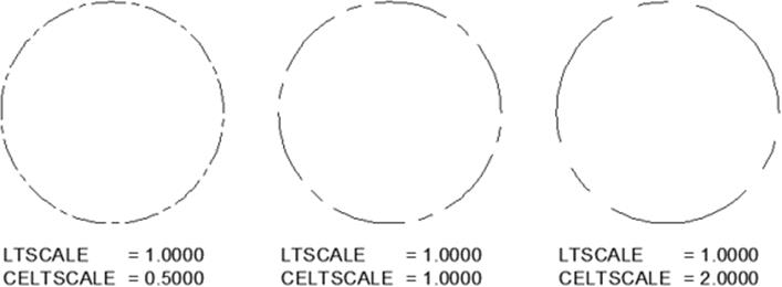
Four system variables control the scale factor that is used to adjust the size at which the dashes, gaps, text, and shapes that make up a linetype pattern appear. These system variables are as follows:
CELTSCALE Linetype scale factor that is applied to each new object created.
LTSCALE Linetype scale factor that is applied to all objects in a drawing.
MSLTSCALE Enables the scaling of the linetypes assigned to objects on the Model tab based on the current annotation scale. Use a value of 0 (zero) to disable the scaling of linetypes based on the current annotation scale; a value of 1 enables the scaling of linetypes.
Default value is 1.
PSLTSCALE Enables the scaling of linetypes of objects displayed in the paper space viewports on a named layout. Use a value of 0 (zero) to scale the linetype for objects based on the
drawing units of the space they are drawn in and scaled by the global linetype scale factor stored in the ltscale system variable. Using a value of 1 scales all linetypes in model space or paper space equally based on the current scale factor stored in the ltscale system variable, no matter the current scale of each viewport.
Based on the values of the system variables I previously mentioned, AutoCAD calculates the linetype scale factor for each individual object in a drawing. The primary method used to calculate the scale factor that is applied to a linetype is to multiply an object’s assigned linetype scale factor by the global linetype scale factor stored in the ltscale system variable.
For example, if an object is assigned a linetype scale factor of 0.75 and the ltscale system variable is set to 48, the fi nal scale factor used to control the display of the linetype pattern applied to the object would be 36. If the object’s individual linetype scale factor were 2 and ltscale were still 48, the fi nal scale factor used to control the display of the linetype pattern applied to the object would be 96. You can see the results of assigning the individual linetype scale factors in Figure 9.7.
Figure 9.7
Same object with
diff erent linetype
scale factors
Normally, most objects are assigned an individual linetype scale factor of 1. In situations where an object might be too small for the current global linetype scale, I recommend changing that object’s linetype scale factor so the gaps, text, and shapes of the assigned linetype can be seen well. If you don’t, the linetype pattern can appear as a single continuous dash.
Creating and Applying Custom Hatch Patterns
Hatch patterns allow you to fi ll closed areas with a repeating set of linework; they are commonly used on elevation and section views to help communicate the types of materials
used. The hatch patterns that ship with AutoCAD represent a variety of materials that can be used in architectural, civil, or mechanical drawings.
However, the selection of hatch patterns that are included with AutoCAD are somewhat lim-
ited compared to all the materials that can be found on a building or manufactured product in the real world. For those materials that don’t have a hatch pattern, you could create your own.
Similar to linetype patterns, hatch patterns are defi ned with a series of dashes, gaps, and dots.
Hatch patterns do support a few additional characteristics that allow you to control the offsets and angles of the linework that make up the hatch pattern.
Hatch patterns are stored in fi les with the .pat extension. PAT fi les are in the ASCII text format and can be edited with Notepad (Windows) or TextEdit (Mac OS). The hatch patterns that ship with AutoCAD are stored in the acad.pat and acadiso.pat fi les. New hatch patterns can be added to these fi les, or you can create your own PAT fi les. If you create your own PAT fi les, each hatch pattern must be in its own fi le and the name of the PAT fi le must be the same as the hatch-pattern name. For example, if you create a hatch pattern named pavement, the PAT fi lename must be pavement.pat.
I recommend storing the hatch patterns that you create in their own PAT fi les to keep them separate from those that come with AutoCAD. This makes it easier to back up your custom
fi les and migrate to future releases. However, if you want to add your hatch patterns to one of the standard PAT fi les that come with AutoCAD, place them after the User Defined Hatch
Patterns section near the bottom of the fi le. This section is denoted by the following text:
;;
;; User Defined Hatch Patterns
;; Add any hatch patterns that you define to this section of
;; the file to ensure that they migrate properly when
;; upgrading to a future AutoCAD version. If duplicate hatch
;; patterns are found in this file, items in the User Defined
;; Hatch Patterns section take precedence over patterns that
;; appear earlier in the file.
;;
TIP On Windows, you can use the Express Tools Super Hatch tool to fi ll a closed area using a block as the fi ll pattern. Click Express tab ➢ Draw panel ➢ Super Hatch.
Structure of a Hatch Pattern
Each hatch-pattern defi nition contains a minimum of two lines of data. The fi rst line defi nes the pattern’s name and allows you to provide an optional description:
*pattern_name[, description]
When naming or describing a hatch pattern, keep the following in mind:
◆ The pattern name must be proceeded by an asterisk. The asterisk indicates the start of a new hatch pattern is in a PAT fi le.
◆ The pattern name can’t include spaces and is limited to a maximum of 31 characters.
◆ The name should be short and descriptive to make it easy to understand the pattern’s
intended use.
◆ Descriptions are optional, but I recommend adding them. If you do add a description,
make sure to add a comma after the hatch pattern’s name.
The second and subsequent lines of the hatch-pattern defi nition contain the values that
describe how the hatch pattern should look, like this:
angle, x-origin,y-origin, x-delta,y-delta
or this:
angle, x-origin,y-origin, x-delta,y-delta [,val ,val ,val ,...]
1
2
N
Each pattern-defi nition line must contain an angle, XY origin, and XY delta. Optionally, the pattern-defi nition line can contain additional dashes. Other information you need to consider when creating a hatch pattern includes the following:
◆ Each pattern-defi nition line is limited to a maximum of 80 characters.
◆ Each pattern-defi nition line starts a new line family; the delta offsets are applied to generate parallel lines in an infi nite family.
◆ Text to the right of a semicolon and blank lines are ignored.
◆ Lines are infi nite in length and the dashes in the pattern-defi nition line are placed on that line.
◆ A maximum of six dash sequences, including gaps and dots, can be in each pattern-
defi nition line.
◆ Enter must be pressed after each line, even the last line in a hatch-pattern defi nition.
Table 9.6 explains the values of a pattern-defi nition line.
Table 9.6:
Pattern-defi nition line values
Value
Description
angle
Specifi es the angle at which the dash sequences of the pattern-defi nition line
should be drawn. The fi nal angle at which the pattern of a hatch object is drawn
is the sum of the angle in the hatch pattern, the snapang system variable, and
the angle specifi ed during the creation of the hatch object in the drawing.
x-origin
Specifi es the X-coordinate value for the start point of the dash sequences in the
pattern-defi nition line. Th
is value is used in combination with the snapbase
system variable to control the start point in a drawing when creating a new
hatch object.
y-origin
Specifi es the Y-coordinate value for the start point of the dash sequences in the
pattern-defi nition line.
x-delta
Specifi es the X off set to use between line segments; aff ects only dashed lines.
Table 9.7:
Values of the AR-B816 hatch pattern (continued)
y-delta
Specifi es the Y off set to use between line segments; aff ects continuous and
dashed lines.
val1,val2,valN,...
Specifi es the dashes, gaps, and dots for noncontinuous lines. Th
ese defi nitions
are the same as those used for linetypes: positive value for a dash, negative value
for a gap, or a zero for a dot.
With an understanding of the basic structure of a hatch pattern, here is what the defi nition of the standard AR-B816 hatch pattern looks like from the acad.pat fi le:
*AR-B816, 8x16 Block elevation stretcher bond
0, 0,0, 0,8
90, 0,0, 8,8, 8,-8
Table 9.7 explains each value of the AR-B816 hatch pattern.
Table 9.7:
Values of the AR-B816 hatch pattern
Value
Description
* Indicates the start of the hatch pattern.
AR-B816,
Hatch pattern’s name and separator between the hatch pattern’s name and
description.
8x16 Block eleva-
Hatch pattern’s description.
tion stretcher bond
0,
Lines are drawn with an initial value of 0 .
0,0,
Lines start at an initial origin of 0,0.
0,8
Lines are off set in the Y direction every 8 units.
90,
Lines are drawn with an initial value of 90.
0,0,
Lines start at an initial origin of 0,0.
8,8,
Lines are off set 8 units in the X direction and are staggered 8 units in the Y
direction.
8,-8
A dash of 8 units is created along the line, followed by a gap of 8 units.
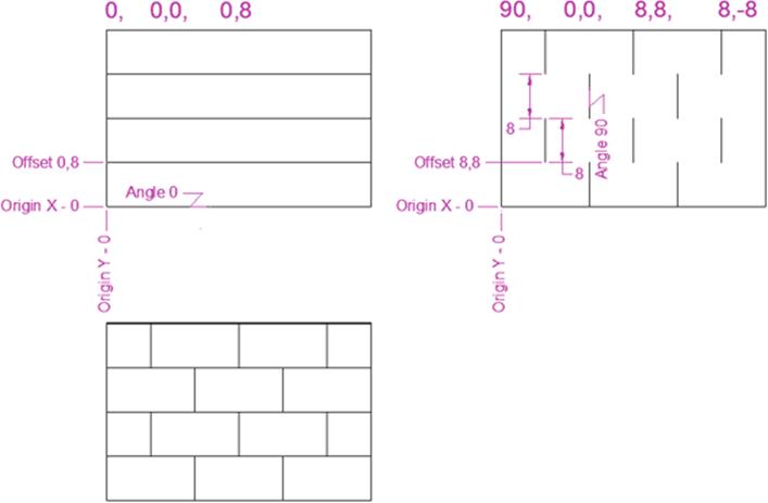
Figure 9.8 shows what each line of the AR-B816 hatch pattern would look if they were separate hatch patterns. You can also see how the offsets, deltas, and dash sequences affect the fi nal results of the hatch pattern.
Figure .
Breakdown of the
AR-B816 hatch
pattern
Defi ning a Custom Hatch Pattern
Hatch-pattern defi nitions are created and stored in PAT fi les using an ASCII text editor such as Notepad (Windows) and TextEdit (Mac OS). As I previously mentioned, I recommend storing
your custom hatch patterns in PAT fi les that you create and not those that came with AutoCAD.
The following explains how to create a new PAT fi le named diamonds.pat on Windows:
1. Do one of the following:
◆ Click Start button ➢ [All] Programs ➢ Accessories ➢ Notepad (Windows XP and Windows 7).
◆ On the Start screen, type note and click Notepad (Windows 8).
2. In Notepad, click File ➢ Save As.
3. In the Save As dialog box, browse to the MyCustomFiles folder you created for the book in the Documents (or My Documents) folder, or to the location in which you want to create the PAT fi le.
4. In the File Name text box, type diamonds.pat.
5. From the Save As Type drop-down list, select All Files (*.*).
6. From the Encoding drop-down list, select ANSI. Click Save.
7. In the editor area, type the following:
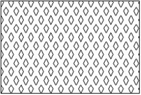
*Diamonds, Diamond sheeting
60, 0,0, 0.8660,1.5, 1.7321,-1.7321
120, 0,0, 0.8660,-1.5, 1.7321,-1.7321
8. Press Enter after the last line in the hatch-pattern defi nition.
9. Click File ➢ Save.
For AutoCAD on Mac OS, you can use these steps to create a new PAT fi le named diamonds.pat:
1. In the Mac OS Finder, click Go ➢ Applications.
2. In the Finder window, double-click TextEdit.
3. On the Mac OS menu bar, click TextEdit ➢ Preferences.
4. In the Preferences dialog box, click the New Document tab.
5. In the Format section, click Plain Text.
6. Close the Preferences dialog box.
7. Click File ➢ Save.
8. In the Save dialog box, type diamonds.pat in the Save As text box.
9. Browse to the MyCustomFiles folder you created for the book in the Documents folder, or to the location in which you want to create the PAT fi le.
10. From the Plain Text Formatting drop-down list, select Unicode (UTF-8).
11. Check the If No Extension Is Provided, Use *.TXT check box, and then click Save.
12. In the editor area, type the following:
*Diamonds, Diamond sheeting
60, 0,0, 0.8660,1.5, 1.7321,-1.7321
120, 0,0, 0.8660,-1.5, 1.7321,-1.7321
13. Press Enter after the last line in the hatch-pattern defi nition.
14. Click File ➢ Save.
Figure 9.9 shows what the Diamonds hatch pattern will look like when used in a drawing.
Figure .
Diamonds hatch
pattern used to fi ll a
rectangle

Using a Custom Hatch Pattern
Custom hatch patterns can be used when creating or modifying a hatch object in a drawing.
Before you can use a custom hatch pattern, AutoCAD must be able to locate the fi le that it is in, unless it was added to acad.pat or acadiso.pat. Once AutoCAD can locate your PAT fi le, you can access the hatch pattern just like you would one of the standard patterns that come with the program.
NOTE If you did not create the custom hatch-pattern fi le in the previous section, you can download the diamonds.pat fi le as part of the sample fi les for this book. The sample fi les can
be downloaded from www.sybex.com/go/autocadcustomization.
Adding Folders with PAT Files to the AutoCAD Support-File Search Paths
The folder that contains your PAT fi les must be added to the AutoCAD support-fi le search paths before they can be used with hatch objects. If you have been following the steps in this book, the fi les should be in the MyCustomFiles folder within the Documents (or My Documents) folder.
Otherwise, just make sure you add the folder where the fi les happen to reside if you placed them elsewhere.
If you are using AutoCAD on Windows, follow these steps:
1. Click the Application button ➢ Options (or at the Command prompt, type options and press Enter).
2. When the Options dialog box opens, click the Files tab.
3. In the Files tree view, click the plus sign (+) next to the Support File Search Path node. If the folder that contains your PAT fi le is listed, click OK and close the Options dialog box.
Otherwise, continue on.
4. Along the right side of the dialog box, click Add and then click Browse.
5. In the Browse For Folder dialog box, browse to the MyCustomFiles folder that you created for this book in the Documents (or My Documents) folder, or browse to the folder that
contains your PAT fi le if you placed it elsewhere.
6. Select the folder that contains the PAT fi le and click OK.
7. Click OK to save the changes to the Options dialog box.
If you are using AutoCAD on Mac OS, use these steps:
1. On the menu bar, click AutoCAD <release> ➢ Preferences (or at the Command prompt, type options and press Enter).
2. When the Application Preferences dialog box opens, click the Application tab.
3. In the Files tree view, click the disclosure triangle next to the Support File Search Path node. If the folder that contains your PAT fi le is listed, click OK and close the Options dialog box. Otherwise, continue on.
![]()
4. Near the bottom of the dialog box, click the plus sign (+).
5. In the Open dialog box, browse to the MyCustomFiles folder that you created for this book in the Documents folder, or browse to the folder that contains your PAT fi le if you placed it elsewhere.
6. Select the folder that contains the PAT fi le and click Open.
7. Click OK to save the changes to the Application Preferences dialog box.
Creating Hatch with a Custom Hatch Pattern
After the folder that contains your PAT fi les has been added to the Support File Search Path node of either the Options dialog box (Windows) or Application Preferences dialog box (Mac OS), you can create a new hatch object using the custom hatch pattern.
NOTE Download the custom hatch pattern.dwg fi le that is part of the sample fi les for this book. The sample fi les can be downloaded from www.sybex.com/go/autocadcustomization.
The following example explains how to create a hatch object using the ribbon in AutoCAD on Windows:
1. Open the custom hatch pattern.dwg fi le.
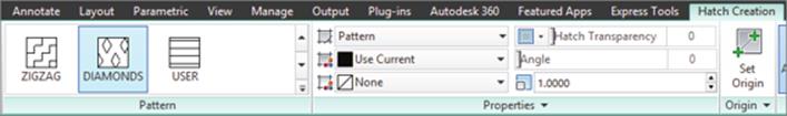
2. On the ribbon, click Home tab ➢ Draw panel ➢ Hatch drop-down menu ➢ Hatch (or at the Command prompt, type hatch and press Enter).
3. Click Hatch Creation tab ➢ Properties panel ➢ Hatch Pattern Style drop-down list ➢ Pattern.
4. Click Hatch Creation tab ➢ Patterns panel ➢ Hatch Pattern gallery ➢ Diamonds (see Figure 9.10). Use the scroll bars along the right side of the Hatch Pattern gallery. Custom hatch patterns are listed near the bottom.
Figure 9.10
Diamonds hatch
pattern in the
Hatch Pattern
gallery
5. Position the crosshairs inside the rectangle and click to create the hatch object.
6. Press Enter to end the hatch command.
NOTE If you are using a release of AutoCAD on Windows that doesn’t support the ribbon or the steps in the example, look up the hatch command in the Help system that came with your release of AutoCAD to learn how to create a hatch object.
Use the following to create a hatch object in AutoCAD on Mac OS:
1. Open the custom hatch pattern.dwg fi le.
2. On the menu bar, click Draw ➢ Hatch (or at the Command prompt, type hatch and press Enter).
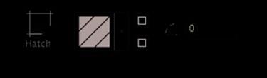
3. On the Hatch visor, click the Pattern button (see Figure 9.11). If you click the drop-down menu button, click Open Library.
Figure 9.11
Pattern button on
the Hatch visor
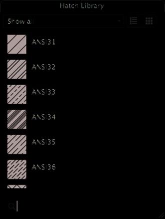
4. When the Hatch Library palette (see Figure 9.12) opens, click the drop-down list and select Custom.
5. Click Diamonds.
6. Position the crosshairs inside the rectangle and click to create the hatch object.
7. Press Enter to end the hatch command.
Figure 9.12
Available hatch
patterns in the
hatch library
NOTE Th e MaxHatch environment variable aff ects the creation of hatch objects that have dense hatch patterns. If the number of lines that are generated for a hatch object exceed the limit specifi ed by the MaxHatch environment variable, a solid hatch is created instead of one made from the hatch pattern. You can use the AutoLISP functions getenv and setenv to work with an environment variable. The value of the MaxHatch environment variable aff ects only the
creation of new hatch objects—and not those already placed in the drawing. The following
example changes the MaxHatch environment variable to a value of 200000:
(setenv "MaxHatch" "200000")
The variable name MaxHatch is case sensitive; you can’t use maxhatch or MAXHATCH; you must
enter it as shown in the s ample code.